

Page 1

Operating manual
D430478XA
vers.
6.0
(1
Page 2

© 2004 SILCA S.p.A - Vittorio Veneto
This manual is written by SILCA S.p.A.
All rights reserved. No part of this publication may be reproduced or used in any form or by any means (photocopying,
microfilm or other) without the written permission of SILCA S.p.A.
Edition:
January 2009
Printed in Vittorio Veneto
by SILCA S.p.A.
via Podgora, 20 (Z.I.)
31029 VITTORIO VENETO (TV) - Italy
IMPORTANT NOTE: in compliance with current regulations relating to industrial property, we hereby state that the
trade-marks or trade names mentioned in our documentation are the exclusive property of authorized
manufacturers of locks and users.
Said trade-marks or trade names are nominated only for the purposes of information so that any lock for which our
keys are made can be rapidly identified.
Page 3

INDEX
REFERENCE GUIDE ...................................................................................................................1
GENERAL ....................................................................................................................................5
1 MACHINE DESCRIPTION ........................................................................................................6
1.1 Main characteristics ............................................................................................................... 6
1.2 Safety ..................................................................................................................................... 7
1.3 Main working parts ................................................................................................................. 8
1.4 Technical data ....................................................................................................................... 9
1.5 Accessories provided ........................................................................................................... 10
2 TRANSPORT ..........................................................................................................................11
2.1 Packing ................................................................................................................................ 11
2.2 Unpacking ............................................................................................................................ 11
2.3 Machine handling ................................................................................................................. 12
3 MACHINE INSTALLATION AND PREPARATION .................................................................13
3.1 Checking for damage ........................................................................................................... 13
3.2 Environmental conditions ..................................................................................................... 13
3.3 Positioning and installation .................................................................................................. 13
3.4 Description of work station ................................................................................................... 13
3.5 Graphics .............................................................................................................................. 14
4 “SET UP” AND USE OF THE MACHINE ...............................................................................15
4.1 Keyboard and functions ....................................................................................................... 15
4.2 Use of the clamp .................................................................................................................. 16
4.3 Cutting by electric contact .................................................................................................... 17
4.4 Cutter ................................................................................................................................... 17
4.5 Changing the cutter ............................................................................................................. 17
5 USER’S GUIDE .......................................................................................................................18
5.1 Symbol and terminology ......................................................................................................18
5.2 Initial Operations .................................................................................................................. 18
5.3 [0] Copy from original........................................................................................................... 20
5.4 Copy from ORIGINAL for FRONT STOP - MALE ................................................................ 24
5.4.1 Reading keys with front stop (double bit, single bit - male) ........................................................24
5.4.2 Cutting keys with front stop (double bit, single bit - male) ..........................................................24
5.5 Copy from ORIGINAL for FRONT STOP - FEMALE ........................................................... 26
5.5.1 Reading keys with front stop (double bit, single bit - female) .....................................................26
5.5.2 Cutting front stop keys (double bit, single bit - female) ..............................................................27
5.6 Copy from ORIGINAL for CENTRE STOP .......................................................................... 28
5.6.1 Reading keys with centre stop (English type) ............................................................................28
5.6.2 Cutting keys with centre stop (English type) ..............................................................................29
5.7 FAS 309 Plastic Stem .......................................................................................................... 30
5.8 Adapter for cutting CHUBB keys with square section stems ............................................... 31
5.9 PUMP KEYS ........................................................................................................................ 32
5.10 MUEL PUMP KEYS .............................................................................................................35
5.11 FIAM KEYS .......................................................................................................................... 38
5.12 KEYS WITH REAR STOP (Male keys and Female keys) ................................................... 43
5.12.1 FRENCH REAR STOP KEYS.................................................................................................... 51
5.13 SMALL BIT / DOUBLE BIT KEYS ....................................................................................... 53
5.14 SPECIAL BIT FEMALE KEYS ............................................................................................. 57
5.15 POST-READING adjustments to make to the key after reading ......................................... 61
5.15.1 Front-rear bit conversion ............................................................................................................62
5.15.2 “X” Specular bit conversion ........................................................................................................ 62
5.15.3 Correcting bit depth ....................................................................................................................63
5.15.4 Bit construction ...........................................................................................................................64
5.16 Decode and copy ................................................................................................................. 66
5.17 Entering the cuts .................................................................................................................. 67
5.18 Use Of The Machine with a Personal Computer ................................................................. 70
5.19 Use of the Machine with OPTIKA via PC.............................................................................. 72
Page 4

5.20 Gauging ............................................................................................................................... 73
5.21 Cutters ................................................................................................................................. 76
5.22 Adapters .............................................................................................................................. 77
6 MAIN MENU TEST FUNCTIONS ............................................................................................85
6.1 Test ...................................................................................................................................... 86
6.1.1 Machine zero points ................................................................................................................... 89
6.2 Options .............................................................................................................................. 106
6.2.1 Serial number ...........................................................................................................................106
6.2.2 Carriage approach speed .........................................................................................................106
6.2.3 Rotating speed .........................................................................................................................106
6.2.4 Preferences ..............................................................................................................................107
6.2.5 Language .................................................................................................................................107
6.2.6 Keyboard inversion ...................................................................................................................107
6.2.7 Limited access to Data (Protected Systems) ...........................................................................108
6.2.7.1 L
6.2.8 Bit height ..................................................................................................................................109
6.2.9 Reading Check .........................................................................................................................109
6.2.10 Machine Messages ..................................................................................................................111
6.2.10.1 ALARM
6.2.10.2 ERROR M
6.2.10.3 SIGNAL M
IST OF ENABLED SYSTEMS
MESSAGES
................................................................................................................. 111
ESSAGES
................................................................................................................ 114
ESSAGES
................................................................................................................ 118
ACTIVATED
AND REMOVAL OF AN ACTIVATION
..............................108
7 MAINTENANCE ....................................................................................................................119
7.1 Trouble shooting ................................................................................................................ 119
7.2 Maintenance operations .................................................................................................... 121
7.3 Cutter replacement ............................................................................................................ 121
7.4 Replacing and tightening the belts ..................................................................................... 122
7.5 Checking and/or replacing fuses ....................................................................................... 123
7.6 Electronic circuit board replacement .................................................................................. 124
7.7 Keyboard/display replacement .......................................................................................... 125
7.8 Access to back compartment ............................................................................................. 126
7.9 Access to bottom compartment ......................................................................................... 126
7.10 Sensor replacement ........................................................................................................... 127
7.11 Replacing the photocell ..................................................................................................... 129
7.11.1 Machine zero setting after replacing the photocells .................................................................131
7.12 Brush replacement ............................................................................................................. 133
7.13 WIN-TRANSFER Program for loading/updating the internal
machine program ............................................................................................................... 133
7.14 DIAGNOSTIC FUNCTION – errors in: Copy from Original on IDEA ................................. 134
8 DISPO6$/ ...................................................................................................136
9 ASSISTANCE ........................................................................................................................137
9.1 How to request service ......................................................................................................137
Appendix 1 - ELECTRIC DIAGRAMS................................................................................... I - VII
Appendix 2 -
DECLARATION COMPLIANCE
Page 5
Operating Manual - English IDEA
*
REFERENCE GUIDE
This manual has been produced to serve as a guide for users of the IDEA key-cutting machine: Read it
carefully; it is essential if you wish to operate your machine safely and efficiently.
CONSULTATION
The contents of the manual are divided into sections relating to:
• Machine description ........................................................................................... Chapter 1
• Transport and installation ................................................................................... Chapters 2-3
• Regulation and use ............................................................................................ Chapters 4-5-6
• Maintenance ....................................................................................................... Chapters 7-8-9
TECHNICAL TERMS
Common technical terms are used in this manual.
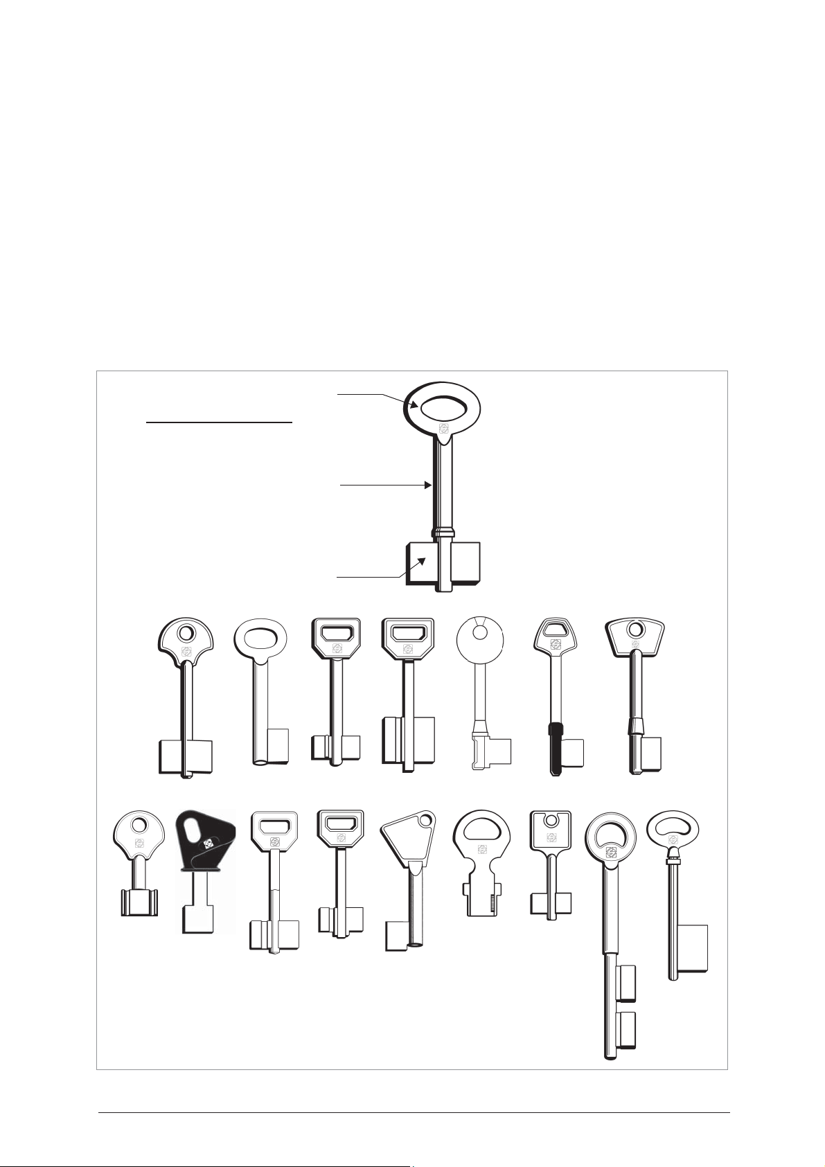
To assist those with little experience of keys and key-cutting, below is an illustration of the terms most
frequently used
WITH OPTIONAL ADAPTERS
*
.
1) Head
2) Stem
3) Bit
head
stem
bit
***
**
Fig. 1
**
Copyright Silca 2004 1
* *
*
*
Page 6
IDEA Operating Manual - English
CHARACTERISTICS OF KEYS FOR READING AND DECODING
The IDEA electronic key-cutting machine is designed to take a number of different types of mortice and bit,
double bit, pump keys, etc. The following are the general key characteristics and conformations for which
the machine has been designed or for which special adapters can be fitted in order to develop specific cutting
systems.
In addition to the machine's general technical characteristics already described, keys with the following
parameters can be cut on the IDEA (fig. 2, fig. 3, fig. 4, fig. 5, fig. 6 and fig. 7).
STEM
- LENGTH: the machine is provided with a headstop and designed to take keys with lengths of up to 150
mm;
- DIAMETER: the self-centering jaws on the rotating clamp will take stems with diameters from Ø 3,6 - 7
mm.
- HOLLOW STEMS: female keys are gripped normally by the jaws and a special tailstock is provided for
self-centering grip on the hole at the tip with diameters from Ø 2 - 5 mm, by centring.
HEAD
- WIDTH: the grip for the head of a bit or double bit key is the means for visual alignment of the key.
BIT
- THICKNESS: maximum 7 mm for brass keys / max. 4 mm for steel keys.
MATERIAL
IDEA is provided with a single phase motor and single cutter speed.
These are the characteristics and variables common to all types of keys. It is now necessary to distinguish
clearly between at least 3 families of keys which condition a series of functions on the machine, such as:
a) tools to use
b) necessary controls.
In the following pages the families of keys are illustrated so that the dimensions of any key to be cut can be
compared and the reference elements found. These elements are:
1) BIT STOP keys(mortice and bit, double bit, round or square stem: mainly for Italian, German, Spanish
markets).
2) SHOULDER STOP keys (with stop on rim close to the bit: mainly for English and Swedish markets).
3) PUMP KEYS (with round and flat stems)
4) SMALL BIT/DOUBLE BIT KEYS
5) SPECIAL BIT FEMALE KEYS
6) KEYS WITH REAR STOP
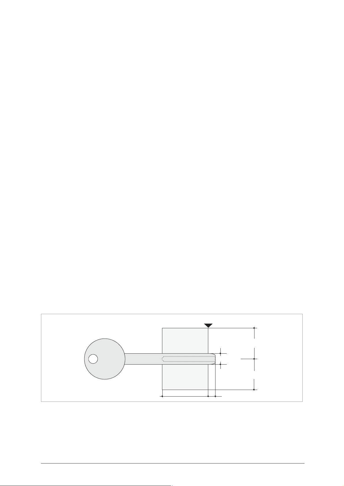
Fig. 2
BIT STOP KEYS (
FIG
. 2)
The minimum and maximum dimensions of this type of key are shown in the diagram below.
This class of key includes:
- mortice and bit and double bit keys
- male and female keys
Stop 0
max.15 mm
max.7 mm
max.15 mm
max.7 mmmax.28 mm
2 Copyright Silca 2004
Page 7
Operating Manual - English IDEA
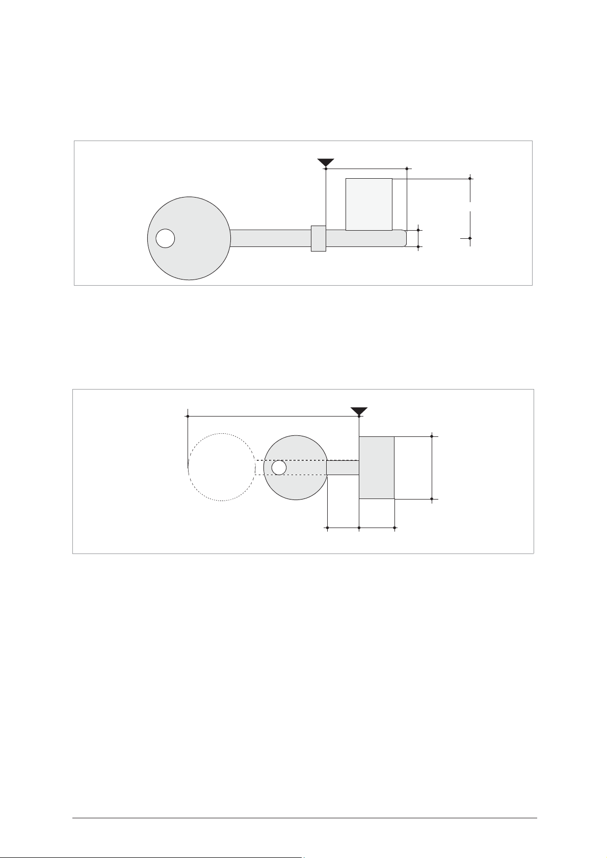
Fig. 3
SHOULDER STOP KEYS (E
NGLISH TYPE
) (
FIG
. 3)
The minimum and maximum dimensions of this type of key are shown in the diagram below.
This class of key includes:
- single bit keys with rim close to the bit
- double bit keys with rim close to the bit
Stop
max.26 mm
max.20 mm
max.6 mm
PUMP KEYS (
FIG
. 4)
The minimum and maximum dimensions of this type of key are shown in the diagram below. To cut this type
of key on the IDEA is necessary the optional adaptor D726180ZB.
This class of keys includes
- pump keys with round stems
- pump keys with flat stems
:
(ø max. 7 mm - min.4 mm)
(7 mm)
Fig. 4
max. 55 mm
min.
12 mm
Stop 3
max. 22 mm
max.
19 mm
Copyright Silca 2004 3
Page 8
IDEA Operating Manual - English
Fig. 5
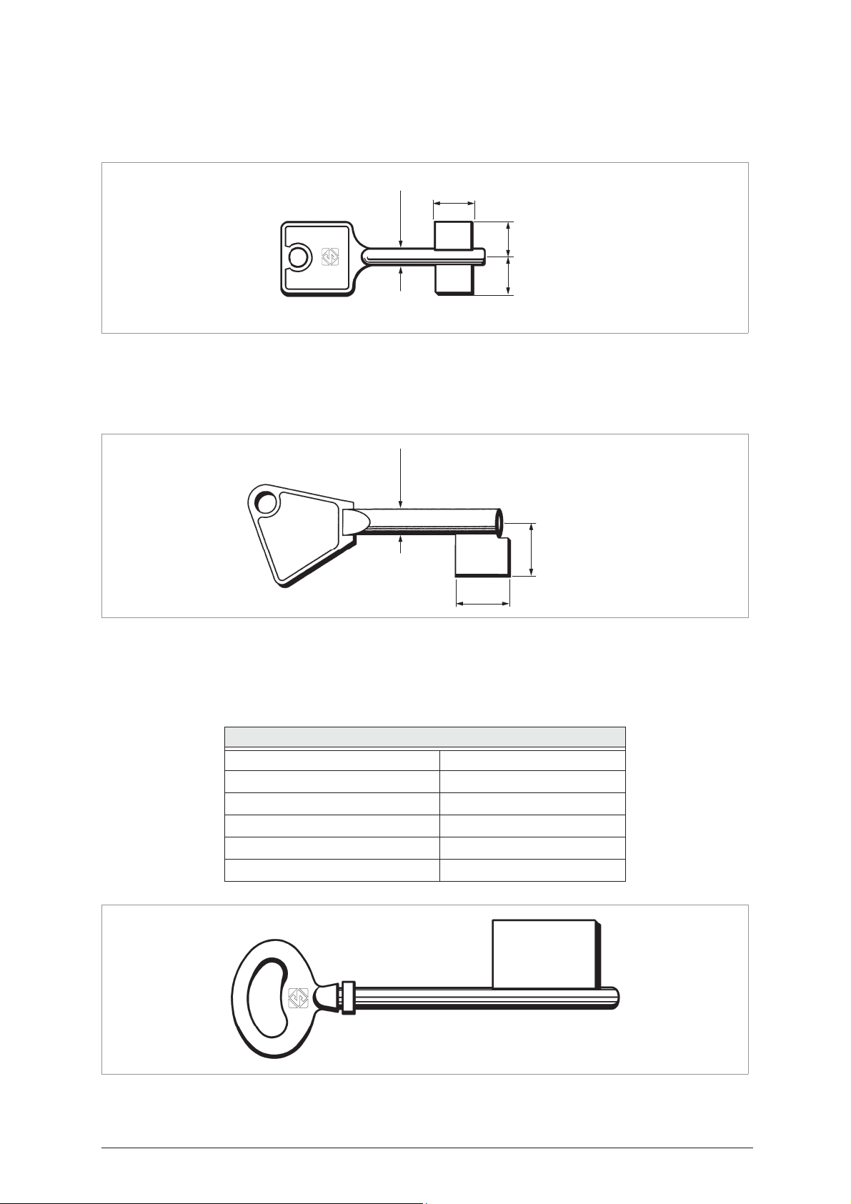
SMALL BIT/DOUBLE BIT KEYS (
FIG
. 5)
The minimum and maximum dimensions of this type of key are shown in the diagram below. To cut this type
of key on the IDEA is necessary the optional adaptor D727711ZB (cap. 5.13 a pag. 53).
max 18 mm
SPECIAL BIT FEMALE KEYS (
FIG
max 4 mm
. 6)
max 12 mm
max 12 mm
The minimum and maximum dimensions of this type of key are shown in the diagram below. To cut this type
of key on the IDEA is necessary the optional adaptor D728717ZB (cap. 5.14 a pag. 57).
max 7 mm
Fig. 6
max 15 mm
max 31 mm
KEYS WITH REAR STOP (
FIG
. 7)
The maximum dimensions of this type of keys are described in the table below. To cut this type of key on the
IDEA is necessary the optional adaptor D727498ZB (cap. 5.12 a pag. 43).
TYPE OF KEYS
Stem diameter min. 5 mm - max. 7 mm
Collar diameter max. 9 mm
Bit length in reading max. 40 mm
Bit height max. 17 mm / 19,5 mm
Distance from stop to bit min. 6 mm
Head width max. 30 mm
Fig. 7
4 Copyright Silca 2004
Page 9

Operating Manual - English IDEA
GENERAL
IDEA has been designed in compliance to the European Community normative (CE).
From the design stage, risks for the operator have been eliminated in all areas: transport, regulation, cutting
and maintenance.
Further risks have been eliminated by means of protective devices.
The materials used to manufacture this machine and all its components are not hazardous.
U
SE
IDEA is designed for cutting keys of ferrous materials: brass, silver nickel, etc.
It must be installed and used according to the instructions indicated by the manufacturer.
If the key-cutting machine is used differently or for purposes different from those described in this manual,
the customer will forego any rights he may have over Silca S.p.A. Furthermore, unforeseen danger to the
operator or any third parties may arise from incorrect use of the machine.
I
NCORRECT USE
Operator negligence resulting in improper use of this machine or failure of the operator to observe the
instructions written in this manual. The manufacturer may decline all guarantees and responsibilities.
It is therefore essential to carefully read this operating manual.
I
MPROPER USE OF ELECTRIC CONTACT
•
it is not permitted
electrical conductivity by means of electric contact.
•
cuts cannot be repeated
I
NSTRUCTIONS MANUAL
The instructions manual provided with the machine is essential to its proper use and to carry out the
necessary maintenance.
We therefore recommend protecting the manual from damage in a safe sheltered place, easily to hand for
quick consultation.
to cut anodized keys, plastic keys or any keys with materials that do not have
on the same side of the key when electric contact cutting is used.
F
URTHER RISKS
No further risks will arise when properly using the IDEA.
P
ROTECTION AND SAFETY PRECAUTIONS FOR THE OPERATOR
IDEA is entirely built in compliance to the Machine Directives. The operations for which it has been designed
are easily carried out with no risk to the operator. The adoption of general safety precautions and observation
of the instructions provided by the manufacturer in this manual eliminate all human error, unless deliberate.
IDEA is designed with features which make it completely safe.
• Power supply
IDEA is supplied with electricity by means of a grounded plug and differential switch.
• Start-up
The machine is turned on by means of a master switch that is located on the Idea’s lower left back side.
• Maintenance
The operations to regulate, service, repair and clean the machine are structured in the simplest and safest
way possible. Parts that the operator can dismount cannot be incorrectly replaced therefore avoiding any
risks.
• Machine identification
The machine is provided with an identification label which includes the machine’s serial number (fig. 8).
Fig. 8
(*) see ch.8 "DISPOS$/", page 136.
Copyright Silca 2004 5
Page 10
IDEA Operating Manual - English
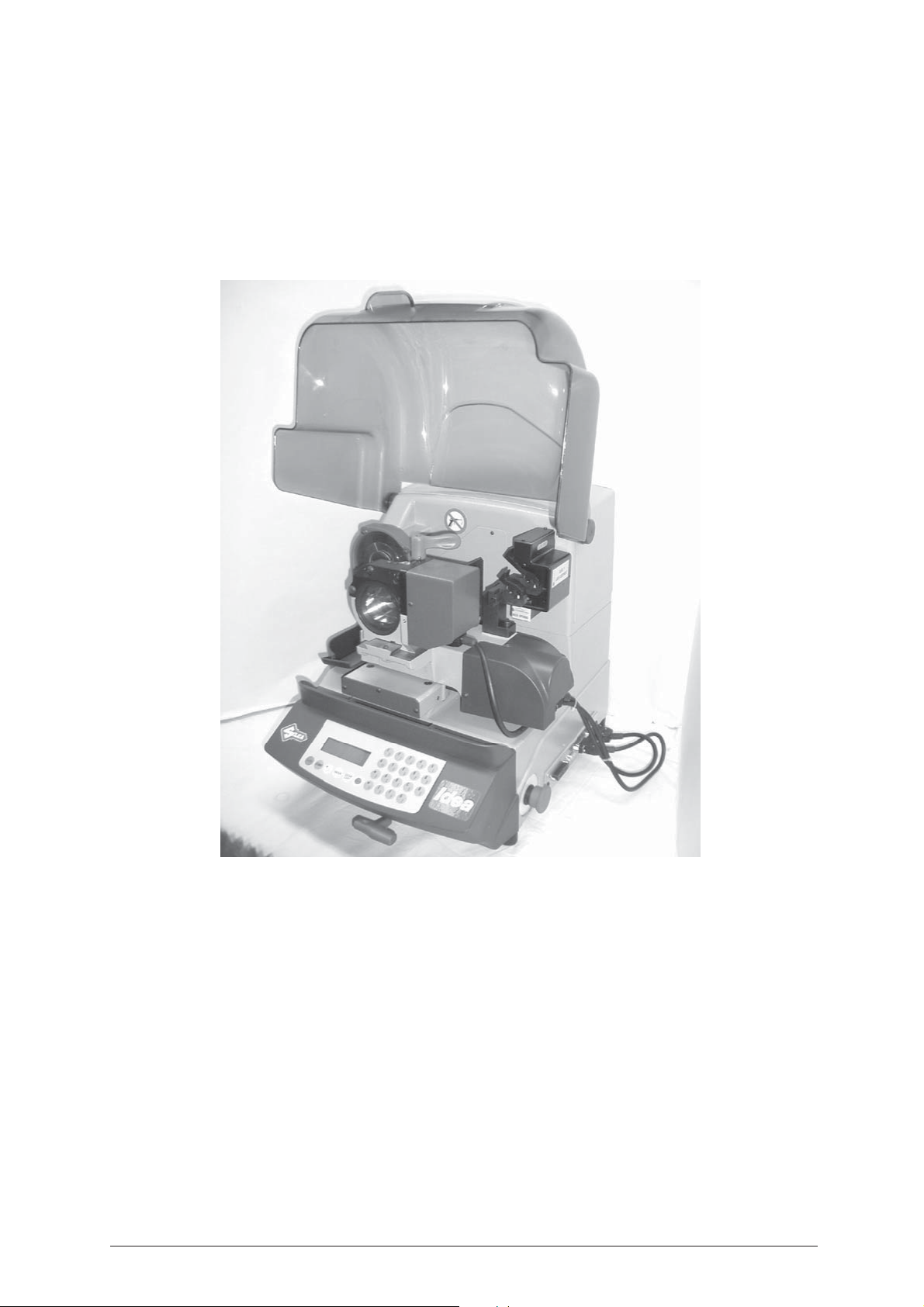
1 MACHINE DESCRIPTION
IDEA is an electronic machine operating on 3 axes (X = spaces, Y = depths, B = radius and bit angles) with
controlled movement. Accurately studied, it adds a high degree of cutting precision to operating speed and
ease of use.
IDEA can be used in 4 different ways:
• entering the key code directly by means of the machine keyboard
• reading the key with a laser reader and reproducing it
• linking to a PC and Silca software
• decode and copy
Fig. 9
1.1
6 Copyright Silca 2004
M
AIN CHARACTERISTICS
• Movements
Movement of the two axes (X-Y) operates on ball screws activated by step motors, on rectified roller guides.
•Clamp
Motorized rotating clamp to control the revolving movement for the cutting radius, to turn over double bit keys
and control the third axis "B";
• Working tool
Consists of a cutter in hard metal carbide (optional High Speed Steel), that is easily replaced.
Suitable to the type of work and speed rotation needed. Optional hard metal carbide cutter.
•Display
Rear-illuminated and placed on the front of the machine.
Display with 4 rows of 20 characters each.
Its technical features and positioning make it highly practical in use.
• Laser reader
Designed to read cuts on keys to be reproduced.
Page 11

Operating Manual - English IDEA
1.2 S
AFETY
• Protective shield
The transparent protective shield is designed to cover the working parts as completely as possible, ensuring
operator safety.
The shield (U) (fig. 10, page 8) must be raised in order to fit keys for cutting or carry out other operations.
Raising of the shield is controlled by a microswitch and disactivates the operating and movement functions,
including the cutter. A special message appears on the display to warn that the shield is not closed.
To re-start the work cycle, place the shield in its original position and press START on the machine’s
keyboard.
• Emergency stops
The red emergency button (N) (fig. 10, page 8) placed on the right-hand side of the machine is used to stop
it immediately in the event of faulty operation or danger for the operator.
When the cause of the emergency has been eliminated, turn the button 45° clockwise to disactivate it.
NOTE: the operator is responsible for keeping the area around the button clear so that it can be
reached as quickly as possible.
• “T” WRENCH HOLDER
The special holder for the “T” wrench (T4), on the front of the machine below keyboard (fig. 10) prevents
damage to the machine caused by inadvertently leaving the wrench on the rotating clamp or the tailstock.
It is therefore essential that the wrench (T4) is placed into its holder after use.
If the wrench (T4) is not in its holder the machine will not begin the cutting cycle and the display will show
the message “T WRENCH INTO HOLDER”.
• Laser warning
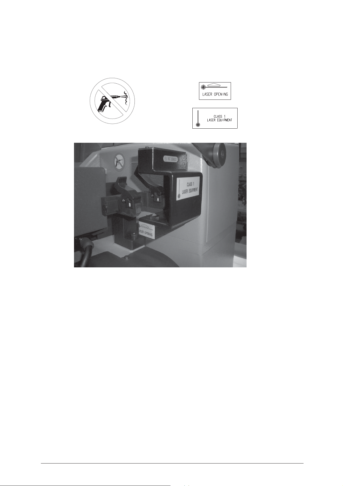
Regulations require that warning labels in the language to be used be attached to the laser reader, as shown
in fig. 15, page 14.
• Cutter motor protection
The cutter motor is protected against overheating by a cut-out switch (located inside the motor) that will
automatically stop the motor if it reaches a certain temperature. Should the switch activate:
1) turn the machine off and disconnect the power supply cable.
2) contact Silca’s Technical Assistance Dept.
Copyright Silca 2004 7
Page 12
IDEA Operating Manual - English
A
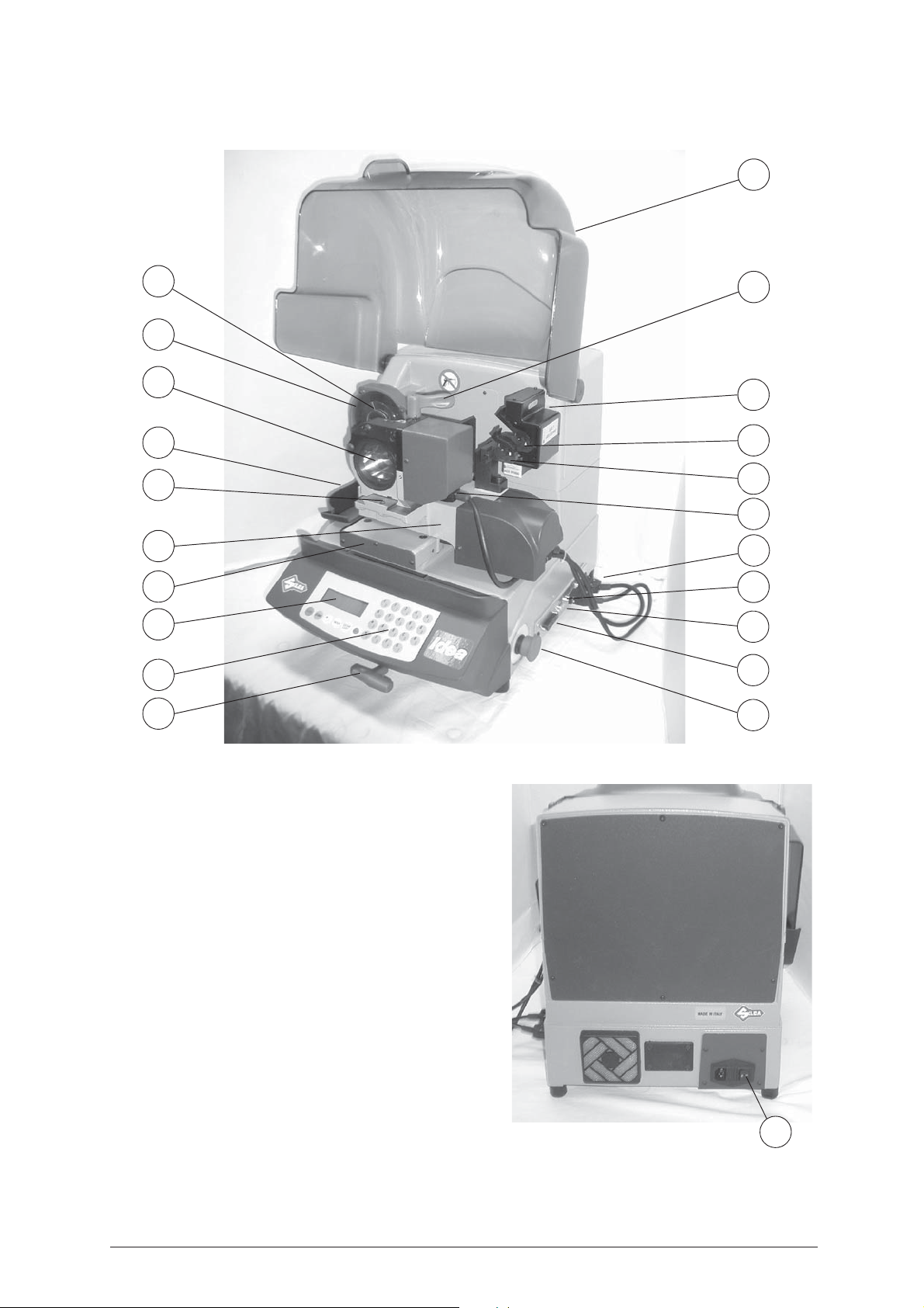
1.3 M
H
I
S1
V
T2
T
AIN WORKING PARTS
U
T1
L
U1
U2
D
R
Fig. 10
S
C
B
T4
O
Q
P
N
A - Master switch
B - Keyboard
C - Display
D - Connector for revolving clamp
H-Cutter
I - Cutter shield
L - Optical reader
N - Emergency button
O - 3rd axis
P - IN/OUT port
Q - Serial port
R - Y axis connector
S - X axis carriage
S1 - Rotating clamp
T - Y axis carriage
T1 - Rotating clamp locking handle
T2 - Rotating clamp removal screw
T4 - ’T’ wrench
U - Protective shield
U1 - Fixed clamp (clamp A)
U2 - Mobile clamp (clamp B)
V - Metal chippings tray
8 Copyright Silca 2004
Fig. 11
Page 13

Operating Manual - English IDEA
1.4 T
ECHNICAL DATA
Electricity supply:
230V-50Hz
Maximum absorbed power:
230V: 2 Amp. 250 Watt
Cutter motor:
single phase and speed
Cutter:
hard metal carbide Ø 100 mm x 1,25 mm
Tool speed:
50Hz: 1150 rpm (+/- 10%)
Movement:
on 2 axes with ball screws activated by step motors, on rectified roller guides.
Possibility to add a 3rd axis to activate the optional tilting and rotating clamps.
Clamp:
revolving
Runs:
X axis: 37 mm Y axis: 32 mm
Dimensions and types of keys:
The machine is designed for cutting keys with the minimum/maximum dimensions described on page 2,
page 3 and page 4.
Dimensions:
width: 500 mm depth: 500 mm height: 420 mm (with raised shield 650 mm)
Mass:
45 kg
Noise level:
sound pressure Lp(A) = 81,5 dB(A) - steel keys / 75,5 dB(A) - brass keys
Copyright Silca 2004 9
Page 14
IDEA Operating Manual - English
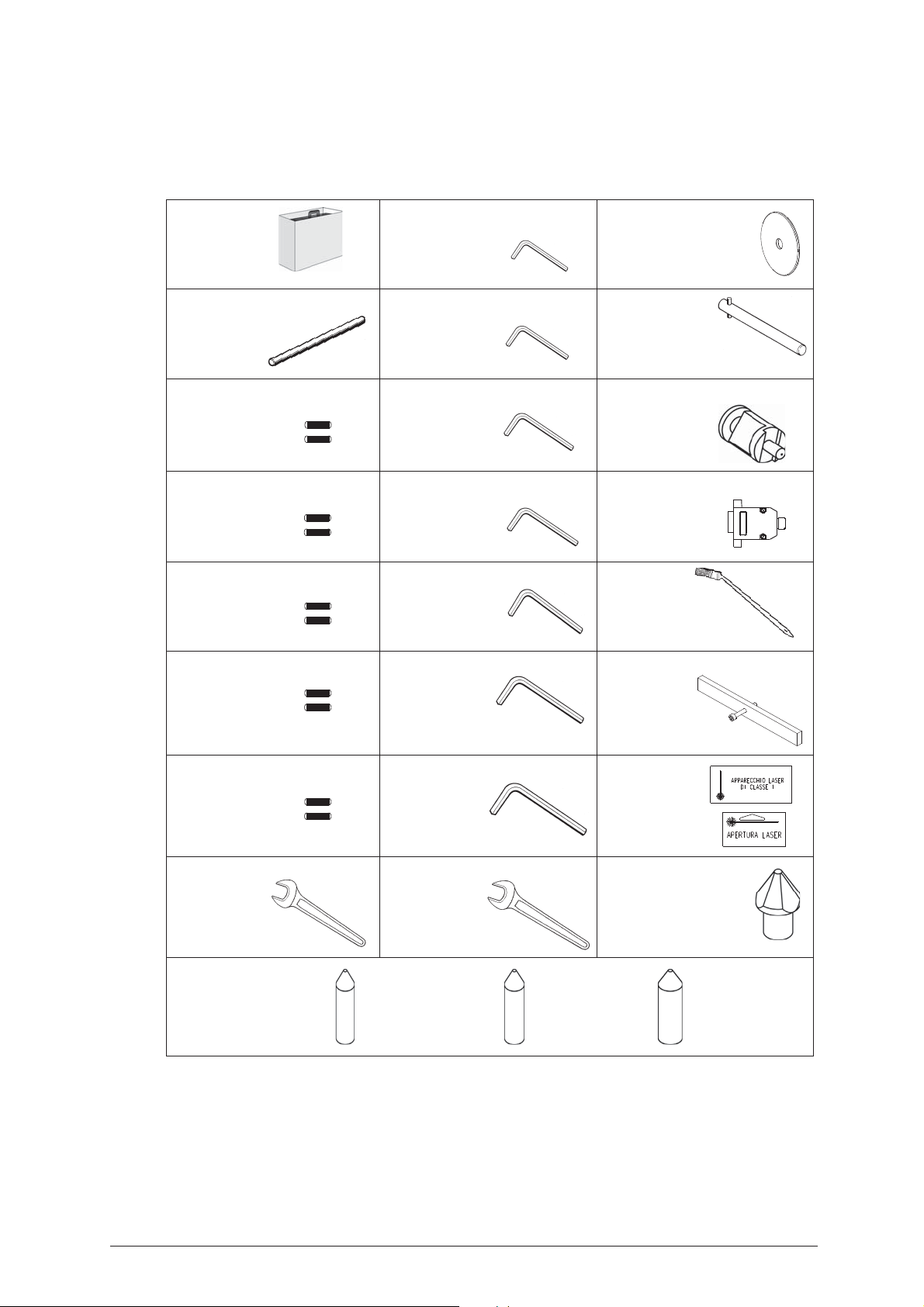
1.5 A
IDEA comes with a set of accessories for its operation and maintenance (tools, hex wrenches, fuses)
supplied in a special tool kit comprising:
tool kit
Cutter release rod
D400754BA
2 Amp fuse - delayed
D312423ZZ
4 Amp fuse - delayed
D308726ZZ
CCESSORIES PROVIDED
1,5 mm allen key
D302434ZZ
2 mm allen key
D300221ZZ
2,5 mm allen key
D300222ZZ
3 mm allen key
D300223ZZ
Z13 template
(regulating disk)
D416657BA
Laser reading
template caliper
(Z14)
Z12 template (regulating block)
D426037BA
Z4 serial test connector
D416661ZZ
6,3 Amp fuse - delayed
D310652ZZ
10 Amp fuse - delayed
D316568ZZ
4 Amp fuse - rapid
D301185ZZ
10 mm spanner
D300308ZZ
centering pin
for female keys:
4 mm allen key
D300224ZZ
5 mm allen key
D300225ZZ
6 mm allen key
D300226ZZ
13 mm spanner
D302788ZZ
Ø 4,5 mm Ø 5,5 mm Ø 6,5 mm
for key stem
4mm : 5mm
for key stem
5mm : 6mm
Slanted
brush
D306935ZZ
Belt tension plate
D416552BA
D202443ZZ
laser
warning
labels
D416816XA
D416817XA
adapter E2
(centering pin for
female keys)
for key stem
6mm : 7mm
10 Copyright Silca 2004
Page 15
Operating Manual - English IDEA
2 TRANSPORT
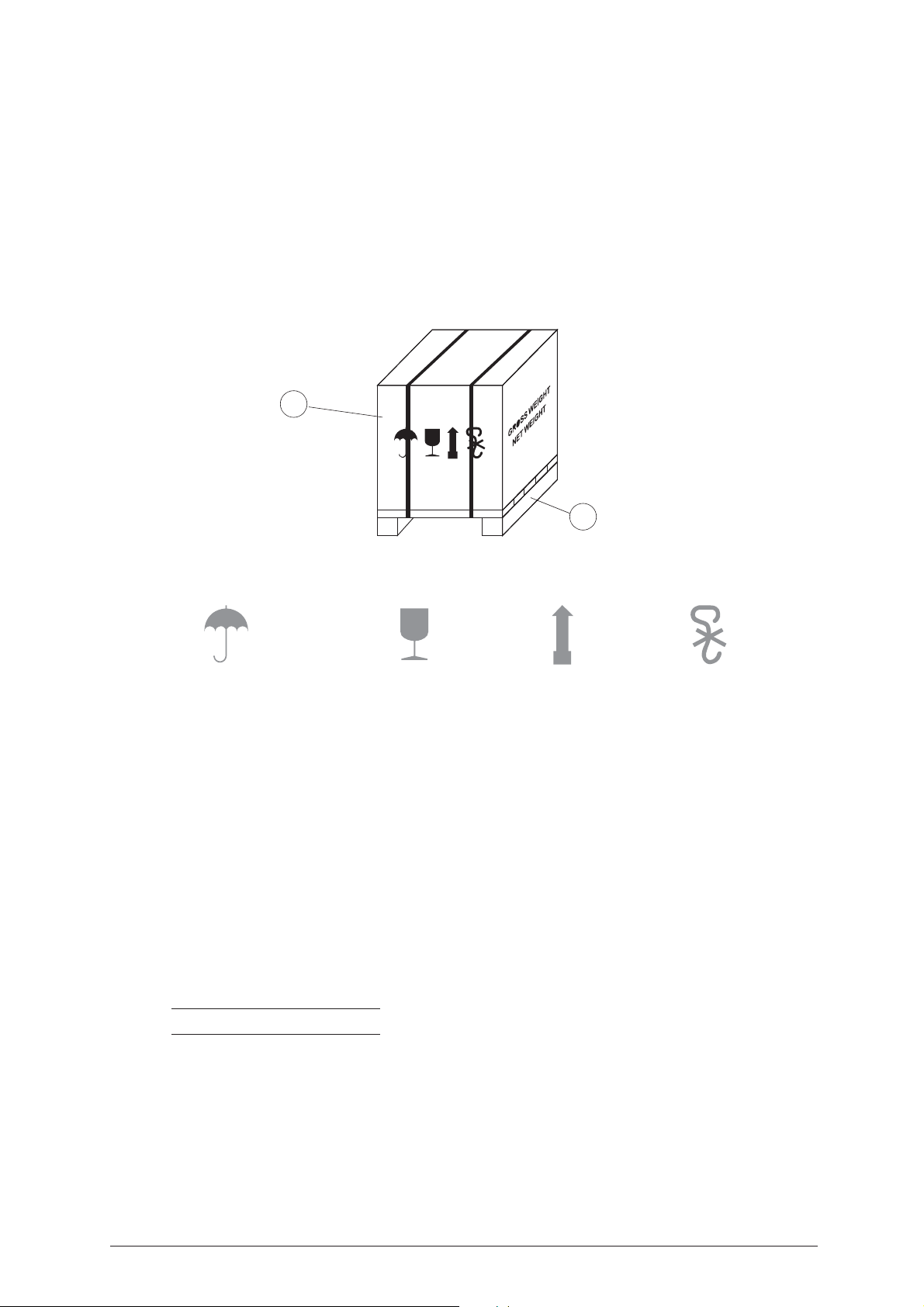
ATTENTION: the key-cutting machine is easily transported and is not dangerous to handle. The packed machine
should be carried by at least two people.
2.1 P
Fig. 12
ACKING
The packing for IDEA is designed to ensure safe transportation and to protect the machine and all its parts.
It comprises a pallet base (b) to which the machine is attached, and a cardboard box as a cover (a).
The machine is fixed to the base of the pallet with screwed down brackets that hold it firm into place. This
prevents the machine and its protective shield from any damage.
The closed packing is held in place by two straps which hold the cardboard box firmly on the pallet.
Symbols are printed on the outside of the cardboard box to give instructions and warnings for transportation.
a
b
To prevent any damage to the machine it is advisable to save and use the brackets provided for future
transportation.
2.2 U
To remove the machine from the packing box:
1) cut the straps with scissors and remove
2) raise the top part of the cardboard box
3) loosen the screws, both on the front and back brackets that hold the machine to the pallet.
4) use the special spanner (provided in the tool kit), to loosen the nuts on the machine’s feet.
5) remove the metal brackets and re-tighten the nuts on the feet.
6) check the contents in the box, that should comprise with the following:
NOTE: we strongly recommend you keep the packing intact for future transportation.
Keep dry
NPACKING
- 1IDEA key-cutting machine
- 1set of documents, including: an operating manual, a spare parts list and a guarantee
- 1power supply cable
- 1tool kit
Handle with care
This side up
Use no hooks
Copyright Silca 2004 11
Page 16
IDEA Operating Manual - English
2.3 M
ACHINE HANDLING
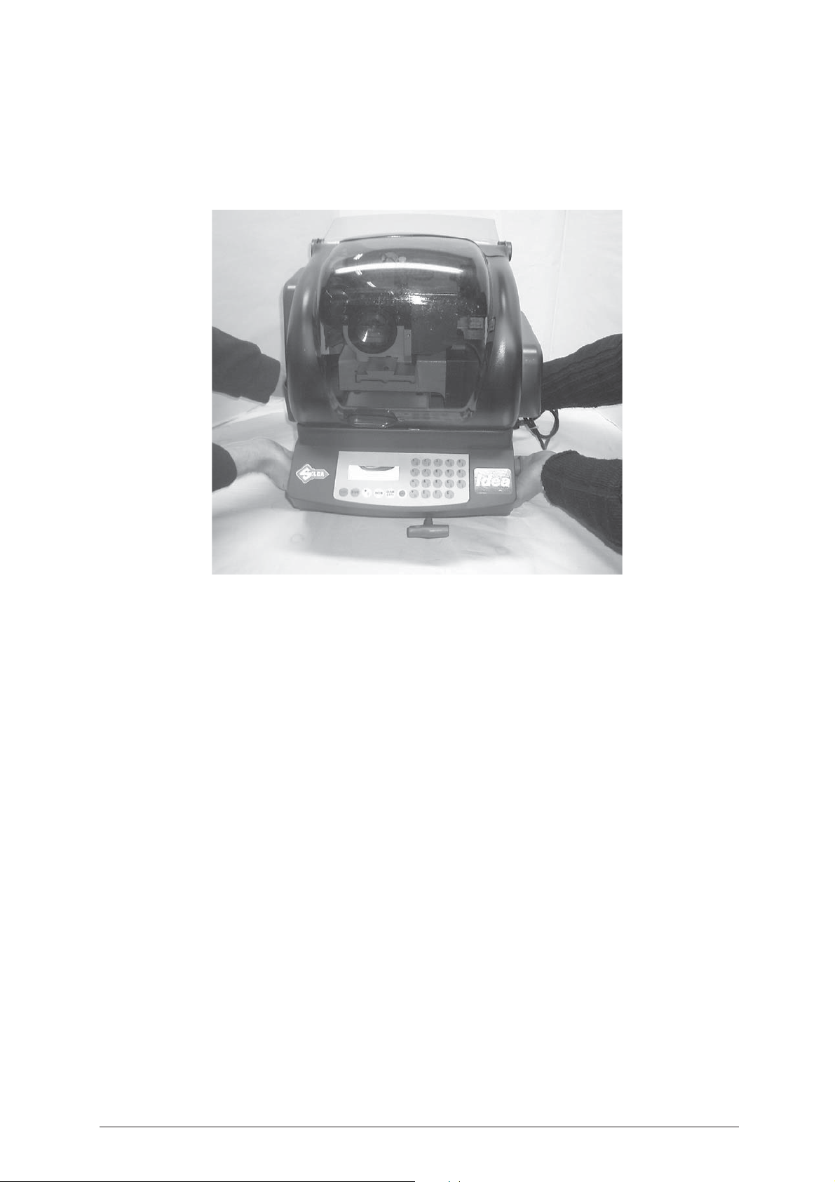
When the IDEA has been unpacked, place it directly on its workbench; this operation should be carried out
by at least two people.
Take care to lift the machine firmly holding the base, and no other part.
ATTENTION: never lift the machine by holding the keyboard stand (fig. 13).
Fig. 13
12 Copyright Silca 2004
Page 17
Operating Manual - English IDEA
3 MACHINE INSTALLATION AND PREPARATION
The key-cutting machine can be installed by the purchaser and does not require any special skills.
It is supplied ready for use and does not need any special set up. However, the operator may have to control
a few things before operating the machine.
3.1 C
IDEA is solid and compact and will not normally damage if transport, unpacking and installation have all been
carried out according to the instructions in this manual. However, it is always advisable to check that the
machine has not suffered any damage.
3.2 E
To ensure that the best use is made of the key-cutting machine, it is important to place it in a well-aired area
which is not too damp.
The ideal conditions for the machine are:
temperature between 10°C and 40°C; relative humidity: approx. 60%.
3.3 P
1) Place the machine on a horizontal surface, solid enough to support the weight of 40 Kg.
2) Ensure that the machines voltage is the same as that of the mains power supply, which must be properly
3) Connect the power supply cable to the power supply socket.
HECKING FOR DAMAGE
NVIRONMENTAL CONDITIONS
OSITIONING AND INSTALLATION
- to work with ease, we suggest that the workbench be approximately the height of the operator’s hip.
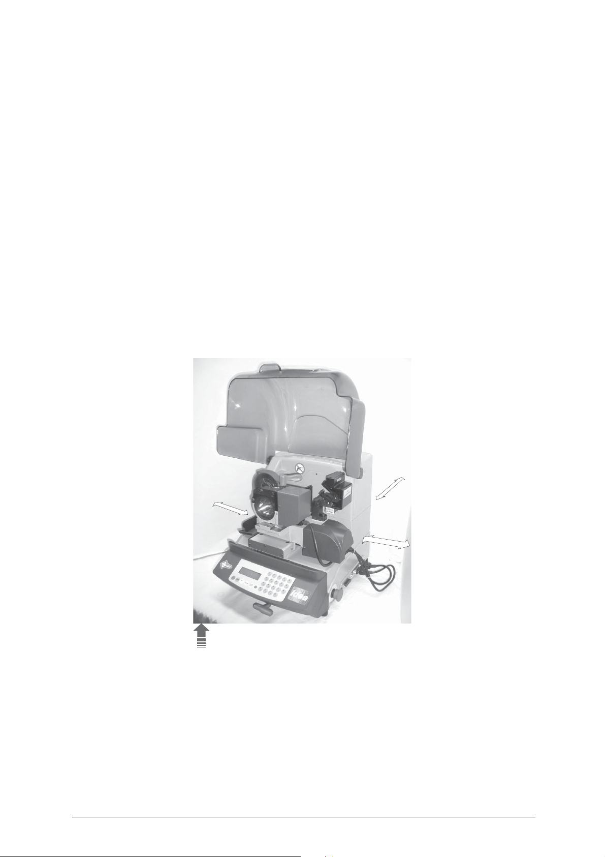
- it is important to leave clearance of at least 30 cm behind the machine and on each side to ensure
proper ventilation.
earthed and provided with a differential switch.
Fig. 14
3.4 D
The machine needs only one operator, who has the following controls at his/her disposal (fig. 10, page 8):
• master switch placed on the back of the machine
• key-positioning clamp
• keyboard
•display
• emergency button
30 cm
30 cm
30 cm
100 cm
ESCRIPTION OF WORK STATION
Copyright Silca 2004 13
Page 18
IDEA Operating Manual - English
Do not use compressed air
for cleaning
Laser warning labels
3.5 G
• The Plexiglass protective shield carries an adhesive warning label (fig. 15). This label must never be
• Two laser warning labels must be attached to the optical reader (fig. 15).
RAPHICS
removed.
Fig. 15
14 Copyright Silca 2004
Page 19
Operating Manual - English IDEA
STOP
START
ENTER
CLEAR
COPY
+
SHIFT
CLEAR
COPY
SHIFT
4 “SET UP” AND USE OF THE MACHINE
4.1 K
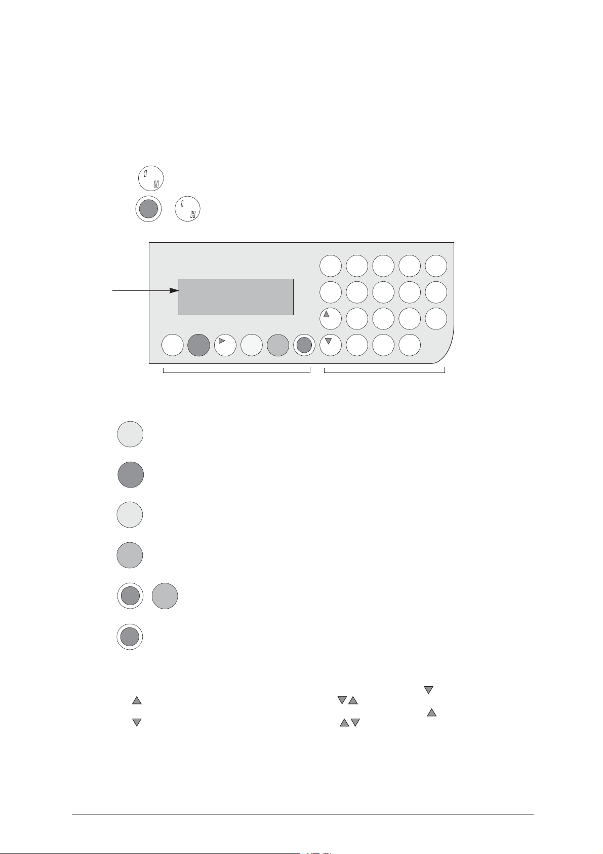
The machine’s keyboard has 19 alphanumeric and 6 function keys.
The alphanumeric keys are used for entering the data card number and the cutting data (numbers and/or
letters) according to the code on the card in use.
Each of the 19 alphanumeric keys contains two characters: the main character (white) which is directly
active, and an alternate character (red), which can be activated by simultaneously pressing the SHIFT key.
E.g.: pressed directly produces:
display
Fig. 16
EYBOARD AND FUNCTIONS
SHIFT
+
STOP
Pressed simultaneously produce:
START
?
function keys alphanumeric keys
ENTER
1
CLEAR
COPY
H
12345
HI JKL
67890
MNOPQ
ABC D
RSTUV
F
SHIFT
E
WX YZ
G
F
UNCTION KEYS
Stop button, particularly when the machine is in motion.
Stops the function in progress at any time in the operation.
Starts the machines operations (only with the shield in its closed position).
Activation of various functions in the menu.
CLEAR: deletes numerical characters.
Combination of SHIFT & CLEAR/COPY enables you to automatically switch to the (0)
“Copy from original” function from any menu in the Idea internal program.
Pressed in combination with all the keys of the same colour to enter the number or letter available.
REGULATING THE DISPLAY
It is possible to modify the angle of vision on the machine’s display by following the instructions below:
• to incline the angle of the display towards the bottom you must press the key and then press the
key, simultaneously keeping them both pressed up until you reach the desired visualization.
• to incline the visualization of the display towards the top you must press the key and then press the
key, simultaneously keeping them both pressed up until you reach the desired angle.
Copyright Silca 2004 15
Page 20
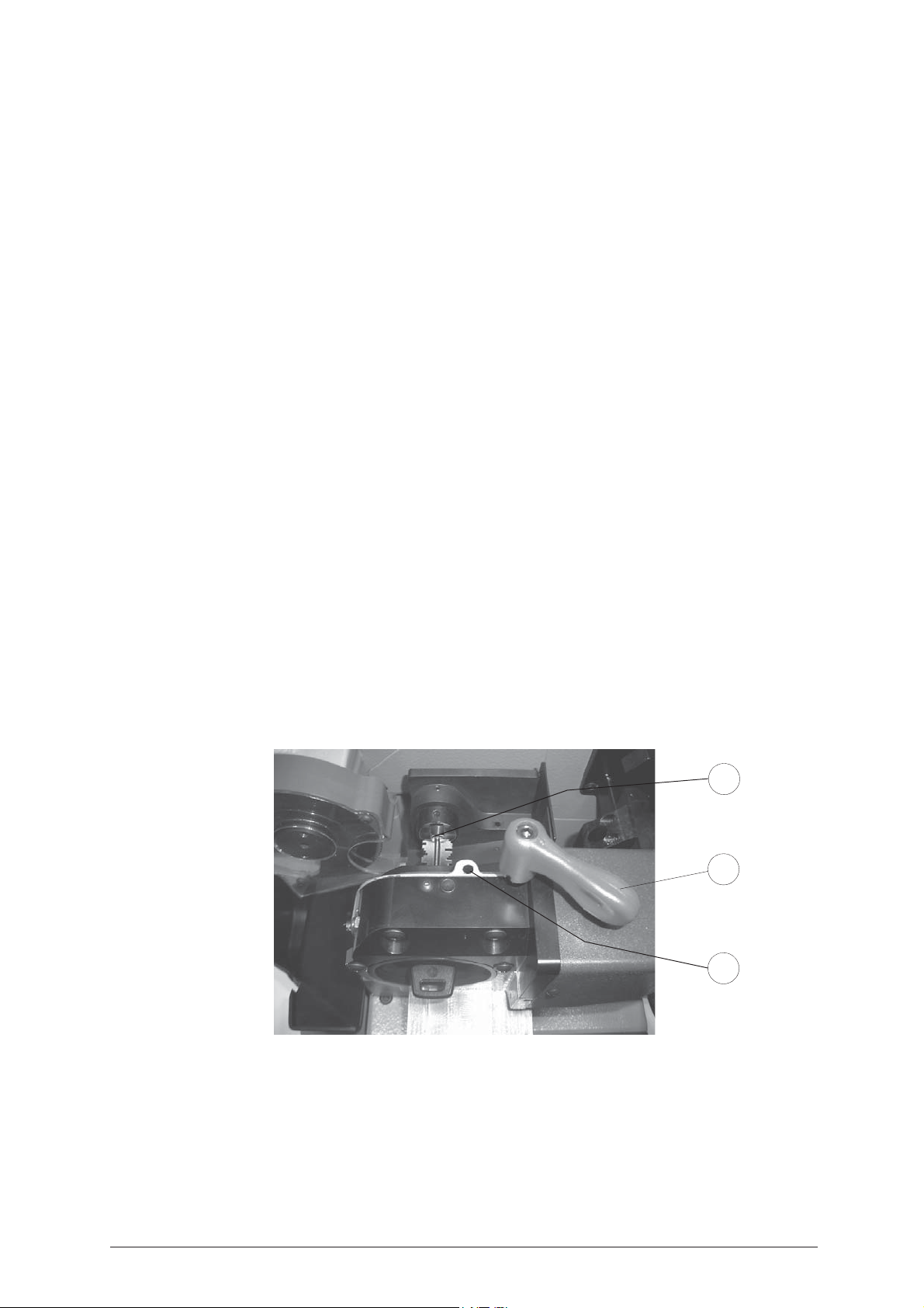
IDEA Operating Manual - English
4.2 USE OF
The rotating clamp (S1) (fig. 17) is the fundamental tool of IDEA. It has various functions and constitutes the
third working axis (rotation) controlled by the machine. The rotating clamp is housed in a mobile support
which runs along the X axis (spaces) and is anchored to the carriage below it by means of a dovetail guide;
this allows the operator to position the clamp at any point along the key stem, ensuring the best grip on the
stem.
L
OCKING
The rotating clamp is locked in position by means of the handle (T1) (fig. 17); the position along the X axis
starts from the resting point for the jaws on the tailstock up to a rear mechanical stop which prevents the
mobile support from coming off dovetail support.
R
EMOVAL
Turn off the machine and pull out the plug. If it is necessary to remove the rotating clamp from the guide (for
cleaning, etc.) turn the knob (T1) to release the underlying mechanical stop. Loosen the screw (T2) (fig. 10,
page 8) and pull out the rotating clamp.
After replacing the rotating clamp into the guide, turn the knob (T1) to activate the stop. Tighten the screw
(T2). Before removing the clamp, remember to disconnect the coupling for the rotating clamp connector
extension (B1) from the “Y axis carriage”, then to connect it again when the clamp has been replaced.
G
RIPPERS
The grippers (G1) are opened and closed by means of the countersunk hexagonal screw (V1), activated by
the “T” wrench (T4) housed on the machine.
The grippers (G1) ensure that the key stem is centred on its axis within the set dimensions (min.3.6 mm,
max.7 mm); the mobile jaws adapt to the diameter of both straight and conical stems. The universal tailstock
support (K1) is designed and set to align the rotating clamp along the axis of the key stem parallel to the
movement of the carriage X (spaces), so that it remains flat under the cutter; this ensures perfect
concentricity between the axis and the key stem with any radial position.
THE CLAMP
F
UNCTIONS
The rotating clamp provides rotation for the keyblank; this serves two main purposes:
1) to provide the cutting radius concentrical to the axis of the key stem during the cutting operation, with a
tolerance of +/- 30°.
2) to turn double bit keys 180°. By means of a PC function, it also provides interpolation of the movements
between the Y axis (depth) and the rotation axis B, enabling “radial cuts with set measurements”.
I
NSERTING THE KEY
The rotating clamp makes it possible to insert keys from either the front or the back, according to the length
of the key.
K1
T1
V1
Fig. 17
16 Copyright Silca 2004
Page 21
Operating Manual - English IDEA
4.3 C
4.4 C
4.5 C
ATTENTION: the thread is left-handed.
UTTING BY ELECTRIC CONTACT
The IDEA key-cutting machine is equipped with a low voltage electrical contact device which permits the
cutter to individualize the key blank as it approaches the cutter during the cutting phase.
Electrical contact is guaranteed for keys in steel, brass, silver nickel, Zamak or iron (with or without nickelplating).
I
MPROPER USE OF ELECTRIC CONTACT
It is not permitted to cut anodized keys, plastic keys or any keys with materials that do not have electrical
conductivity by means of electric contact.
UTTER
The majority of keys utilize the standard cutter for code cutting. Only in certain cases some special keys with
particular type cuts require different cutters.
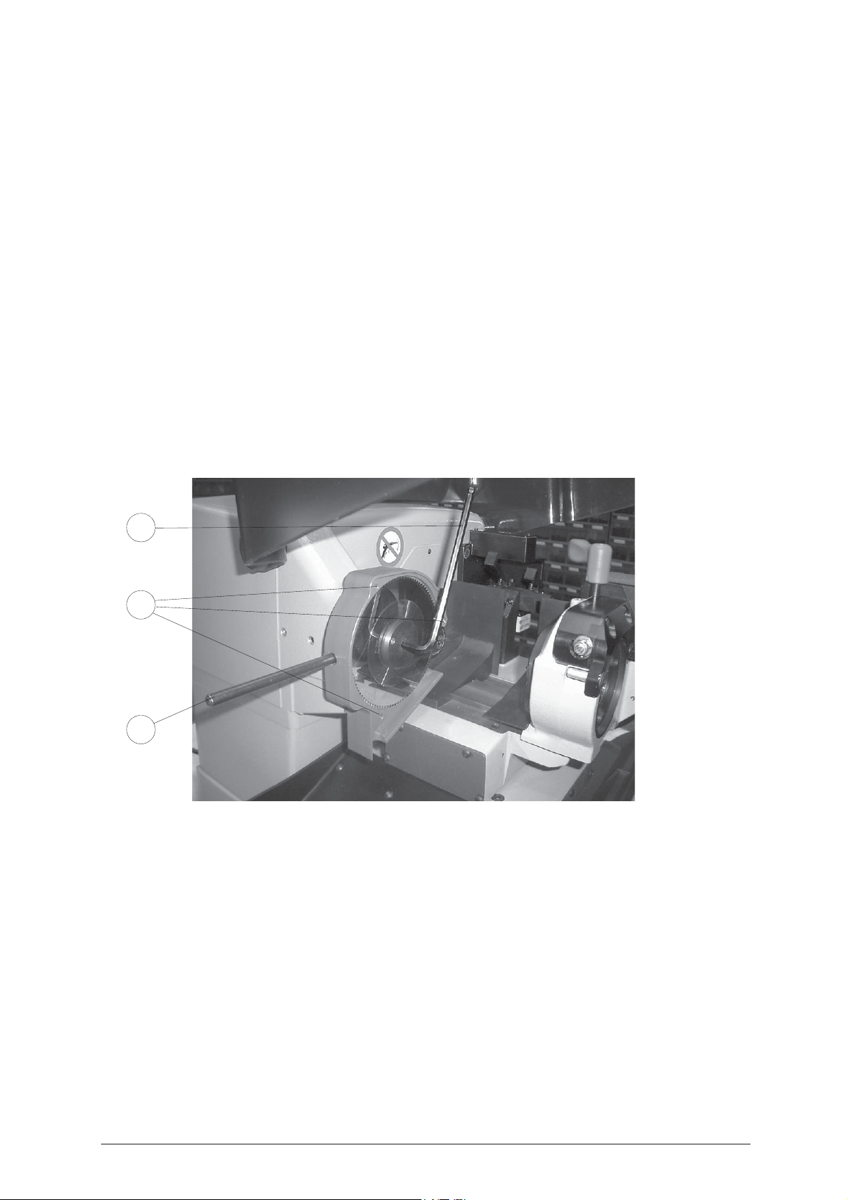
HANGING THE CUTTER
1) raise the protective shield.
2) remove the cutter protective shield by loosening the screw (i2).
3) slide the cutter release rod (X) into the hole located on the left side of the machines cutter shaft chassis
(fig. 18).
4) loosen the cutter locking nut (turning it clockwise) with the allen wrench (X1) provided with the machine.
5) replace the cutter, then tighten the nut (turning it counter-clockwise) and remove the rod from its hole.
6) place the cutters protective shield (i) back into position securing it with the screws (i2).
X1
i2
X
Fig. 18
ATTENTION: when replacing a worn cutter with a new one or with a re-sharpened cutter consult ch. 5.20
"Gauging", page 73.
Copyright Silca 2004 17
Page 22
IDEA Operating Manual - English
5 USER’S GUIDE
I
NTRODUCTION
The Users’ Guide provided below explains how to use the IDEA key-cutting machine without a Personal
Computer.
All the operations are explained step by step so that the machine can be used in the manual mode.
The personal computer programs available that can be connected to the key-cutting machine are used to
transmit data for the cutting and decoding of keys.
Personal computer programs eliminate the need to carry out certain functions manually and skip some of the
screens in the User’s Guide once the data have been transmitted.
When IDEA is used with a Personal Computer, the User’s Guide does not change its viewing logic, except
for the screens that are not required.
5.1 S
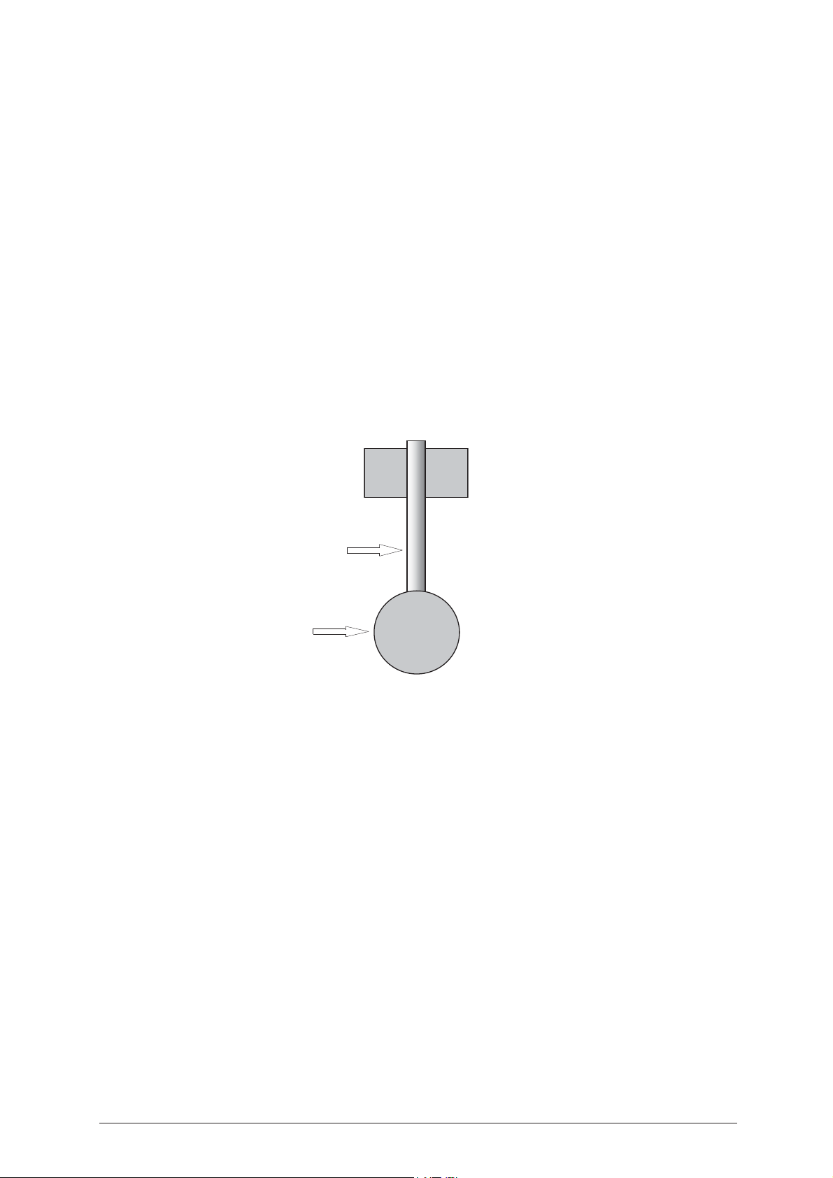
Fig. 19
YMBOL AND TERMINOLOGY
For the sake of clarity, below is a glossary of the commonly used symbols and terms connected with keys or
key-cutting machines.
These symbols and terms will be quoted in the text with a reference to this page, but it will facilitate your
reading if you go through them first.
Cutter: 1.25 (0.492)
B1
= indicates the left-hand bit of the key
B2
= indicates the right-hand bit of the key
indicates the thickness in mm (or inches) of the currently selected cutter
B1 B2
Stem
Head
5.2 I
S1
= initials to identify a key clamp (rotating)
S100
= initials to identify a key clamp (reader)
K1
= initials to identify a tailstock for gripping the key stem from the front
E1
= initials to identify a special adapter used for fitting certain types of keys (fig. 3)
STOP 0
Silca Serial Number (SSN)
key catalogues or Silca software programs.
Make
Brass/Steel
check that the wording corresponds to the material of the key.
After positioning the key-cutting machine on the worktop and connecting the power supply wire to the
machine, proceed as follows:
1) make sure that the emergency push button is off.
2) turn on the machine by means of the switch on the back.
3) to check or edit the working parameters on the machine, go to the "Options [6]" menu (page 106).
: reference for fitting the key into the clamp or tailstock
- Y1 = +00 DEPTH OF BIT 1
- Y2= +00 DEPTH OF BIT 2
= serial number assigned by Silca to each system/lock. They are listed in Silca
= is the make of the lock related to the key to be cut.
= indicates the material of the key to be cut: to use the key-cutting machine properly, always
NITIAL OPERATIONS
18 Copyright Silca 2004
Page 23

Operating Manual - English IDEA
When the machine is turned on, for a few seconds the display shows the internal software version and the
machine model:
IDEA
Version x.x.xxx
Vers DB xx.xx
Version
= this refers to the version of internal software that runs the machine functions. The figure changes
at every upgrade.
Vers DB
= this refers to the version of the data relating to the Systems/Locks entered. You may ask SILCA
to upgrade your machine database with any of the new systems on the market.
The figure changes at every upgrade.
The WinTransfer program (see ch. 7.13, page 133) or the Silca Key Programs can be used to update the
machine program and data by means of a PC and serial port.
The first operation is to set the language for machine messages:
Select language = 2
1: Italiano 2: English
3: Deutsch 4: Français
5: Español
The main menu for the machine program then appears.
O
PERATING KEYS
:
Use the arrow keys [Up/Down] to position the pointer and choose the option by pressing the [ENTER] key,
or enter directly the key relating to the option number.
The symbol >> indicates the other items in the menu that can be accessed with the arrow key [Down].
0 - Copy from original
1 - Decode and Copy
2 - Insert the Cuts
3 - Queue from PC
4 - Calibrations
5 - Maintenance
6 - Options
Copyright Silca 2004 19
Page 24
IDEA Operating Manual - English
5.3 [0] C
ATTENTION: before undergoing laser reading, the original key must always be cleaned to remove any
OPY FROM ORIGINAL
R
EADING PROCESS
The laser reader is used to find the measurements and cuts on original keys so that they can be copied onto
the keyblanks.
accumulated impurities at the base of the negative teeth or frazed parts on the key profile (use the
teflon brush);
- ensure that the positive teeth are not so bent as to obstruct the entry of the beam into the
adjacent spaces;
- with all keys, ensure that the stem is not bent between the tip held by the fixed clamp (A) and the
part of the stem held in the mobile clamp (B);
- position the key so that the transversal axis of the bit/s is as horizontal as possible.
The reading process is started when the program has been selected from the display and the key has been
placed in position on the clamps according to the instructions in the special diagrams for each type of key
(for example: fig. 28, fig. 30, fig. 32, ...).
Excursion during the reading process is limited by the lower jaw of the mobile clamp (B) and the transversal
run is determined both by the type of key and the size of the bit.
The laser reader is programmed to circumscribe the bit/s on the key starting from the contact on the lower
jaw of the mobile clamp (B), to read the diameter of the part of the stem between the mobile clamp (B) and
the bit and to recognise the type of key and its correct positioning according to the selected program. It reads
the first side of the bit following the cuts up to a limit of 0.5 mm from Stop 0 (up against on the fixed clamp
A) then goes on the second side to follow the second bit, or if the key has only one bit, the stem of the key.
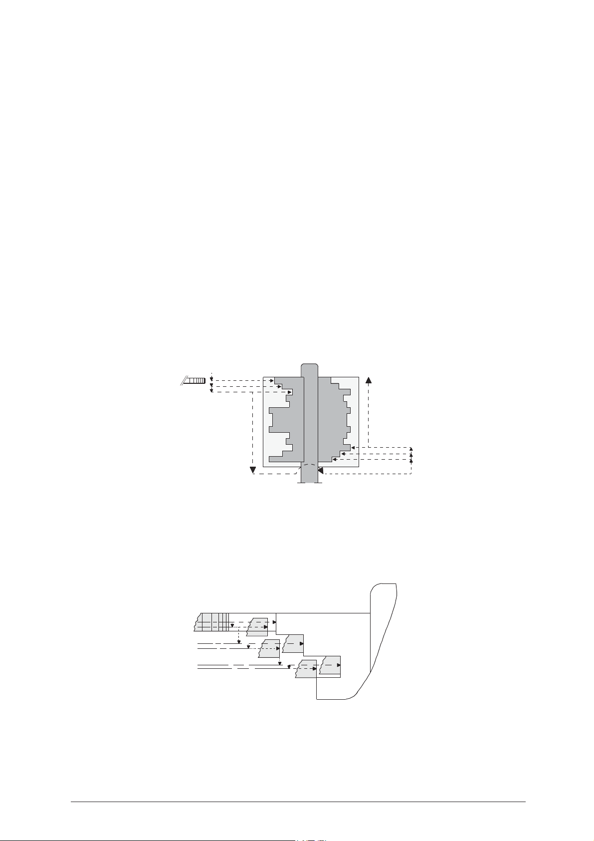
C
UTTING PROCESS
- Cutting begins on the bit on the left-hand side of the stem starting from the tip and going towards the head.
- The second bit, the one on the right, is cut in reverse, i.e. from the head to the tip.
Fig. 20
Fig. 21
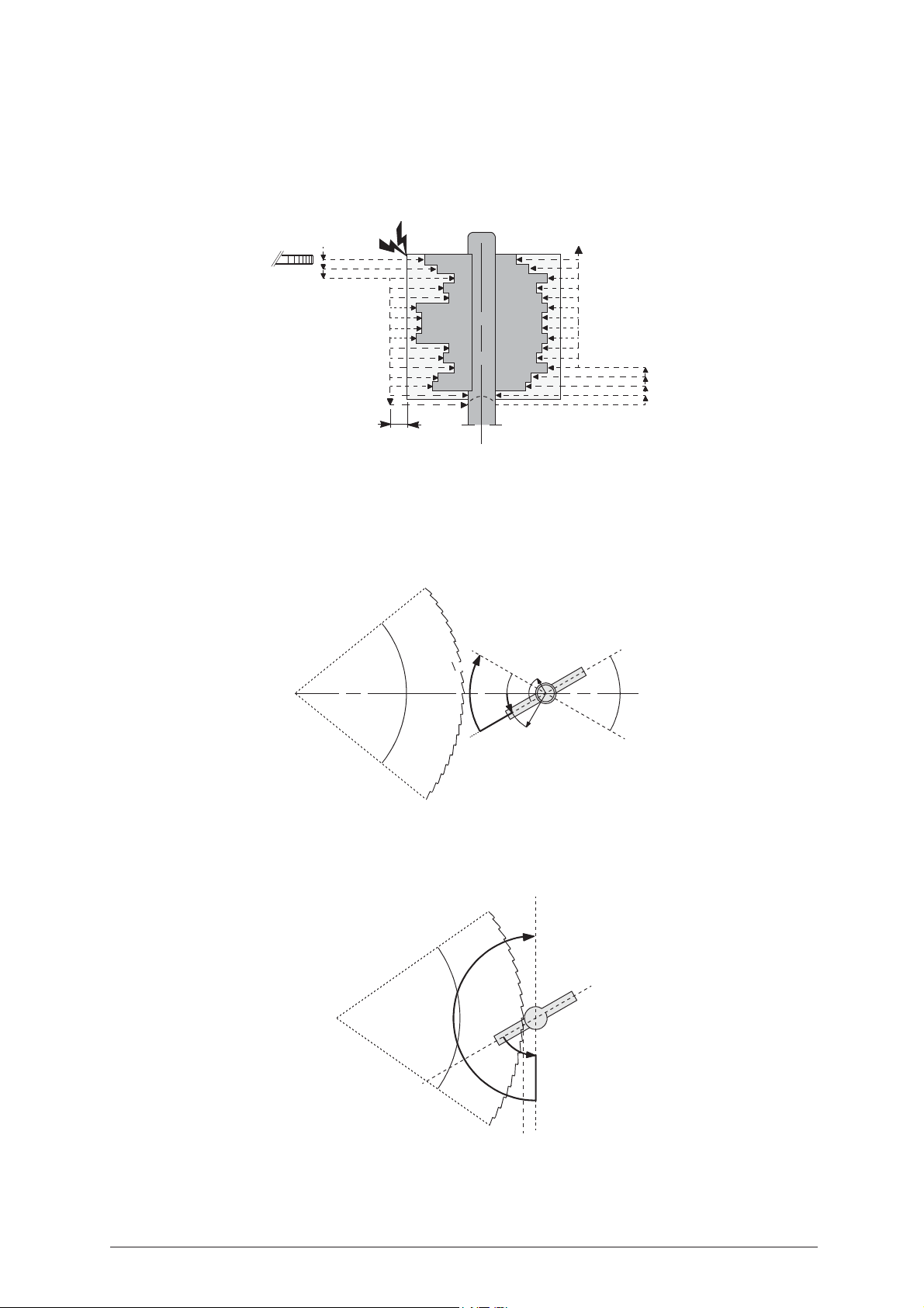
- The cutting path is automatically calculated by the program on the basis of the reading from the original
key. The thicknesses of all the teeth (positive and negative) are compared with the thickness of the cutting
tool stored in the memory (can be read on the machine display by means of the “F2” function). If the
thickness of any of the teeth is less than that of the cutting tool (standard cutting tool, 1.25 mm), the
program will indicate the maximum thickness needed to make an identical copy of the key.
If all the teeth are thicker than the cutting tool, the program will indicate the difference and the number of
times the cutting tool needs to pass to reproduce the cuts correctly.
20 Copyright Silca 2004
Page 25
Operating Manual - English IDEA
- The cutting tool is brought into contact with the bit at reduced speed to determine the size, then the tool
withdraws to the safety distance before beginning the next cut.
- The purpose of the entire procedure is to reduce the backwards and forwards movement of the cutting
tool, limiting its excursion to within a new safety measurement of 2 mm beyond the edge of the bit, thereby
accelerating the cutting process.
2 mm
Fig. 22
C
UTTING
- On taking the key up to the cutting tool, the rotating clamp imposes an anticlockwise angle of -30° to the
transversal axis of the bit, thus facilitating cutting by providing a single direction (+60° clockwise) for the
cutting radius after the depth for the tooth being cut has been reached.
Fig. 23
+60°
-30°
R1
30°
30°
R2
- At the end of the cutting operation on the left-hand bit, the cutting tool trims the bit up to the stem (diameter
read from the original key) thereby rectifying the diameter of the stem as the key turns simultaneously,
together with the removal of any portion of bit which exceeds the length of the original.
+180°
-60°
Fig. 24
Copyright Silca 2004 21
Page 26
IDEA Operating Manual - English
Ø min.Ø max.
max.
min.
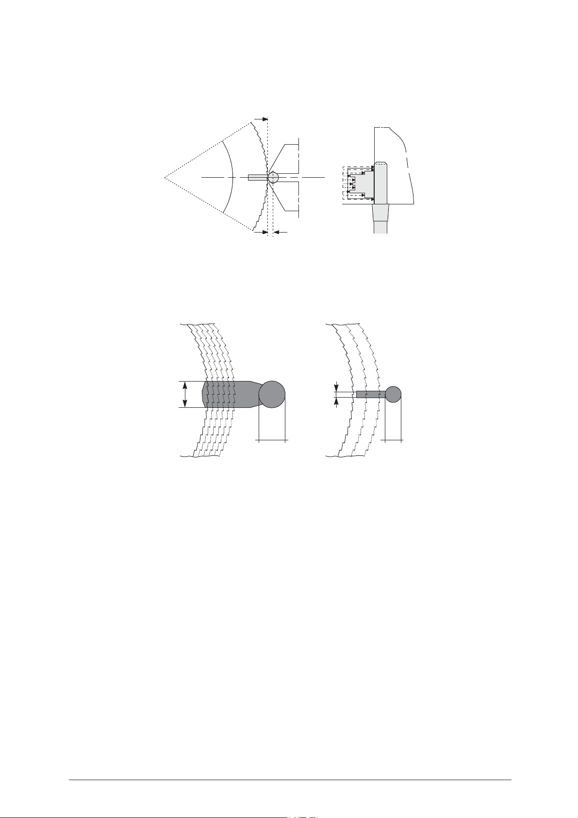
- With square stemmed keys the program applies a special bit trimming process which does not remove the
edges of the stem. The key is positioned on the horizontal axis at a distance of 2 mm from the end of the
stem; the cutting tool then enters tangentially on the vertical side of the stem so that any portion of the bit
which exceeds the original measurement can be removed.
Stop 1
min. 2 mm
Fig. 25
- The speed ratio is selected from a scale of diameters sub-divided proportionally between a minimum
diameter of 3.6 mm and a maximum diameter of 7 mm; in effect, the thicker the key, the slower the
advancing speed of the cutting tool.
- The advancing speed of the tool over the bit (not to be confused with the speed of cutting, or tool operation,
which depends on whether the material is brass or steel) is automatically adopted by the program
according to the diameter of the stem read from the original key.
Fig. 26
It is now very important to distinguish the type of key to be copied.
22 Copyright Silca 2004
Page 27
Operating Manual - English IDEA
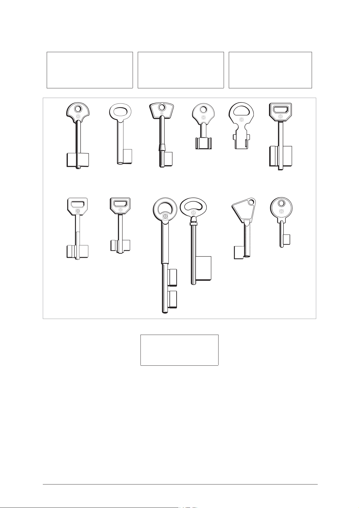
SELECT TYPE OF KEY
3 - Pump 7 - Rear stop
0 - Bit stop male 4 - Square-square tip 8 - Rear stop french
1 - Bit stop female 5 - Square-round tip 9 - Small bit
2 - Shoulder stop 6 - Square stepped tip 10 - Special bit female
Bit stop
MALE
Bit stop
FEMALE
SHOULDER
stop
PUMP
keys
MUEL PUMP
keys
SQUARE
tip
SQUARE-ROUND
Fig. 27
tip
SQUARE
STEPPED tip
Special
BIT FEMALE
Small
BIT
REAR
STOP
Select the operation to be carried out on the selected key:
1 - Reading + Copying
2 - Cutting only
3 - Reading only
4 - Post-Reading adj.
1) Reading + Cutting: the key and cutting data are read
without interruption
.
2) Cutting only: the previously read key is cut.
3) Reading only: the key is read;
in this way the cuts read can be edited before cutting the key
.
4) Editing of key read: the original key read can be edited in order to adjust any defects or broken parts (see
ch. 5.15, page 61).
Copyright Silca 2004 23
Page 28
IDEA Operating Manual - English
5.4 C
OPY FROM
Clamp: S100 A-B =
Stop 0 =
ORIGINAL
reference or positioning point on the key reading clamp.
FOR
FRONT STOP - MALE
Original on right
Clamp: S100 A-B Stop: 0
[START]
indicates the clamp (
KEY READING
S100
) into which the key must be fitted, and which jaw to use.
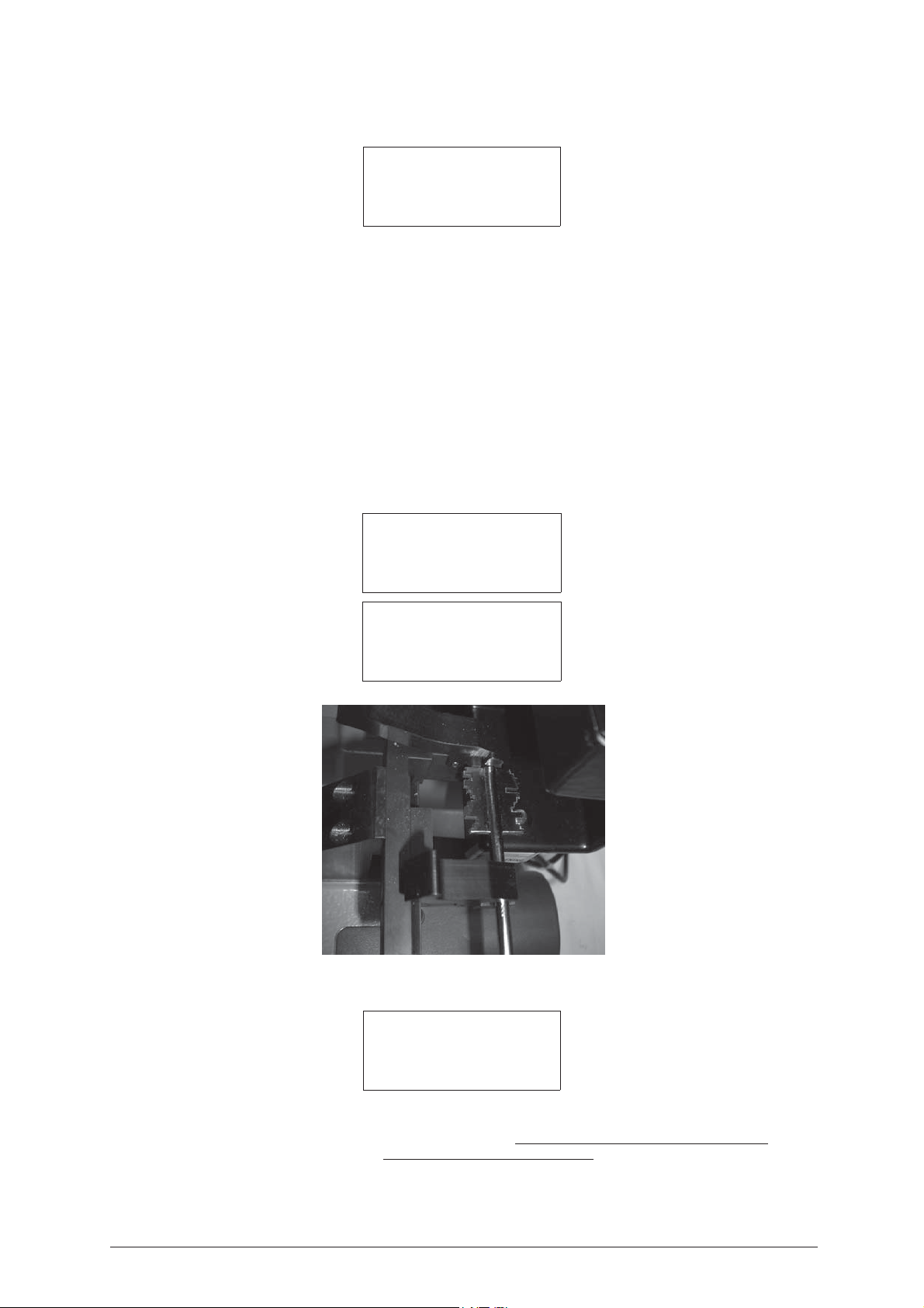
5.4.1 Reading keys with front stop (double bit, single bit - male)
1) open the fixed clamp (A) and the mobile clamp (B) by exerting pressure on the jaw lever.
2) fit the key into the special V-shaped groove (axis X1) taking the bit all the way into the fixed clamp (A).
ATTENTION: position the key so that the highest tooth is facing left, ensuring contact with the stop (0) on the
vertical side of the tooth.
3) release the jaw lever.
4) place the mobile clamp (B) in the ideal position for the stem between the bit and head making sure that
between the bit and internal side of the mobile clamp (B) there is a distance of min. 3 mm and max. 10 mm.
5) when the reading process is started, the carriage takes the key into contact with the laser beam along the
path and in the direction indicated by the broken line.
6) at the end of the cycle see the message on the display in order to continue (see ch.5.4.2).
Reading in progress…
Data processing
in progress
Please wait…
Fig. 28
5.4.2 Cutting keys with front stop (double bit, single bit - male)
Left blank Brass
Clamp: S1-K1 Stop:0
Cutt.: 1.25
Pcs. = 1/1 [START]
Clamp: S1- K1 =
Stop 0 =
Cutter: 1.25 =
Brass/Steel =
reference or positioning point on the key cutting clamp.
indicates which clamp (S1) and tailstock (K1) to use for gripping the key.
thickness of the cutter currently selected (press SHIFT+ENTER to change thickness)
material of the key (press SHIFT+ ? to change material)
24 Copyright Silca 2004
Page 29
Operating Manual - English IDEA
ATTENTION: always check that the wording corresponds to the material of the key.
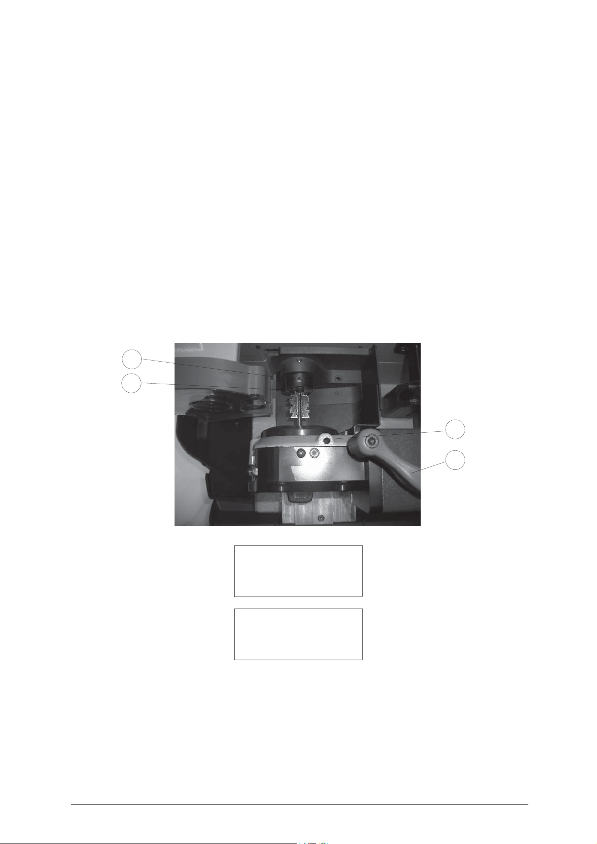
The key blank to be cut must be positioned according to the parameters given on the display after selecting
the program involved; the type of key with front stop requires the use of the rotating clamp (S1), the ‘K1’
tailstock support and the key reference on “Stop 0”.
Please follow the instructions below carefully, and observe the order of operations.
1) Loosen the knob (T1) by turning it anticlockwise until the rotating clamp (S1) can be moved to a convenient
distance for fitting the key.
2) Orient the standard tailstock (K1) for male keys in the special seat on the support, using the screw (V2) to
direct it upwards (fig. 29).
3) Take the T wrench (T4) from its seat and open the rotating clamp jaws by turning the sunk hex. screw
(V1); at the end of the operation leave the T wrench in the screw (V1).
4) Fit the key blank into the rotating clamp (S1) from the front, placing the stem in position on the jaw groove,
then place the key tip into the tailstock (K1).
5) Close the mobile clamp jaws slightly, using the T wrench already in the screw (V1), without gripping the
key stem; move the rotating clamp (G) towards the tailstock, keeping a minimum safety distance of 10 mm
between the rotating clamp jaws and the rear limit of the bit. Secure the rotating clamp in position by
means of knob (T1).
6) Hold the key head in the left hand and align crosswise, making sure that the bits are all the way up against
the grips on the tailstock (K1), at the same time close the grips round the key stem, using the T wrench
(T4) already in place on the screw (V1).
7) Transfer the T wrench (T4) onto the screw (V2) of the tailstock and secure the tip of the key.
8) Replace the T wrench in its seat, lower the mobile safety shield and begin the process with START.
To remove the key after cutting, carry out the operations described, in reverse order.
Fig. 29
V2
K1
V1
T1
Cutting in progress
Copy: 1 of: 1
Copy: 1 of: 1
finished
More copies ?
No=STOP Yes =ENTER
You can now press ENTER in order to make further copies of the previously read original key.
Copyright Silca 2004 25
Page 30
IDEA Operating Manual - English
5.5 C
OPY FROM
Clamp: S100 A-B =
Stop 0 =
ORIGINAL
reference or point for positioning the key on the reading clamp.
FOR
FRONT STOP - FEMALE
Original on right
Clamp: S100 A-B Stop: 0
[START]
indicates the clamp (
KEY READING
S100
) into which the key must be fitted, and which jaw to use.
5.5.1 Reading keys with front stop (double bit, single bit - female)
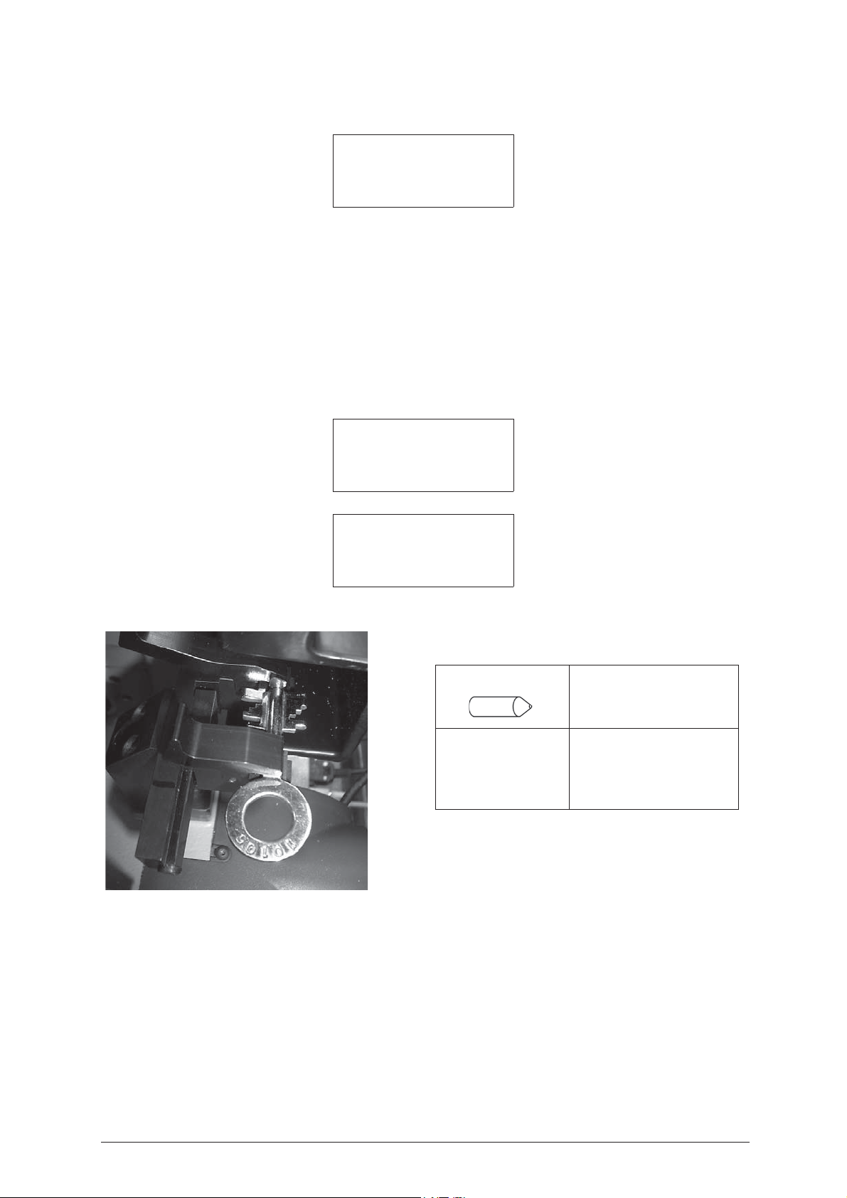
1) Press on the grip lever of the fixed clamp (A) and fit the centring device (see table) so that it protrudes
towards the mobile clamp (B). Release the grip lever.
2) Press on the grip lever on the mobile clamp (B) and fit the key so that the hole in the stem is up against
the centring device. Release the grip lever.
3) Hold the key head with one hand and the end of the centring device with the other and push the key up
against the stop 0 (A).
4) The ideal position for the mobile clamp (B) is when there is a distance of 3 mm min. and 15 mm max.
between the bit and inner side of the mobile clamp (B) (see ch.5.5.2).
Reading in progress…
Data processing
in progress
Please wait…
Press START to proceed with cutting the key (see ch.5.5.2).
CENTRING Ø STEM
Ø 4,5 mm from Ø 4 mm to Ø 5 mm
Ø 5,5 mm from Ø 5 mm to Ø 6 mm
Ø 6,5 mm from Ø 6 mm to Ø 7 mm
Fig. 30
ATTENTION: make sure that the bit is up against the stop 0 (A).
ATTENTION: position the key so that the highest tooth is facing left, ensuring contact with the stop (0) on the
vertical side of the tooth.
5) start the reading process, which will take the reader along the path indicated by the broken line. At the end
of the cycle see the message on the display in order to continue.
26 Copyright Silca 2004
Page 31
Operating Manual - English IDEA
5.5.2 Cutting front stop keys (double bit, single bit - female)
Left blank Brass
Clamp: S1-K1 Stop:0
Cutt.: 1.25 Adap.: E2
Pcs. = 1/1 [START]
Clamp: S1- K1 =
Stop 0 =
reference or point for positioning the key on the cutting clamp.
Cutter: 1.25 =
Brass/Steel =
Adapt: E2 =
indicates which clamp (S1) and tailstock (K1) to use for gripping the key.
thickness of the currently selected cutter (press SHIFT+ENTER to change thickness).
material of the key (press SHIFT+ ? to change material).
adapter for positioning the key (female) from the tip.
ATTENTION: always check that the wording corresponds to the material of the key.
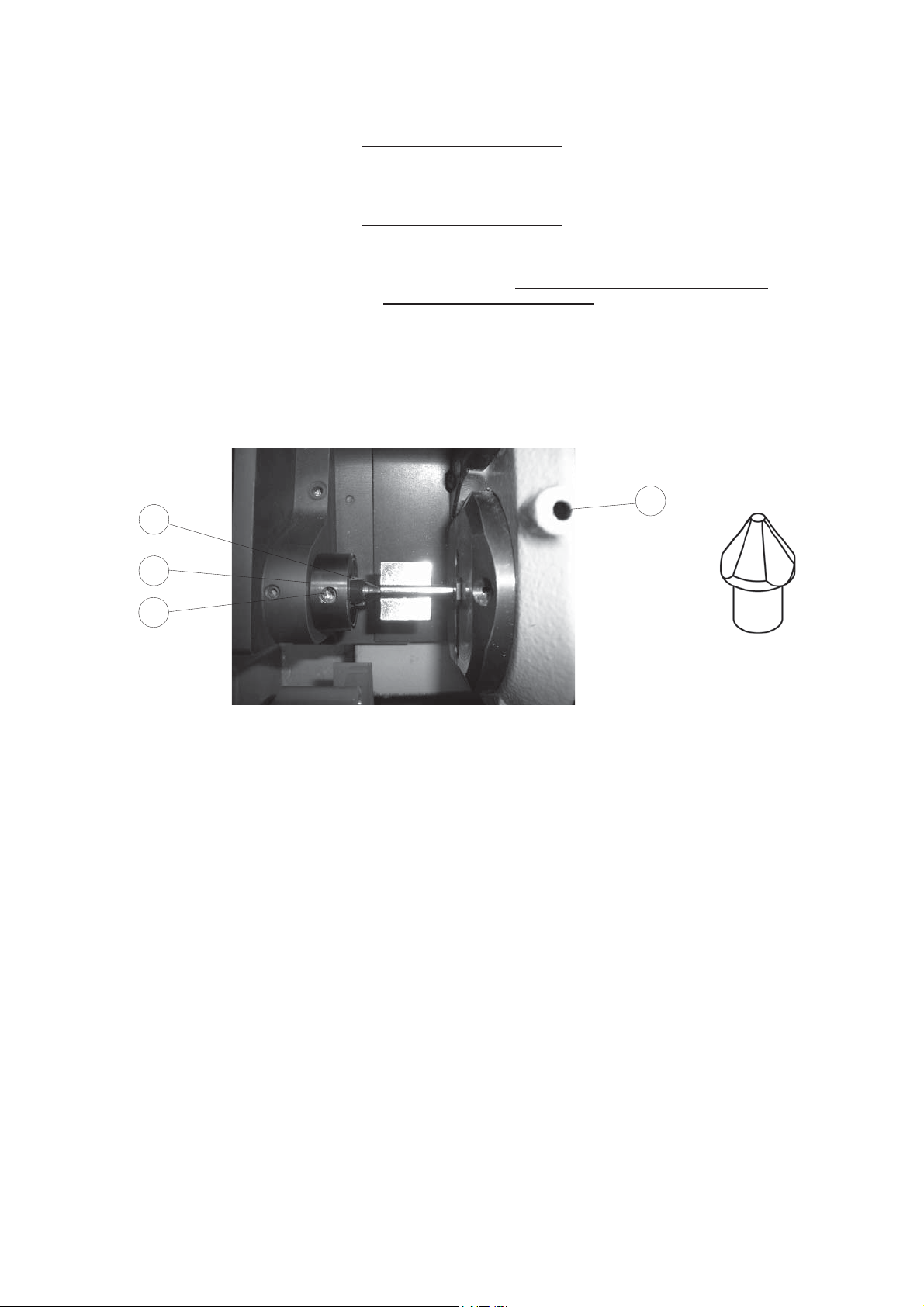
The key blank to be cut must be positioned according to the parameters given on the display after selecting
the program involved; the type of key with front stop requires the use of the rotating clamp (S1), the ‘K1’
tailstock, the E2 adapter and the key reference on “Stop 0”.
Please follow the instructions below carefully, and observe the order of operations.
E2
K1
V2
V1
E2
Fig. 31
1) Loosen the knob (T1) by turning it anticlockwise until the rotating clamp (S1) can be moved to a convenient
distance for fitting the key.
2) Fit the adapter E2 into the tailstock K1 up against the mechanical stop (T).
ATTENTION: the adapter E2 must be properly fitted into its seat and pressed up against the stop point.
3) Take the T wrench (T4) from its seat and open the rotating clamp jaws by turning the sunk hex. screw
(V1); at the end of the operation leave the T wrench in the screw (V1).
4) Fit the key blank into the front side of the rotating clamp (G) and position it on the groove in the jaws, then
take the key forward until the adapter E2 goes into the hole in the stem.
5) Close the mobile clamp jaws slightly, using the T wrench already in the screw (V1), without gripping the
key stem; move the rotating clamp (G) towards the tailstock, keeping a minimum safety distance of 10 mm
between the rotating clamp jaws and the rear limit of the bit. Secure the rotating clamp in position by
means of knob (T1).
6) Hold the key head in the left hand and align crosswise, making sure that the bit is all the way up against
the adapter E2 on the tailstock (K1), then close the grips round the key stem, using the T wrench (T4)
already in place on the screw (V1).
7) Transfer the T wrench (T4) onto the screw (V2) of the tailstock and secure the adapter E2.
8) Replace the T wrench in its seat, lower the mobile safety shield and begin the process with START.
To remove the key after cutting, carry out the operations described, in reverse order.
Copyright Silca 2004 27
Page 32
IDEA Operating Manual - English
Cutting in progress
Copy: 1 of: 1
Copy: 1 of: 1
finished
More copies ?
No=STOP Yes=ENTER
You can now press ENTER in order to make further copies of the previously read original key.
5.6 C
OPY FROM
Clamp: S100 A-B=
Stop 0 =
ORIGINAL
reference or point for positioning the key in the reading clamp.
FOR
CENTRE STOP
Clamp: S100 A-B Stop: 0
[START]
indicates the clamp (
Original on right
S100
) into which the key must be fitted, and which jaws to use.
5.6.1 Reading keys with centre stop (English type)
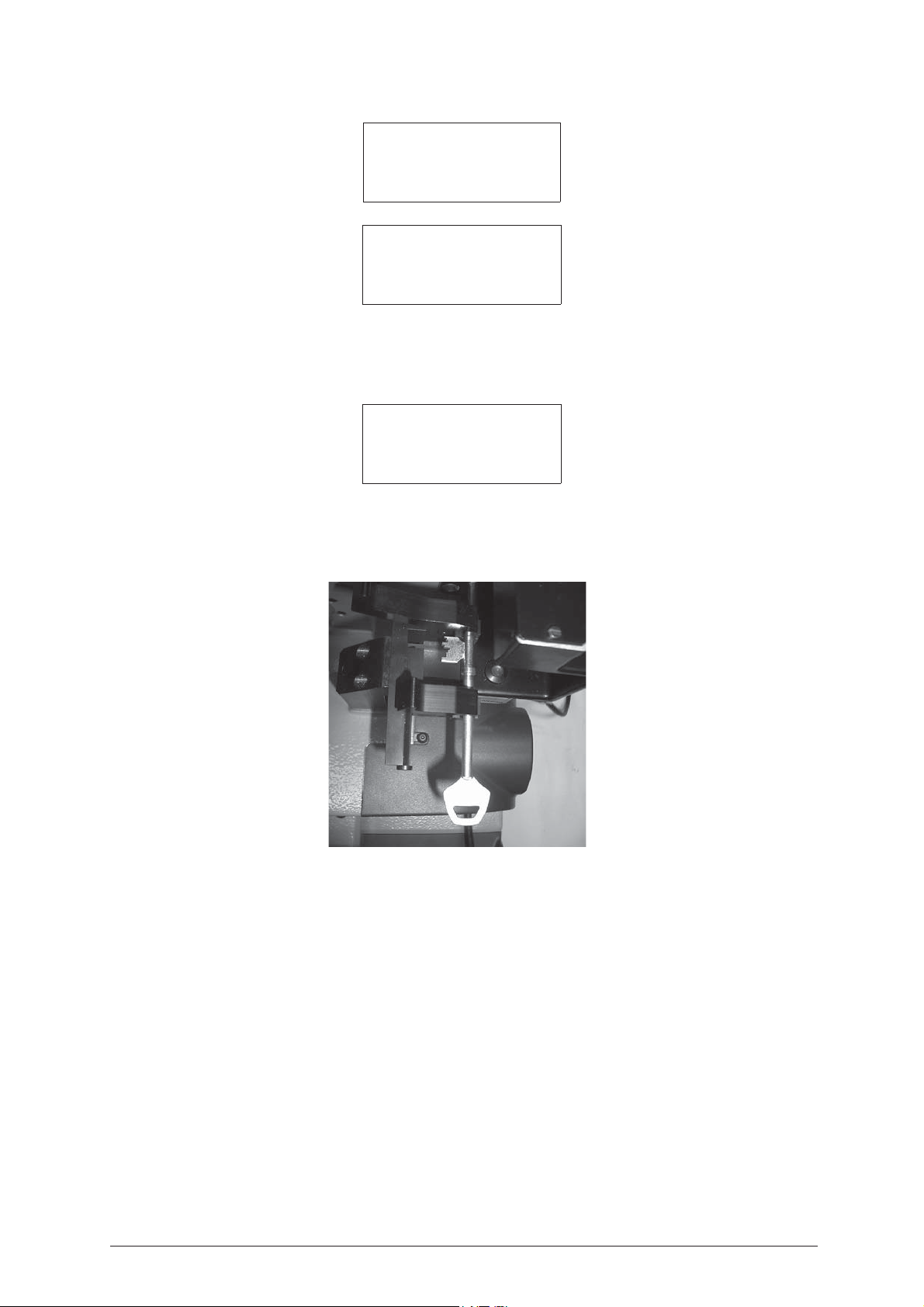
Fig. 32
1) Open the fixed clamp (A) and the mobile clamp (B) by pressing on the grip lever.
2) Fit the key into the special groove (axis X1) taking the bit up against the fixed clamp (A).
ATTENTION: position the key so that the highest tooth is facing left, ensuring contact with the stop (0) on the
vertical side of the tooth.
3) Release the grip lever.
4) Place the mobile clamp (B) in position on the key stem at a minimum distance of 3 mm from the end of
the collar.
5) When the reading process is started the carriage takes the key into contact with the laser beam along the
path and in the direction indicated by the broken line.
6) At the end of the cycle see the message on the display in order to continue (see ch.5.6.2).
28 Copyright Silca 2004
Page 33

Operating Manual - English IDEA
Reading in progress…
Data processing
in progress
Please wait…
Press START to proceed with cutting the key (see ch.5.6.2).
5.6.2 Cutting keys with centre stop (English type)
Left blank Brass
Clamp: S1-K1 Stop:1
Cutt.: 1.25 Adap.: E1
Pcs. = 1/1 [START]
Clamp: S1- K1 =
Stop 0 =
reference or point for positioning the key in the cutting clamp.
Cutter: 1.25 =
Adapt.: E1 =
Brass/Steel =
indicates which clamp (
S1)
and tailstock (K1) to use for gripping the key.
thickness of the currently selected cutter (press SHIFT+ENTER to change thickness).
special adapter for keys with CENTRE STOP.
material of the key (press SHIFT+ ? to change material).
ATTENTION: always check that the wording corresponds to the material of the key.
The key blank to be cut must positioned according to the parameters given on the display after selecting the
program involved; the type of key with centre stop requires the use of the E1 adapter and the key reference
on “Stop 0”.
Please follow the instructions below carefully, and observe the order of operations.
1) Loosen the knob (T1) turning it anticlockwise until the rotating clamp (S1) can be drawn back and secured
at the end of its external run (mechanical stop).
2) Take the T wrench (T4) from its seat and fit into the screw (V1), then loosen until the jaws are fully open.
At the end of the operation do not remove the T wrench from the screw (V1).
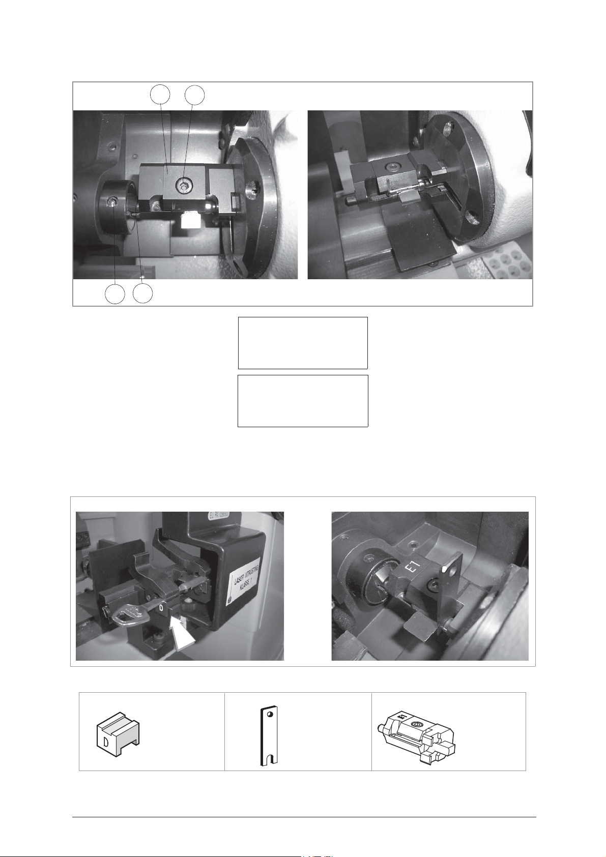
3) Fit the key blank into the adapter E1, taking care that it is in the right position (fig. 33), then tighten the
screw (V4).
4) Fit the adapter E1 with the key blank in the inner side of the rotating clamp (S1), take the adapter up
against the face of the self-centring jaw and use the T wrench (T4) to slightly close the jaws on the rotating
clamp.
5) Move the rotating clamp S1 so that the adapter E1 enters the tailstock K1.
6) Tighten the knob (T1).
Use the T wrench (T4) to tighten the screw (V1) first, then the screw (V2).
Replace the T wrench (T4) into its seat, lower the mobile safety shield and begin the process with START.
To remove the key after cutting, carry out the same operations, in reverse order.
Copyright Silca 2004 29
Page 34
IDEA Operating Manual - English
Reading / decoding
Cutting
Fig. 33
V2
E1
K1
V4
Cutting in progress
Copy: 1 of: 1
Copy: 1 of: 1 finished
More copies ?
No=STOP Yes=ENTER
You can now press ENTER in order to make further copies of the key.
5.7 FAS 309 P
ONLY DECODE AND COPY
Fig. 34
LASTIC STEM
OPTIONALOPTIONAL OPTIONAL
D711802ZB D727058ZBD727713ZB
Spacer Adapter E1Adapter D
Fig. 35
30 Copyright Silca 2004
Page 35
Operating Manual - English IDEA
X1
Y1
A1
Y2
A2
G
5.8 A
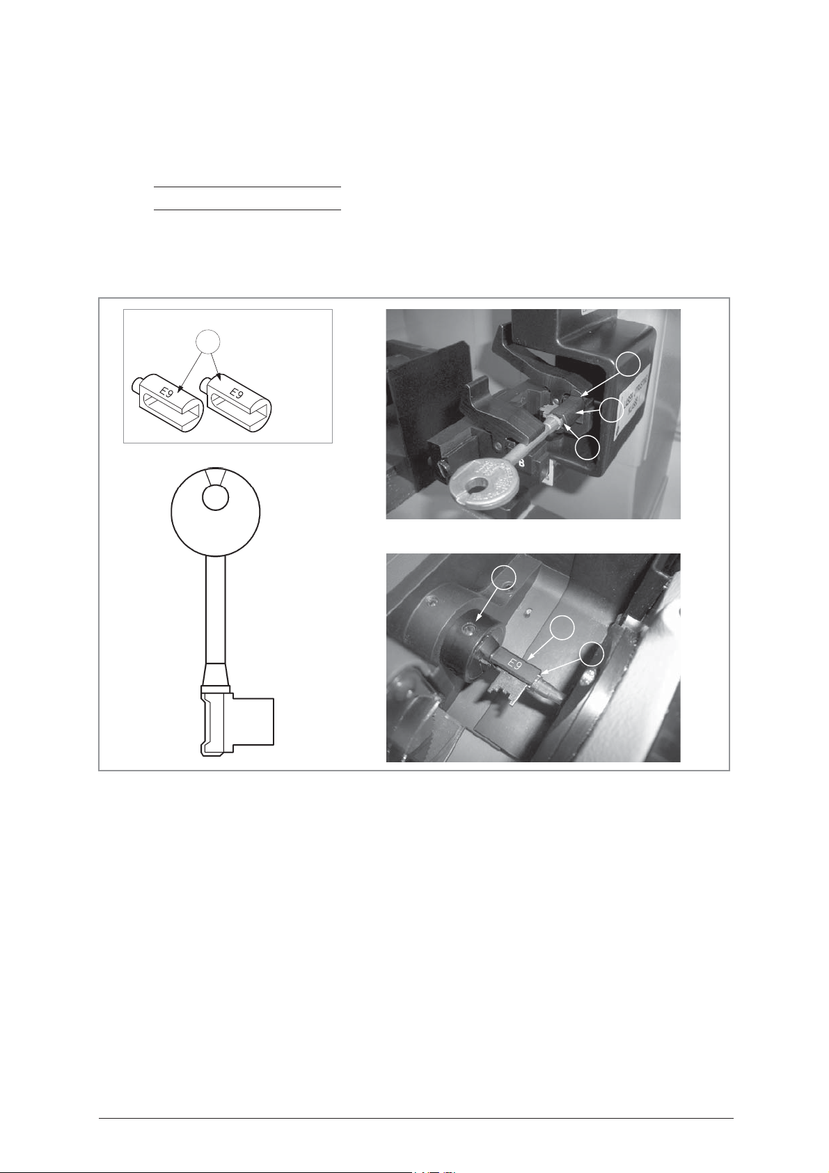
The Chubb adapter set is required for the code-cutting of Chubb keys (CHUBB RKS) with square section
stems (fig. 36). It comprises 2 identical adapters (A) for the optic reader clamp and the swivel clamp.
1) Fit adapter (A1) into the groove on the optic reader clamp, take it up against the stop (X1).
2) Place the key to be decoded in its place on the adapter, which must butt against the key rim (Y1).
NOTE: place the key so that the bit is as horizontal as possible.
3) Place the second adapter (A2) into the standard tailstock and tighten the grub screw (G) (fig. 36).
4) Place the key to be cut into its seat on the adapter, which must butt up against the key rim (Y2); take the
5) Proceed with the cutting operation.
DAPTER FOR CUTTING
rotating clamp up to the stem and secure the key.
CHUBB
KEYS WITH SQUARE SECTION STEMS
OPTIONAL
A
D716544ZB
Adapters E9
Fig. 36
Copyright Silca 2004 31
Page 36
IDEA Operating Manual - English
5.9 PUMP KEYS
OPTIONAL
D726180ZB
Adapters
Fig. 37
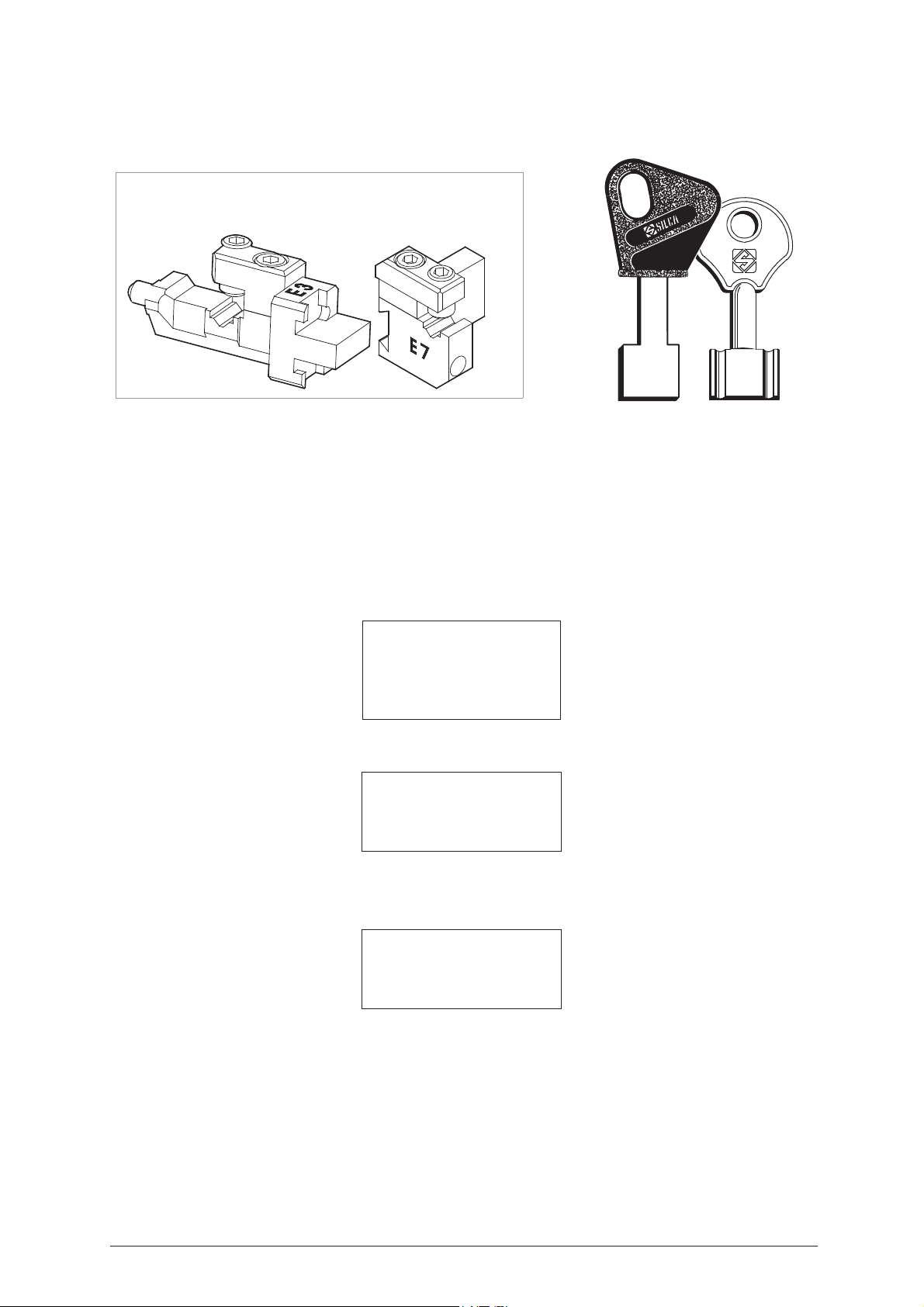
E3
Adapter for pump keys (E3 - ID), used for cutting (install between the rotating S1 and K1 tailstock).
E7
Adapter for pump keys (E7 - ID), used for reading (install in the place of the S100 - B mobile clamp).
E3
When the machine requires (indicates on display) adapter
following examples:
- It is very important to distinguish the type of key to be copied. Choose
SELECT TYPE OF KEY
0 - Bit stop male
1 - Bit stop female
2 - Shoulder stop
3 - Pump
- Choose
option 1
- Reading + Copy
1 - Reading + Copying
2 - Cutting only
3 - Reading only
4 - Post-reading adj.
or E7, proceed in the way described in the
option 3
- Pump.
READING PUMP KEYS
KEY READING
Original on right
Clamp: S100 A Stop: 0
Adapt: E7 [START]
32 Copyright Silca 2004
Page 37
Operating Manual - English IDEA
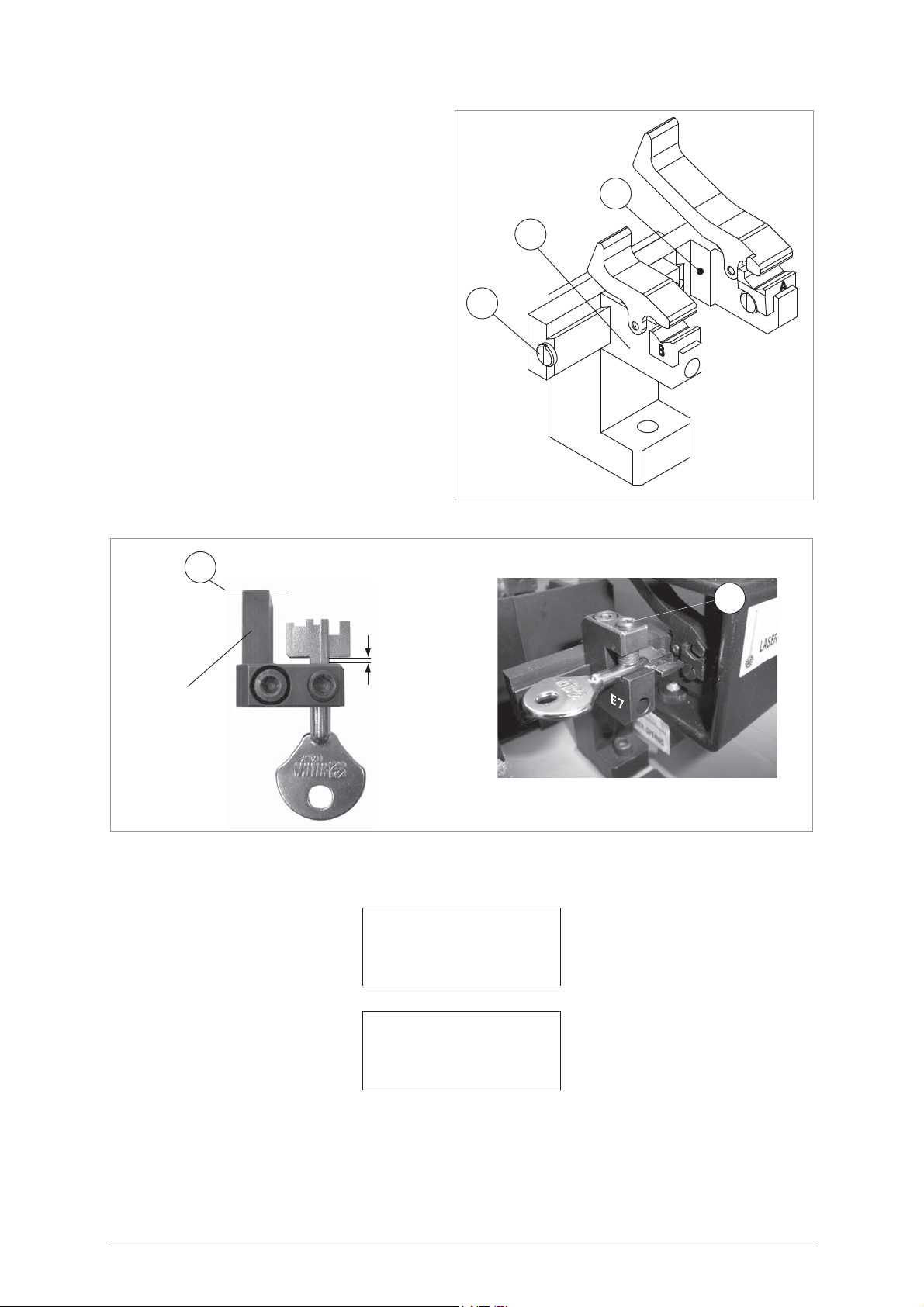
Operate as follows:
1) Loosen the screw (G) 1)on the S100
clamp.
2) Pull out the mobile clamp unit (B).
3) Fit the
4) Fit the original key into the
E7
adapter into the S100 clamp,
then tighten the screw (G).
E7
adapter so
that the key stem (rectangular or round)
Y1
B
fits perfectly into its seat. The key head will
protrude from the side marked E7,
whereas the bit will fit inside the adapter,
not in contact with the stop but at approx.
2-3 mm. (fig. 39). When this condition is
G
reached, tighten the grub screw (C) to
secure the key.
5) Push the
E7
adapter until the side (Y) is
butting against the fixed part of the S100 A clamp.
6) Press the START key to continue.
7) When the reading process starts the
carriage will take the key into contact with
the laser beam along an ideal path.
Fig. 38
Fig. 39
Y
C
2-3 mm
Adapter E7
- At the end of the cycle see the message on the display in order to continue.
Reading in progress…
Data processing
in progress
Please wait…
Copyright Silca 2004 33
Page 38
IDEA Operating Manual - English
E
3
V1
V1
V2
E
3
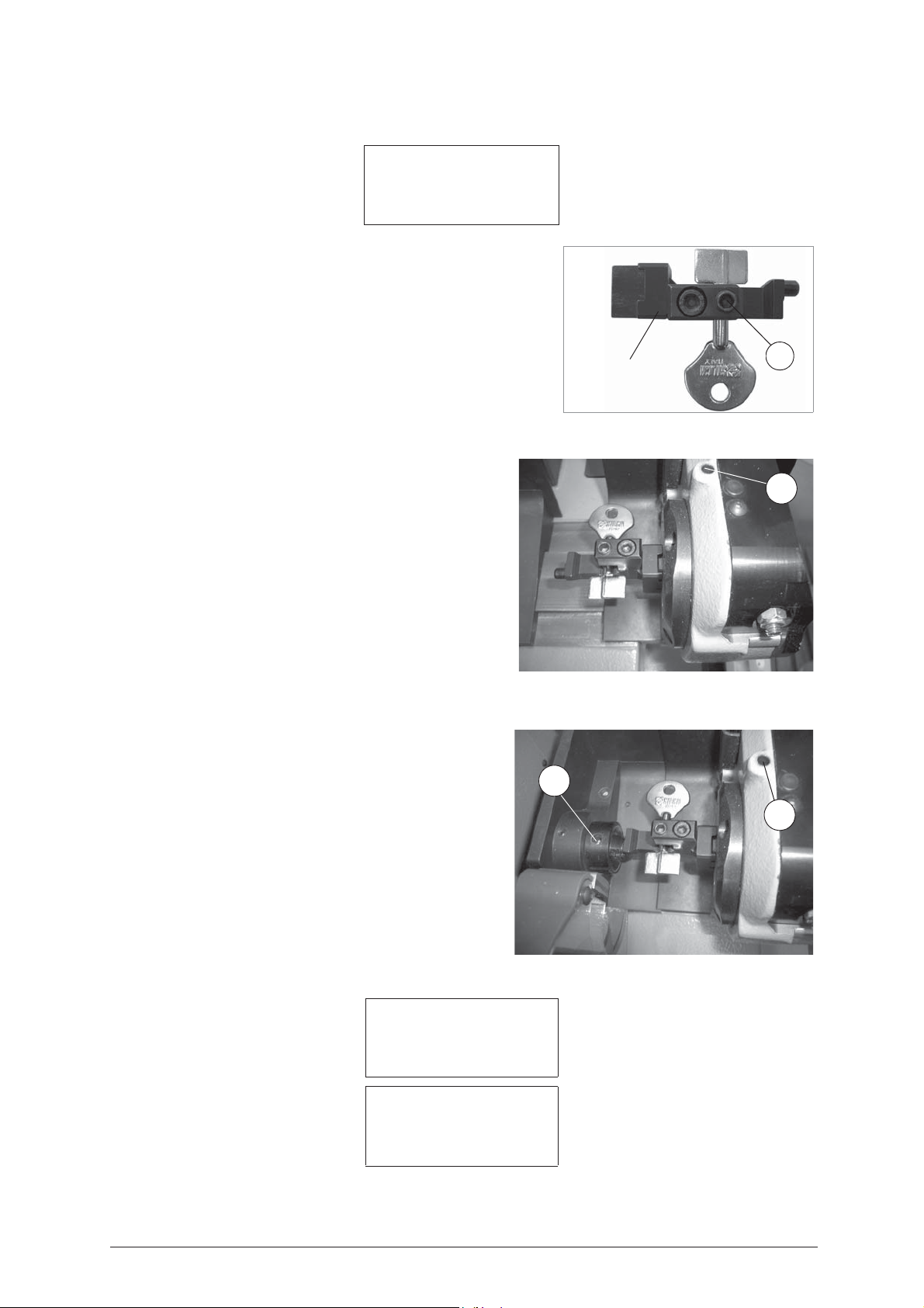
CUTTING PUMP KEYS
Left blank Brass
Clamp: S1-K1 Stop:3
Cutt.: 1.25 Adapt.: E3
Pcs = 1/1 [START]
Operate as follows:
Clamp: S1 - K1
to use for gripping the key.
Stop 0
= reference or positioning point on the key cutting clamp.
Cutter: 1.25
SHIFT+ENTER to change thickness).
Adatt: E3
Brass/Steel
material).
ATTENTION: always check that the wording corresponds to the
material of the key.
The key blank to be cut must be positioned according
to the parameters given on the display after selecting
the program involved; the type of pump keys requires
the use of the
"
Stop 3
".
Please follow the instructions below carefully, and
observe the order of operations.
1) Loosen the knob (T1) by turning it anticlockwise
until the rotating clamp (S1) can be moved to a
convenient distance for fitting the key).
2) Take the ‘T’ wrench (T4) from its seat and fit into the
screw (V1), then loosen until the jaws are fully open.
At the end of the operation do not remove the ‘T’
wrench from the screw (fig. 41).
3) Fit the key blank into the E3 adapter, paying
attention to its position (fig. ), then tighten the screw
(P).
4) Fit the
clamp (S1) from the inside, take the adapter up to
the side of the self-centring jaws and slightly close
the grips on the rotating clamp with the ‘T’ wrench
(T4).
5) Move the rotating clamp S1 so that the adapter
enters the tailstock K1.
6) Tighten the knob (T1). Use the ‘T’ wrench (T4) to
tighten the screw (V1) first, then the screw (V2) (fig.
42). Replace the T wrench (T4) into its seat, lower
the mobile safety shield and begin the process with
START.
- To remove the key at the end of the cutting process,
carry out the same operations in reverse order.
= indicates which clamp (S1) and tailstock (K1)
= thickness of the cutter currently selected (press
= special adapter for cutting PUMP keys.
= material of the key (press SHIFT+? to change
E3
adapter and the key reference on
E3
adapter, with the key blank in the rotating
E3
Adapter E3
P
Fig. 40
Fig. 41
Fig. 42
Cutting in progress
Copy: 1 of: 1
34 Copyright Silca 2004
- You can now press ENTER in order to make further copies of the key.
STOP
- Select
to quit.
Copy: 1 of: 1 finished
More copies ?
No=STOP Yes=ENTER
Page 39
Operating Manual - English IDEA
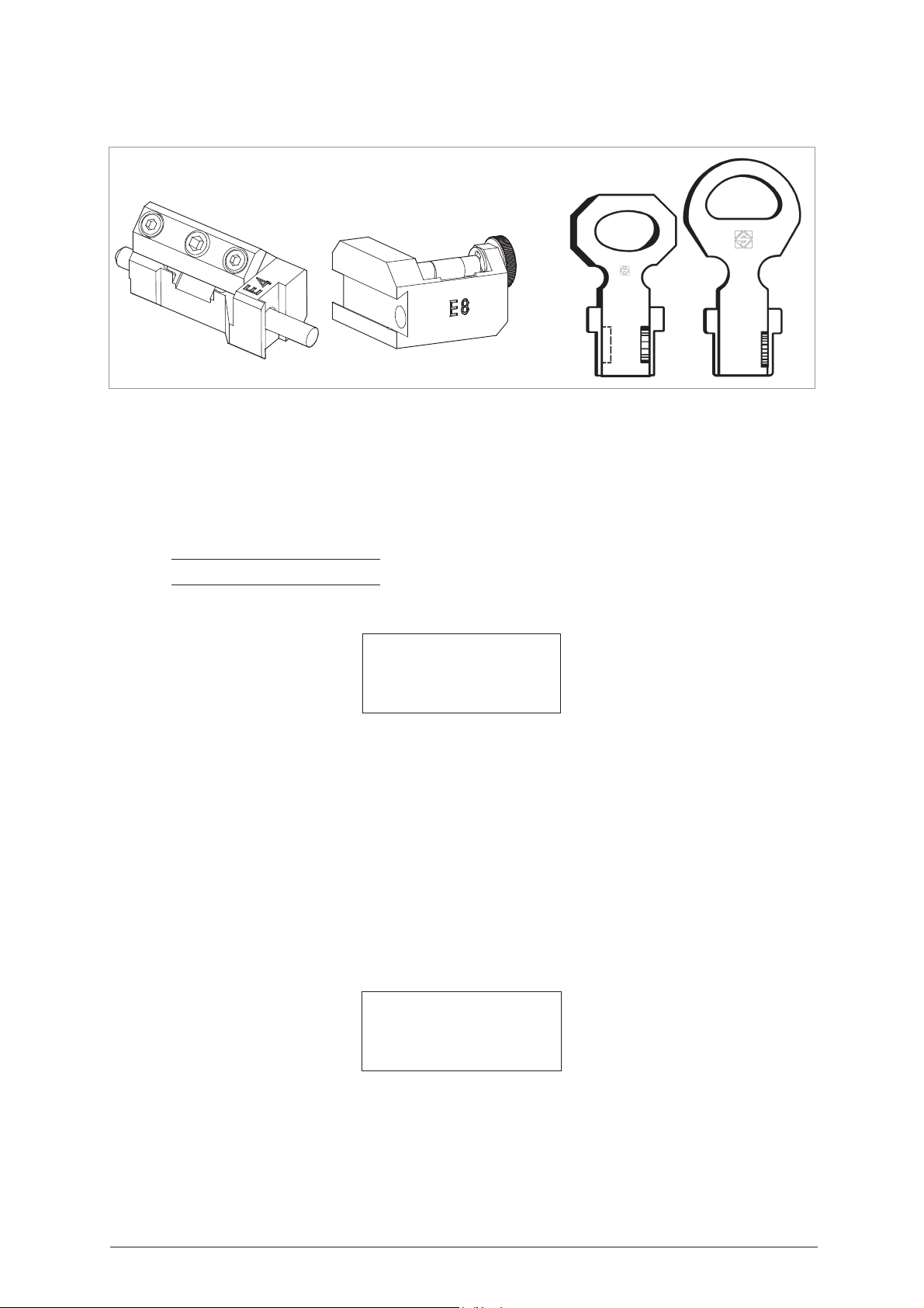
5.10 MUEL PUMP KEYS
OPTIONAL
D726465ZB
Fig. 43
THE SET COMPRISES:
E4
Adapter for Muel pump keys (E4 - ID), used for cutting (install between the rotating S1 and K1 tailstock).
E8
Adapter for Muel pump keys (E8 - ID), used for reading (install in the place of the S100 - B mobile clamp).
Adapters
Note: operations allowed only when decoding using SN 328 / SN 329 / SN 352
When the machine requires (indicates on display) adapter E4 or E8, proceed as in the example
0 - Copy from original
1 - Decode and Copy
2 - Insert the cuts
3 - Queue from PC
- Choose
- Choose the SN required (SN328 / SN329 / SN352...) and proceed.
To read Muel keys, proceed as follow
option 1
- “Decode and Copy”
:
READING MUEL PUMP KEYS
DECODE SSN 328
Original on right
Clamp: S100 Stop: 4
Adapt:
E8
[START]
.
Copyright Silca 2004 35
Page 40
IDEA Operating Manual - English
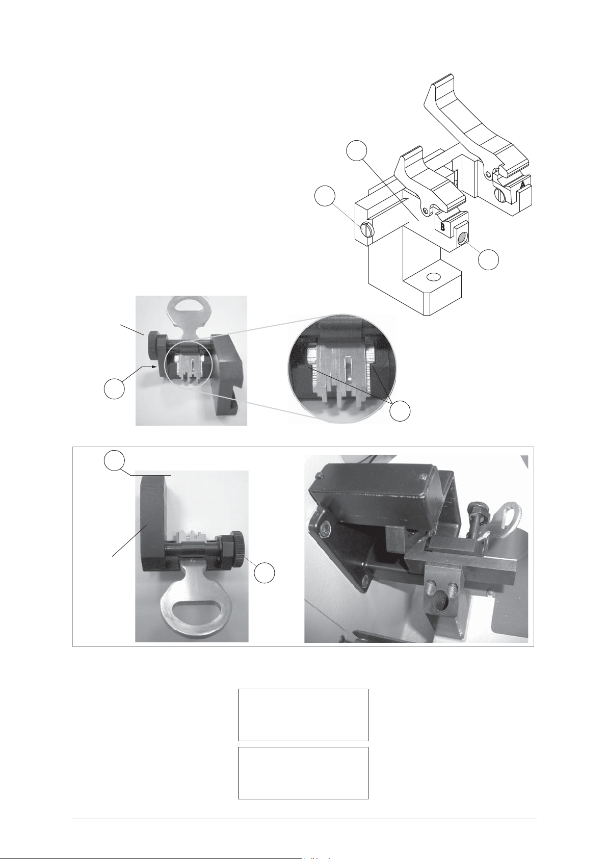
Adapter E8
P6
B9
Adapter E8
Y
P5
1)Loosen the screw (G) 1)on the S100 camp.
2)Pull out the mobile clamp unit (B).
3)Fit the
4)Fit the original key into the adapter
5)Push the
6)Press the START key to continue.
7)When the decode process starts the carriage
E8
tighten the screw (G).
the stops on the bit butt against the stops (P6)
on the adapter
upwards. From this condition turn the knob (P5)
to turn the pin-cam securing the key.
against the fixed part of the S100 - A clamp,
tighten the grub screw
will take the key into contact with the laser beam
along an ideal path.
adapter into the S100 clamp, then
E8
, so that
E8
and the cuts are directed
E8
adapter until the side (Y) is butting
(B9).
B
G
B9
Fig. 44
Fig. 45
8)At the end of the cycle see the message on the display in order to continue.
Decoding in progress…
Bit 1
Bit 1
5 3 1 0 2 5 4 3 2 4
36 Copyright Silca 2004
Possible depths:
0 1 2 3 4 5 [10]
Page 41
Operating Manual - English IDEA
Adapter E4
P
P7
V1
V2
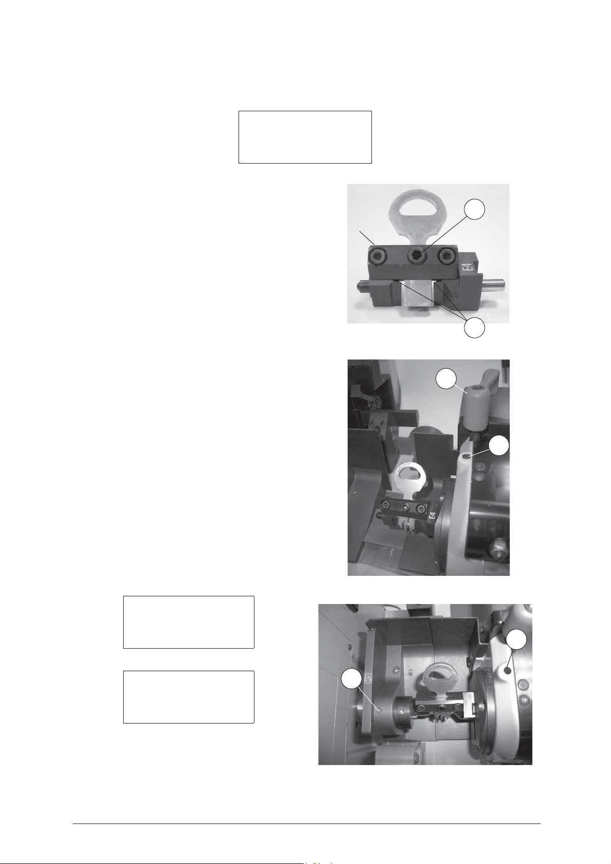
To cut Muel keys, proceed as follow
:
CUTTING MUEL PUMP KEYS
SSN 328 M1 Brass
Clamp: S1-K1 Stop:0
Cutt : 1.25 Adapt: E4
Pcs. = 1/1
The key blank to be cut must be positioned according to
the parameters given on the display after selecting the
program involved; the type of Muel pump keys requires
the use of the
".
0
adapter and the key reference on "
Stop
E4
Please follow the instructions below carefully, and
observe the order of operations.
1)Loosen the knob (T1) by turning it anticlockwise until
the rotating clamp (S1) can be moved to a convenient
distance for fitting the key).
2)Take the ‘T’ wrench (T4) from its seat and fit into the
screw (V1), then loosen until the jaws are fully open.
At the end of the operation do not remove the ‘T’
wrench from the screw (fig. 47).
Fig. 46
3)Fit the key blank into the adapter E4 so that the bit
stops butt against the
E4
adapter stops (P7) (fig. 46);
tighten the screw (P).
4)Fit the
E4
adapter, with the key blank in the rotating
clamp (S1) from the inside, take the adapter up to the
side of the self-centring jaws and slightly close the
grips on the rotating clamp with the ’T’ wrench (T4).
5)Move the rotating clamp S1 so that the adapter
E4
enters the tailstock K1.
6)Tighten the knob (T1). Use the T wrench (T4) to
tighten the screw (V1) first, then the screw (V2) (fig.
46). Replace the T wrench (T4) into its seat, lower the
mobile safety shield and begin the process with
START.
- To remove the key at the end of the cutting operation:
loosen the grub screw (P) and remove the key,
or carry out the operations described above, in
reverse order.
Fig. 47
T1
E
3
V1
Cutting in progress
Copy: 1 of: 1
Bit 1
Copy 1 of 1 finished
More copies ?
NO=Stop YES =Enter
- You can now press ENTER in order to make further
copies of the key.
- Select
STOP
to quit.
Fig. 48
Copyright Silca 2004 37
Page 42
IDEA Operating Manual - English
stem
SQUARE
stem
SQUARE-ROUND
stem
SPECIAL SQUARE
D726462ZB
Adapters
OPTIONAL
**
5.11 FIAM KEYS
Fig. 49
(*) WITH OPTIONAL
E5
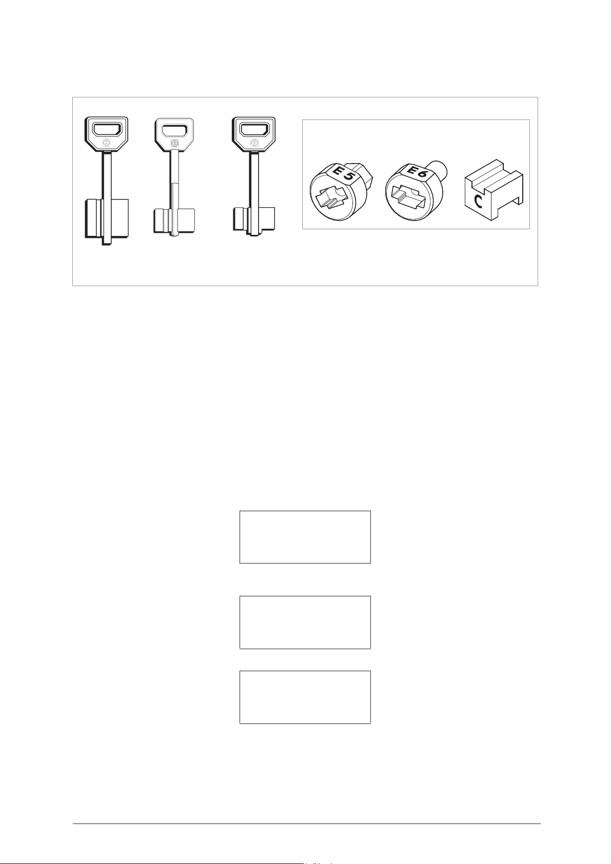
Centring device for FIAM keys (E5 - ID), used in cutting (install on the K1 tailstock) (Special Square Stem).
E6
Centring device for FIAM keys (E6 - ID), used in reading (install on the fixed clamp S100-A).
C
Adapter for FIAM keys (C - ID), used in reading (install on clamp S100 in the place of jaw B), (Square-Round
Stem and Special Square Stem).
When the machine requires (indicates on display) adapter
the following examples:
- It is very important to distinguish the type of key to be copied:
SELECT TYPE OF KEY
0 - Bit stop male
1 - Bit stop female
2 - Shoulder stop
- Choose
for keys with special square stems (step on tip).
- Choose
option 4
option 1
for keys with square stems;
3 - Pump
4 - Square-square tip
5 - Square-round tip
6 - Square-stepped tip
- Reading + Cutting
option 5
E5
or E6 or C, proceed in the way described in
for keys with square and round stems;
option 6
1 - Reading + Copying
2 - Cutting only
3 - Reading only
4 - Post-reading adj.
38 Copyright Silca 2004
Page 43

Operating Manual - English IDEA
KEYS READING
READING SQUARE STEMMED FIAM KEYS
KEY READING
Original on right
Clamp:S100 A-B Stop: 0
[START]
Operate as follows:
See Operating Manual, as for keys with front stop M.
Fig. 50
READING SQUARE AND ROUND STEMMED FIAM KEYS
KEY READING
Original on right
Clamp: S100 A-C Stop: 0
[START]
Operate as follows:
1) Press the grip on the S100-B1 mobile clamp and
remove the adapter (jaw B).
2) Install jaw C so that the letter C is facing the
operator.
3) Open the fixed clamp (A) and the mobile clamp (C)
by exerting pressure on the jaw lever (F) and (F1).
4) Fit the key into the special groove taking the bit all
the way into the fixed clamp (A).
ATTENTION: position the key so that the highest tooth is
facing left, ensuring contact with the stop (0) on
the vertical side of the tooth.
5) Release the jaw lever.
6) Place the mobile clamp (C) in the best position on
the stem between the bit and key head. Make sure
that there is a distance of min. 3 mm and max. 15
mm between the bit and inside of the mobile clamp
(C) (the square part of the stem should butt against
jaw C).
7) When the reading process starts the carriage will
take the key into contact with the laser beam along
the path dictated by the Software.
At the end of the cycle see the message on the display
in order to continue.
F
F1
Fig. 51
Copyright Silca 2004 39
Page 44
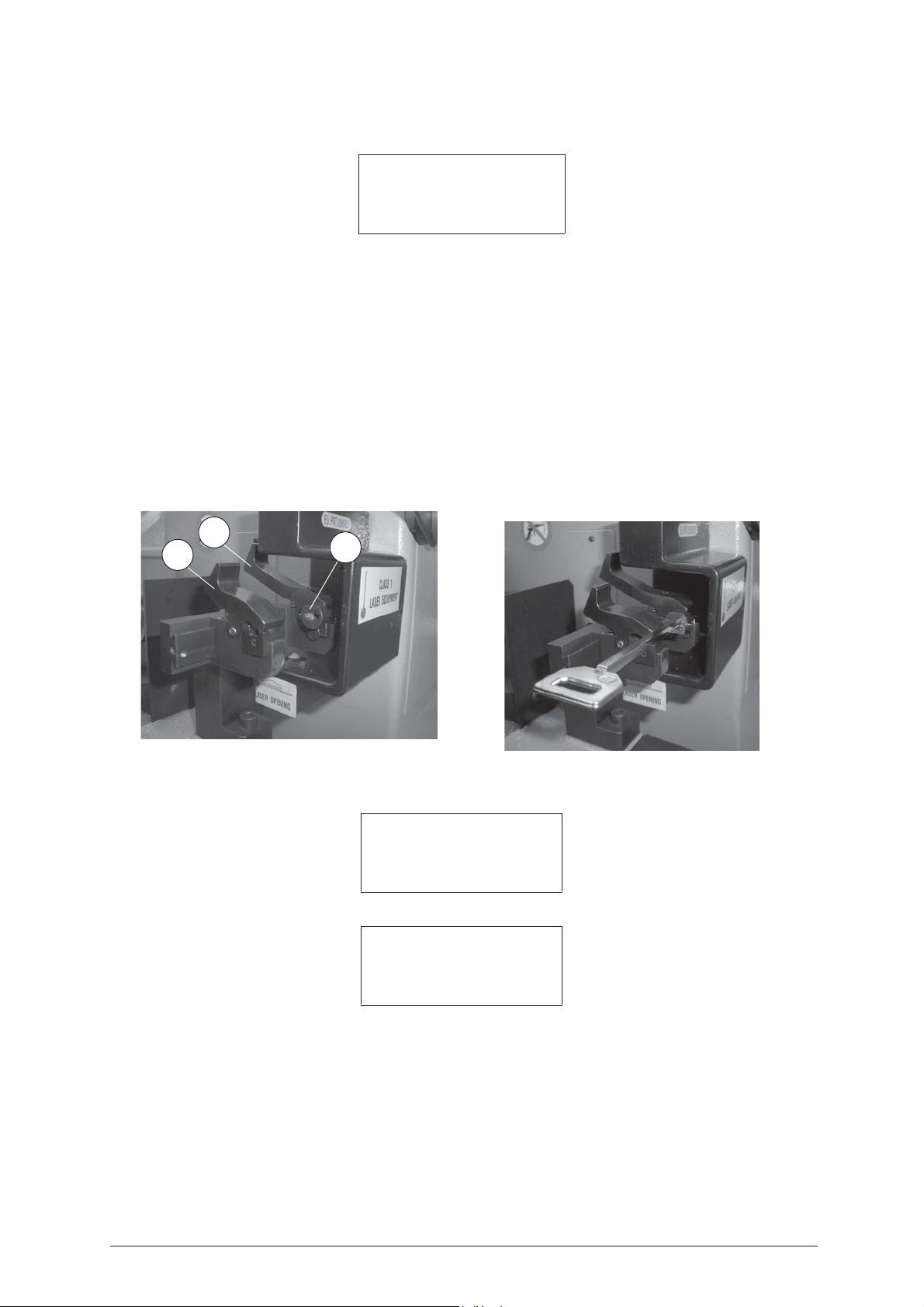
IDEA Operating Manual - English
READING SPECIAL SQUARE STEMMED FIAM KEY (WITH STEP)
KEY READING
Original on right
Clamp:S100 A-C Stop: 0
[START]
Operate as follows:
1) Press the grips on the S100-B mobile clamp and remove the adapter (jaw B) (fig. 52).
2) Install jaw C so that the letter C is facing the operator (fig. 52).
3) Open the fixed clamp (A) by pressing on the grip lever (F) and fit the
that it butts against jaw A and the initials
4) Press on the lever grip (F1) and fit the key into its seat so that the bit is up against the fixed clamp (E6)
(fig. 53).
ATTENTION: position the key so that the highest tooth is facing left, ensuring contact with the stop (0) on the
vertical side of the tooth.
5) Release the jaw lever.
6) Press START to proceed.
7) When the reading process starts the carriage will take the key into contact with the laser beam along an
ideal path.
At the end of the cycle see the message on the display in order to continue.
E6
are upwards.
E6
adapter on the S100-A clamp so
Fig. 52
F1
F
E6
Fig. 53
Reading in progress…
Data processing
in progress
Please wait…
40 Copyright Silca 2004
Page 45
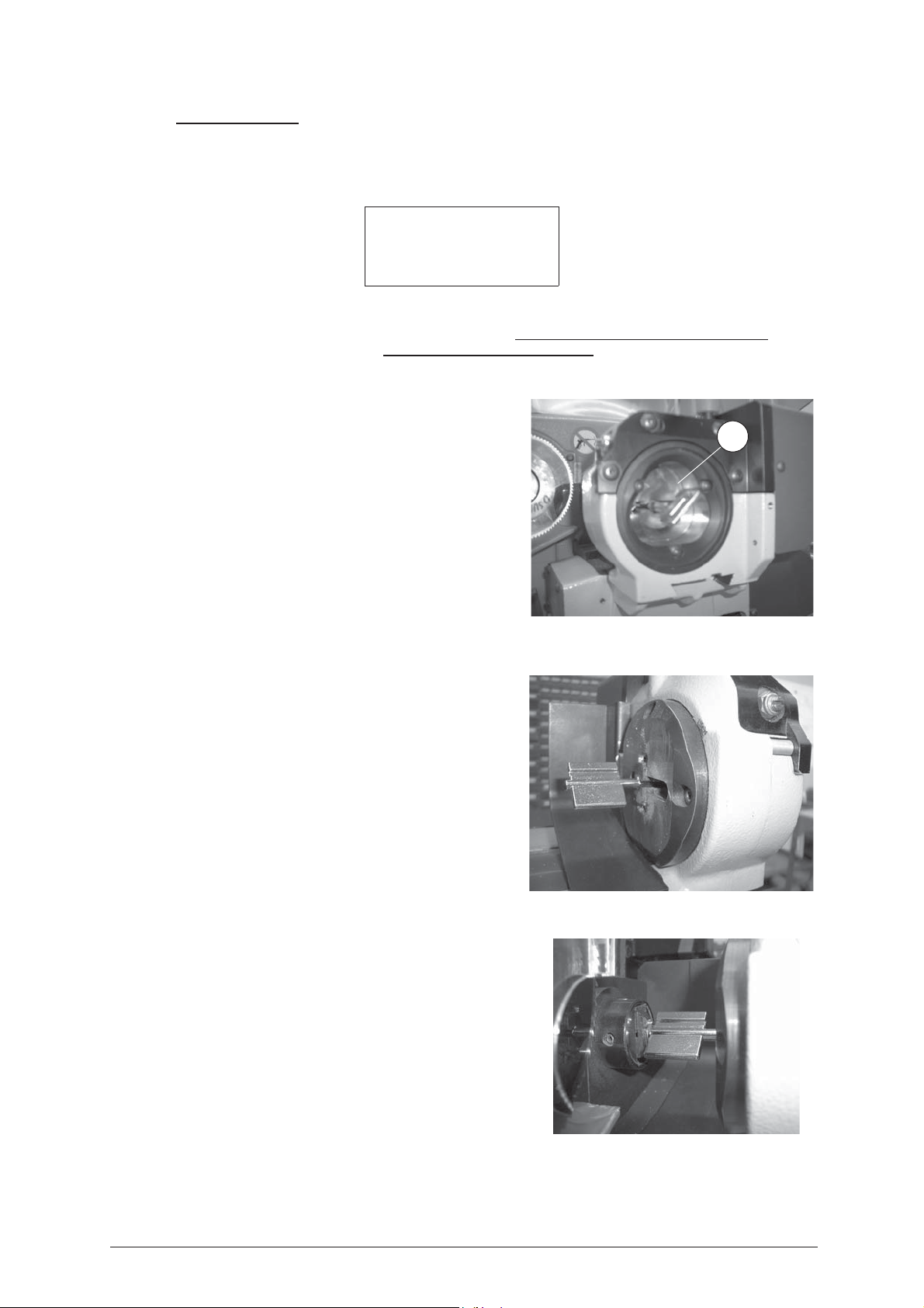
Operating Manual - English IDEA
CUTTING KEYS
CUTTING FIAM KEYS WITH SQUARE STEM
CUTTING FIAM KEYS WITH SQUARE-ROUND STEM
Left blank Brass
Clamp: S1-K1 Stop:0
Cutt.: 1.25
Pcs. = 1/1 [START]
Clamp: S1- K1 =
Stop 0 =
Cutter: 1.25 =
Brass/Steel =
ATTENTION: always check that the wording corresponds to the material of the key.
The key blank to be cut must be positioned according to
the parameters given on the display after selecting the
program involved; the type of key with front stop requires
the use of the rotating clamp (S1), the “K1” tailstock
support and the key reference on “Stop 0”.
Please follow the instructions below carefully, and
observe the order of operations.
1) Loosen the knob (T1) by turning it anticlockwise until
2) Orient the standard tailstock (K1) for male keys in the
3) Take the ‘T’ wrench (T4) from its seat and open the
4) Fit the key blank into the rotating clamp (S1) from the
5) Close the mobile clamp jaws slightly, using the T
reference or positioning point on the key cutting clamp.
the rotating clamp (S1) can be moved to a convenient
distance for fitting the key.
special seat on the support, using the screw (V2) to
direct it upwards.
rotating clamp jaws by turning the sunk hex. screw
(V1); at the end of the operation leave the T wrench in
the screw (V1).
front, positioning the square stem over the "V" on the
grips diagonally so that the left-hand bit is sloping
downwards (fig. 54 and fig. 55).
wrench already in the screw (V1), without gripping the
key stem; move the rotating clamp (G) towards the
tailstock, keeping a minimum safety distance of 10 mm
between the rotating clamp jaws and the rear limit of
the bit. Secure the rotating clamp in position by means
of knob (T1).
indicates which clamp (S1) and tailstock (K1) to use for gripping the key.
thickness of the cutter currently selected (press SHIFT+ENTER to change thickness)
material of the key (press SHIFT+ ? to change material)
S1
Fig. 54
6) Hold the key head with the left hand and push towards
the tailstock, making sure that the bits butt up against
the grips on the tailstock (K1); simultaneously transfer
the ‘T’ wrench (T4) onto the tailstock screw (V2) and
secure the key tip (fig. 56).
7) Transfer the ‘T’ wrench (T4) onto the screw (V1) and
tighten the grips on the key stem.
8) Replace the ‘T’ wrench in its seat, lower the mobile
safety shield and begin the process with START.
To remove the key after cutting, carry out the operations
described, in reverse order.
Copyright Silca 2004 41
Fig. 55
Fig. 56
Page 46
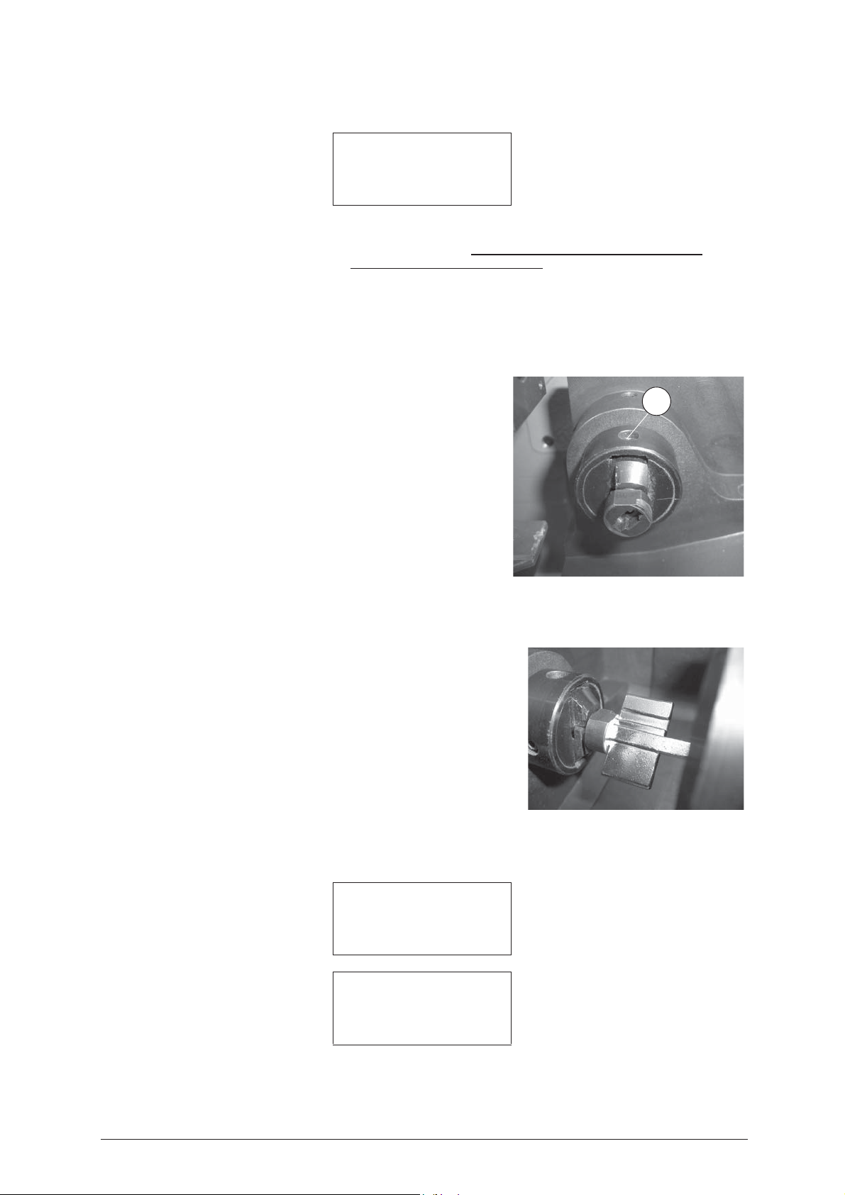
IDEA Operating Manual - English
CUTTING SPECIAL SQUARE STEMMED FIAM KEY (WITH STEP)
Left blank Brass
Clamp: S1-K1 Stop:3
Cutter: 1.25 Adap.:E5
Pcs = 1/1 [START]
Clamp: S1- K1 =
Stop 0 =
reference or positioning point on the key cutting clamp.
Cutter: 1.25 =
Brass/Steel =
E5 Adapter =
indicates which clamp (S1) and tailstock (K1) to use for gripping the key.
thickness of the cutter currently selected (press SHIFT+ENTER to change thickness)
material of the key (press SHIFT+ ? to change material)
indicates the adapter to fit into the K1 tailstock in order to position the key properly.
ATTENTION: always check that the wording corresponds to the material of the key.
The key blank to be cut must be positioned according to the parameters given on the display after selecting
the program involved; the type of key with front stop requires the use of the rotating clamp (S1), the ‘K1’
tailstock support and the key reference on “Stop 0”.
Please follow the instructions below carefully, and observe the order of operations.
1) Loosen the knob (T1) by turning it anticlockwise until the
rotating clamp (S1) can be moved to a convenient distance
for fitting the key.
2) Orient the standard tailstock (K1) for male keys in the special
seat on the support, using the screw (V2) to direct it
upwards.
3) Take the ‘T’ wrench (T4) from its seat and use on the screw
(V2) to open the K1 tailstock grips.
4) Fit the adapter
E5
into the K1 tailstock so that the initials
E5
are facing upwards and the adapter is butting well up against
the K1 tailstock grips (fig. 57).
5) Tighten the screw V2 with the (T4) wrench.
6) Take the T wrench (T4) from its seat and open the rotating
clamp jaws by turning the sunk hex. screw (V1); at the end
of the operation leave the T wrench in the screw (V1).
7) Fit the key blank into the rotating clamp (S1) from the front,
positioning the square stem over the "V" on the grips diagonally
so that the left-hand bit is sloping downwards (fig. 54 and fig.
55).
8) Use the ‘T’ wrench, already on the screw (V1), to slightly
tighten the grips on the rotating clamp, without exerting
pressure on the key stem; move the rotating clamp (G) towards
the tailstock, keeping a minimum safety distance of 10 mm
between the grips on the rotating clamp and the rear end of the
bit. Secure the rotating clamp by tightening the knob (T1).
9) Hold the key head with the left hand and push the key, making
sure that the bits butt up against the adapter
E5
installed on the
tailstock (K1); simultaneously close the grips on the key stem
by means of the ‘T’ wrench (T4) already on the screw.
V2
E5
Fig. 57
Fig. 58
Replace the T wrench in its seat, lower the mobile safety shield and begin the process with START. To
remove the key after cutting, carry out the operations described, in reverse order.
Cutting in progress
Copy: 1 of: 1
Copy: 1 of 1 finished
More copies ?
No=STOP Yes=ENTER
You can now press ENTER in order to make further copies of the key.
42 Copyright Silca 2004
Page 47
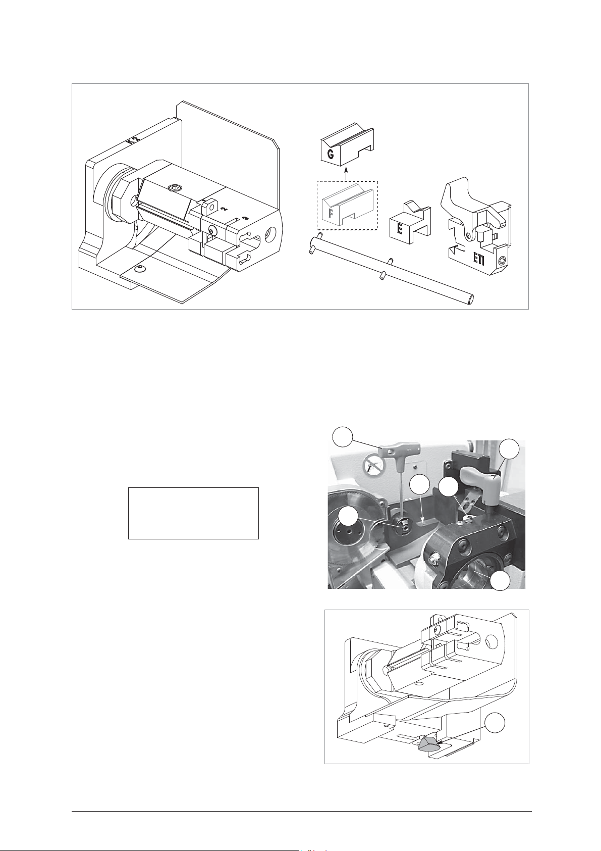
Operating Manual - English IDEA
W
T1
S1
K1
T4
V1
5.12 KEYS WITH REAR STOP (M
ALE KEYS AND FEMALE KEYS
)
OPTIONAL
D727498ZB
The set comprises:
K2
: Tailstock for keys with rear stop.
E11
: Adapter for reading (install on S100 clamp in place of S100-B mobile clamp).
E
: Adapter (E = ID initial), used for reading some types of keys (install on S100-E11mobile clamp) (see
Set for keys with rear stop
Z15
diagram "TYPE OF KEYS", page 47).
F / G
: Adapter (F or G = ID initial), used for reading some types of keys (install on S100-E11 mobile clamp
according to the type of key) (see diagram "TYPE OF KEYS", page 47).
Z15
: Template for gauging the cutting unit with K2 tailstock (Gauging – Cutting unit – Clamp S1-K2)
Note: before starting any operation for keys with rear
stops the K1 tailstock must be removed. Simply loosen the
screw (W) with the wrench (T4) (fig. 59) and push the K1
tailstock to the left in order to remove it from its seat.
If this is not done, an alarm will appear, even in the case of
a simple reading operation: ALARM 17
ALARM 17
Key origin
not found !
See operating manual
Fig. 59
To install K2 tailstock:
1) Loosen the knob (T1) by turning it anticlockwise until the
rotating clamp (S1) can be moved to the end of run towards
the operator, then use the (T4) wrench to tighten the rotating
clamp screw (V1) in order to close the self-centring jaws.
2) Fit the K2 tailstock into its seat, slightly inclined to the left, with
the fixing cam (C) (fig. 60) aligned with the slide runners and
secure by tightening the screw (W1) (fig. 67, page 48) with
the (T4) wrench.
3) Take the (S1) rotating clamp towards the K2 tailstock so that
they fit together perfectly, then secure by tightening the knob
(T1).
Note: use the (T4) wrench to loosen the screw (V1), in order
to open the jaws of the (S1) rotating clamp, exerting normal
pressure to secure the K2 tailstock firmly to the (S1)
rotating clamp.
Poceed with GAUGING.
Fig. 60
C
Copyright Silca 2004 43
Page 48
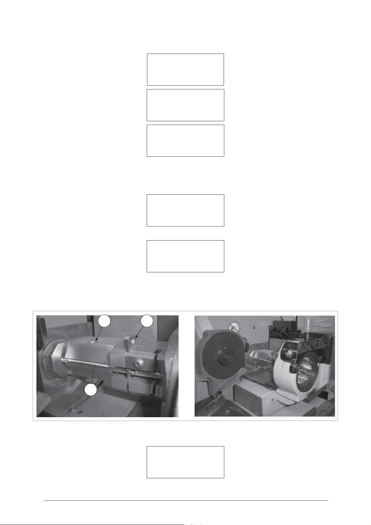
IDEA Operating Manual - English
- Use the arrow keys [up, down] to scroll.
1 - Clamps
2 - Cutter
3 - Adapter
Clamps
1 - S1 - Rotating Jaw
2 - S100 - Reading Jaw
Clamp: S1 - K1 >>
Adjustments: B=+000
X=+00 Y1=+00 Y2=+00
To calibrate [START]
- Press [SHIFT + ENTER]
Clamp: S1 - K1
>>
= press [SHIFT+ENTER] to go to the other interchangeable tailstocks used with the S1 clamp, if applicable.
Clamp: S1 - K2
= unit comprising the S1 clamp and K1 interchangeable tailstock
= unit comprising the S1 clamp and K2 interchangeable tailstock
Clamp: S1 – K2
Adjustments: B=+000
X=+00 Y1=+00 Y2=+00
To calibrate [START]
START
= press START to begin the automatic gauging procedure for the CLAMP TAILSTOCK unit.
Template Z13
Template Z15
Fig. 61
Clamp: S1 - K2
Install Z15 and Z13
See operating manual
[START]
= fit in place of the cutter (fig. 61).
=fit on the S1-K2 clamp as if it were a key (fig. 61). Use the plate (P) as a point of reference in
position 2 with the second pin on the template up against it. Tighten the screw (W2) with the
(T4) wrench. Replace the (T4) wrench in its seat.
W2
P
13
Z
Z15
Press START
Clamp: S1 - K2
Detection
In progress
44 Copyright Silca 2004
Page 49

Operating Manual - English IDEA
Clamp: S1 – K2
Adjustments: B=+000
X=+02 Y1=+02 Y2=+04
To calibrate [START]
Position the pointer at the side of the parameter to be edited with the arrow keys or [ENTER] and use the following keys
to edit the parameters:
[SHIFT] + [arrow up]: increases the value within
+ 300 hundredths of a mm or hundredths of a degree (axis B)
+ 20 cent.mm X/Y1/Y2
[SHIFT] + [arrow down]: decreases the value within
- 300 hundredths of a mm or hundredths of a degree (axis B)
20 cent.mm X/Y1/Y2
[CLEAR]: to zero the value
[ENTER]: in the last field to quit the window so that the query Save? appears for the edited data:
Save
adjustments ?
No=STOP Yes=ENTER
ATTENTION: if [STOP] is pressed the new measurements are not saved; the previous gauging values therefore
remain valid.
_ _ _ _ _ _ _ _ _ _ _ _ _ _ _ _ _ _ _ _ _ _ _ _ _ _ _ _ _ _ _ _ _ _ _ _ _ _ _ _
-
OPERATION FLOW
Choose
Choose
Choose
option 0 - Copy from Original
option 7 - Rear Stop
option 1
–
0 - Copy from Original
1 - Decode and Copy
2 - Insert cuts
3 - Queue from PC
SELECT TYPE OF KEY
0 - Bit stop male
1 - Bit stop female
2 - Shoulder stop
3 - Pump
4 - Square-square tip
5 - Square-round tip
6 - Square stepped tip
7 - Rear stop
8 - Rear stop french
9 - Small bit
10 - Special bit female
Reading + Cutting
1 - Reading + Cutting > Select JAWS
2 - Cutting only A - E
3 - Reading only A - F
4 - Post-Reading adj. A - G
KEY READING
Original on right
Clamp.:S100 A-E Stop:0
Adapt.: E11 [START]
To select jaws see diagram ch. "TYPE OF KEYS" and "Choosing an adapter for READING", page 47.
Copyright Silca 2004 45
Page 50
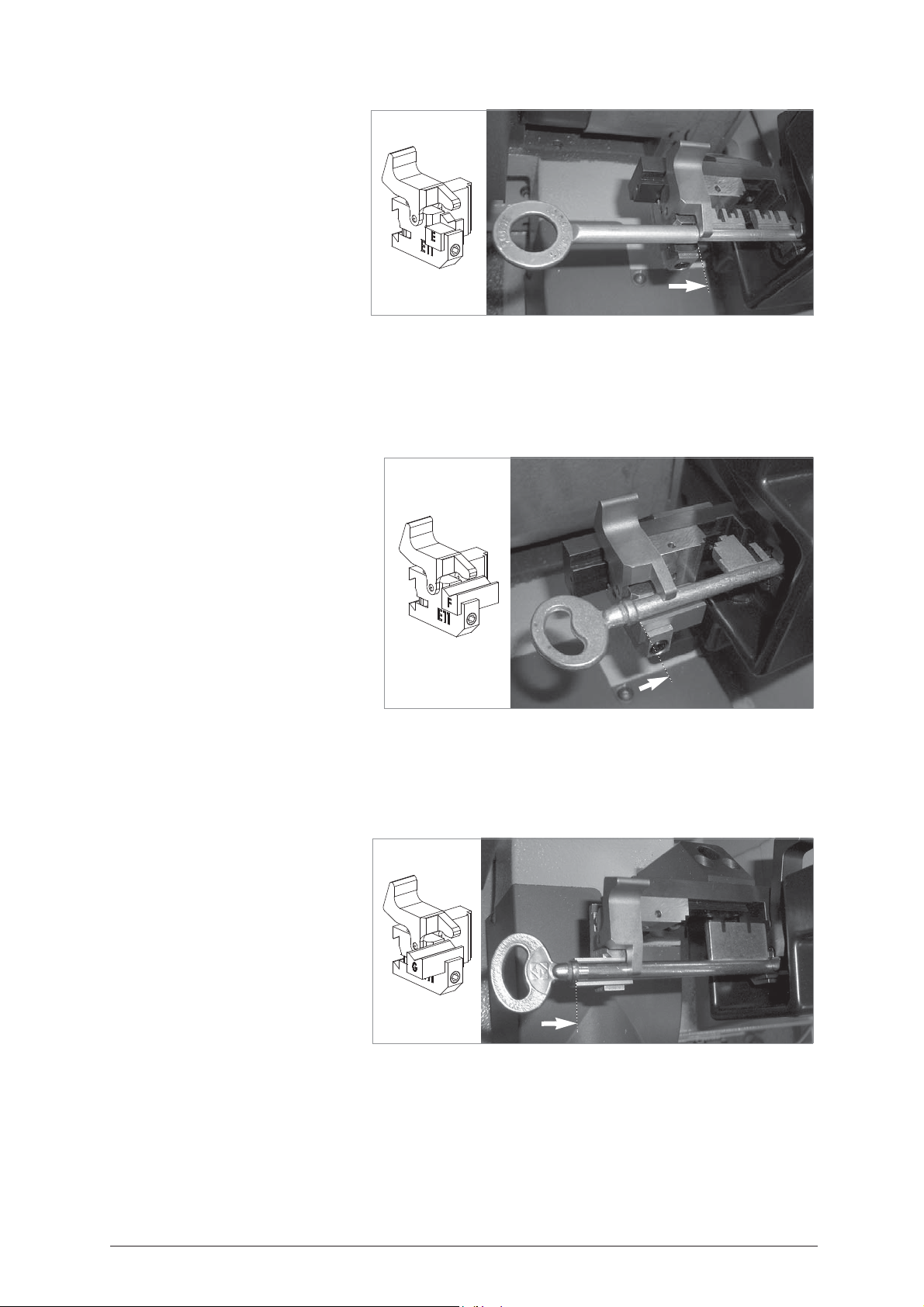
IDEA Operating Manual - English
Jaws A - E
READING / DECODING [SSN110]
1) Remove the mobile unit B from the
S100 clamp.
2) Fit the E11 mobile adapter on the S100
clamp.
3) Fit the jaw E (with the letter facing the
operator) into the E11 adapter.
4) Open the fixed clamp (A) and mobile
clamp (E) by pressing on the gripper
lever.
5) Place the key into its seat and take the
bit up against the fixed clamp (A).
Fig. 62
ATTENTION: position the key so that the first tooth is facing to the left, ensuring contact with the stop (0) on the
vertical face of the tooth (fig. 62).
6) Release the gripper lever.
ATTENTION: the rear stop must butt against the face of jaw E (fig. 62).
7) On starting the reading operation the carriage will take the key into contact with the laser beam along the path dictated
by the software.
8) In the case of female keys, use one of the standard centring devices (according to stem diameter) on the S100-A
clamp (see ch.5.14 "SPECIAL BIT FEMALE KEYS", page 57).
Jaws A - F
READING
1) Remove the mobile unit B from the S100
clamp.
2) Fit the E11 mobile adapter on the S100
clamp.
3) Fit the jaw F (with the letter towards the
operator) on the E11 adapter.
4) Open the fixed clamp (A) and mobile
clamp (F) by pressing on the gripper
lever.
5) Fit the key into its seat and take the bit up
against the fixed clamp (A).
ATTENTION: position the key so that the
first tooth is facing to the left, ensuring
contact with the stop (0) on the vertical face
of the tooth (fig. 63).
6) Release the gripper lever.
ATTENTION: the rear stop must butt against the face of jaw F (fig. 63).
7) On starting the reading operation the carriage will take the key into contact with the laser beam along the path dictated
by the software.
8) In the case of female keys, use one of the standard centring devices (according to stem diameter) on the S100-A
clamp (see ch. 5.14 "SPECIAL BIT FEMALE KEYS", page 57).
Fig. 63
Jaws A - G
READING
1) Remove the mobile unit B from the
S100 clamp.
2) Fit the E11 mobile adapter on the S100
clamp.
3) Fit jaw G (with the letter towards the
operator) into the E11 adapter.
4) Open the fixed clamp (A) and the
mobile clamp (G) by pressing on the
gripper lever.
5) Fit the key into its seat and take the bit
up against the fixed clamp (A).
ATTENTION: position the key so that the first tooth is facing left, ensuring contact with the stop (0) on the vertical
face of the tooth (fig. 64).
6) Release the gripper lever.
ATTENTION: the rear stop must butt against the face of jaw G (fig. 64).
7) On starting the reading operation the carriage will take the key into contact with the laser beam along the path dictated
by the software.
8) In the case of female keys, use one of the standard centring devices (according to stem diameter) on the S100-A
clamp (see ch. 5.14 "SPECIAL BIT FEMALE KEYS", page 57).
46 Copyright Silca 2004
Fig. 64
Page 51
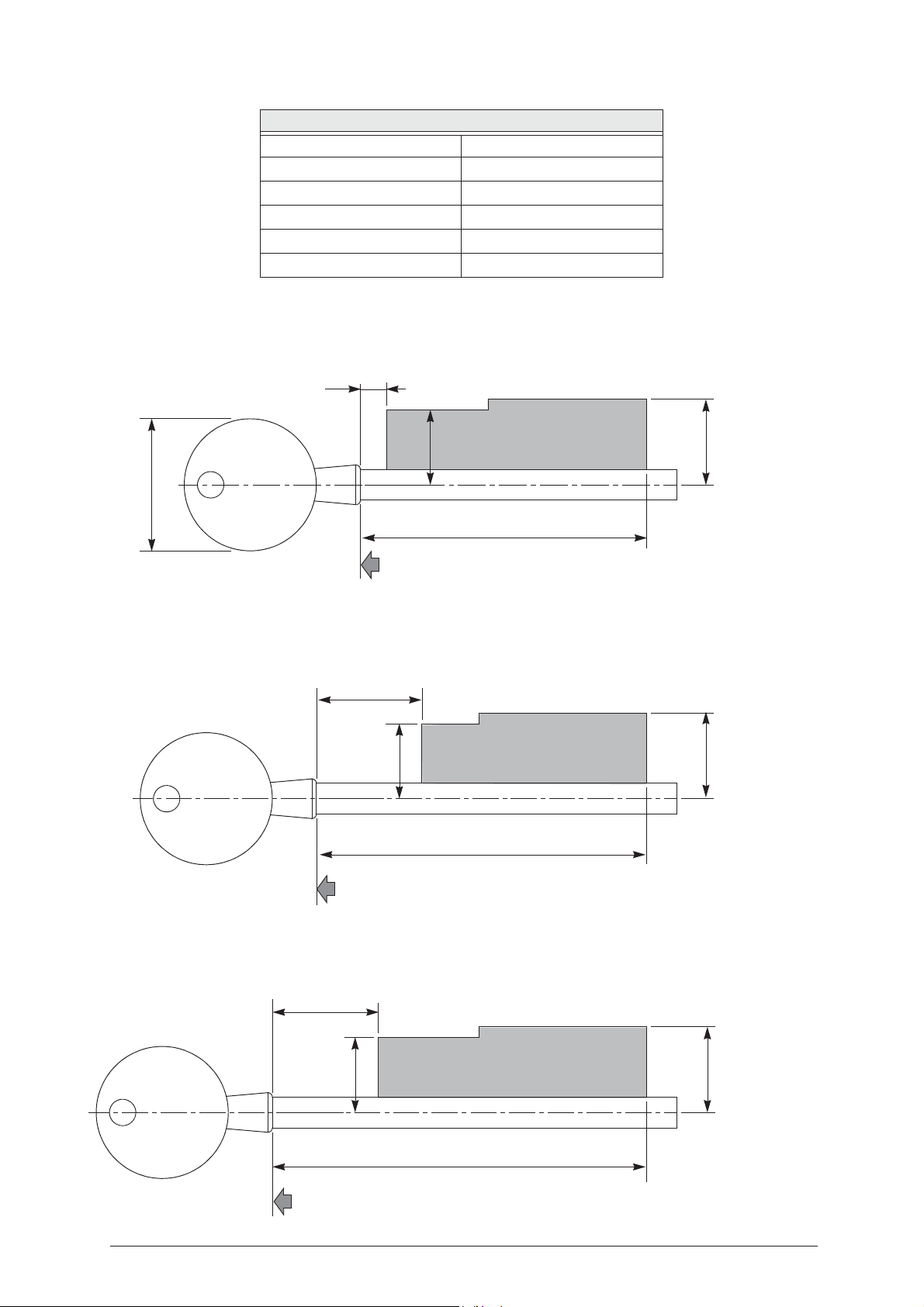
Operating Manual - English IDEA
Adapter
G
24
Max. 85
19.5
17
Jaws A - G
(example: Silca key ref. 6M24)
Rear Stop
Adapter
F
Adapter
E
Max. 75
Max. 65
19.5 19.5
24
17
17
6
Max. 30
Jaws A - F
Jaws A - E
(example: Silca key ref. 6M14)
(example: Silca key ref. 6FT12)
Rear Stop
Rear Stop
TYPE OF KEYS
Stem diameter min. 5 mm - max. 7 mm
Collar diameter max. 9 mm
Bit length in reading max. 40 mm
Bit height max. 17 mm / 19,5 mm
Distance from stop to bit min. 6 mm
Head width max. 30 mm
Choosing an adapter for READING
Place the original key on the drawing, using the Rear Stop as a reference; the bit should enter the highlighted zone.
Copyright Silca 2004 47
Page 52
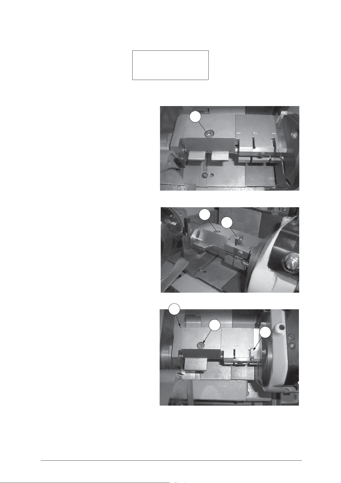
IDEA Operating Manual - English
CUTTING
Left blank Brass
Clamp: S1-K2 Stop: ?
Cutt.: 1.25
Pcs. = 1/1 [START]
ATTENTION: the “cutting STOP” is not presented automatically by the machine. The operator must identify it
CUTTING (Stop 1) / DECODING SSN 110
Remove the plate (P) in order to fit the key blank
into the rotating clamp (S1) from the front
the stem into the “V” on the jaws of the K2 tailstock.
Take care to keep the bit in the horizontal position
and the key stop up against the stop (STOP 1).
Secure the key by tightening the jaw screw (W2)
with the (T4) wrench (fig. 65).
Replace the (T4) wrench in its seat.
from the diagram on page 49 and enter it from the keyboard when the display requires it.
(*)
placing
Fig. 65
W2
CUTTING
Raise the positioning plate (P) and fit the key blank
into the rotating clamp (S1) from the front
placing the stem into the “V” on the jaws of the K2
tailstock. Take care to keep the bit in the horizontal
position and the key stop up against the stop
(STOP 2) achieved by fitting the plate (P) into its
seat and securing the key by tightening the jaw
screw (W2) with the (T4) wrench (fig. 66).
Replace the (T4) key in its seat.
CUTTING
Raise the positioning plate (P) e and fit the key
blank into the rotating clamp (S1) from the front
placing the stem into the “V” on the jaws of the K2
tailstock. Take care to keep the bit in the horizontal
position and the key stop up against the stop
(STOP 3) achieved by fitting the plate (P) into its
seat and securing the key by tightening the jaw
screw (W2) with the (T4) wrench (fig. 67).
Replace the (T4) wrench into its seat.
(Stop 2)
(*)
Fig. 66
(Stop 3)
(*)
W2
P
W1
W2
P
Fig. 67
(*) Important:the key can be fitted into the S1-K2 clamp from the front or from the back, according to the
type of key.
48 Copyright Silca 2004
Page 53
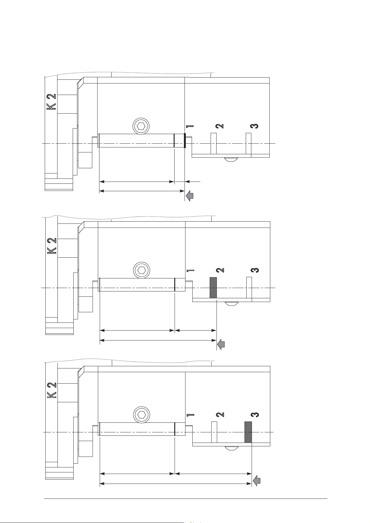
Operating Manual - English IDEA
43
49
6
43 24
67
43 44
87
Stop 1
(example: Silca key ref. 6FT12)
Stop 2
(example: Silca key ref. 6M14)
Stop 3
(example: Silca key ref. 6M24)
Stop
Stop
Stop
Choosing a STOP for CUTTING
1) place the original key on the drawing, using the stop as a reference.
2) in this position the bit should enter the 43 mm zone.
Copyright Silca 2004 49
Page 54
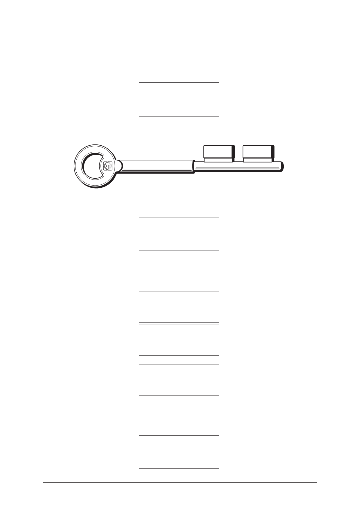
IDEA Operating Manual - English
Cutting in progress
Copy: 1 of: 1
Copy 1 of 1
finished
More copies ?
No=STOP Yes=ENTER
DECODE SSN 110
Art. Silca 6FT12
ATTENTION: for Fichet Sans-Soucis P.P. keys operations only possible when decoding with SSN 110.
Decoding + Cutting
SSN 110 (Decode)
Make =
=> Fichet
Sans-Soucis P. P.
Decode SSN: 110
Original on right
Clamp S100 A-E Stop 0
Adapt. E11 [START]
Press START,
Decoding
in progress…
Bit 1
*0790636***6360970*
Possible depths
0123456789# [8]
Press ENTER,
SSN: 110 M1 Brass
Clamp S1 – K2 Stop 1
Cutter: 1,25
Pcs. 1 / 1 [START]
Press START to cut.
Cutting in progress
Copy: 1 of: 1
Copy 1 of 1
finished
More copies ?
No=STOP Yes=ENTER
50 Copyright Silca 2004
Page 55
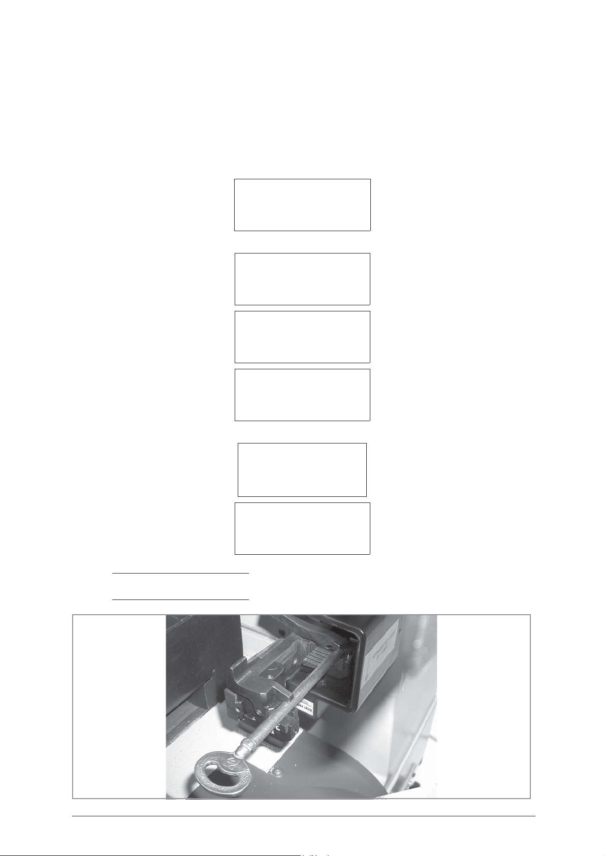
Operating Manual - English IDEA
5.12.1 FRENCH REAR STOP KEYS
For this type of keys see the information in Chapter
Female keys)", page 43.
TYPES OF KEYS: see page 47.
OPERATION FLOW
Choose
Choose
option 0 - Copy from Original
0 - Copy from Original
1 - Decode and Copy
2 - Insert cuts
3 - Queue from PC >>
option 8 - Rear Stop french
SELECT TYPE OF KEY
0 - Bit stop male
1 - Bit stop female
2 - Shoulder stop
3 - Pump
4 - Square-square tip
5 - Square-round tip
6 - Square stepped tip
5.12 "KEYS WITH REAR STOP (Male keys and
7 - Rear stop
8 - Rear stop french
9 - Small bit
10 - Special bit female
Choose
option 1
–
Reading + Cutting
1 - Reading + Cutting
2 - Cutting only
3 - Reading only
4 - Post-Reading adj.
KEY READING
Original on right
Clamp.: S100 A-E Stop: 0
Adapt.: E11 [START]
NOTE: Jaws F or G could also be used (see JAWS A-E / A-F / A-G on page 46. The rear stop is not
necessarily up against the side of the jaw (fig. 68).
Fig. 68
Copyright Silca 2004 51
Page 56
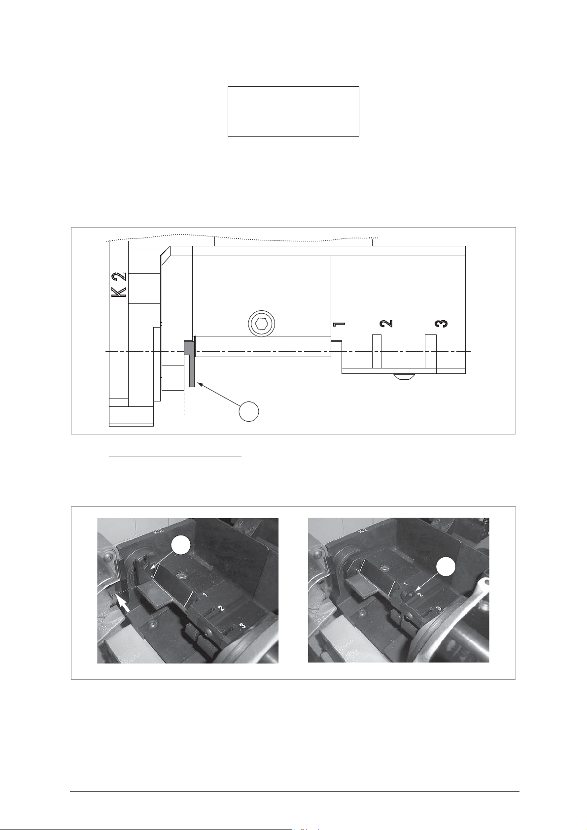
IDEA Operating Manual - English
CUTTING
Left blank Brass
Clamp: S1-K2 Stop: 0
Cutt.: 1.25
Pcsz. = 1/1 [START]
• CUTTING (Stop 0)
Raise the positioning plate (P) and fit the key blank into the rotating clamp (S1) from the front end (*). Place
the stem into the ‘V’ on the jaws of the K2 tailstock, taking care to keep the bit horizontal and the key stop up
against the stop (STOP 0) obtained by fitting the plate (P) up against the front end of the K2 tailstock.
Secure the key by tightening the jaw screw (W2) with the wrench (T4) (fig. 67).
Replace the plate (P) in position in seat 2 or 3.
Replace the (T4) wrench in its seat.
Fig. 69
Fig. 70
P
Stop 0
0
NOTE: the key can be fitted into the S1-K2 clamp from the front or from the back, according to the
type of key
P
P
52 Copyright Silca 2004
Page 57
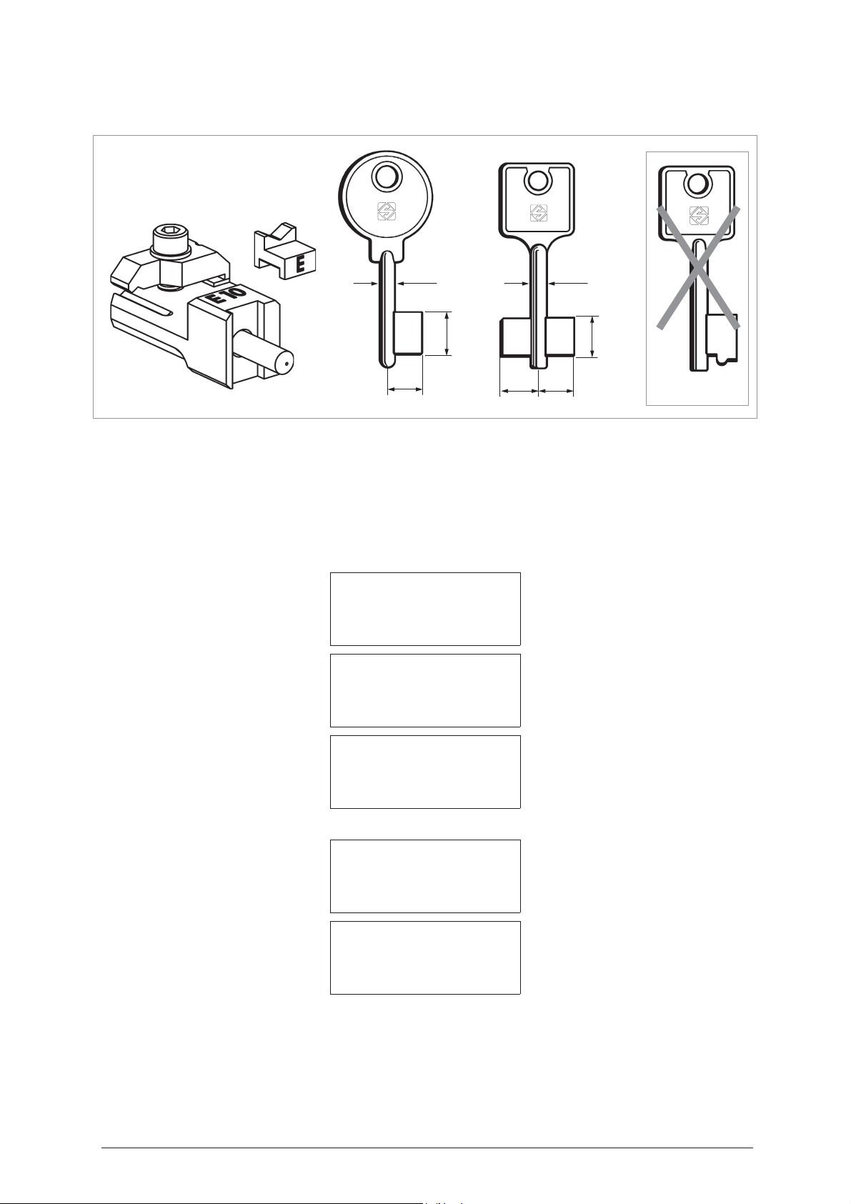
Operating Manual - English IDEA
NO!
D727711ZB
Adapters
OPTIONAL
5.13 SMALL BIT / DOUBLE BIT KEYS
max 4
max 18
max 12
Fig. 71
The set comprises
E10
Adapter for small bit or double bit keys (E10 = ID initials), used for cutting.
E
Adapter for small bit or double bit keys (E = ID initials), used for reading (to fit to the S100 clamp in the place
:
max 12
max 4
max 18
max 12
of jaw B).
When the machine requires (indicates on display) adapter
- It is very important to distinguish the type of key to be copied: Choose
SELECT TYPE OF KEY
0 - Bit stop male
1 - Bit stop female
2 - Shoulder stop
3 - Pump
4 - Square-square tip
5 - Square-round tip
6 - Square stepped tip
E10
or E, proceed as follows:
option 9 - Small bit
.
Choose
option 1
Operate as follows
-
Reading + Copying
:
7 - Rear stop
8 - Rear stop french
9 - Small bit
10 - Special bit female
:
1 - Reading + Copying
2 - Cutting only
3 - Reading only
4 - Post-Reading adj.
KEY READING
Original on right
Clamp: S100 A - E Stop: 0
[START]
Copyright Silca 2004 53
Page 58
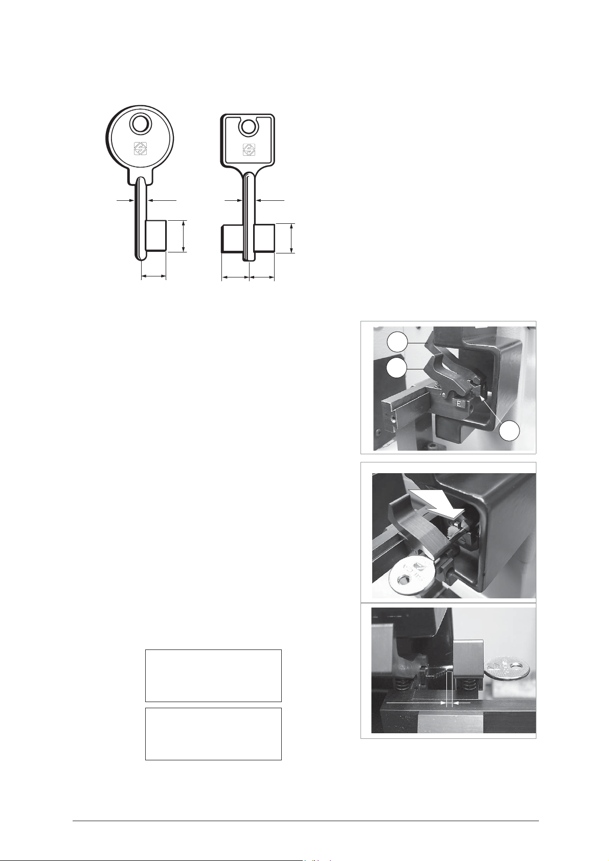
IDEA Operating Manual - English
Note:
Maximum dimensions of keys for Reading from
the original:
- Max. stem thickness = 4 mm
- Max bit length = 18 mm
- Max. bit height = 12 mm
If these conditions are not observed, the
machine will produce the error “Key cannot be
decoded”.
READING small bit or small double bit keys
Fig. 72
max 4
max 12
max 18
max 12
max 4
max 18
max 12
1) Press the grip on the S100 mobile clamp and remove the adapter (jaw
B).
2) Install jaw
E
so that the letter E is facing the operator.
3) Open the fixed clamp (A) and the mobile clamp (E) by exerting
pressure on the jaw lever (F) and (F1) (fig. 73).
Fig. 73
4) Fit the key into the special seat (axis X1) taking the bit all the way into
the fixed clamp (A) (fig. 74).
ATTENTION: position the key so that the highest tooth is facing left,
ensuring contact with the stop (0) on the vertical side
of the tooth.
5) Release the jaw lever.
6) Place the mobile clamp (E) in the best position on the stem between
the bit and key head. Make sure that there is a distance of min. 3 mm
and max. 15 mm between the bit and inside of the mobile clamp (E)
(fig. 87).
When the reading process starts the carriage will take the key into contact
with the laser beam along the path dictated by the Software.
Fig. 74
F
F1
A
7) At the end of the cycle see the message on the display in order to
continue.
Fig. 75
Reading in progress…
Data processing
in progress
Please wait…
54 Copyright Silca 2004
min. 3 mm
max. 15 mm
Page 59
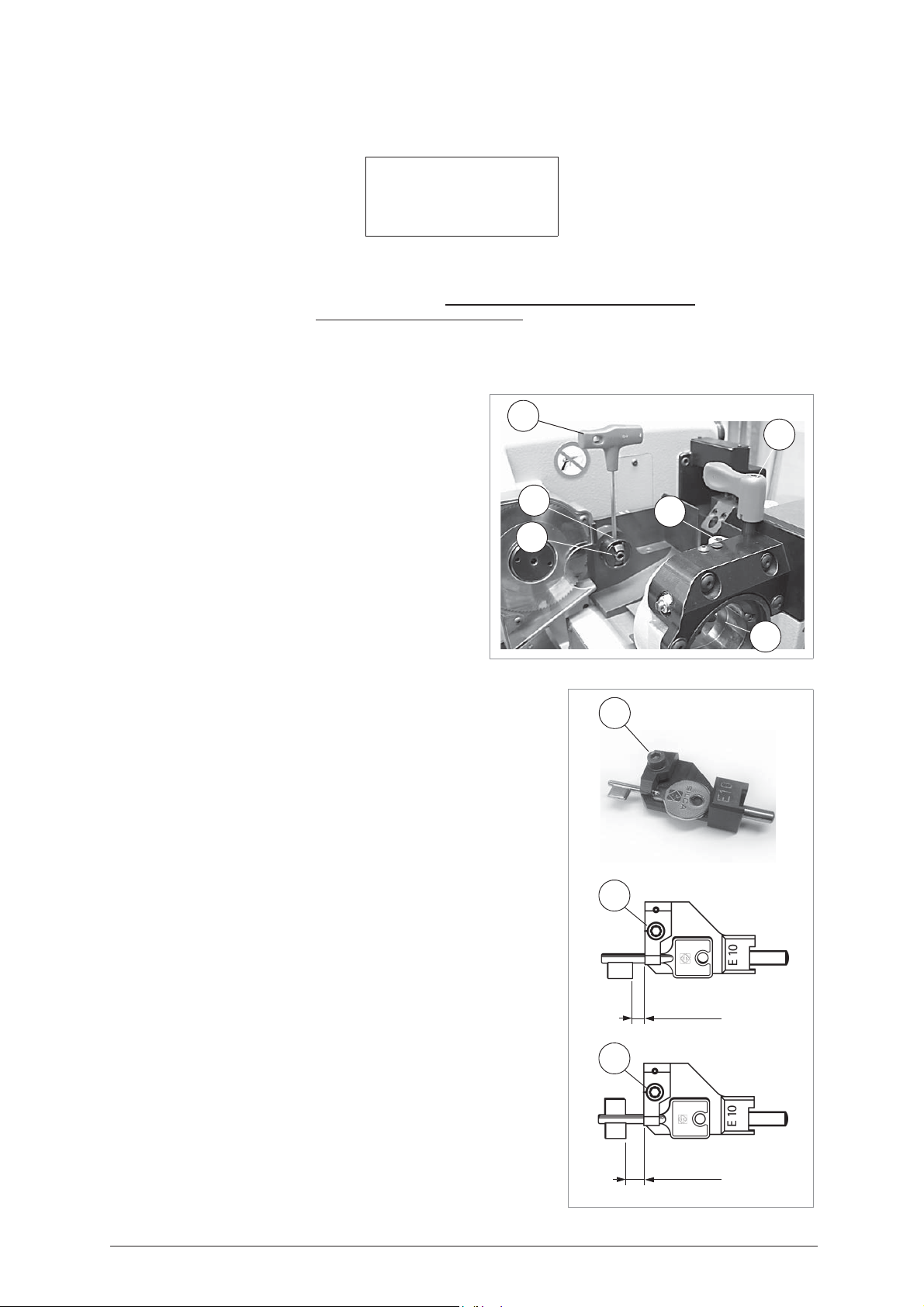
Operating Manual - English IDEA
V2
T1
S1
K1
T4
V1
CUTTING small bit or small double bit keys
Left blank Brass
Clamp: S1-K1 Stop: 0
Cutt : 1.25 Adapt.: E10
Pcs. = 1/1 [START]
Clamp: S1- K1 =
Stop 0 =
Cutter: 1.25 =
Brass/Steel =
Adapter E10
ATTENTION: always check that the wording corresponds to the material of the key.
The key blank to be cut must be positioned according to the
parameters given on the display after selecting the program
involved; the type of key (small bits) with front stop requires the
use of adapter
Please follow the instructions below carefully, and observe the
order of operations.
1) Loosen the knob (T1) by turning it anticlockwise until the
2) Orient the standard tailstock (K1) for male keys in the
3) Take the ‘T’ wrench (T4) from its seat and fit into the screw (V1) (fig. 76),
reference or positioning point on the key cutting clamp.
rotating clamp (S1) can be moved to a convenient distance
for fitting the key).
special seat on the support, using the screw (V2) to direct it
upwards (fig. 76).
then loosen until the jaws are fully open. At the end of the operation do
not remove the ‘T’ wrench from the screw (V1).
indicates which clamp (S1) and tailstock (K1) to use for gripping the key.
thickness of the cutter currently selected (press SHIFT+ENTER to change thickness).
material of the key (press SHIFT+ ? to change material).
= shows the adapter to fit on the rotating clamp in order to position the key properly.
E10
and the key reference on “Stop 0”.
Fig. 76
P
4) Fit the key blank into the adapter E10, taking care to position it properly
(fig. 77); tighten the (P) screw.
ATTENTION:
For single bit keys the distance between the adapter and the end of the bit
should be at least 2-3 mm (fig. 77). For double bit keys the distance between
the adapter and the end of the bit should be at least 8 mm (fig. 77). If these
measurements are not observed the display will show an error: “ERROR 17
Adapter not properly fitted”.
Fig. 77
P
min. 3mm
P
min. 8mm
Copyright Silca 2004 55
Page 60
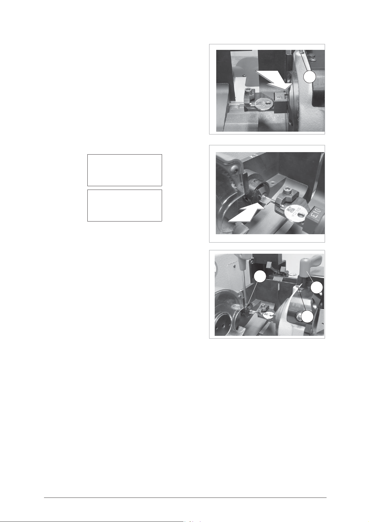
IDEA Operating Manual - English
V1
V2
T1
5) Fit the E10 adapter, with the key blank in the rotating clamp (S1)
from the inside, take the adapter up to the side of the self-centring
jaws (fig. 78) and slightly close the grips on the rotating clamp with
the ’T’ wrench (T4).
6) Move the rotating clamp (S1) so that the key fits into the tailstock
(K1) with the bit all the way in (fig. 79).
7) Tighten the knob (T1). Use the T wrench (T4) to tighten the screw
(V1) first, then the screw (V2) (fig. 80). Replace the ‘T’ wrench
(T4) into its seat, lower the mobile safety shield and begin the
process with START.
Fig. 78
Cutting in progress…
Copy: 1 of: 1
Copy 1 of 1
finished
More copies ?
No=STOP Yes=ENTER
To make further copies of the key, you can now press ENTER.
Fig. 79
V1
Fig. 80
56 Copyright Silca 2004
Page 61
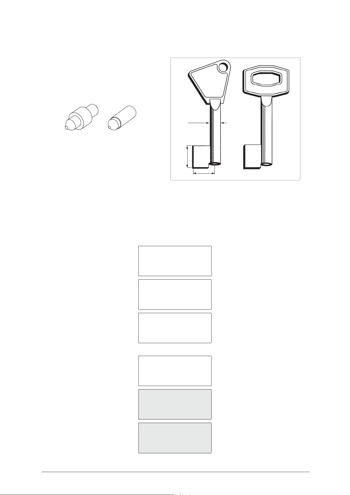
Operating Manual - English IDEA
5.14 SPECIAL BIT FEMALE KEYS
OPTIONAL
D728717ZB
Adapters
max 7 mm
E15 E16
max 31 mm
max 15 mm
Fig. 81
The set comprises
E15
Adapter – Centring device (E15 = ID code), used for cutting (install on the K1 tailstock).
E16
Adapter – Centring device (E16 = ID code), used for reading (install on the S100 - A clamp).
When the machine requires (indicates on display) adapter
:
E15
or
E16
, proceed as follows:
- It is very important to distinguish the type of key to be copied:
- Choose
option 10 - Special Bit Female
.
SELECT TYPE OF KEY
0 - Bit stop male
1 - Bit stop female
2 - Shoulder stop
3 - Pump
4 - Square-square tip
5 - Square-round tip
6 - Square stepped tip
7 - Rear stop
8 - Rear stop french
9 - Small bit
10 - Special bit female
Choose
option 1
– Reading + Copying:
1 - Reading + Copying
2 - Cutting only
3 - Reading only
4 - Post-Reading adj.
KEY READING
Original on right
Clamp: S100 A - B Stop:0
Adapt. E16 [START]
Is adaptor E16
installed ?
No=STOP Yes=START
Copyright Silca 2004 57
Page 62
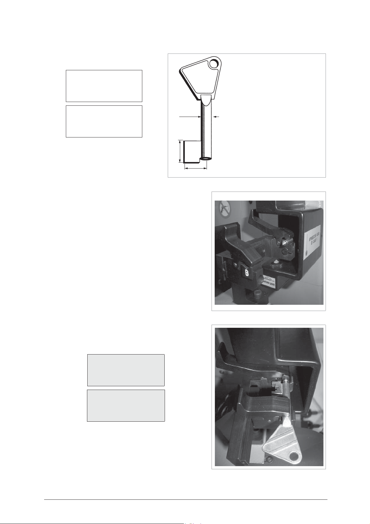
IDEA Operating Manual - English
max 15 mm
max 31 mm
max 7 mm
Note:
Maximum dimensions of keys for
Reading from the original:
- Max. stem thickness = 7 mm
- Max bit length = 31 mm
- Max. bit height = 15 mm
If these conditions are not observed,
the machine will produce the error
“Key cannot be decoded”.
Reading
KEY READING
Original on right
Clamp: S100 A - B Stop:0
Adapt. E16 [START]
Is adaptor E16
installed ?
No=STOP Yes=START
1) Press on the grip lever of the fixed clamp (A) and fit the centring
device E16 so that it protrudes towards the mobile clamp (B) (fig.
82). Release the grip lever.
2) Press on the grip lever on the mobile clamp (B) and fit the key so
that the hole in the stem is up against the centring device E16 (fig.
83). Release the grip lever.
3) Hold the key head with one hand and the end of the centring
device with the other and push the key up against the stop 0 (A).
4) The ideal position for the mobile clamp (B) is when there is a
distance of 3 mm min. and 15 mm max. between the bit and inner
side of the mobile clamp (B).
Clamp: S100 A-B
= indicates the clamp
(S100)
into which the key
must be fitted, and which jaw to use.
Stop 0
= reference or point for positioning the key on the reading
clamp.
Adapt: E16
= adapter for positioning the key (female) from the tip
(only for reading).
ATTENTION: make sure that the bit is up against the Stop 0 (A).
Fig. 82
Pressing Start shows:
Left blank Brass
Clamp: S1-K1 Stop:0
Cutt: 1.25 Adptt: E15
pcs. = 1/1 [START]
Is adaptor E15
installed ?
No=STOP Yes=START
Fig. 83
58 Copyright Silca 2004
Page 63
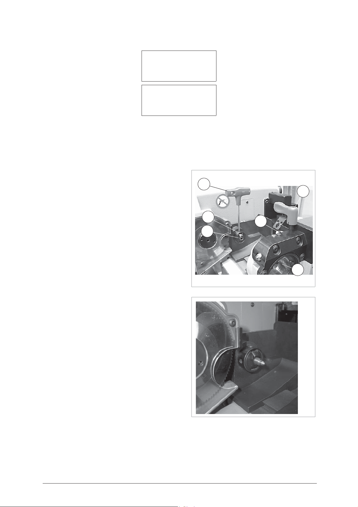
Operating Manual - English IDEA
V2
T1
S1
K1
T4
V1
Cutting
Left blank Brass
Clamp: S1-K1 Stop: 0
Cutt: 1.25 Adapt: E16
Pcs. = 1/1 [START]
Is adaptor E15
installed ?
No=STOP Yes=START
Clamp: S1- K1
Stop 0
= reference or point for positioning the key on the cutting clamp.
Cutter: 1.25
Brass/Steel
Adapter E15
ATTENTION: always check that the wording corresponds to the material of the key.
The key blank to be cut must be positioned according to the
parameters given on the display after selecting the program
involved
rotating clamp
key reference on
Please follow the instructions below carefully, and observe the
order of operations
1) Loosen the knob (T1) by turning it anticlockwise until the
rotating clamp (S1) can be moved to a convenient distance
for fitting the key.
2) Fit the adapter E15 into the tailstock K1 up against the
mechanical stop (fig. 85).
3) Use the T wrench (T4) to tighten the screw (V2) on the
tailstock and secure the E15 adapter.
E15 must be properly fitted into its seat and pressed up
against the stop point.
= indicates which clamp (S1) and tailstock (K1) to use for gripping the key.
= thickness of the currently selected cutter (press SHIFT+ENTER to change thickness).
= material of the key (press SHIFT+ ? to change material).
= adapter (centring device) to position the tip of the key (female) properly. Fit into the K1 tailstock.
;
the type of key with front stop requires the use of the
(S1),
the ‘K1’ tailstock, the
“Stop 0”.
.
E15
adapter and the
Attention:
the adapter
Fig. 84
4) Take the T wrench (T4) from its seat and open the rotating
clamp jaws by turning the sunk hex. screw (V1); at the end
of the operation leave the T wrench in the screw (V1).
5) Fit the key blank into the front side of the rotating clamp (S1)
and position it on the groove in the jaws, then take the key
forward until the adapter E15 goes into the hole in the stem
(fig. 86).
Fig. 85
Copyright Silca 2004 59
Page 64

IDEA Operating Manual - English
6) Close the mobile clamp jaws slightly, using the T wrench
(T4) already in the screw (V1), without gripping the key stem;
move the rotating clamp (S1) towards the tailstock until the
adapter E15 goes into the hole in the stem keeping a
minimum safety distance of 10 mm between the rotating
V1
clamp jaws and the rear limit of the bit. Secure the rotating
clamp in position by means of knob (T1).
7) Hold the key head in the left hand and align crosswise
making sure that the bit is all the way up against the adapter
E15 on the tailstock (K1), then close the grips round the key
stem, using the T wrench (T4) already in place on the screw
(V1).
8) Replace the T wrench (T4) in its seat, lower the mobile safety
shield and begin the process with START.
To remove the
key after cutting, carry out the operations described, in
reverse order
.
Fig. 86
- Pressing Start shows:
Reading in progress…
- When the reading process starts the carriage will take the key into contact with the laser beam along the path dictated
by the Software, at the end of the cycle see the message on the display in order to continue.
Data processing
in progress
Please wait…
Cutting in progress…
Copy: 1 of: 1
Copy 1 of 1
finished
More copies ?
No=STOP Yes=ENTER
To make further copies of the key, you can now press ENTER.
60 Copyright Silca 2004
Page 65
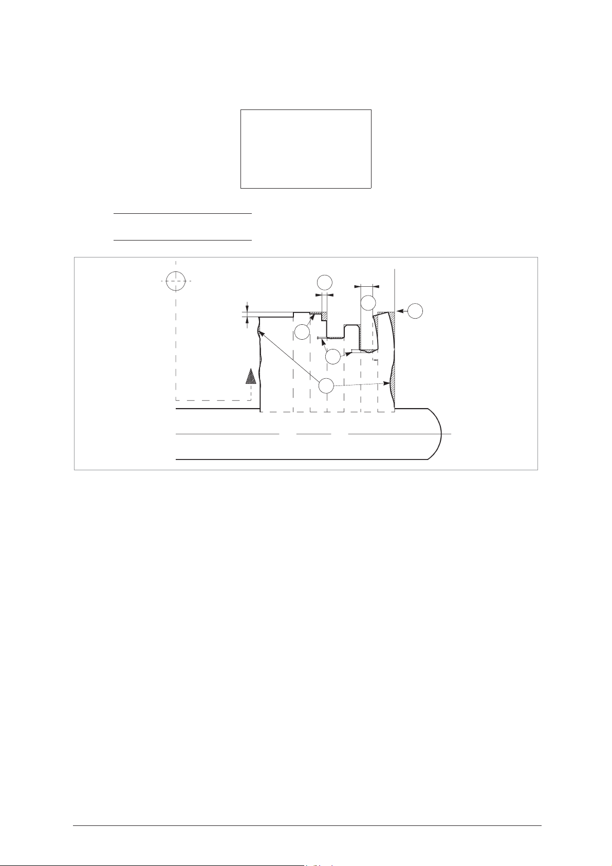
Operating Manual - English IDEA
5.15 POST-READING
To correct any defects found on the original key, proceed as follows:
Use the arrows [Up/Down] to scroll.
NOTE: an asterisk (*) next to one or more of the choices listed indicates that the relative adjustment
has been made.
LASER
ADJUSTMENTS TO MAKE TO THE KEY AFTER READING
ADJ. POST-READING
0 - Delete adjustments
1 - Front-Rear conv.
2 - X s p e c u l a r c o n v .
3 - Cut depth correction
4 - Bit correction
min.
0.3 mm
A
B
min.
0,3 mm
F
D
C
Fig. 87
E
1) Bent teeth are re-aligned vertically over the projection of the support base. The minimum distance
between the edges must be at least 0.3 mm.
2) Worn edges on the top part of positive teeth are squared over the projection of the maximum width and
height read from the tooth.
3) If the base of negative teeth is worn, depth is corrected up to the highest measurement for the side edges
(less worn as leverage is normally exercised on the centre).
4) Steps read on very wide parts of the bit (cutting close to the lock tooth, identical adjacent cuts, etc.) are
aligned on the highest measurement if the difference is no more than 0.15 mm.
5) Scratches, wear or warping read on both the vertical and horizontal faces of the teeth are regulated over
the size of the tooth at its base on the stem.
6) Steps with a thickness of less than 0.75 mm are regulated over the prevailing measurement of the
adjacent tooth.
Copyright Silca 2004 61
Page 66
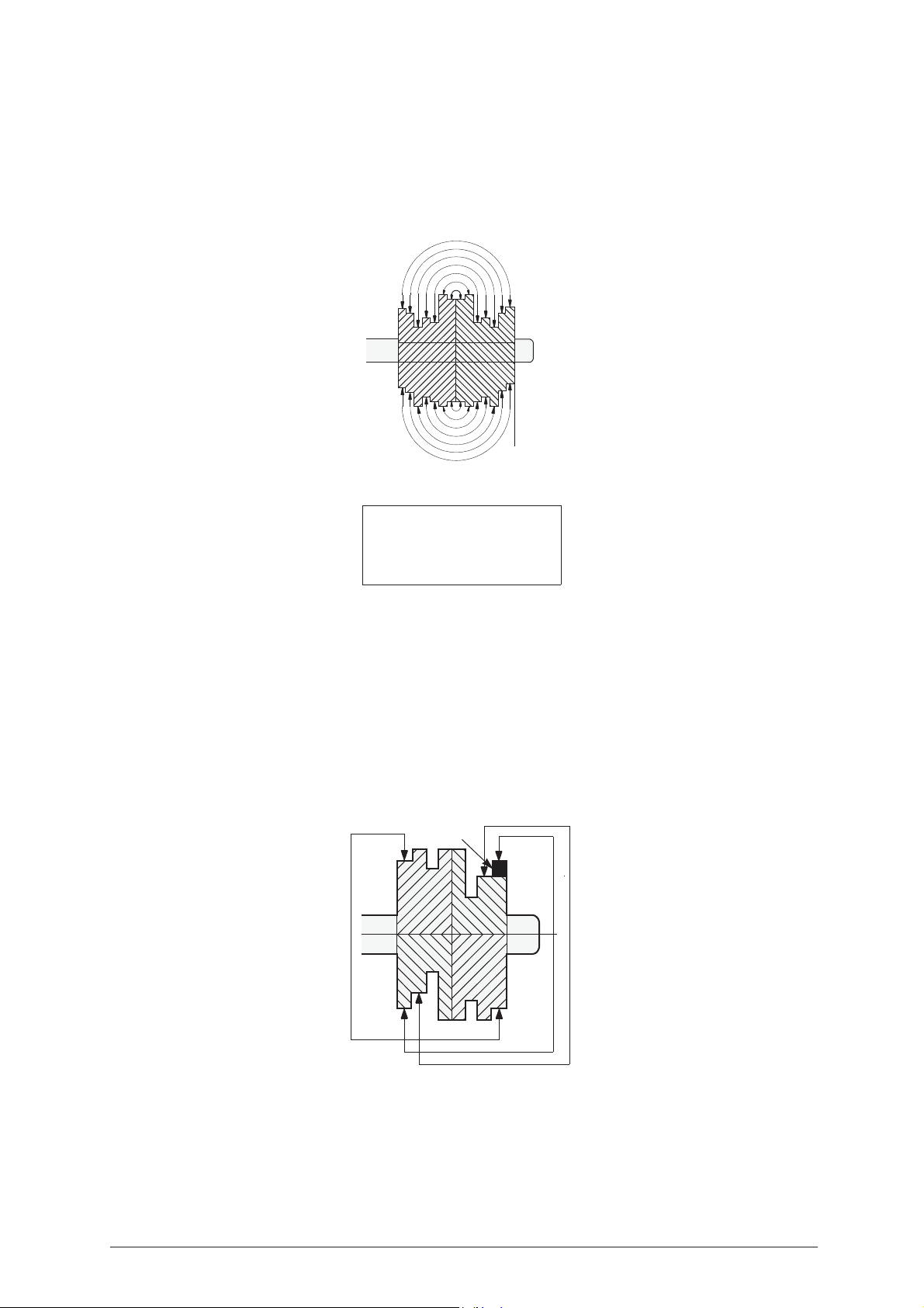
IDEA Operating Manual - English
5.15.1 Front-rear bit conversion
The "FRONT-REAR BIT CONVERSION" function makes it possible to make a supplementary correction to
the data read from a key which has symmetrical cuts on the bit. The operator may activate this function when
part of the bit is more worn than its corresponding part (e.g. wear on the side of the key which operates only
on the outside of the lock) or a tooth is missing or broken which was identical to the one symmetrically placed
on the opposite side of the bit (fig. 88).
REAR
Fig. 88
No=STOP Yes=ENTER
The software program which converts the bit divides it symmetrically into two parts (front and rear),
attributing each tooth with the deepest cut of the two teeth symmetrically opposed.
Stop
: to quit
Enter
: to continue (confirmation)
5.15.2 “X” Specular bit conversion
The “X SPECULAR BIT CONVERSION” function makes it possible to make a supplementary correction to
the data read from a key which has diagonally symmetrical cuts on the bit.
The operator may activate this function when part of the bit is more worn than its corresponding part (e.g.
wear on the side of the key which operates only on the outside of the lock) or a tooth is broken or missing
which was identical to the one specularly placed on the opposite side of the bit (fig. 89).
.
FRONT
Stop 0
Applicate
Front Rear
bit conversion ?
missing
tooth
Fig. 89
62 Copyright Silca 2004
Page 67
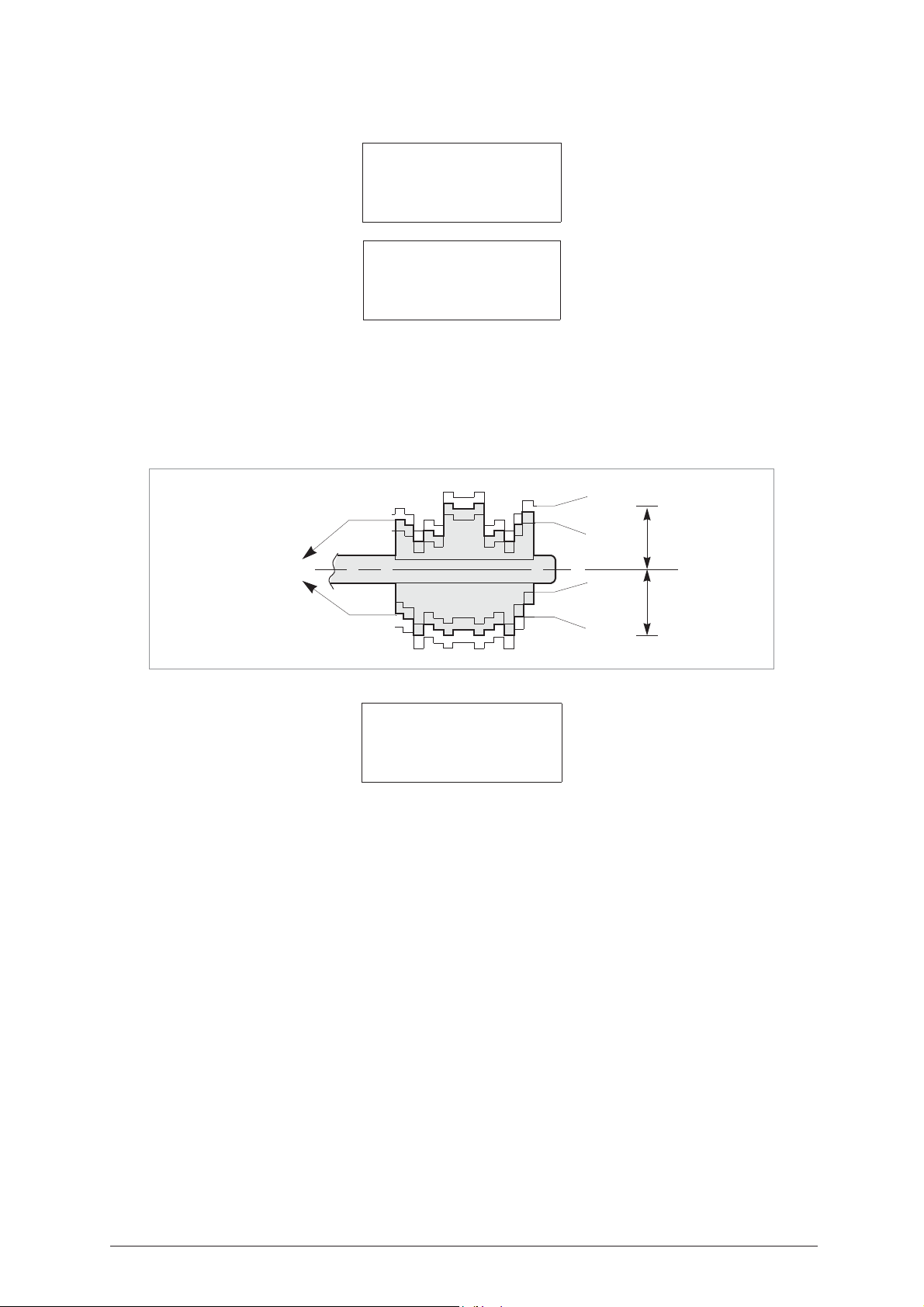
Operating Manual - English IDEA
Applicate
X specular
bit conversion ?
No=STOP Yes=ENTER
Bit Depth
Bit 1 = +00
Bit 2 = +00
[ENTER]=CONFIRM
Stop
: to quit
Enter
: to continue (confirmation)
5.15.3 Correcting bit depth
With the "CORRECTING BIT DEPTH" function a number of alterations can be made to measurements for
the cuts on all the teeth (on sides 1 and 2 for double bit keys) within the limits of min. -0.50 mm and max.
+0.50 mm
(+)
Fig. 90
MEASUREMENT
READ
Use SHIFT +
Use SHIFT +
[arrow Up] key for higher values (bit is cut less)
[arrow Down] key for lower values (bit is cut more)
Correcting Bit Depth
Bit 1 = +00
Bit 2 = +00
[ENTER] = CONFIRM
(-)
(-)
(+)
1st BIT
2nd BIT
Copyright Silca 2004 63
Page 68
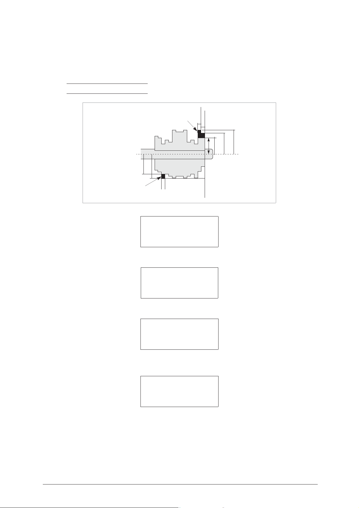
IDEA Operating Manual - English
1st side
2nd side
missing
tooth
missing
tooth
from 00.00
to 01.80
Stop 0
from 19.20
to 21.00
H 10.00
H 13.50
H 11.00
H 12.00
to 03.60
H 15.00
5.15.4 Bit construction
The "BIT CONSTRUCTION" function is useful when a positive tooth (the high part between two lows) has
broken off. As the program cannot formulate hypothetical compensation because it is not possible to read
the missing part of the bit, the operator must reconstruct the tooth involved, determining its position from the
front of the bit and establishing the measurements of the cuts (height from the stem axis).
It is possible to reconstruct up to a maximum of 6 teeth on each bit side (fig. 91).
NOTE: always calculate the position of the tooth from STOP 0.
Fig. 91
BIT CORRECTION
Select the bit:
1 - Bit 1
2 - Bit 2
Select BIT 1 for example.
Bit: 1 Tooth: 1
From: 0 to: 180
Height: 1200
Up Down
n p [ENTER}
Enter the position “from”, “to” and “height” of the tooth and press ENTER to confirm.
Bit: 1 Tooth: 2
From: 180 to: 360
Height: 1500
Up Down
n p
[ENTER}
Go on to the next tooth by pressing the [arrow Down].
Press STOP to quit.
Bit: 2 Tooth: 1
From: 1920 to: 2100
Height: 1350
Up Down
n p
[ENTER]
64 Copyright Silca 2004
Page 69
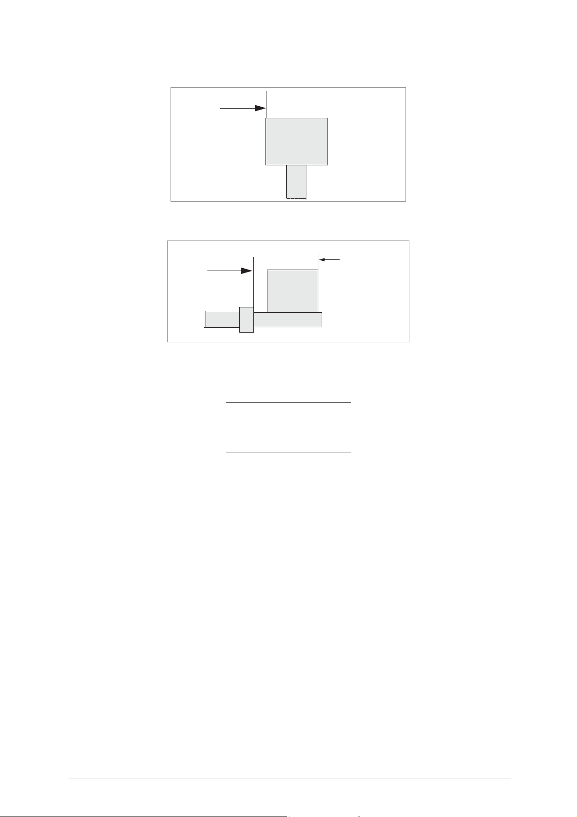
Operating Manual - English IDEA
Examples:
Pump keys
Stop 3
to calculate
tooth
construction
Fig. 92
Square stemmed keys:
Fig. 93
to calculate
tooth
construction
0 - D
ELETE EDITING
Stop 1
When a new key is read or the item “0-Delete editing” is selected, all the POST-READING adjustments
previously selected can be eliminated.
Delete
post-reading
adjustments ?
No=STOP Yes=ENTER
Stop
: to quit
Enter
: to continue (confirmation)
Copyright Silca 2004 65
Page 70

IDEA Operating Manual - English
5.16 D
Make a search for the SSN by entering the number corresponding to the system, and confirm with ENTER.
or by Make
• press the key [Right-hand arrow] to place the pointer next to the “Make” field.
It is enough to enter the first letters of the name; the name of the MAKE closest in alphabetical order
appears automatically
• the arrows can be used to scroll the sequence of previous and successive MAKES in alphabetical order.
• use the key [CLEAR] to delete the text entered.
• the last line of the window indicates the result of the search: “[04] List = ENTER”: 4 SSN have been
• the symbol >> indicates that there are other systems/locks
• press [arrow Down] to scroll the list and highlight the one required.
• To view further information relating to the SSN listed, hold down the key (Right-hand arrow).
After selecting the SSN, you will see:
ECODE AND COPY
SSN = 9 (Decode)
MFG =
=>CISA
CS_CSC
SSN = (Decode)
MFG = CISA
=>CISA
[04] List = ENTER
found, press [ENTER] to see the list.
CISA [04]
1: 5CS6P - 5CS8P
2: CS-CSC
3: CSL-CSLC-5CS1-5CS2 >>
DECODE SSN: 9
Original on right
Clamp: S100 A-B Stop:0
[START]
Clamp: S100 A-B
Stop: 0
Pressing START begins a quick process that reads only the cuts close to the teeth.
At the end a window appears showing the various cuts deduced from the depths read:
#.
123..
[arrow Down]= goes from one bit to the other
CLEAR
It is in any case possible to edit the symbols for the combination before proceeding with the cutting operation.
NOTE: see the next Chapter for the cutting sequence.
= reference or point for positioning the key in the reading clamp.
= a fixed tooth
= the symbol for the depth read
= delete symbols
= indicates the clamp (
Decoding in progress
Bit 1:2
123*456
Possible depths:
12345# [7]
S100
) into which the key must be fitted, and which jaws to use.
Bit: 1
66 Copyright Silca 2004
Page 71

Operating Manual - English IDEA
5.17 E
NTERING THE CUTS
Make a search for the SSN by entering the number corresponding to the system required, and confirm with
ENTER.
SSN = 9 (Cut)
MFG =
=>CISA
CS_CSC
or by Make
SSN = (Cut)
MFG = CISA
=>CISA
[03] List = ENTER
• press the key [Right-hand arrow] to place the pointer next to the “Make” field.
It is enough to enter the first letters of the name; the name of the MAKE closest in alphabetical order appears
automatically;
• the arrows can be used to scroll the sequence of previous and successive MAKES in alphabetical order.
• use the key [CLEAR] to delete the text entered.
• the last line of the window indicates the result of the search: “[04] List = ENTER”: 4 SSN have been
found, press [ENTER] to see the list.
CISA [04]
2: 5CS6P - 5CS8P
3: CS - CSC
4: CSL-CSLC-5CS1-5CS2
• the symbol >> indicates that there are other systems/locks
• press [Down arrow] to scroll the list and highlight the item required.
• to view further information relating to the SSN listed, hold down the key (Right-hand arrow).
After selecting the SSN, you will see:
Bit 1: 1 [ ------- ]
. . .? . . .
Possible depths:
12345# [7]
or in the case of a double bit:
Bit 1: 2 [ ------- ]
. . .? . . .
Possible depths:
12345# [7]
?
= indicates a fixed tooth and cannot be edited
123..
= the depth symbols admitted for the selected data card
SHIFT+?
[arrow Down]
CLEAR
[ ------- ] = ONLY from the box relating to BIT 1
characteristics of the key:
= produces the special character # that indicates a depth the same as that of the STEM.
= goes from one bit to the other
= deletes the symbols
with SHIFT + [arrow Up]to define one of the following
Copyright Silca 2004 67
Page 72
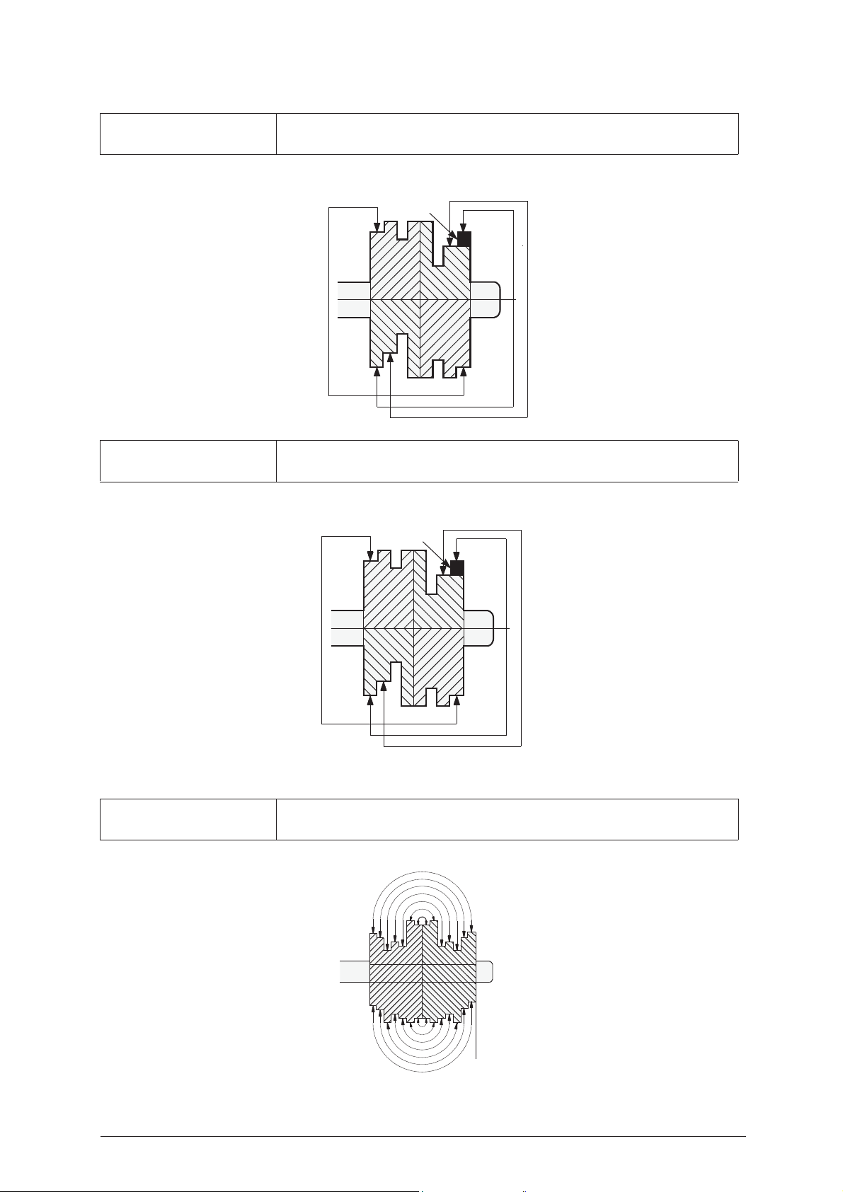
IDEA Operating Manual - English
missing
tooth
missing
tooth
Stop 0
REAR
FRONT
SYMMETRICAL
Bits 1 and 2 are the same: when the combination of bit 1 is entered, that for BIT 2 is
entered automatically.
Fig. 94
SPECULAR X Bits 1 and 2 are specular to X: when the combination of bit 1 is entered, that for BIT 2
is entered automatically.
Fig. 95
SPECULAR F-R Each bit is specular in the direction FRONT-BACK: enter half the cuts for each bit to
have the full combination.
Fig. 96
68 Copyright Silca 2004
Page 73

Operating Manual - English IDEA
After entering the cuts for all the bits, go on to cutting.
SSN: 9 M1 Brass
Clamp: S1-K1 Stop: 0
Cutter: 1.25
Pcs: 1/1 [START]
M1
= bit 1
Clamp: S1- K1
Stop 0
= reference or point for positioning the key in the cutting clamp.
Cutter: 1.25
Brass/Steel
Pc. 1/1
= enter the number of keys required.
= indicates which clamp (S1) and tailstock (K1) to use for gripping the key.
= thickness of the cutter currently selected (press SHIFT+ENTER to change thickness)
= material of the key (press SHIFT+ ? to change material)
ATTENTION: always check that the wording BRASS/STEEL corresponds to the material of the key
SHIFT+ENTER = used to change the thickness of the current cutter by pressing ENTER against the cutter
thickness required:
Choose cutter
1*: PL 1.25
2: PL 1.00
3: PL 1.50
Press STOP to quit.
Press START to begin cutting.
Copyright Silca 2004 69
Page 74
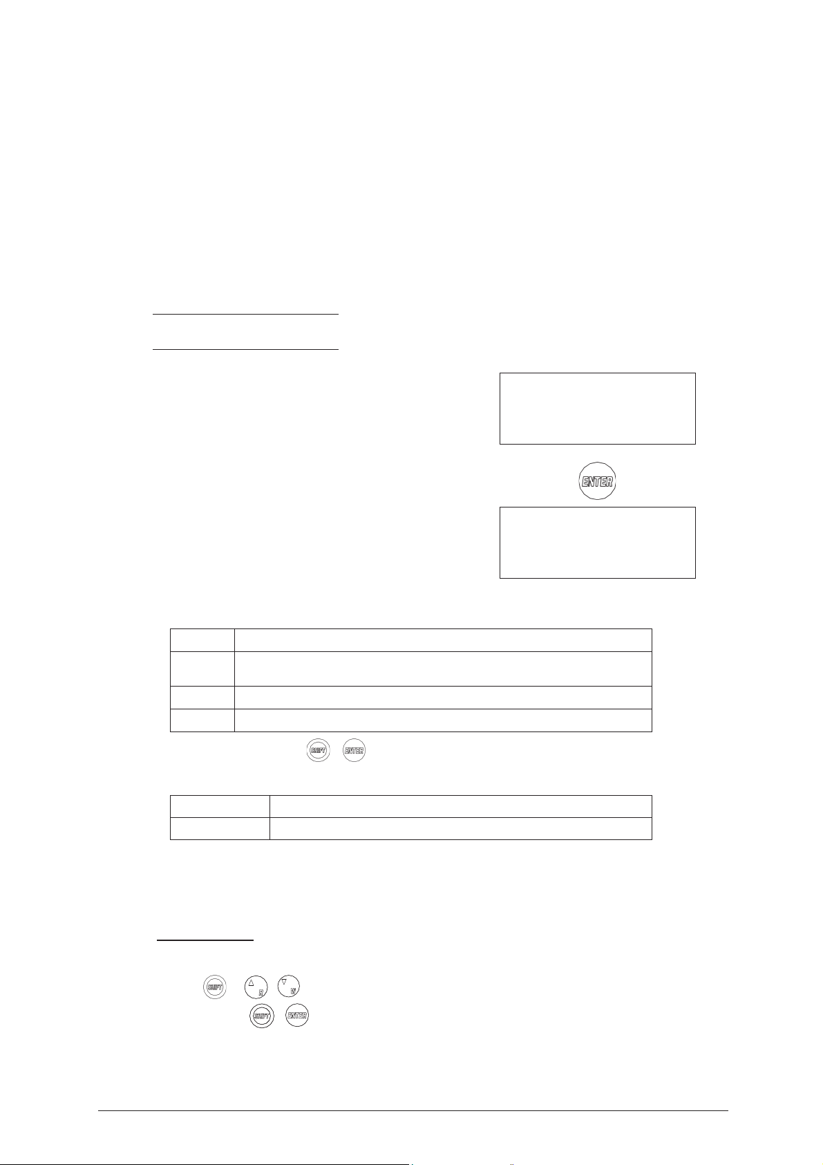
IDEA Operating Manual - English
5.18 USE OF THE M
In the previous pages the IDEA key-cutting machine operations and parts have been presented as a stand
alone machine with the data stored in the machine memory.
It is of interest to examine a very important function regarding connection to a PC so that the machine can
receive data directly.
The "Silca Keys Program" makes it possible to interface with the IDEA and transmit the cutting data required
and selected, through the powerful program made available. It is also possible to store the selected keys in
a special work queue (or file) so that they can be transmitted to the machine as soon as it is available.
Each combination sent to the IDEA corresponds to a step in the cutting process for the number of keys
entered on the PC.
When the cutting operation is finished for the number of keys set, a ‘+’ sign shows the end of the cycle.
When the IDEA is turned off in the middle of a work queue, the machine stores the status of the work done
in its memory.
When the machine is turned on again the unfinished cutting operations will be easily found with the number
of keys still to be cut.
NOTE: the key combinations transmitted by the Personal Computer cannot be altered by the
operator.
Q
UEUE FROM
Choose the function from the main menu by placing the
cursor on 3 “Queue from PC”.
PC - 3
ACHINE WITH
A P
ERSONAL COMPUTER
0 – Copy from Original
1 – Decode and Copy
2 – Insert the Cuts
3 – Queue from PC >>
001 Codes received
1 - [10] 1
2 - AH100 [45] 2
3 - A3456 [67] 3
Analysing the first line in the window above:
1
-/+
[10]
1
Progression for codes received
‘-‘ shows that the 3 keys set have not all been cut
‘+’ shows that the 3 keys set have all been cut
SSN
Number of pieces to cut
Press the [SHIFT+ENTER] + keys to see the ‘Data received’ list for each code transmitted, which
gives other data sent by the PC, such as:
Customer’s name Name of the customer assigned by the PC program in the HISTORIC archive
Art. Key article
Each key received by the PC has a set quantity (or number of pieces). The machine program decreases the
number with every key cut and stores the count in its memory even when the machine is turned off.
For this purpose a [START] key has been added in order to search for the first code in the list with a number
of cut keys lower than that set.
Operational keys
Arrow keys: to scroll the lines.
[SHIFT] + [arrows Up, Down] to scroll 4 lines at a time.
[SHIFT+ENTER] + keys to view customer data and key article for the code selected.
70 Copyright Silca 2004
Page 75

Operating Manual - English IDEA
Press ENTER:
Bit 1: 2
121 21212 121
Possible depths:
123456# [1]
Bit 2: 2
212 21212 212
Possible depths:
123456# [1]
SSN: 10 M1 Brass
Clamp: S1 - K1 Stop: 0
Cutter: 1.25
Pcs = 1/ 1 [START]
KEY
DECODING BY
With the use of a PC, i. and. with a much more complete collection of data, keys can be decoded as well as
cut. (Important: pay attention to the note for fitting the key).
SSN. 10
After launching the Silca Keys Program the decoding
function for SSN 10, appears on the machine display for a
few seconds:
then:
Press START:
PC
Waiting for
computer data
DECODE SSN 10
Original on right
Clamp:S100 A-B Dist.: 0
[START]
Decoding in progress
Bit 1
Decoding in progress
Bit 2
The data relating to key depth are transmitted to the PC for
processing only at the end of the decoding cycle.
Copyright Silca 2004 71
Decoding OK
See computer!
Page 76

IDEA Operating Manual - English
5.19 USE OF
In addition to the possibility to produce a copy of a key starting from a reading made by the
IDEA optic reader, it is also possible to produce a copy of a key starting from a reading
made by OPTIKA using the Key Reader Program or Silca key Program.
In the Key Reader Program, the “Copy key” control allows the operator to read the cuts on an original key
with the OPTIKA device and automatically forward all the necessary data with which to produce a copy with
IDEA.
The job will be received by the machine from the PC queue.
Note:
The job received in the PC queue will delete any existing job queue.
The OPTIKA device is unable to read cuts on the following types of keys:
• Shoulder stop (mortice)
• Special bit female
• Square stepped tip (FIAM)
• Rear stop
• MUEL pump keys
•Abus
•Abloy
• Tibbe
THE MACHINE WITH
OPTIKA
VIA
PC
- When transmission from the PC is over, the job will be viewed in the “PC QUEUE” menu.
- Make sure the job indicates the right type of key to be copied:
Types of keys legend:
[FAM] = Bit Stop Male
[FAF] = Bit Stop Female
[POM] = Pump
Press ENTER.
Note: for male keys with front stop the job received from the OPTIKA device is not complete,
the operator must select the right KEY TYPE to copy
1 CODES REC.
1 + OPTIKA [FAM]
.
SELECT TYPE OF KEY
- BIT STOP MALE
- SQUARE-SQUARE TIP
- SQUARE-ROUND TIP
- SMALL BIT
- Select the KEY TYPE from those shown. The machine will then be able to show the operator the right
adapter and download the relative program for cutting the key.
- Fit the key blank in accordance with all the procedures described in the manual for the chosen key type
and press START.
72 Copyright Silca 2004
Page 77
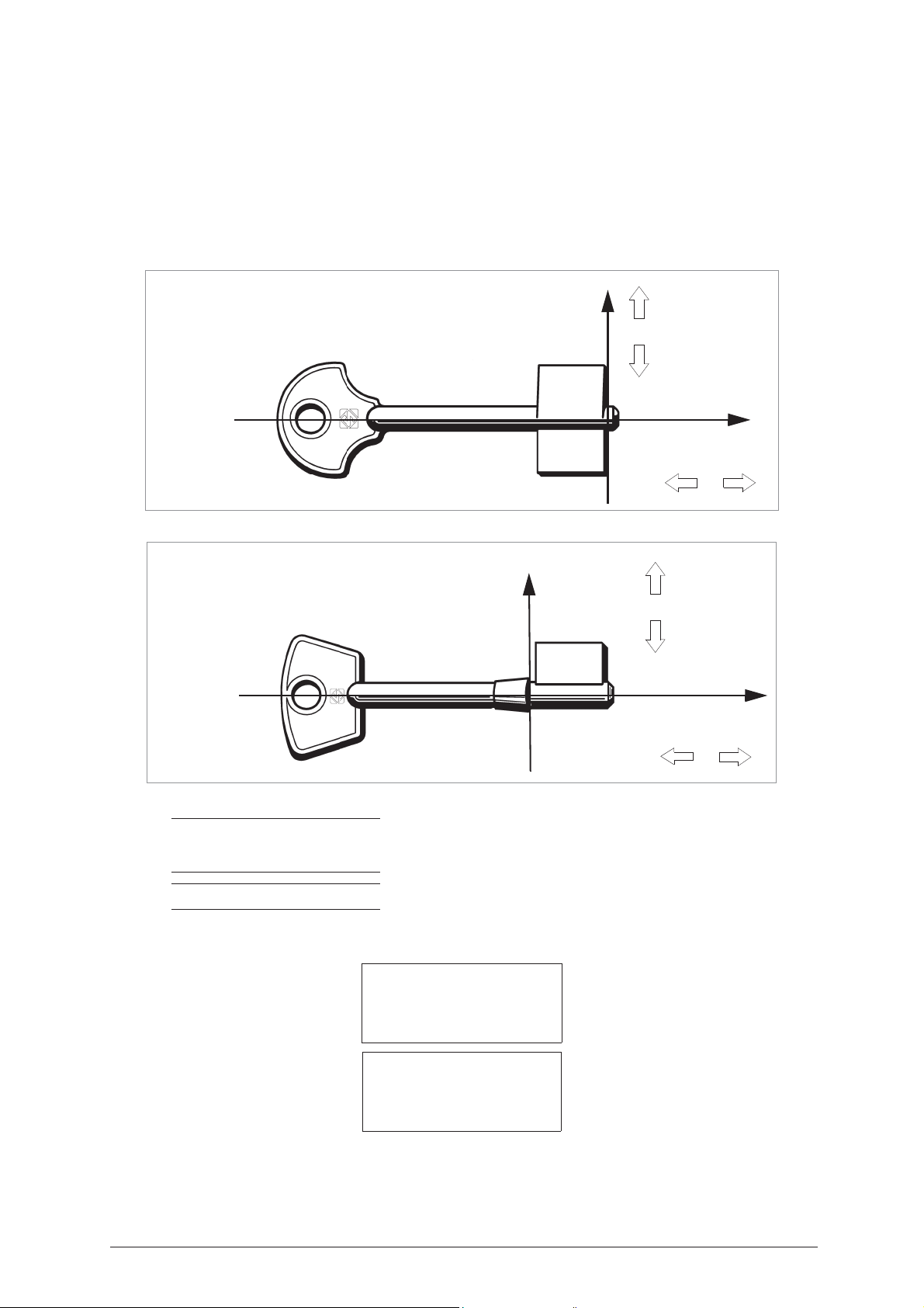
Operating Manual - English IDEA
X
Y
+
+
-
-
cut more
cut less
X
Y
+
+
-
-
5.20 G
D
The direction of compensation always refers to the key, of whatever type, or the device to which the
compensations are fitted. The reference axes for the direction of compensation are the key axis and stop 0
(tip). Positive compensations cause moving away from the reference zeroes (highest teeth and/or closest to
the tip), negative compensations cause moving towards them (lowest teeth and/or farthest from the tip).
Below is described a case of single or double bit keys.
Fig. 97
AUGING
EFINITIONS
Fig. 98
NOTE: Adjustments to a key held by an adapter are the sum of:
NOTE: MANUAL adjustments to the clamp are not considered when there is an ADAPTER fitted.
Use arrows [up, down] to scroll.
- automatic adjustments to the clamp
- manual adjustments to the adapter
1 - Clamps
2 - Cutter
3 - Adapter
Clamps
1: S1 - Rotating Jaw
2: S100 - Reader Jaw
Copyright Silca 2004 73
Page 78
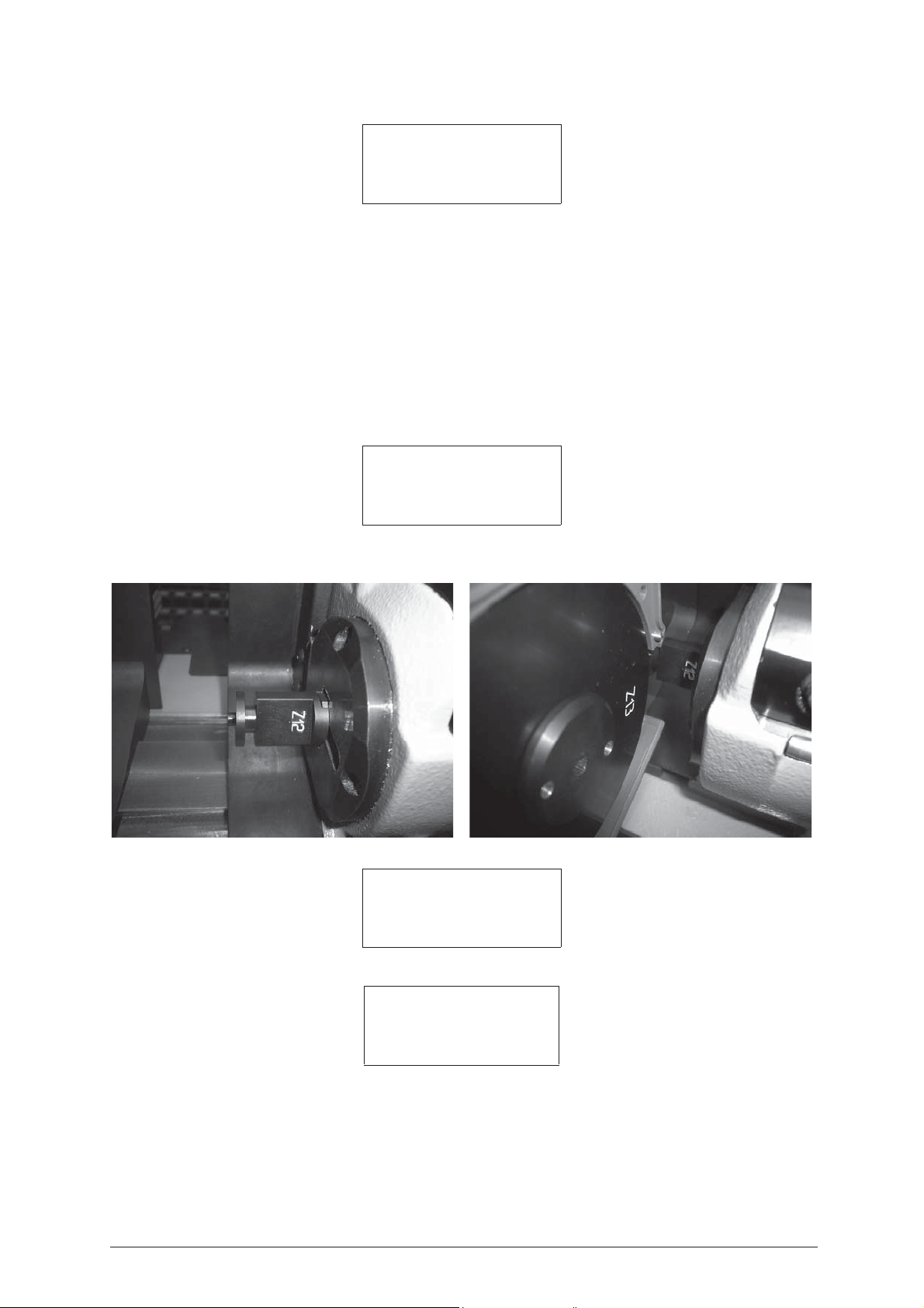
IDEA Operating Manual - English
Select S1:
Clamps: S1 - K1
Adjustment: B= +000
X=+00 Y1=+06 Y2=+06
To calibrate [START]
Clamp: S1 - K1
SHIFT+ENTER
START
= press START to begin the automatic gauging procedure for the CLAMP-TAILSTOCK unit, if
= unit comprising clamp S1 and interchangeable tailstock K1.
= to go to the other interchangeable tailstock used with clamp S1, if applicable.
applicable.
Place the pointer at the side of the parameter to be edited with the arrows or with [ENTER] and edit the
parameters using the following keys:
SHIFT + [arrow Up] increases the value within:
+300 hundredths of a mm or hundredths of a degree (axis B)
+ 20 cent.mm X/Y1/Y2
SHIFT + [arrow Down] decreases the value within:
- 300 hundredths of a mm or hundredths of a degree (axis B)
-20 cent.mm. X/Y1/Y2
CLEAR to zero the value
[ENTER] in the last field is used to quit the window and show the message requiring the editing to be saved:
Save
adjustment ?
No=STOP Yes=ENTER
ATTENTION: when [STOP] is pressed the new measurements are not saved; the previous gauging values
therefore remain valid
.
Fig. 99
Select S100
Clamp: S100
Adjustments:
X=+04 Y1=+04 Y2=+04
FOR K2
TAILSTOCK
:
Clamps: S1 - K1 >>
Adjustments: B=+000
X=+00 Y1=+00 Y2=+00
To calibrate [START]
- Press [SHIFT + ENTER]
Clamp: S1 - K1
>>
= press [SHIFT+ENTER] to go to the other interchangeable tailstocks used with the S1 clamp, if
= unit comprising the S1 clamp and K1 interchangeable tailstock.
applicable.
Clamp: S1 - K2
74 Copyright Silca 2004
= unit comprising the S1 clamp and K2 interchangeable tailstock
Page 79
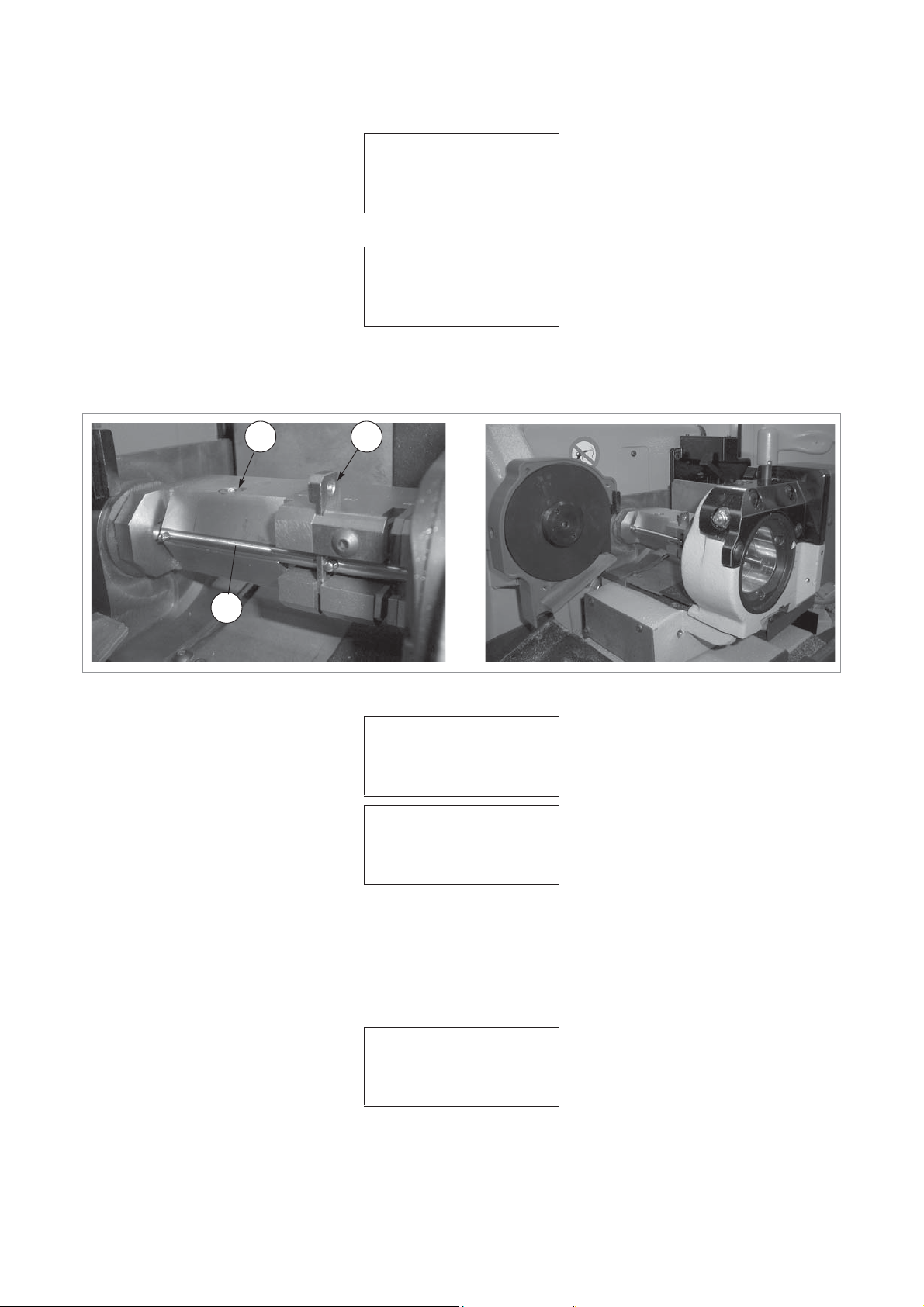
Operating Manual - English IDEA
W2
Z
13
P
Z15
Clamps: S1 - K2
Adjustments: B=+000
X=+00 Y1=+00 Y2=+00
To calibrate [START]
START
= press START to begin the automatic gauging procedure for the CLAMP TAILSTOCK unit.
Clamps: S1 - K2
Install Z15 and Z13
See operating manual
[START]
Template Z13
Template Z15
= fit in place of the cutter (fig. 100).
= fit on the S1-K2 clamp as if it were a key (fig. 100). Use the plate (P) as a point of reference
in position 2 with the second pin on the template up against it. Tighten the screw (W2) with the (T4) wrench.
Replace the (T4) wrench in its seat.
Fig. 100
Press START
Clamps: S1 - K2
Detection
In progress
Clamps: S1 – K2
Adjustments: B=+000
X=+02 Y1=+02 Y2=+04
To calibrate [START]
Position the pointer at the side of the parameter to be edited with the arrow keys or [ENTER] and use the
following keys to edit the parameters:
[SHIFT] + [arrow up]:increases the value within
(axis B)
+ 20 cent.mm X/Y1/Y2
[SHIFT] + [arrow down]: decreases the value within
(axis B)
- 20 cent.mm X/Y1/Y2
+ 300 hundredths of a mm or hundredths of a degree
- 300 hundredths of a mm or hundredths of a degree
[CLEAR]:to zero the value
[ENTER]:in the last field to quit the window so that the query Save? appears for the edited data:
Save
adjustment ?
No=STOP Yes=ENTER
ATTENTION: if [STOP] is pressed the new measurements are not saved; the previous gauging values therefore
remain valid.
Copyright Silca 2004 75
Page 80

IDEA Operating Manual - English
5.21 C
Scroll with the arrows.
[ENTER] = to view the cutter parameters.
SHIFT + [ENTER] = to set the current cutter.
* = shows the cutter currently selected
SHIFT + [arrow Up ] increases the diameter within +20 hundredths of a mm
SHIFT + [arrow Down] decreases the diameter within - 20 hundredths of a mm
CLEAR to zero the value
[ENTER] in the last field is used to quit the window and show the message requiring the editing to be saved:
UTTERS
Cutter
1: PL 1.25 (0.492)
2: PL 1.00 (0.393)
3: PL 1.50 (0.590)
4: PL 1.70 (0.669)
5: PL 1.90 (0.748)
6: PL 2.00 (0.787)
01*- PL 1.25
Thickness: 125
Diameter: 10000
Adjust. Diam.: +00
Save
adjustments ?
No=STOP Yes=ENTER
ATTENTION: when [STOP] is pressed the new measurements are not saved; the previous gauging values
therefore remain valid.
76 Copyright Silca 2004
Page 81
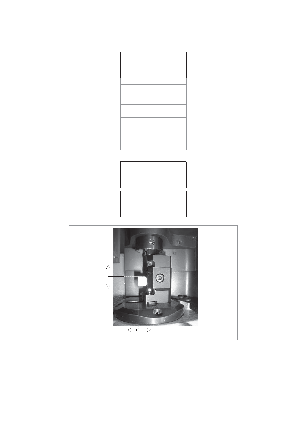
Operating Manual - English IDEA
-+Y
X
+
-
E1
5.22 A
Scroll with the arrows.
[ENTER] = to view the adapter parameters.
DAPTERS
Adapters
1: E1 - Mortice
1: E2 - Bit Stop Female
3: E3 - Pump (cutting)
4: E4 - Muel (Cutting)
5: E5 - Fiam (cutting)
6: E6 - Fiam (reading)
7: E7 - Pump (reading)
8: E8 - Muel (reading)
9: E9 - Chubb RKS (C)
10: E9 - Chubb RKS (R)
11: E10 - Small Bit (C)
12: E11 - Rear Stop (R)
13: E15 - Special Bit F (C)
14: E16 - Special Bit F (R)
Adapter
Side: cutting
Adjustments: B=+00
X=+00 Y1=+00 Y2=+00
E1
Fig. 101
Save
adjustments ?
No=STOP Yes=ENTER
SHIFT + [arrow Up] increases the value within:
SHIFT + [arrow Down] decreases the value within:
CLEAR to zero the value
[ENTER] in the last field is used to quit the window and show the message requiring the editing to be saved:
+300 hundredths of a mm or hundredths of a degree (axis B)
- 300 hundredths of a mm or hundredths of a degree (axis B)
Copyright Silca 2004 77
X/Y1/Y2 = +20 cent.
X/Y1/Y2 = - 20 cent.
Page 82
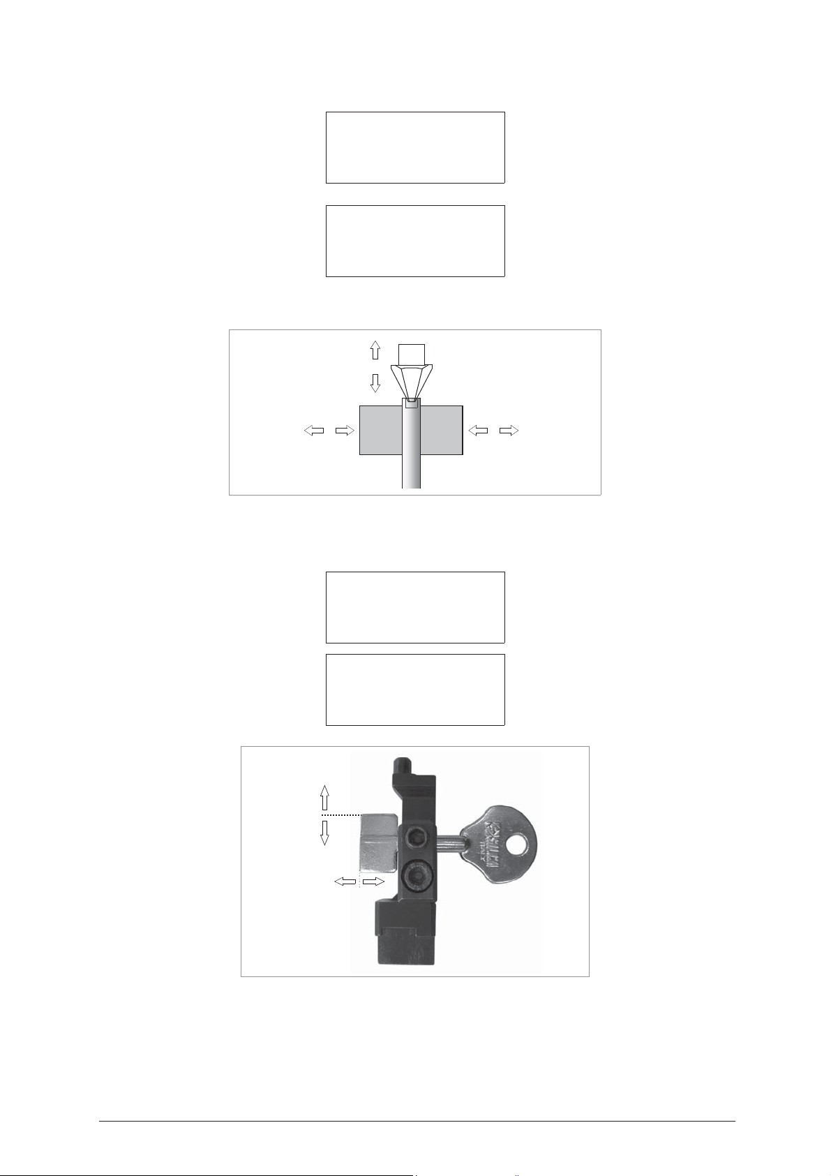
IDEA Operating Manual - English
Y2
-+
Y2Y1
Y1
-+
X
-
+
Example:
Adapter
E2
Side: cutting
Adjustment: B=+00
X=+00 Y1=+00 Y2=+00
Save
adjustment ?
No=STOP Yes=ENTER
ATTENTION: when [STOP] is pressed the new measurements are not saved; the previous gauging values
therefore remain valid.
Fig. 102
Example:
Adapter
Side: cutting
Adjustment: B=+00
X=+00 Y1=+00 Y2=+00
Save
adjustment ?
No=STOP Yes=ENTER
+
X
-
+
-
Y
E3
Fig. 103
78 Copyright Silca 2004
Page 83
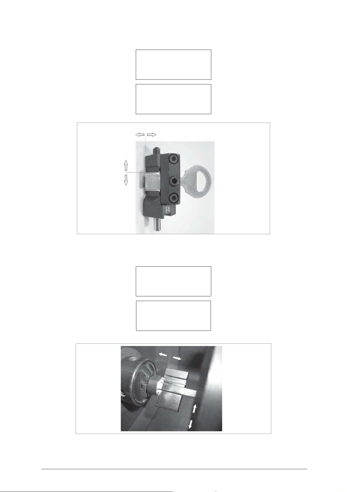
Operating Manual - English IDEA
X
+
-
-
+
Y
Y
-
-
X
+
+
Example
:
Adapter
Side: reading
Correzioni:
X=+00 Y1=+00 Y2=+00
le correzioni ?
No=STOP Si=ENTER
E4
Salvare
Fig. 104
Example:
Adapter
Side: cutting
Adjustment: B=+00
X=+00 Y1=+00 Y2=+00
adjustment ?
No=STOP Yes=ENTER
E5
Save
Fig. 105
Copyright Silca 2004 79
Page 84
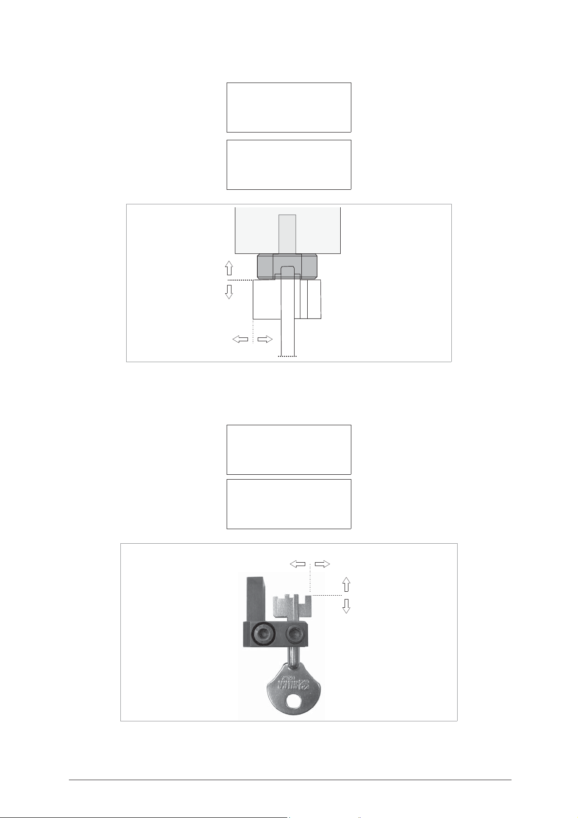
IDEA Operating Manual - English
E6
Y
-
+
X
-
+
Example:
Fig. 106
Adapter
Side: reading
Adjustment:
X=+00 Y1=+00 Y2=+00
adjustement ?
No=STOP Yes=ENTER
E6
Save
Example:
Adapter
Side: reading
Adjustments:
X=+00 Y1=+00 Y2=+00
adjustment ?
No=STOP Yes=ENTER
Save
-
E7
+
Y
+
X
-
Fig. 107
80 Copyright Silca 2004
Page 85
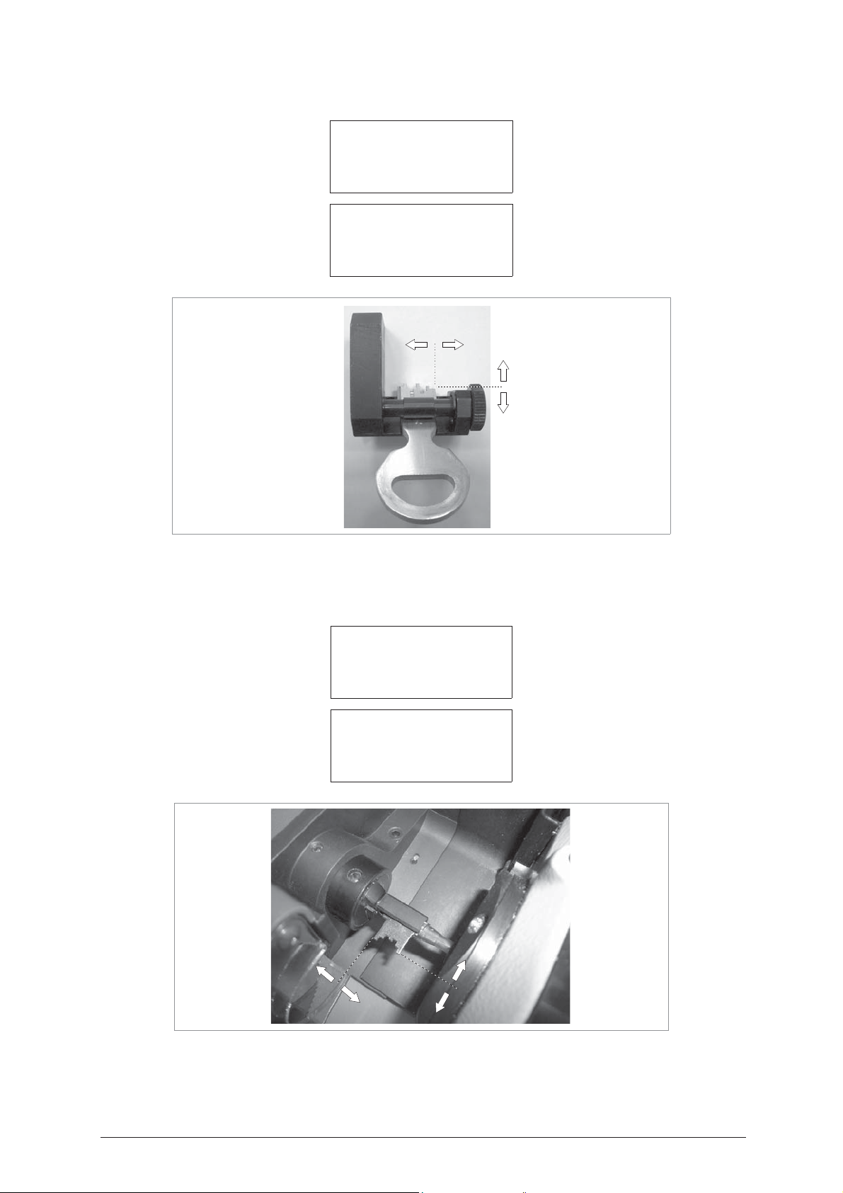
Operating Manual - English IDEA
Y
-
+
X
-
+
Example
:
Adapter
Side: reading
Correzioni:
X=+00 Y1=+00 Y2=+00
le correzioni ?
No=STOP Si=ENTER
Salvare
-
Y
E8
+
+
X
-
Fig. 108
Example:
Adapter
Side: cutting
Adjustment: B=+00
X=+00 Y1=+00 Y2=+00
adjustment ?
No=STOP Yes=ENTER
E9
Save
Fig. 109
Copyright Silca 2004 81
Page 86
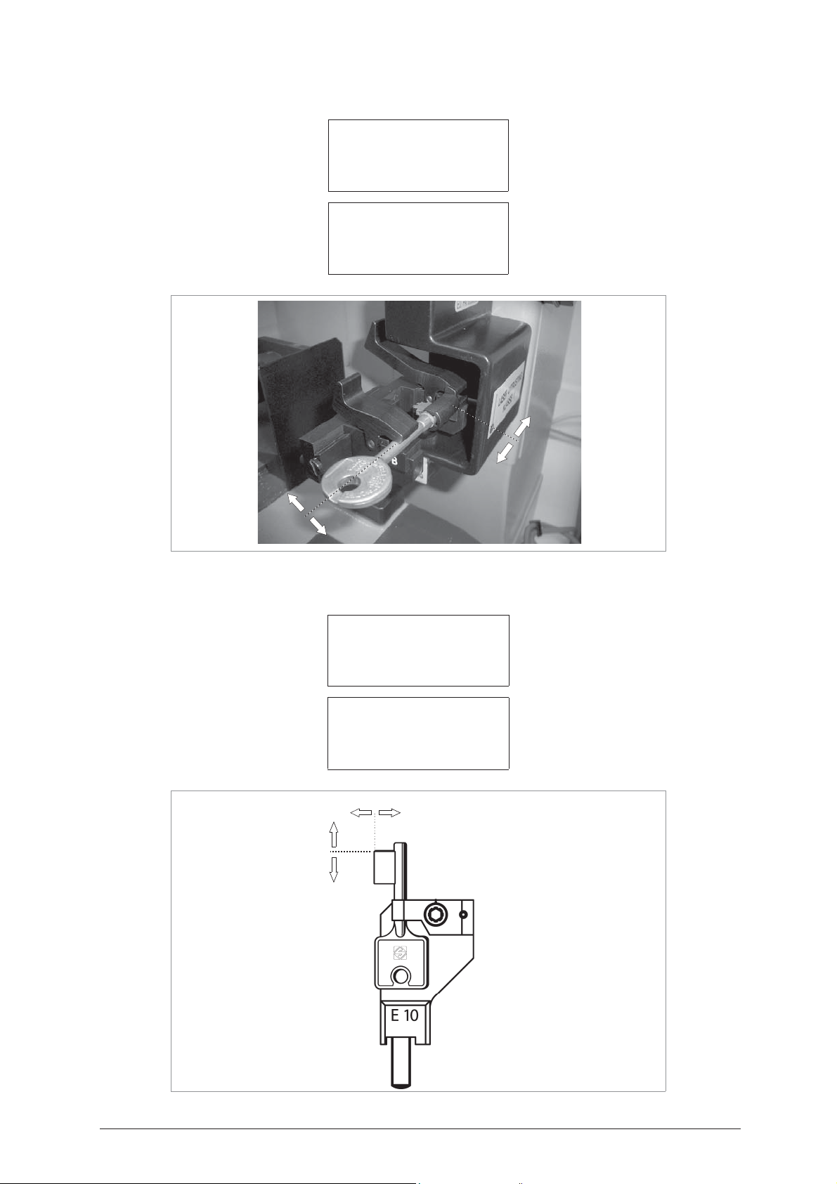
IDEA Operating Manual - English
Y
+
-
X
-
+
X
+
-
-
+
Y
Example:
Adapter
Side: reading
Adjustments:
X=+00 Y1=+00 Y2=+00
adjustements ?
No=STOP Yes=ENTER
E9
Save
Fig. 110
Example
:
Adapter
Side: cutting
Adjustments:
X=+00 Y1=+00 Y2=+00
adjustements ?
No=STOP Yes=ENTER
E10
Save
Fig. 111
82 Copyright Silca 2004
Page 87
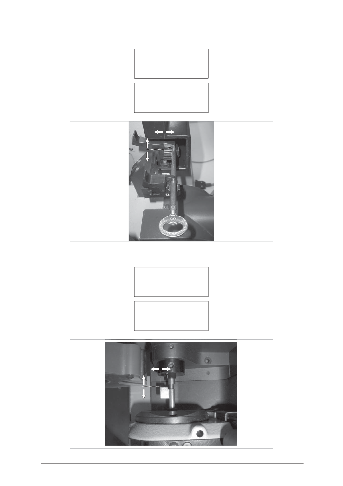
Operating Manual - English IDEA
X
+
-
-
+
Y
Example
:
Adapter
Side: reading
Adjustments:
X=+00 Y1=+00 Y2=+00
adjustements ?
No=STOP Yes=ENTER
-
Save
+
Y
E11
+
X
-
Fig. 112
Example
:
Adapter
Side: cutting
Adjustments:
X=+00 Y1=+00 Y2=+00
adjustements ?
No=STOP Yes=ENTER
E15
Save
Fig. 113
Copyright Silca 2004 83
Page 88
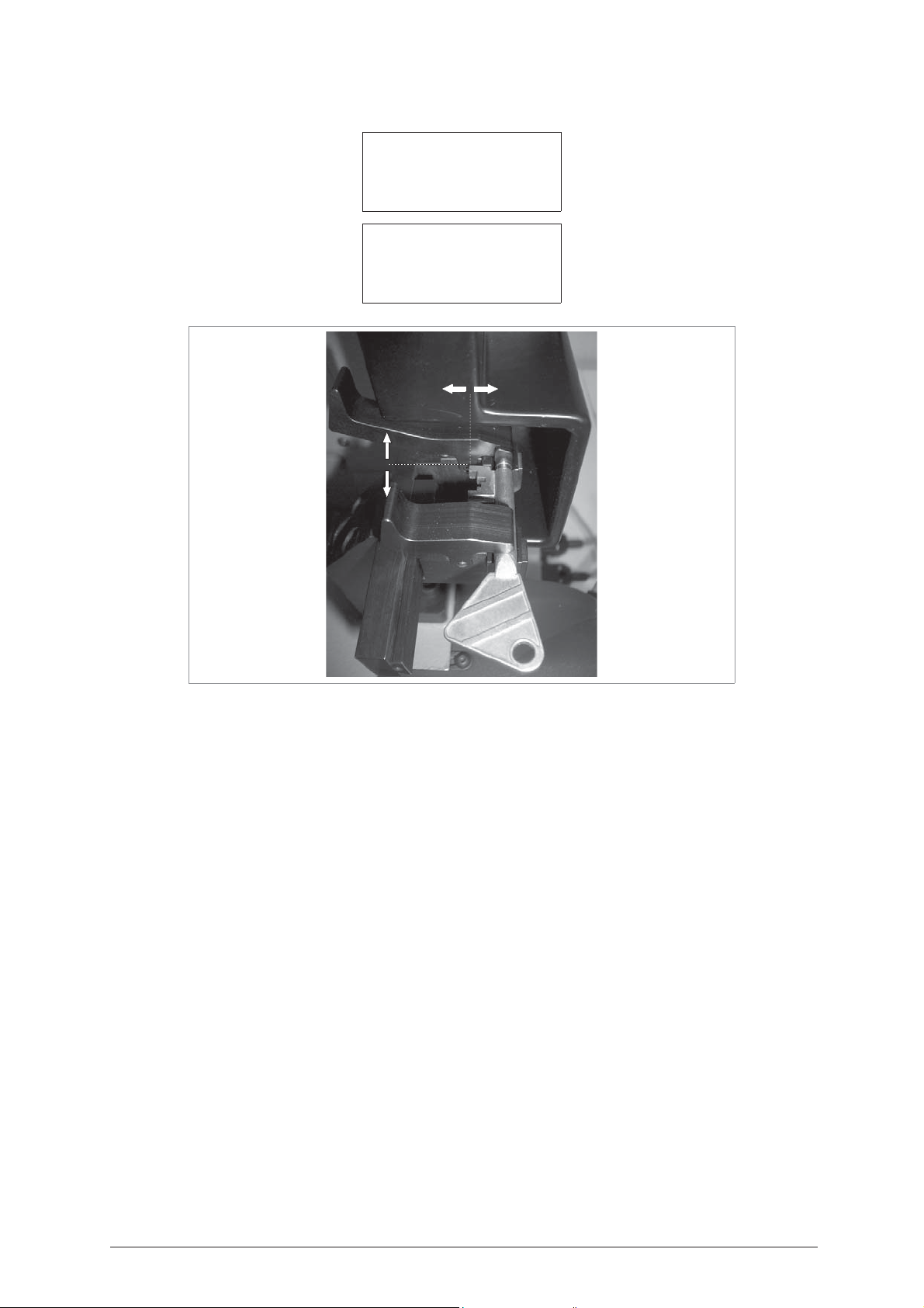
IDEA Operating Manual - English
Example
:
Adapter
E16
Side: reading
Adjustments:
X=+00 Y1=+00 Y2=+00
Save
adjustements ?
No=STOP Yes=ENTER
+
-
Y
+
X
-
Fig. 114
84 Copyright Silca 2004
Page 89

Operating Manual - English IDEA
6 MAIN MENU TEST FUNCTIONS
1 - Machine zero points
2 - Test
T
EST
1 - Optical reader
2 - X axis motor
3 - Y axis motor
4 - B axis motor
5 - Cutter motor
6 - X axis sensor
7 - Y axis sensor
8 - B axis sensor
9 - X axis photocell
10 - Y axis photocell
11 - (T) wrench micro
12 - Protective shield microsw.
13 - Electric contact
14 - Keypad
15 - Display
16 - Clamp Code
17 - Inlets
18 - Outlet 1
19 - Outlet 2
20 - Outlet 3
21 - Outlet 4
22 - Serial port
Copyright Silca 2004 85
Page 90

IDEA Operating Manual - English
6.1 T
ATTENTION: this “Test” chapter serves as a check on any errors/anomalies that could occur on the machine
EST
A TEST menu is incorporated in the machine, provided for finding faults and making checks.
1 - Machine zero points
2 - Test
(ch. 7.1, page 119).
From the main menu choose the function by placing the
pointer on “5 - Maintenance”
.
0 – Copy from Original
1 – Decode and copy
2 – Insert the Cuts
3 – Queue from PC >>
4 – Calibrations
5 – Maintenance
6 – Options
ENTER
Select “2 - Test”.
1 – Machine zero points
2 – Test
ENTER
• Test 1: OPTICAL READER
Carefully follow the instructions that are on the machine’s display. Check that the optical reader’s status
changes from OFF to ON.
NOTE: if the OFF/ON transition is not made, contact Silca’s Technical Assistance Dept.
• Test 2: X AXIS MOTOR
Carefully follow the instructions on the display and check that the X axis carriage moves.
ATTENTION: during this test all the end of run controls are disabled; avoid moving the carriage up against its
mechanical stops.
NOTE: if the motor does not start, contact Silca’s Technical Assistance Dept.
• Test 3: Y AXIS MOTOR
Carefully follow the instructions on the display and check that the Y axis carriage moves.
ATTENTION: during this test all the end of run controls are disabled; avoid moving the carriage up against its
mechanical stops.
NOTE: if the motor does not start, contact Silca’s Technical Assistance Dept.
• Test 4: B AXIS MOTOR
This Test can be carried out only when the S1 clamp is installed on the machine.
86 Copyright Silca 2004
Page 91

Operating Manual - English IDEA
• Test 5: CUTTER MOTOR
Carefully follow the instructions on the display and check that the cutter motor works.
- The test is OK if speed is approximately 2880.
- If the cutter is turning and the display shows a speed of “0”, the motor photocell is faulty and must be
replaced.
NOTE: if the cutter motor does not start, contact Silca’s Technical Assistance Dept.
• Test 6: X AXIS SENSOR
- the machine’s display should show ON when the carriage is drawn away from the machine (towards the
operator).
- the machine’s display should show OFF when the carriage is pushed all the way in towards the machine.
NOTE: if the OFF/ON transition is not made, contact Silca’s Technical Assistance Dept.
• Test 7: Y AXIS SENSOR
- the machine’s display should show OFF when the carriage is moved all the way to the right.
- the machine’s display should show ON when the carriage is moved all the way to the left.
NOTE: if the OFF/ON transition is not made, contact Silca’s Technical Assistance Dept.
• Test 8: B AXIS SENSOR (rotating)
- with rotation in the standard position the display shows OFF.
- using a screwdriver to turn screw (M7) (fig. 145, page 128) clockwise the display goes to ON.
• Test 9: X AXIS PHOTOCELL
Slowly push the X axis carriage manually towards the machine’s chassis checking that the machine’s display
indicates ON to OFF.
NOTE: if the OFF/ON transition is not made, contact Silca’s Technical Assistance Dept.
• Test 10: Y AXIS PHOTOCELL
Slowly push the Y axis carriage manually from its right all the way to its left checking that the machine’s
display indicates ON to OFF.
NOTE: if the OFF/ON transition is not made, contact Silca’s Technical Assistance Dept.
• Test 11: (T) WRENCH MICRO
Carefully follow the instructions that are on the machine’s display. Check that the status changes from OFF
to ON.
NOTE: if the OFF/ON transition is not made, contact Silca’s Technical Assistance Dept.
• Test 12: PROTECTIVE SHIELD MICROSWITCH
Raise and lower the protective shield, checking that the machine display shows first OFF then ON.
• Test 13: ELECTRIC CONTACT
Use any metal conductor to create a connection between the cutter and the clamp, checking that the
machine display shows first OFF then ON.
• Test 14: KEYBOARD
One at time, press all the keys (except STOP) checking that an asterisk (*) appears for each key pressed.
Press the STOP key for last.
• Test 15: DISPLAY
All points on the display should be obscured.
• Test 16: CLAMP CODE
Check on the display that ø:ON is code:1.
• Test 17: INLETS
To use the test properly, consult the literature provided with the specific optional accessories.
Copyright Silca 2004 87
Page 92

IDEA Operating Manual - English
• Test 18: OUTLET 1
To use the test properly, consult the literature provided with the specific optional accessories.
• Test 19: OUTLET 2
To use the test properly, consult the literature provided with the specific optional accessories.
• Test 20: OUTLET 3
To use the test properly, consult the literature provided with the specific optional accessories.
• Test 21: OUTLET 4
To use the test properly, consult the literature provided with the specific optional accessories.
• Test 22: SERIAL PORT
Check that the machine display shows OFF.
Fit the special serial test connector (Z4) provided to the machine serial port, checking that the display shows
first OFF then ON.
88 Copyright Silca 2004
Page 93
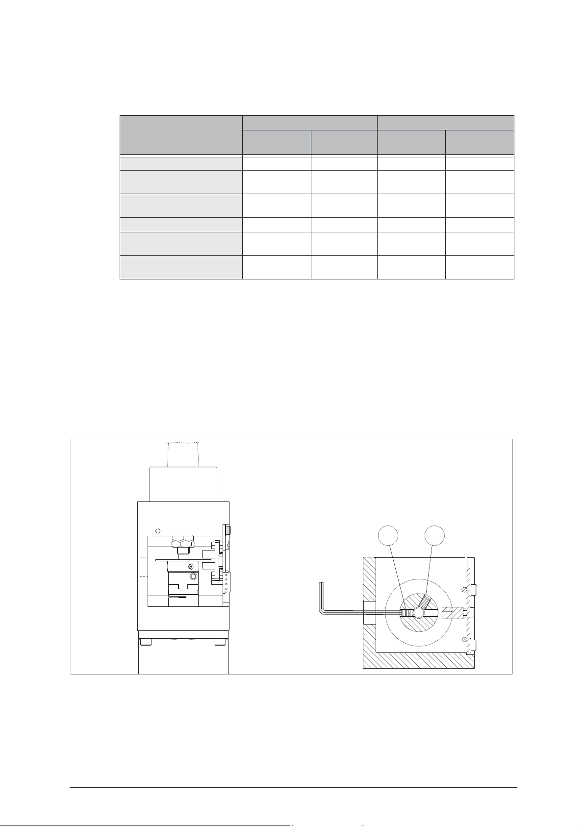
Operating Manual - English IDEA
G1 G2
6.1.1 Machine zero points
With the use of regulating templates (ch. 1.5, page 10) the machine provides a ‘self-setting’ procedure.
These procedures must be carefully carried out following the descriptions and illustrations indicated below.
MACHINE ZEROES CALIBRATING
EVENT
CUTTING UNIT
Replacement of photocells YES YES NO NO
Replacement of
YES YES YES YES
the electronic board
Replacement of
NO YES NO NO
the Optical Reader unit
Replacement of sensors YES YES YES YES
Replacement of the cutter
YES YES NO NO
shaft
Replacement of the ball
YES YES NO NO
screws
P
RELIMINARY OPERATIONS
1)
turn the machine off and unplug it from its power supply cable
2) remove the back panel (ch. 7.8, page 126).
3) loosen the (G1) and (G2) grub screws that secure the X axis photocell disk (fig. 115).
4) remove the bottom panel (ch. 7.9, page 126).
5) disconnect the (J1) Y axis cable from the carriage (fig. 116).
6) unscrew the 3 (B5) fixing screws and remove the Y axis protective cover by pulling it in the direction shown
in fig. 116.
7) loosen the (G3) and (G4) grub screws that secure the Y axis photocell disk (fig. 118, page 91).
8) plug the Y axis (J1) cable (fig. 116) and the machine’s power supply cable back into place.
9) turn the machine on and carry on with the procedures described on page 90.
READING
UNIT
CLAMPS CUTTERS
.
Fig. 115
Copyright Silca 2004 89
Page 94
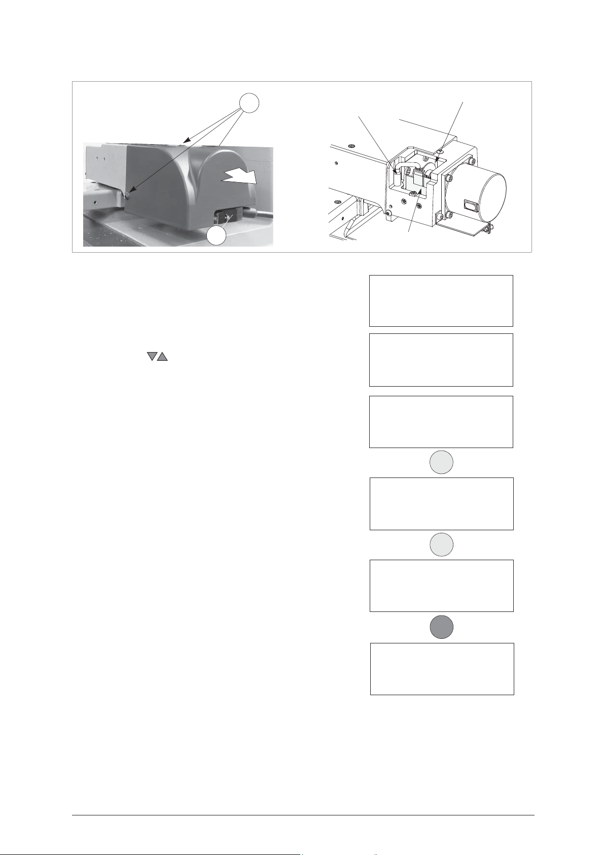
IDEA Operating Manual - English
Fig. 116
B5
Y axis sensor
J1
CUTTING UNIT
1)
enter the “Maintenance” #5
2)
select “Machine zero points” #2
Operational keys:
use the arrow keys to move the cursor to the option
required and press ENTER or directly press the numbered
key corresponding to the option number.
.
.
Y axis photocell disk
Y axis photocell
4 - Calibrations
5 - Maintenance
6 - Options
1 - Test
2 - Machine ‘0’ point
3)
select ‘Cutting unit’ #1
insert the (Z12) template
4)
5)
remove the cutter and insert the (Z13) template into
place (
fig. 99).
manually move the X and Y axis up until the (Z12) and
6)
(Z13) templates make contact
7)
lower the protective shield and press START
.
(fig. 99, page 74).
(fig. 117).
.
ATTENTION: check that both the (Z13) and (Z12) templates make
perfect contact. If this does not occur the display will
show an error message.
1 - Cutting unit
2 - Reading unit
ENTER
Install Z12 & Z13
templates.
See operating manual.
[ENTER]
ENTER
Move axis
up until contact is made
See operating manual.
[START]
START
ERROR 10
No contact made.
See operating manual.
90 Copyright Silca 2004
Page 95
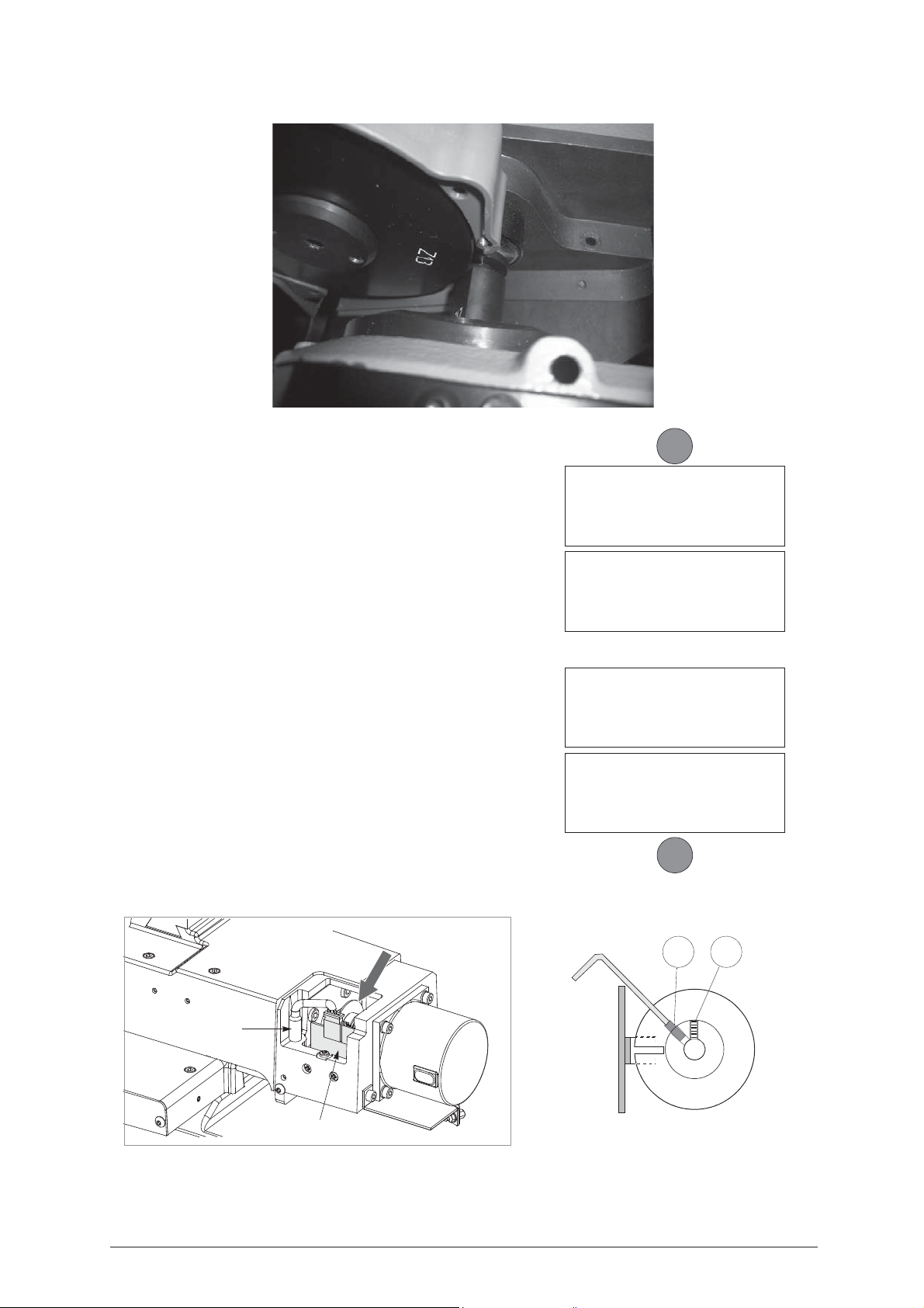
Operating Manual - English IDEA
Fig. 117
- the machine will take the X and Y axes to a predefined
position.
-
the operator must manually rotate the X and Y photocell
disks up until the cut in the disks face the photocells
card
.
Y axis photocell:
•
manually turn the Y axis disk
display’s description changes from OFF to ON
(fig. 118) up
until the
.
• use the provided allen key to tighten the (G3) grub screw
(fig. 118).
X axis photocell:
•
manually turn the
the display’s description changes from OFF to
X
axis disk
(fig. 115, page 89) up
ON.
until
• use the provided allen key to tighten the (G1) grub screw
(fig. 115).
8)
lower the protective shield
9)
press
START.
-
the machine goes on to a new position and is ready for
regulating the sensors
.
.
START
Pos. Photocell.
TZX=OFF TZY=OFF
See operating manual.
[START]
Pos. Photocell.
TZX=OFF TZY=ON
See operating manual.
[START]
Pos. Photocell.
TZX=OFF TZY=OFF
See operating manual.
[START]
Pos. Photocell.
TZX=ON TZY=ON
See operating manual.
[START]
START
Fig. 118
G3 G4
Y axis sensor
Y axis photocell
Copyright Silca 2004 91
Page 96
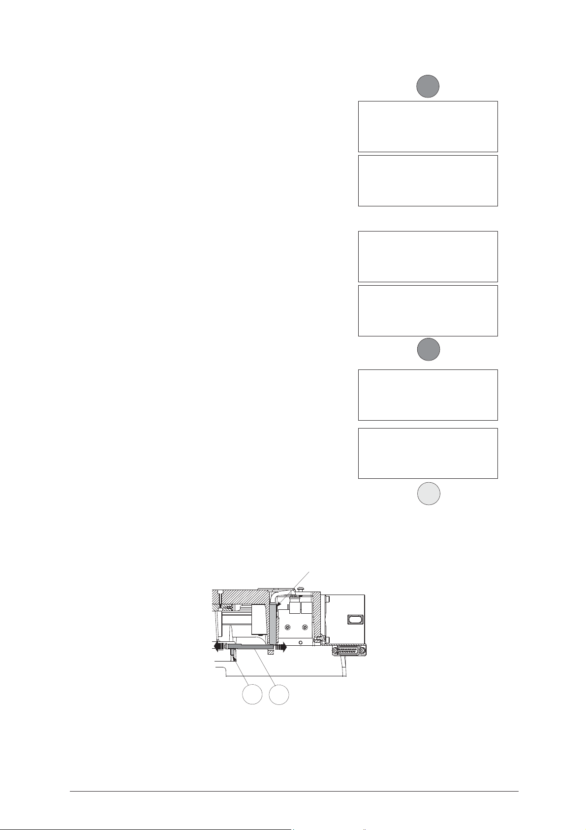
IDEA Operating Manual - English
Regulating the Y axis sensor:
•
raise the protective shield
.
START
• use the provided allen key to loosen the (C1) grub screw;
manually rotate the (C2) rod (fig. 119) in both directions
up until the changeover point from OFF to ON is found.
•
tighten the (C1) grub screw to secure the rod
.
Pos. sensors.
ICX=OFF ICY=OFF
See operating manual.
[START]
Pos. sensors.
ICX=OFF ICY=ON
See operating manual.
[START]
Regulating the X axis sensor:
•
carefully tip the machine over
• remove the bottom panel by unscrewing all 8 securing
screws.
• loosen the (C3) screw (fig. 120) that secures the sensor
support plate. Manually move the sensor up until the
display’s description goes from OFF to ON.
• tighten the (C3) screw to secure the plate back into
place.
•
re-position the machine back on its workbench and
lower the protective shield
•
press
START.
-
the ‘machine’s zero’ settings are detected by electric
contact
.
.
Pos. sensors.
ICX=OFF ICY=OFF
See operating manual.
[START]
Pos. sensors.
ICX=ON ICY=ON
See operating manual.
.
[START]
START
Zero detection
in progress!
10) when the operation has been completed, the display will
show the measured quotes.
11) press ENTER to save
12) manually turn the Y axis disk to get access to the (G4)
grub screw (fig. 118).
13) manually turn the X axis disk to get access to the (G2)
grub screw (fig. 118).
Measured quotes:
X=4444 Y=3333
Save measurements?
No=STOP Yes=ENTER
ATTENTION: if the STOP key is pressed, the new settings will be
lost. If so, only the previous setting values will remain
valid.
Y axis sensor
C1
C2
Fig. 119
ENTER
92 Copyright Silca 2004
Page 97
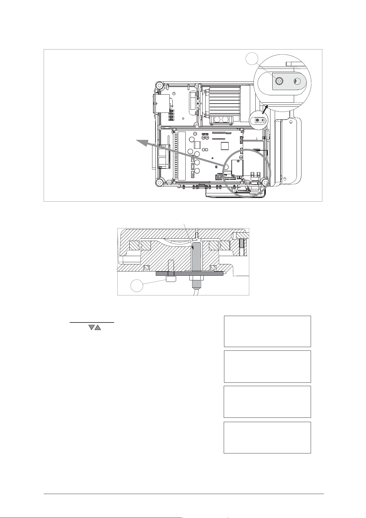
Operating Manual - English IDEA
C3
bottom view
ATTENTION:
if it is necessary to work close
to this area with the machine
turned on (e.g. to regulate the
X axis sensor) take great care
not to touch any components
on the machine’s electronic
boards as it is connected to
230/110 Volts.
Fig. 120
Fig. 121
Y axis sensor
C3
R
EADING UNIT
Operational keys:
use the keys to move the cursor to the option required
and press ENTER or directly press the numbered key
corresponding to the option number.
1)
enter the ‘Maintenance’ menu #5
select ‘Machine zero points” #2
2)
.
.
4 - Calibrations
5 - Maintenance
6 - Options
1 - Test
2 - Machine ‘0’ point
3)
select ‘Reading unit’ #2
.
4) install the (Z14) template.
- install A and B clamps (S100)
1 - Cutting unit
2 - Reading unit
Install A & B clamps
and Z14 template
See operating manual.
[START]
Copyright Silca 2004 93
Page 98
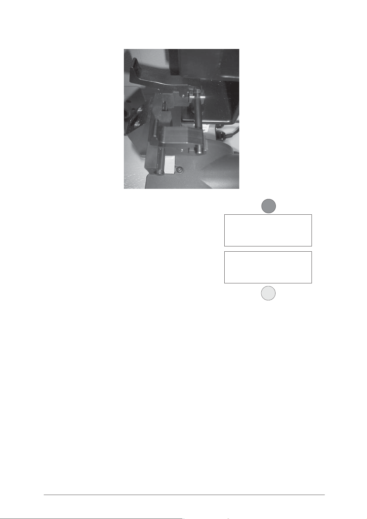
IDEA Operating Manual - English
Fig. 122
5) lower the protective shield and press START.
START
- the ‘machine’s zero’ settings are detected by the optical
reader.
Zero detection
in progress!
- when this operation is completed, the machine’s display
will show the measured quotes
Measured quotes:
ATTENTION: if the STOP key is pressed, the new settings will be
lost. If so, only the previous setting values will remain
valid.
X=4444 Y=3333
Save measurements?
No=STOP Yes=ENTER
ENTER
94 Copyright Silca 2004
Page 99

Operating Manual - English IDEA
D
IMENSION CHECK
To check the machine’s precision, proceed as follows:
Choose “2 Insert cuts” from the main menu and press ENTER.
Choose SSN = 10 and press ENTER.
Enter the depth for bit 1 as in the example:
– CUTTING TEST
0 - Copy from Original
1 - Decode and Copy
2 - Insert cuts
3 - Queue from PC >>
SSN = 10 (Cut)
Make =
= CISA
CSL-CSLC-5CS1-5CS2
Bit 1: 2 (Symm. F-R)
# #
Possible depths
123456# (1)
Bit 1: 2 (Symm. F-R)
111#66666#111
Possible depths
123456# (8)
Press ENTER
Bit 2: 2 (Symm. F-R)
…#…..#…
Possible depths
123456# (1)
Enter the depth for bit 2 (the same as bit 1) as in the example:
Bit 2: 2 (Symm. F-R)
111#66666#111
Possible depths
123456# (8)
Press ENTER
SSN: 10 M1 Brass
Clamp: S1 – K1 Stop: 0
Cutter: 1.25
Pz. 1 / 1 (START)
Fit the key blank into the clamp S1, then press START.
Cutting in progress
Copy: 1 of: 1
Bit 1
Cutting in progress
Copy: 1 of: 1
Bit 2
Copy 1 of 1
finished
More copies ?
No=STOP Yes=ENTER
Copyright Silca 2004 95
Page 100
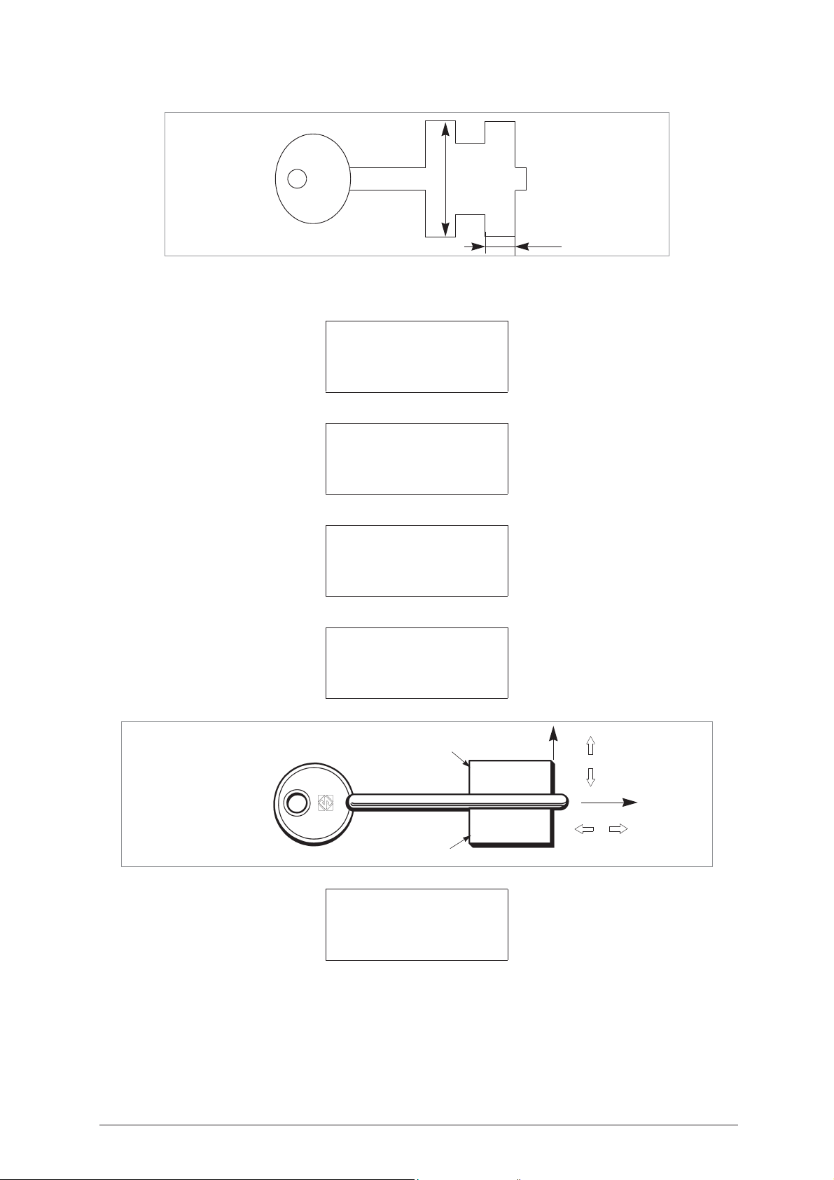
IDEA Operating Manual - English
X
-
+
Y
+
-
M1
M2
Y1
Y2
Press STOP, remove the key and use a centesimal gauge to measure it.
20,40
7,60
Fig. 123
Measurement X should be 7,60 mm (….inch), +/- 0,03 mm
Measurement Y (Y1+Y2) should be 20,40 mm (…inch) +/- 0,03 mm
If this is not the case, e.g. X = 7,70 and Y = 20,30 proceed as follows:
4 - Calibrations
5 - Maintenance
6 - Options
Choose “4 Calibrations” from the main menu and press ENTER.
1 – Clamps
2 – Cutters
3 – Adapters
Choose “1 Clamps” and press ENTER.
Clamps
1: S1 - Rotating Jaw
2: S100 - Reader Jaw
Choose “1 S1 – Rotating” and press ENTER.
Clamp: S1 – K1
Adjustments: B=+00
X= +10 Y1= +0,5 Y2= +0,5
To calibrate
(START)
Digit the corrections required for axis X and axis Y (bit 1 = Y1 / bit 2 = Y2). Press ENTER.
Fig. 124
Save
adjustment?
No=STOP Yes =ENTER
Press ENTER to confirm the data.
96 Copyright Silca 2004
 Loading...