

Silca FUTURA PRO, FUTURA PRO NA, FUTURA PRO ENGRAVING, FUTURA PRO JAPAN, FUTURA PRO AUTO Operating Manual
FUTURA
PRO
FUTURA
FUTURA
FUTURA
FUTURA
Operating Manual
Original Instructions
PRO
PRO
PRO
PRO
D446440XA
vers. 3.0
NA
JAPAN
Auto
ENGRAVING
EN

(c) 2016 SILCA S.p.A. - Vittorio Veneto
This manual has been drawn up by SILCA S.p.A.
All rights reserved. No part of this publication can be reproduced or circulated by any means whatsoever (photocopies, microfi lm or other)
without the consent of SILCA S.p.A.
Edition: January 2018
Printed at Vittorio Veneto
Da SILCA S.p.A.
Via Podgora, 20 (Z.I.)
31029 VITTORIO VENETO (TV) - Italy
The Manufacturer declines any responsibility for possible inaccuracies in this document due to printing or transcription errors. The Manufacturer
reserves the rights to alter the information without prior notice, except when they affect safety. This document or any of its parts cannot be copied,
altered or reproduced without written authorization from the Manufacturer. Keep the manual and look after it for the entire life cycle of the machine.
The information has been drawn up by the manufacturer in his own language (Italian) to provide users with the necessary indications to use the keycutting machine independently, economically and safely.
IMPORTANT NOTE: in compliance with current regulations relating to industrial property, we hereby state that the trade-marks or trade names
mentioned in our documentation are the exclusive property of authorized manufacturers of locks and users.
Said trade-marks or trade names are nominated only for the purposes of information so that any lock for which our keys are made can be rapidly
identifi ed.

INDEX
USE OF THE MANUAL .............................................................................................................................................. 1
GENERAL WARNINGS .............................................................................................................................................. 4
1 MACHINE DESCRIPTION ................................................................................................................................. 5
1.1 MAIN OPERATING PARTS ............................................................................................................................... 6
1.2 SAFETY ............................................................................................................................................................ 7
1.3 TECHNICAL DATA ............................................................................................................................................ 8
1.4 ACCESSORIES PROVIDED ............................................................................................................................ 9
2 HANDLING ...................................................................................................................................................... 10
2.1 PACKING ........................................................................................................................................................ 10
2.2 UNPACKING ................................................................................................................................................... 10
2.3 HANDLING THE MACHINE ............................................................................................................................ 10
3 MACHINE INSTALLATION AND PREPARATION .............................................................................................11
3.1 CHECKING FOR DAMAGE .............................................................................................................................11
3.2 ENVIRONMENTAL CONDITIONS ...................................................................................................................11
3.3 POSITIONING ..................................................................................................................................................11
3.4 SEPARATE PARTS ......................................................................................................................................... 12
3.4.1 TABLET STAND AND TABLET ...................................................................................................................... 12
3.4.2 POWER PACK AND LEAD ............................................................................................................................ 13
3.4.3 FIXING BRACKET ......................................................................................................................................... 13
3.5 WORK STATION DESCRIPTION .................................................................................................................. 14
4 TABLET REGULATION AND USE ................................................................................................................... 15
4.1 CHOICE OF LANGUAGE ............................................................................................................................... 15
5 CLAMPS ......................................................................................................................................................... 16
5.1 CLAMPS FOR FLAT KEYS WITH STANDARD CUTS ................................................................................... 16
5.1.1 USE OF THE SHOULDER GAUGE .............................................................................................................. 18
5.1.2 STOP POSITIONS (KEY STOP) ................................................................................................................... 19
5.1.3 USE OF PINS - CLAMP 01V / 01VJ .............................................................................................................. 20
5.1.4 CUTTING CRUCIFORM KEYS (WITH 3 FINS) ............................................................................................ 21
5.1.5 REMOVING/FITTING THE CLAMP 01V / 01VJ ............................................................................................ 22
5.2 LAMP FOR DIMPLE AND TRACK KEYS - 01R ............................................................................................. 23
5.2.1 DIMPLE KEYS ............................................................................................................................................... 23
5.2.2 TRACK TYPE KEYS ...................................................................................................................................... 24
5.2.3 TRACK TYPE KEYS (FUTURA PRO NA - FUTURA PRO AUTOMOTIVE) .................................................. 24
5.3 REMOVING / FITTING CLAMP 01R .............................................................................................................. 25
5.4 REMOVING/FITTING THE JAWS ON CLAMP 01R ...................................................................................... 25
5.5 USING TRACER 01T ...................................................................................................................................... 26
5.6 TRACER 02T .................................................................................................................................................. 26
5.7 ENGRAVING ................................................................................................................................................... 27
6 CLEANING ....................................................................................................................................................... 30
7 MAINTENANCE ............................................................................................................................................... 31
7.1 OPERATIONS ................................................................................................................................................. 31

7.2 ACCESS TO REAR COMPARTMENT ............................................................................................................ 31
7.3 PRISMATIC CUTTER REPLACEMENT ........................................................................................................ 32
7.4 CYLINDRICAL CUTTER AND/OR TRACER POINT REPLACEMENT .......................................................... 33
7.5 TRACER 01T REPLACEMENT ...................................................................................................................... 33
7.6 CHECKING AND REPLACING FUSE ............................................................................................................ 34
7.7 BATTERY REPLACEMENT ............................................................................................................................ 35
8 DISPOSAL ....................................................................................................................................................... 36
9 ASSISTANCE................................................................................................................................................... 37
9.1 HOW TO REQUEST SERVICE ...................................................................................................................... 37
10 SOFTWARE OPERATING GUIDE ................................................................................................................ 38
11 ELECTRICAL DIAGRAMS .............................................................................................................................. 39
CE DECLARATION
Operating manual
USE OF THE MANUAL
This manual has been drawn up by the Manufacturer and is an integral part of the machine literature.
The manual gives information that is obligatory for the operator to know and which makes it possible to use the
machine safely.
User’s Manual
This user’s manual is provided because it is essential for proper use and maintenance of the machine.
The manual must be kept carefully throughout the life of the machine, including the decommissioning stage. Keep
in a dry place close to the machine where it is always to hand for the operator.
IT IS OBLIGATORY to read the manual carefully before using the machine.
Readers’ characteristics
This manual must be read and its contents acquired by those who will use it.
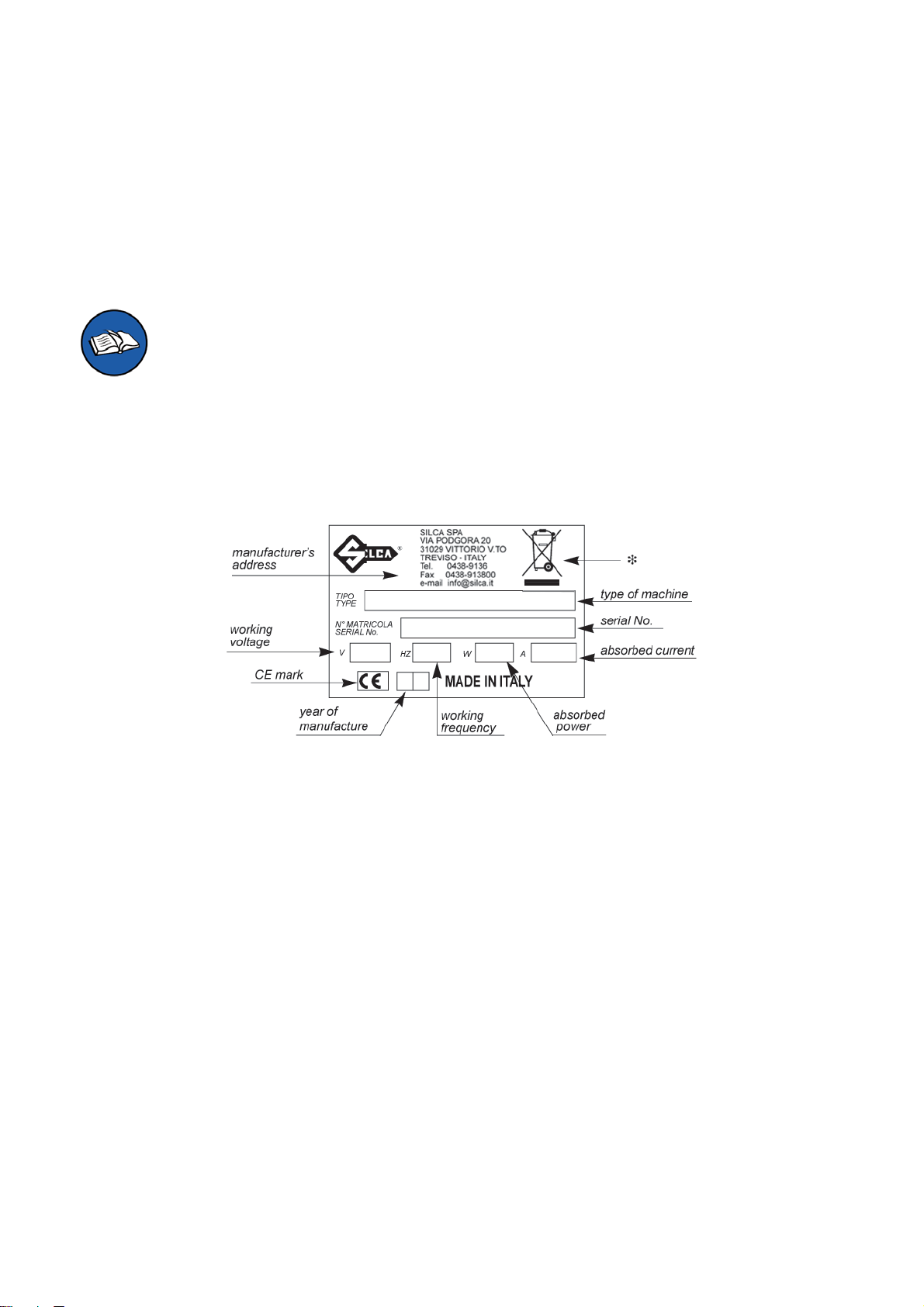
Manufacturer’s ID
FUTURA PRO has an ID plate located on the back of the machine, showing the serial number.
Fig. 1
(*) see chap. 8 DISPOSAL.
How to apply for after-sales service
Silca provides purchasers of FUTURA PRO with After-Sales Service.
For the total safety of the operator and machine, any operation not described in the manual must be carried out
by the manufacturer or in the special Service Centers recommended by Silca.
At the end of the manual there is a list of manufacturers’ and authorized Service Centre addresses; if the manual
was downloaded is necessary visit the website to see the contacts (www.silca.biz).
The warranty card attached to the machine covers free repairs or replacement of faulty parts for 24 months from
the date of purchase*. All operations must be agreed by the user with Silca or the Service Center.
* Damage caused by negligence or wrong use of the machine by the user will null the warranty.
Copyright Silca 2018
1
Operating manual FUTURA PRO
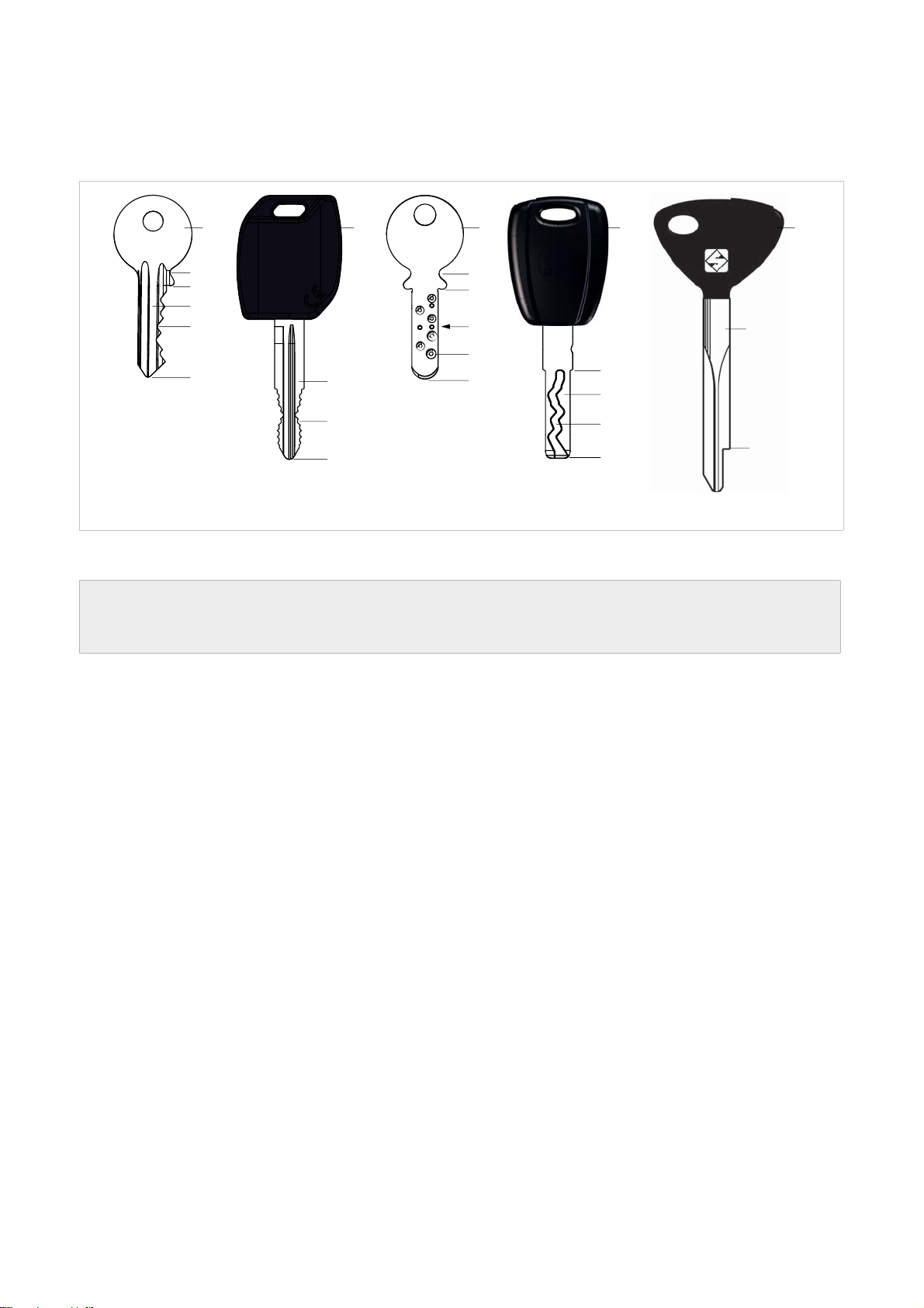
TERMINOLOGY
For those inexperienced in the subject of keys and key cutting, below is an illustration of the most frequently used
terms:
1) Head
2) Neck
3) Shoulder stop
1
2
3
4
7
5
1 1 1
2
3
6
8
4
7
5
5
1
10
3
4
9
5
3
Fig. 2
4) Blade (stem)
5) Tip
6) Back
7) STANDARD cutting
8) DIMPLE cutting
9) TRACK cutting
10) Stem
ATTENTION: anodised aluminium dimple/laser keys, plastic keys or any other key without electrical
conductivity CANNOT BE decoded! For these types of keys digit the cuts directly or enter the indirect
code if the SSN in use allows it.
2
Copyright Silca 2018
Operating manual FUTURA PRO
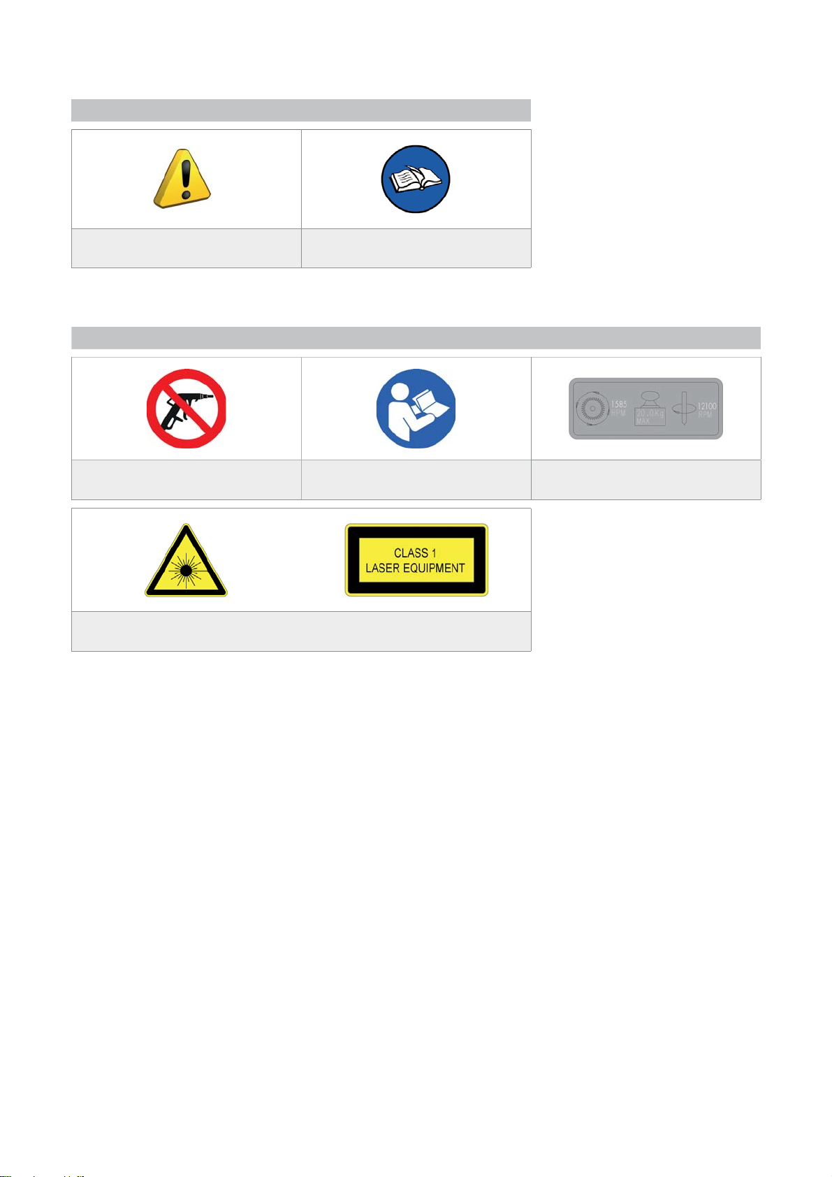
GRAPHICS IN THE MANUAL
Pay attention
Obligation to read
the manual
GRAPHICS ON THE FUTURA PRO KEY-CUTTING MACHINE
Do not clean with
compressed air
Laser warning labels
Obligation to read
the manual
Adhesive label
Mass - RPM
Copyright Silca 2018
3

Operating manual FUTURA PRO
GENERAL WARNINGS
FUTURA PRO is designed to the principles of European Standards (CE).
Right from the design stage solutions have been adopted to eliminate hazards for the operator in all the stages
of use: handling, regulation, use and maintenance.
The materials used in manufacture and the components employed in using FUTURA PRO are not dangerous and
ensure that the machine complies to current standards.
Silca S.p.A. has also experimented and applied numerous technical solutions that allow the key-cutting machine
to optimize the quality of the cut keys.
To guarantee maintaining these results over time, please follow the instructions below:
• Observe the procedures described in this manual;
• Always use Original Silca Tools as they are designed to make the best of FUTURA PRO and
provide quality key-cutting;
• Use Silca/Ilco key blanks, made with top quality materials;
• Have the key-cutting machine checked periodically by an authorized Silca After-Sales Service
Center (list at the end of this manual);
• Always use Silca Original Spare Parts. Beware of imitations!
NORMAL USE
FUTURA PRO is a key-cutting machine and must be installed and used according to the rules and specifi cations
established by the manufacturer.
The FUTURA PRO key-cutting machine is designed for use on business or industrial premises (e.g. hardware
shops, key cutting centers, etc...).
Any other use different from that indicated in this manual will cause the forfeiture of all customers’ rights to make
claims on Silca S.p.A. and may be an unknown source of hazard for the operator or third parties.
A TTENTION: Negligent use or failure by the operator to observe the instructions in this manual
are not covered by the warranty and the manufacturer declines any responsibility in such
cases.
ATTENTION: Anodised aluminium keys, plastic keys or any other key without electrical
conductivity CANNOT BE decoded!
RESIDUAL RISKS
No further risks will arise when properly using the FUTURA PRO machine.
SAFETY REGULATIONS
• Always disconnect the machine when it is not in use or when performing maintenance
operations.
• Check the electrical wiring periodically; replace any wires that show signs of wear.
• Always work with dry hands free of grease or oil.
• Never tug on the electricity supply lead and make sure it is not in contact with oil or other
liquids, sharp objects or heat. Never remove the grounding pin from the plug. Check that the
ground wire is connected properly.
• Do not use the machine in dangerous environments (wet or damp).
• All visitors, especially children, must stay at a safe distance from the machine and must
never come into contact with the electric wiring.
4
Copyright Silca 2018
Operating manual FUTURA PRO
1 MACHINE DESCRIPTION
FUTURA PRO is an electronic machine operating on 3 axes with controlled movement.
Accurately studied, it adds a high degree of cutting precision to operating speed and ease of use.
FUTURA PRO operates only when connected to a TABLET containing a Silca program.
It uses a laser reader to read and/or codify fl at keys with standard cuts.
It uses a tracer to decode keys with dimple and/or track cuts.
It can cut keys (in ferrous materials in general, brass, silver nickel, etc.) having:
• Standard cuts
• Dimple cuts
• Track cuts
• Special cuts (e.g. Ford Tibbe - with optional accessory)
• Cuts on tubular keys (with optional accessory)
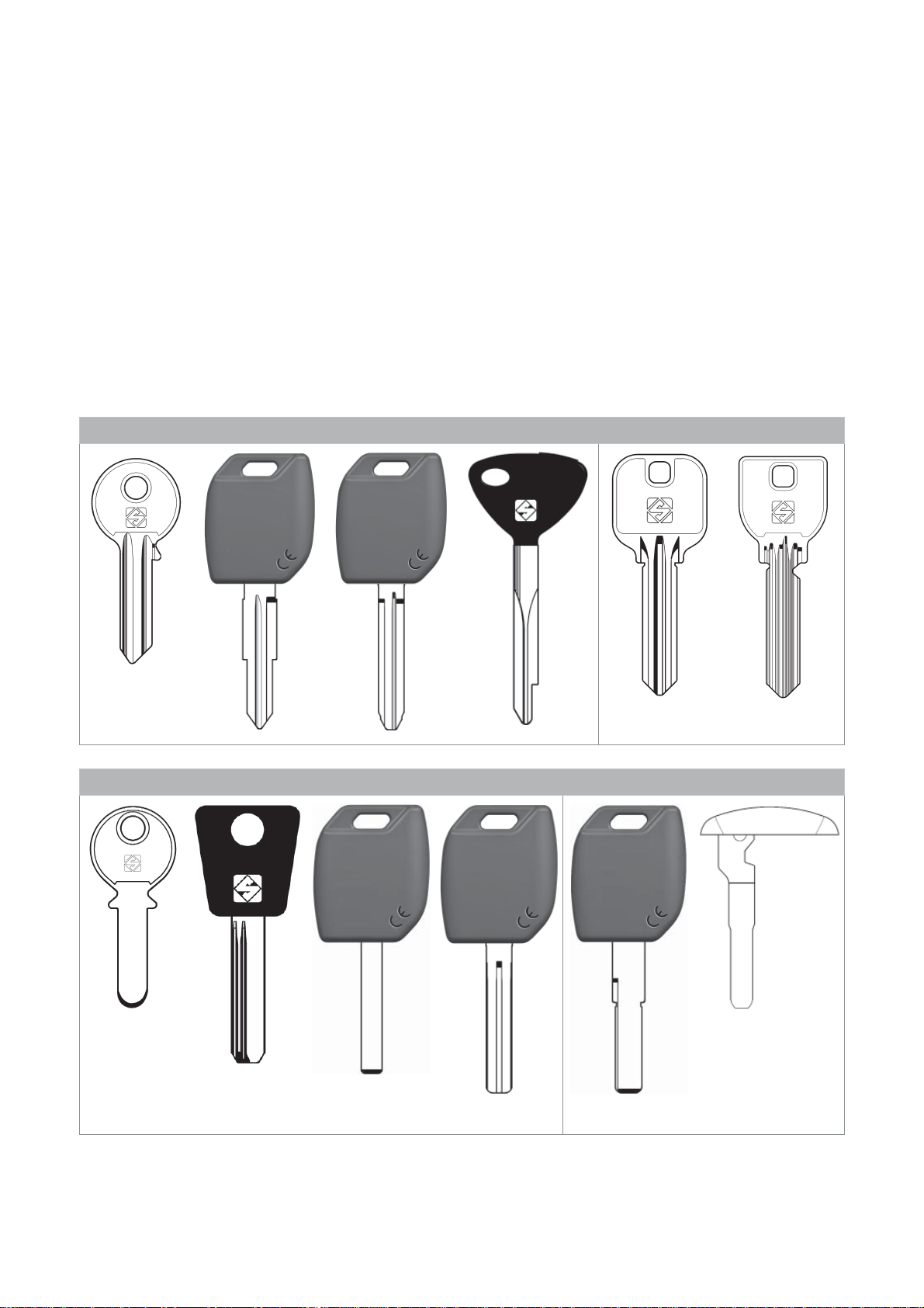
FUTURA PRO is used to cut the following types of keys:
Keys with STANDARD CUTS
STANDARD on
Futura PRO JAPAN
Fig. 3
Keys with DIMPLE and/or TRACK CUTS
STANDARD on Futura PRO NA
and Futura PRO Automotive
Fig. 4
ATTENTION: Anodised aluminium keys, plastic keys or any other key without electrical conductivity
CANNOT BE decoded!
Copyright Silca 2018
5
Operating manual FUTURA PRO
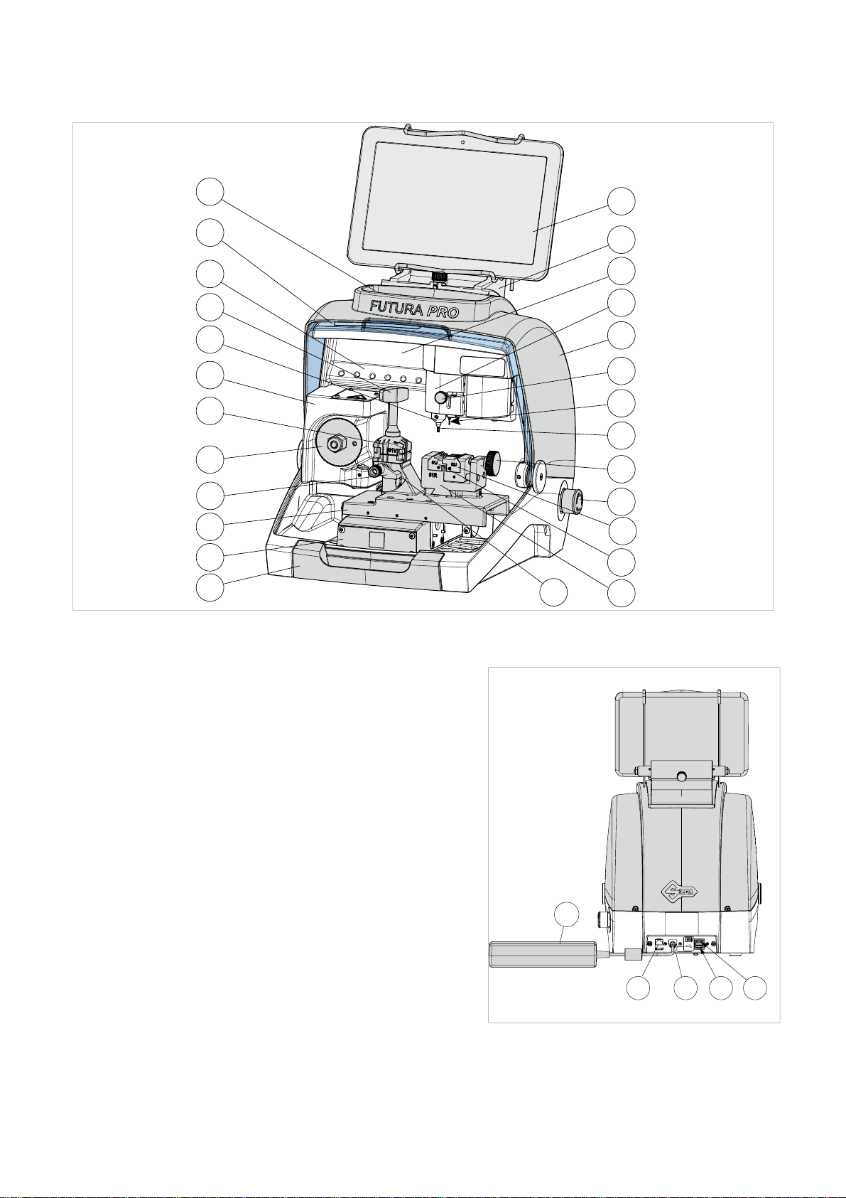
1.1 MAIN OPERATING PARTS
L
C
Z
M1
G1
H
M
F
B
A
D
U
E
J1
J
G
P1
I
S
T
K
Fig. 5
A
- Tablet stand
B
- Tablet
C
- Safety shield
D
- Lamp
E
- Cover
F
- Prismatic cutter (Standard cuts)
G
- Cutter (Dimple/Track cuts)
G1
- Cutter shaft (Dimple/Track cuts)
H
- Optic reader
I
- Gauge
I2
- Gauge sensor
J
- Tracer 01T
J1
- Tracer movement lever
L
- Tool compartment
K
- Swarf collection tray
M
- Clamp 01V (Standard cuts) - Clamp 01J (Futura PRO JAPAN version)
M1
- Clamp knob (01V)
P
- Clamp 01R (Dimple/Track cuts)
P1
- Clamp knob (01R )
Q1
- Left-hand jaw
Q2
- Right-hand jaw
R
- ON/Emergency push button
S
- X axis carriage
T
- Y axis carriage
U
- Z axis carriage
V
- Ethernet port
W
- Power pack
W1
- Power pack connector
Y
- USB port for Tablet charge
Y1
- USB port standard
Z
- Tool holder
R
Q2
Q1
I2
W
P
Fig. 6
Y
V
W1
Y1
6
Copyright Silca 2018
Operating manual FUTURA PRO
1.2 SAFETY
FUTURA PRO is entirely built in compliance to the Machine Directives. The operations for which it has been
designed are easily carried out with no risk to the operator.
The adoption of general safety precautions and observation of the instructions provided by the manufacturer in
this manual eliminate all human error, unless deliberate.
FUTURA PRO is designed with features which make it completely safe.
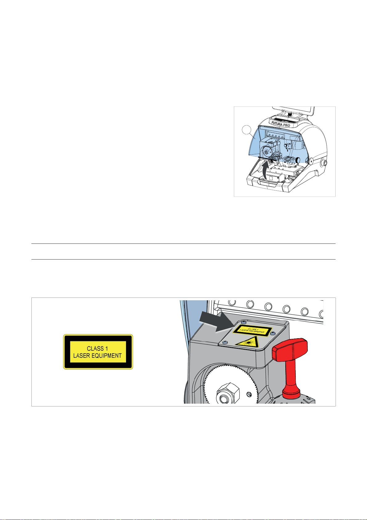
• Safety shield
The protective shield is designed to cover the working parts as completely
as possible, ensuring operator safety.
The shield (C) must be raised in order to fi t keys for cutting or carry out
other operations (Fig. 7).
C
Raising the shield by means of a microswitch will deactivate the operating
and movement functions, including the cutter, and failed shield closing will
be notifi ed with a special message on the tablet.
To re-activate the work cycle, lower the shield and follow the instructions
on the tablet.
Fig. 7
• Emergency stop
Use the red emergency button (R) (Fig. 5), located on the right-hand side of the machine to stop the machine
immediately in the event of serious malfunctioning or a hazard for the operator.
When the cause of the emergency has been eliminated, turn the button 45° clockwise to deactivate it.
NOTE: the operator is responsible for keeping the area around the button clear so that it can be
reached as quickly as possible.
• Laser warning
Regulations require that warning label (supplied - chap.1.4) in the language to be used be attached to the optical
reader, as shown in Fig. 8.
Fig. 8
Copyright Silca 2018
7

Operating manual FUTURA PRO
1.3 TECHNICAL DATA
Electricity supply: Machine: 24V d.c. - 5,5 Amp. - 130W
Power pack: 90/264V a.c. - 50/60Hz - 220W - MEANWELL
GS220A24-R7B
Cutter motor (Standard cuts): 24V d.c.
Cutter motor (Dimple/Track cuts): 24V d.c.
Prismatic cutter (Standard cuts): in HSS super rapid steel, coated
Cutter (Dimple cuts): in HSS Super Rapid steel
Cutter (Track cuts): carbide, coated
Tool speed: prismatic cutter (Standard cuts): 1585 rpm
cutter (Dimple/Track cuts): 12100 rpm
Movement: on 3 axes (with special bushes) driven by step motors (on
rectifi ed roller guides)
Clamp 01V :
(for standard cuts)
removable, with 4 universal sides for holding fl at keys, vehicle
keys and cruciform keys
Clamp 01VJ (Futura PRO JAPAN) removable, with 4 universal sides for holding fl at keys, MIWA
fl at keys, vehicle keys and cruciform keys
Clamp 01R
removable and provided with interchangeable jaws
(for Dimple/Track cuts)
Runs: X axis: 30 mm Y axis: 50 mm Z axis: 27 mm
Dimensions: width: 318 mm
depth: 413 mm
height with tablet and stand: 522 mm (340 mm without tablet
and stand)
Mass: Kg. 20
Noise level: sound pressure Lp(A) =
-
brass fl at keys: 72.0 dB(A)
-
steel fl at keys: 74.5 dB(A)
-
brass dimple keys: 70.0 dB(A)
-
brass track keys: 74.0 dB(A)
-
steel track keys: 75.0 dB(A)
CLASS 1 LASER READER:
• Maximum radiation with safety lock excluded: 230 μW
• Wave length: 790,6 μm (invisible)
• Classed to: EN 60825-1 2007
8
Copyright Silca 2018
Operating manual FUTURA PRO
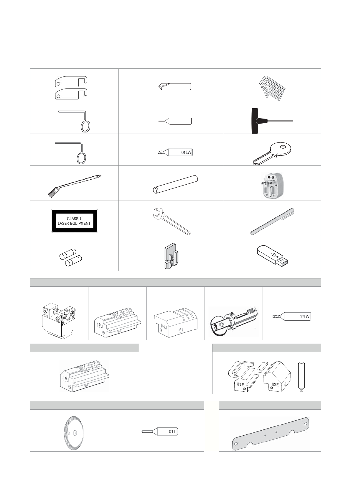
1.4 ACCESSORIES PROVIDED
FUTURA PRO comes with a set of accessories for its operation and maintenance (tools, hex wrenches...) supplied
in a special tool kit comprising:
stop bar cutter 01D Allen keys set 1,5 ÷ 5 mm
01D
ø 1,7 mm steel pin tracer point 02T “T” allen key 2,5 mm
02T
ø 1,2 mm steel pin fresa 01LW template Z3 (regulating key)
slanted brush cutter release rod universal adapter
laser warning label 19 mm spanner stylus touch pen
fuses 4 Amp.- delayed tip stop (Stop 4) USB pen (FAT32 format)
Futura PRO AUTOMOTIVE
03R clamp
(D743276ZB)
4
3
2
1
4
3
2
1
03R
19J jaw
(D744023ZB)
04J jaw
(D743256ZB)
adapter B6
(D708040ZB)
cutter 02LW
(D747839ZB)
Futura PRO NA Futura PRO ENGRAVING
19J jaw (D744023ZB) Engraving kit
3
18DW
Cutters and tracers on machine Separately
cutter 01F tracer point 01T fi xing bracket:
Copyright Silca 2018
9
Operating manual FUTURA PRO
2 HANDLING
The FUTURA PRO key-cutting machine is easy to handle and there are no special hazards involved in moving it.
The packed machine can by carried manually by one person.
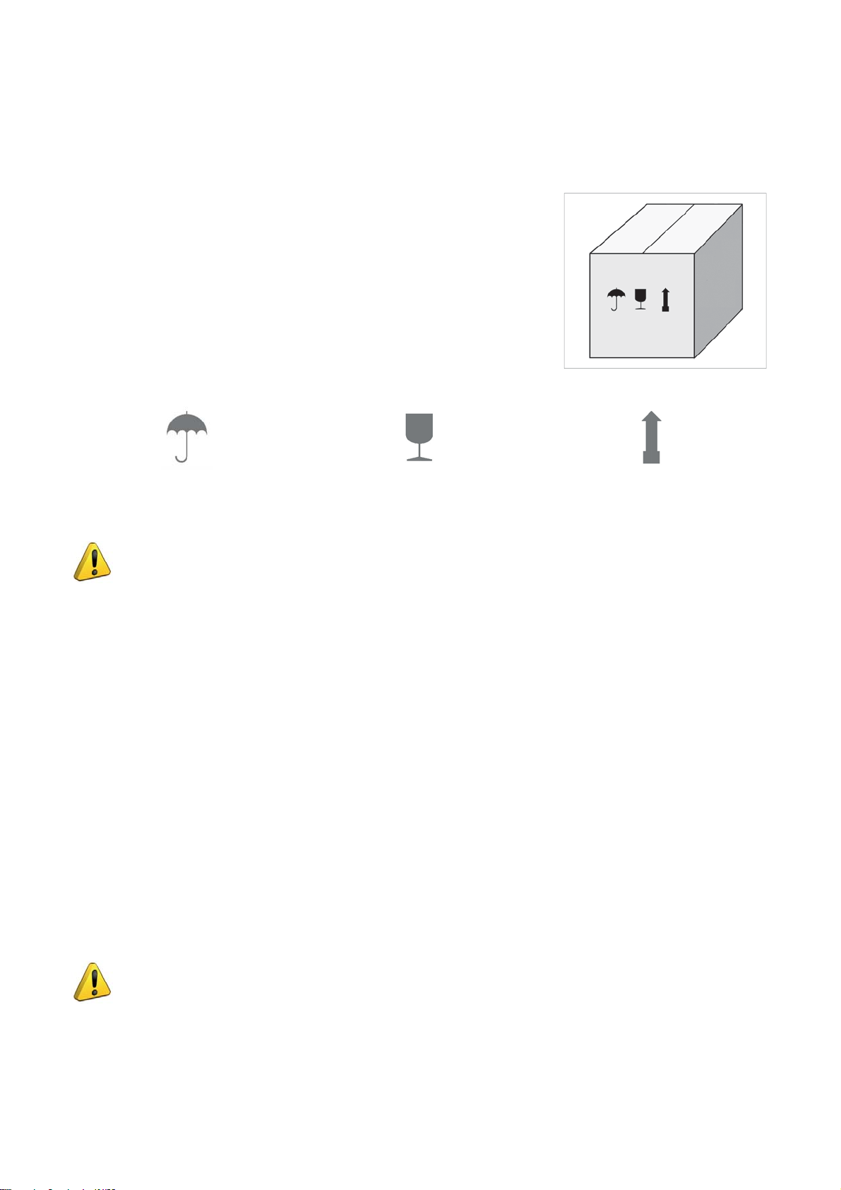
2.1 PACKING
The packing for the FUTURA PRO key-cutting machine ensures safe handling
of the machine and all its components.
Packing comprises expanded plastic material wrapped around the machine.
The robust cardboard box in which it is placed and the nylon wrapping protect
the machine even when stored for a long period.
Fig. 9
Keep dry Handle with care Up
The symbols on the outside of the cardboard box give indications for transport.
ATTENTION: keep the complete packing for future machine transfers.
2.2 UNPACKING
To remove the machine from its packing:
1) Cut the strapping with scissors and remove.
2) Open the box carefully without damaging it.
3) Free the machine from the protective shells.
4) Check the contents of the packing, comprised of:
-
FUTURA PRO key-cutting machine
-
documentation comprising: user’s manual, spare parts sheet, specialist guide and warranty
-
tablet
-
tablet stand
-
power lead
-
power pack
-
tool kit
-
fi xing bracket
2.3 HANDLING THE MACHINE
Once removed from its packing place FUTURA PRO directly on the work bench; one person can easily perform
this operation.
ATTENTION: lift the machine by holding onto the base. Never lift the machine by gripping the
clamps, levers or other parts.
10
Copyright Silca 2018
Operating manual FUTURA PRO
3 MACHINE INSTALLATION AND PREPARATION
Installation is the customer’s task and does not require any special skills.
The key-cutting machine is supplied ready for use and does not need calibration except for the tools to be used
and any additional jaws that are included with the machine; however, the operator is required to make certain
checks and prepare the machine for use.
NOTE: the machine is shipped with a steel rod installed in the cutter shaft to prevent the allen screw
from backing out during transit. REMOVE THE ROD AND INSTALL THE PROPER CUTTER PRIOR TO
ATTEMPTING TO CUT A KEY!
3.1 CHECKING FOR DAMAGE
FUTURA PRO is a solid compact machine and will not break if handling, unpacking and installation are carried out
to the instructions in this manual. However, it is good practice to check that the machine has not been damaged.
3.2 ENVIRONMENTAL CONDITIONS
To make the most of the key-cutting machine, bear in mind the following environmental parameters: it is advisable
for the area to be dry with good air circulation.
The optimum environmental conditions for machine operation are:
- temperature 10° C to 40°C;
- relative humidity: approx 60%.
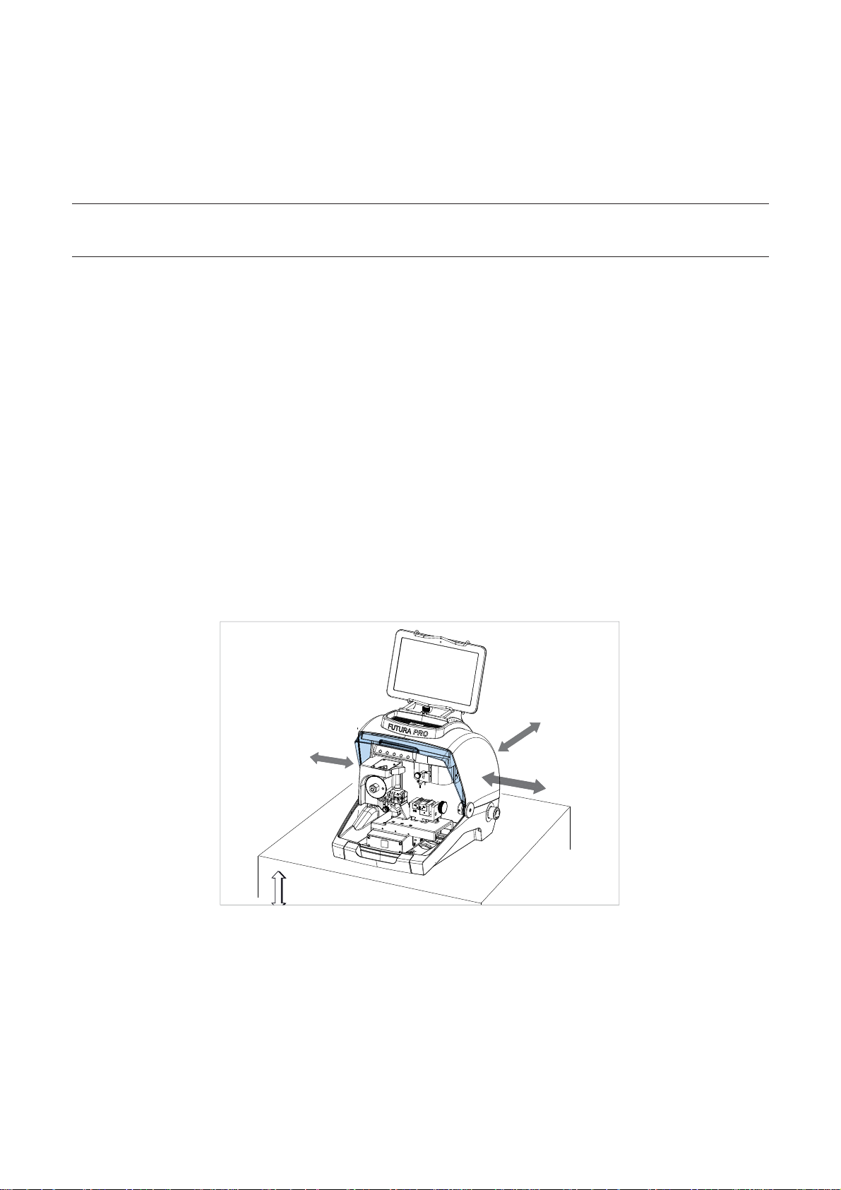
3.3 POSITIONING
1) Place the key-cutting machine on a solid horizontal work bench suitable for the weight of the machine (20
Kg). The work bench should be approximately 100-120 cm high to facilitate access to the working parts. We
recommend leaving at least 30 cm clearance behind and around the machine to ensure good ventilation and
facilitate handling (Fig. 10).
2) Make sure machine voltage is suitable for the mains supply and that the latter is earthed with a differential switch.
3) Connect the power lead (power pack) to the machine (chap.3.4.2).
30 cm
100/120 cm
30 cm
30 cm
Fig. 10
Copyright Silca 2018
11
Operating manual FUTURA PRO
3.4 SEPARATE PARTS
The machine packing also contains the following components, separately packed:
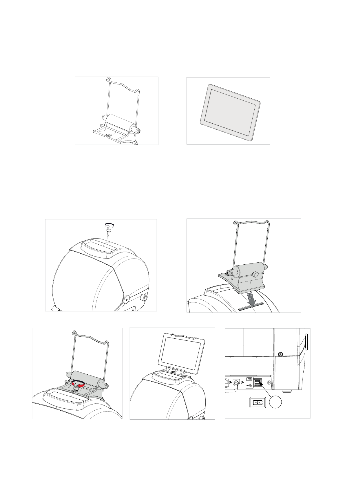
3.4.1 Tablet stand and tablet
Fig. 11 Fig. 12
These items are separate from the machine and must be unpacked and installed by the operator in the way
described below:
1) Remove the 2 items from their packing.
2) Loosen the knob on top of the machine cover (Fig. 13).
3) Install the tablet stand so that the special profi le fi ts into the slot on the machine cover (Fig. 14).
4) Screw down and tighten the knob to secure the tablet stand to the cover (Fig. 15).
5) Fit the tablet into its stand (Fig. 16).
Fig. 13 Fig. 14
Y
Fig. 15 Fig. 16 Fig. 17
6) Connect the tablet USB/Micro USB cable to the USB tablet port (Y) located on the back of Futura PRO.
12
Copyright Silca 2018
 Loading...