

Silca FUTURA PRO, FUTURA PRO NA, FUTURA PRO ENGRAVING, FUTURA PRO JAPAN, FUTURA PRO AUTO Operating Manual
Page 1
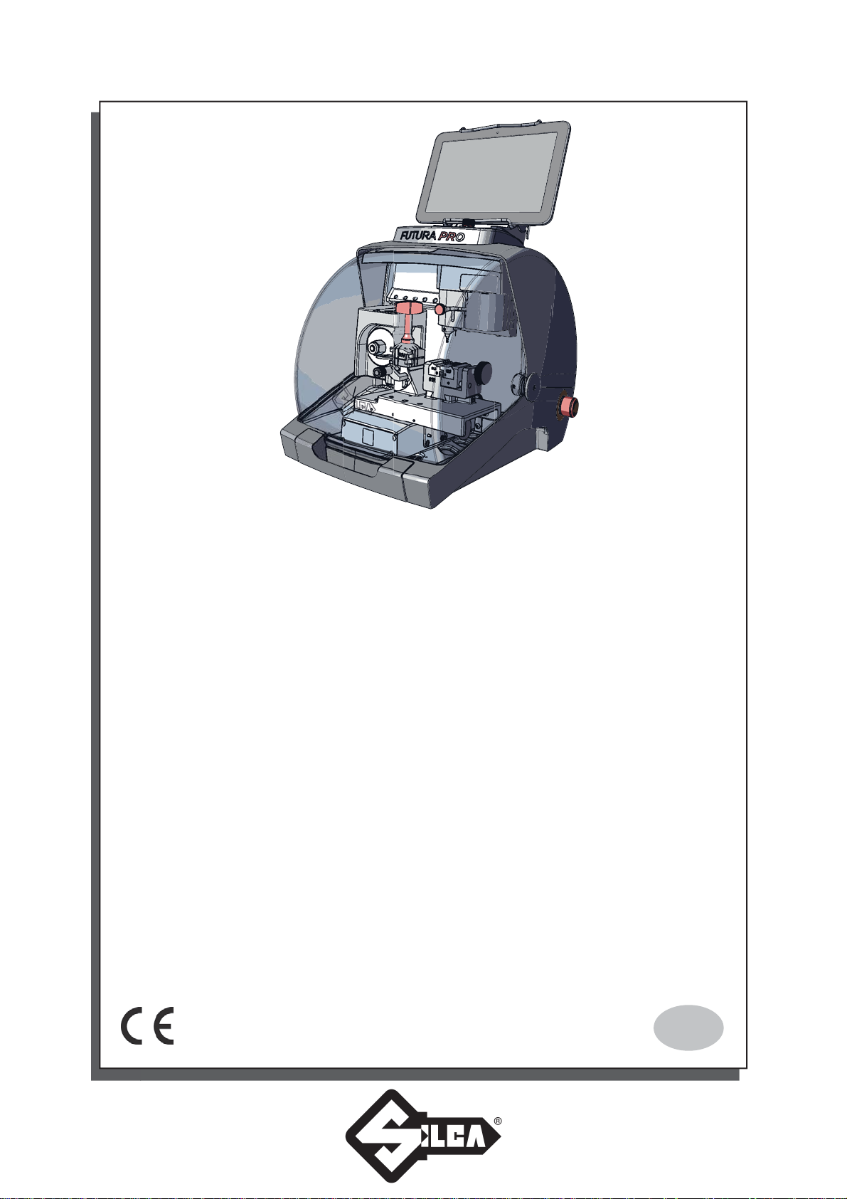
FUTURA
PRO
FUTURA
FUTURA
FUTURA
FUTURA
Operating Manual
Original Instructions
PRO
PRO
PRO
PRO
D446440XA
vers. 3.0
NA
JAPAN
Auto
ENGRAVING
EN
Page 2

(c) 2016 SILCA S.p.A. - Vittorio Veneto
This manual has been drawn up by SILCA S.p.A.
All rights reserved. No part of this publication can be reproduced or circulated by any means whatsoever (photocopies, microfi lm or other)
without the consent of SILCA S.p.A.
Edition: January 2018
Printed at Vittorio Veneto
Da SILCA S.p.A.
Via Podgora, 20 (Z.I.)
31029 VITTORIO VENETO (TV) - Italy
The Manufacturer declines any responsibility for possible inaccuracies in this document due to printing or transcription errors. The Manufacturer
reserves the rights to alter the information without prior notice, except when they affect safety. This document or any of its parts cannot be copied,
altered or reproduced without written authorization from the Manufacturer. Keep the manual and look after it for the entire life cycle of the machine.
The information has been drawn up by the manufacturer in his own language (Italian) to provide users with the necessary indications to use the keycutting machine independently, economically and safely.
IMPORTANT NOTE: in compliance with current regulations relating to industrial property, we hereby state that the trade-marks or trade names
mentioned in our documentation are the exclusive property of authorized manufacturers of locks and users.
Said trade-marks or trade names are nominated only for the purposes of information so that any lock for which our keys are made can be rapidly
identifi ed.
Page 3

INDEX
USE OF THE MANUAL .............................................................................................................................................. 1
GENERAL WARNINGS .............................................................................................................................................. 4
1 MACHINE DESCRIPTION ................................................................................................................................. 5
1.1 MAIN OPERATING PARTS ............................................................................................................................... 6
1.2 SAFETY ............................................................................................................................................................ 7
1.3 TECHNICAL DATA ............................................................................................................................................ 8
1.4 ACCESSORIES PROVIDED ............................................................................................................................ 9
2 HANDLING ...................................................................................................................................................... 10
2.1 PACKING ........................................................................................................................................................ 10
2.2 UNPACKING ................................................................................................................................................... 10
2.3 HANDLING THE MACHINE ............................................................................................................................ 10
3 MACHINE INSTALLATION AND PREPARATION .............................................................................................11
3.1 CHECKING FOR DAMAGE .............................................................................................................................11
3.2 ENVIRONMENTAL CONDITIONS ...................................................................................................................11
3.3 POSITIONING ..................................................................................................................................................11
3.4 SEPARATE PARTS ......................................................................................................................................... 12
3.4.1 TABLET STAND AND TABLET ...................................................................................................................... 12
3.4.2 POWER PACK AND LEAD ............................................................................................................................ 13
3.4.3 FIXING BRACKET ......................................................................................................................................... 13
3.5 WORK STATION DESCRIPTION .................................................................................................................. 14
4 TABLET REGULATION AND USE ................................................................................................................... 15
4.1 CHOICE OF LANGUAGE ............................................................................................................................... 15
5 CLAMPS ......................................................................................................................................................... 16
5.1 CLAMPS FOR FLAT KEYS WITH STANDARD CUTS ................................................................................... 16
5.1.1 USE OF THE SHOULDER GAUGE .............................................................................................................. 18
5.1.2 STOP POSITIONS (KEY STOP) ................................................................................................................... 19
5.1.3 USE OF PINS - CLAMP 01V / 01VJ .............................................................................................................. 20
5.1.4 CUTTING CRUCIFORM KEYS (WITH 3 FINS) ............................................................................................ 21
5.1.5 REMOVING/FITTING THE CLAMP 01V / 01VJ ............................................................................................ 22
5.2 LAMP FOR DIMPLE AND TRACK KEYS - 01R ............................................................................................. 23
5.2.1 DIMPLE KEYS ............................................................................................................................................... 23
5.2.2 TRACK TYPE KEYS ...................................................................................................................................... 24
5.2.3 TRACK TYPE KEYS (FUTURA PRO NA - FUTURA PRO AUTOMOTIVE) .................................................. 24
5.3 REMOVING / FITTING CLAMP 01R .............................................................................................................. 25
5.4 REMOVING/FITTING THE JAWS ON CLAMP 01R ...................................................................................... 25
5.5 USING TRACER 01T ...................................................................................................................................... 26
5.6 TRACER 02T .................................................................................................................................................. 26
5.7 ENGRAVING ................................................................................................................................................... 27
6 CLEANING ....................................................................................................................................................... 30
7 MAINTENANCE ............................................................................................................................................... 31
7.1 OPERATIONS ................................................................................................................................................. 31
Page 4

7.2 ACCESS TO REAR COMPARTMENT ............................................................................................................ 31
7.3 PRISMATIC CUTTER REPLACEMENT ........................................................................................................ 32
7.4 CYLINDRICAL CUTTER AND/OR TRACER POINT REPLACEMENT .......................................................... 33
7.5 TRACER 01T REPLACEMENT ...................................................................................................................... 33
7.6 CHECKING AND REPLACING FUSE ............................................................................................................ 34
7.7 BATTERY REPLACEMENT ............................................................................................................................ 35
8 DISPOSAL ....................................................................................................................................................... 36
9 ASSISTANCE................................................................................................................................................... 37
9.1 HOW TO REQUEST SERVICE ...................................................................................................................... 37
10 SOFTWARE OPERATING GUIDE ................................................................................................................ 38
11 ELECTRICAL DIAGRAMS .............................................................................................................................. 39
CE DECLARATION
Page 5
Operating manual
USE OF THE MANUAL
This manual has been drawn up by the Manufacturer and is an integral part of the machine literature.
The manual gives information that is obligatory for the operator to know and which makes it possible to use the
machine safely.
User’s Manual
This user’s manual is provided because it is essential for proper use and maintenance of the machine.
The manual must be kept carefully throughout the life of the machine, including the decommissioning stage. Keep
in a dry place close to the machine where it is always to hand for the operator.
IT IS OBLIGATORY to read the manual carefully before using the machine.
Readers’ characteristics
This manual must be read and its contents acquired by those who will use it.
Manufacturer’s ID
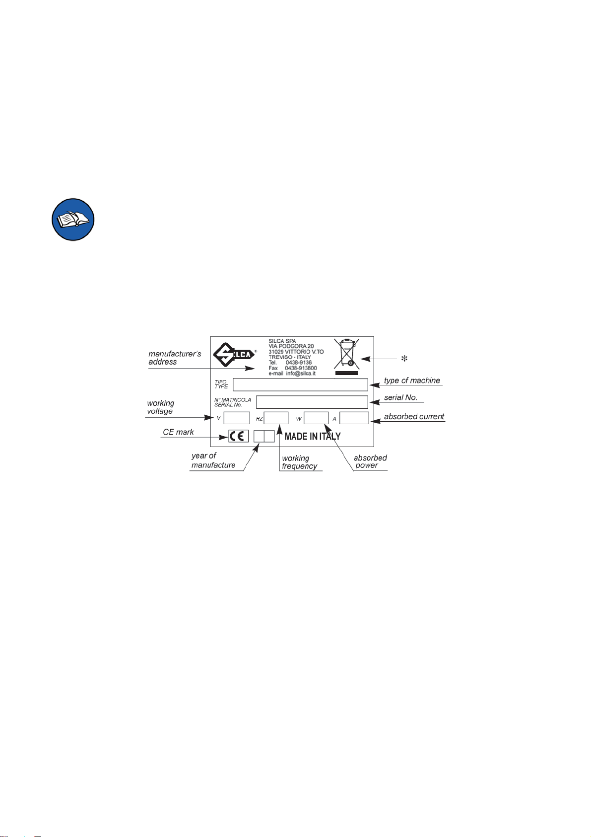
FUTURA PRO has an ID plate located on the back of the machine, showing the serial number.
Fig. 1
(*) see chap. 8 DISPOSAL.
How to apply for after-sales service
Silca provides purchasers of FUTURA PRO with After-Sales Service.
For the total safety of the operator and machine, any operation not described in the manual must be carried out
by the manufacturer or in the special Service Centers recommended by Silca.
At the end of the manual there is a list of manufacturers’ and authorized Service Centre addresses; if the manual
was downloaded is necessary visit the website to see the contacts (www.silca.biz).
The warranty card attached to the machine covers free repairs or replacement of faulty parts for 24 months from
the date of purchase*. All operations must be agreed by the user with Silca or the Service Center.
* Damage caused by negligence or wrong use of the machine by the user will null the warranty.
Copyright Silca 2018
1
Page 6
Operating manual FUTURA PRO
TERMINOLOGY
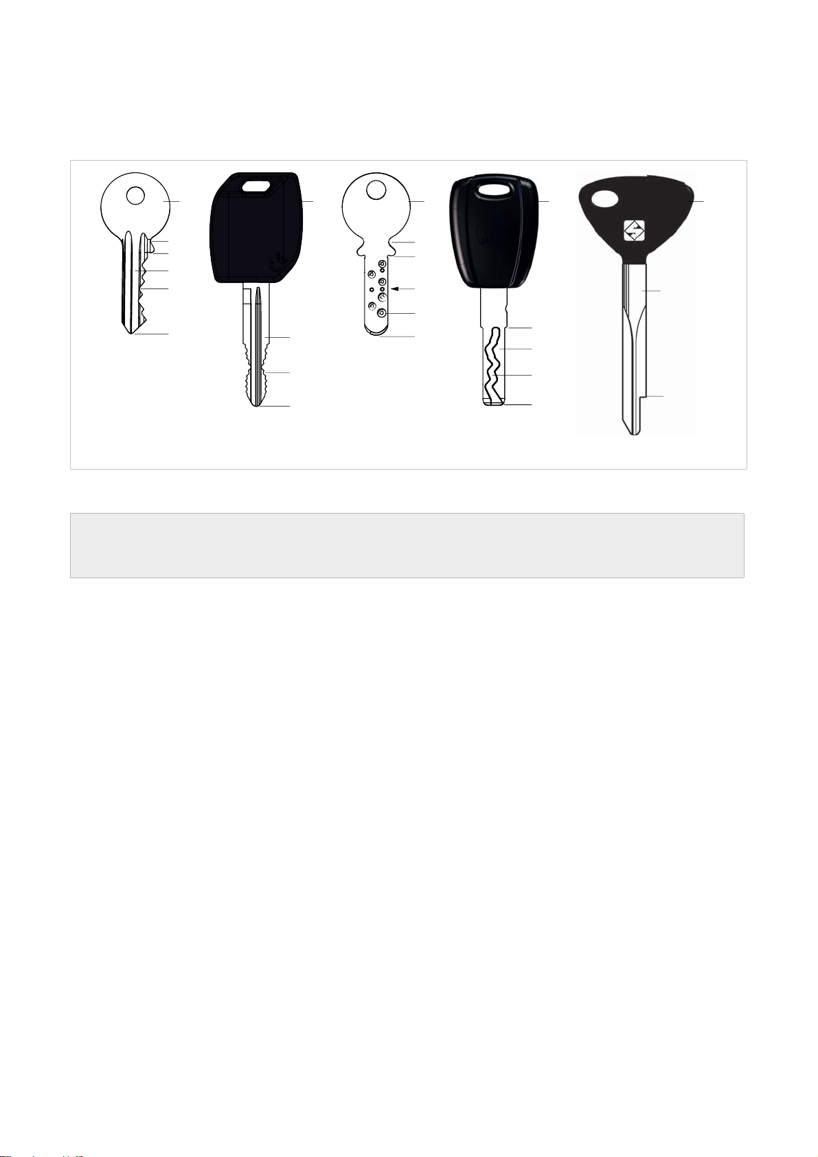
For those inexperienced in the subject of keys and key cutting, below is an illustration of the most frequently used
terms:
1) Head
2) Neck
3) Shoulder stop
1
2
3
4
7
5
1 1 1
2
3
6
8
4
7
5
5
1
10
3
4
9
5
3
Fig. 2
4) Blade (stem)
5) Tip
6) Back
7) STANDARD cutting
8) DIMPLE cutting
9) TRACK cutting
10) Stem
ATTENTION: anodised aluminium dimple/laser keys, plastic keys or any other key without electrical
conductivity CANNOT BE decoded! For these types of keys digit the cuts directly or enter the indirect
code if the SSN in use allows it.
2
Copyright Silca 2018
Page 7
Operating manual FUTURA PRO
GRAPHICS IN THE MANUAL
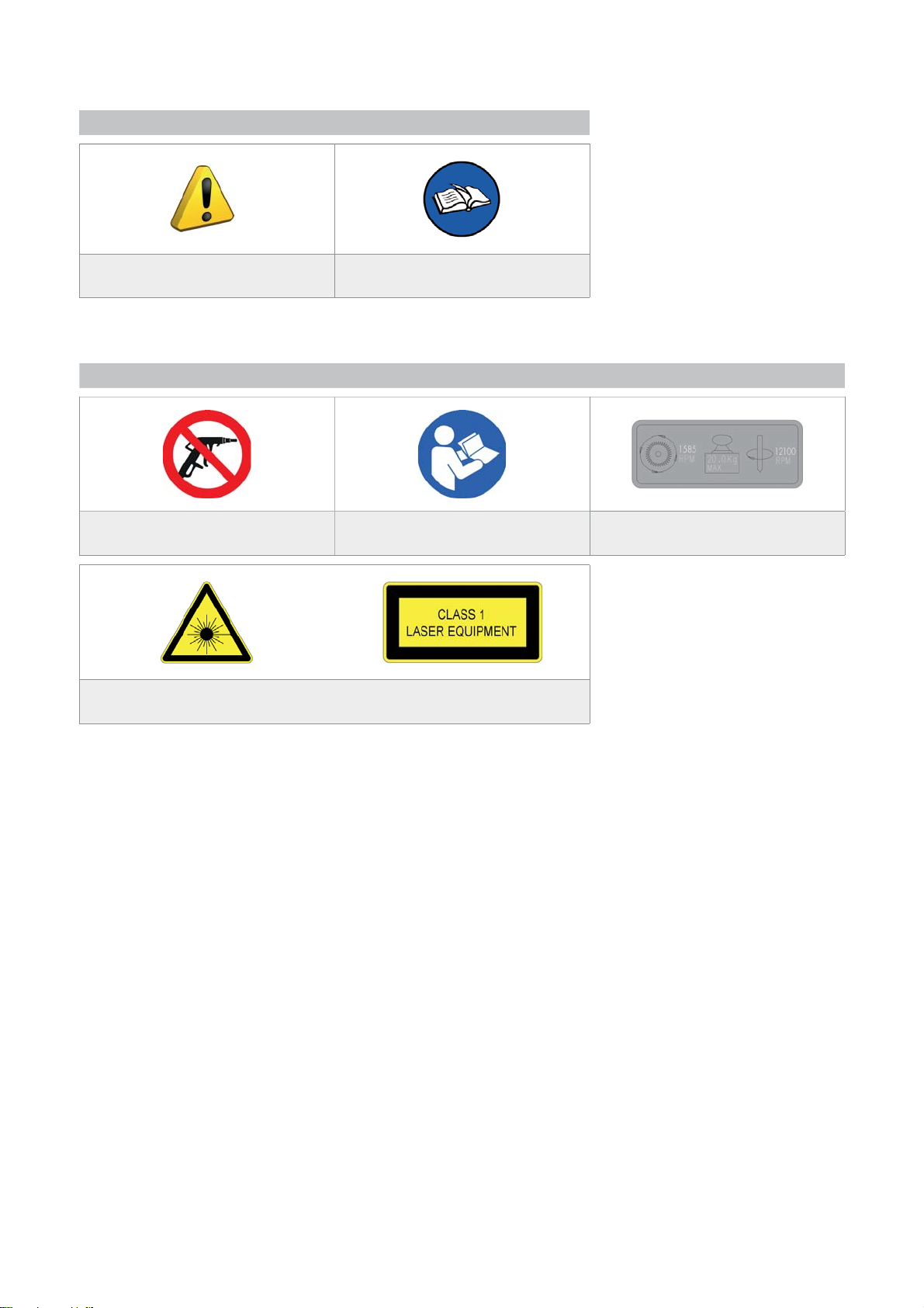
Pay attention
Obligation to read
the manual
GRAPHICS ON THE FUTURA PRO KEY-CUTTING MACHINE
Do not clean with
compressed air
Laser warning labels
Obligation to read
the manual
Adhesive label
Mass - RPM
Copyright Silca 2018
3
Page 8

Operating manual FUTURA PRO
GENERAL WARNINGS
FUTURA PRO is designed to the principles of European Standards (CE).
Right from the design stage solutions have been adopted to eliminate hazards for the operator in all the stages
of use: handling, regulation, use and maintenance.
The materials used in manufacture and the components employed in using FUTURA PRO are not dangerous and
ensure that the machine complies to current standards.
Silca S.p.A. has also experimented and applied numerous technical solutions that allow the key-cutting machine
to optimize the quality of the cut keys.
To guarantee maintaining these results over time, please follow the instructions below:
• Observe the procedures described in this manual;
• Always use Original Silca Tools as they are designed to make the best of FUTURA PRO and
provide quality key-cutting;
• Use Silca/Ilco key blanks, made with top quality materials;
• Have the key-cutting machine checked periodically by an authorized Silca After-Sales Service
Center (list at the end of this manual);
• Always use Silca Original Spare Parts. Beware of imitations!
NORMAL USE
FUTURA PRO is a key-cutting machine and must be installed and used according to the rules and specifi cations
established by the manufacturer.
The FUTURA PRO key-cutting machine is designed for use on business or industrial premises (e.g. hardware
shops, key cutting centers, etc...).
Any other use different from that indicated in this manual will cause the forfeiture of all customers’ rights to make
claims on Silca S.p.A. and may be an unknown source of hazard for the operator or third parties.
A TTENTION: Negligent use or failure by the operator to observe the instructions in this manual
are not covered by the warranty and the manufacturer declines any responsibility in such
cases.
ATTENTION: Anodised aluminium keys, plastic keys or any other key without electrical
conductivity CANNOT BE decoded!
RESIDUAL RISKS
No further risks will arise when properly using the FUTURA PRO machine.
SAFETY REGULATIONS
• Always disconnect the machine when it is not in use or when performing maintenance
operations.
• Check the electrical wiring periodically; replace any wires that show signs of wear.
• Always work with dry hands free of grease or oil.
• Never tug on the electricity supply lead and make sure it is not in contact with oil or other
liquids, sharp objects or heat. Never remove the grounding pin from the plug. Check that the
ground wire is connected properly.
• Do not use the machine in dangerous environments (wet or damp).
• All visitors, especially children, must stay at a safe distance from the machine and must
never come into contact with the electric wiring.
4
Copyright Silca 2018
Page 9
Operating manual FUTURA PRO
1 MACHINE DESCRIPTION
FUTURA PRO is an electronic machine operating on 3 axes with controlled movement.
Accurately studied, it adds a high degree of cutting precision to operating speed and ease of use.
FUTURA PRO operates only when connected to a TABLET containing a Silca program.
It uses a laser reader to read and/or codify fl at keys with standard cuts.
It uses a tracer to decode keys with dimple and/or track cuts.
It can cut keys (in ferrous materials in general, brass, silver nickel, etc.) having:
• Standard cuts
• Dimple cuts
• Track cuts
• Special cuts (e.g. Ford Tibbe - with optional accessory)
• Cuts on tubular keys (with optional accessory)
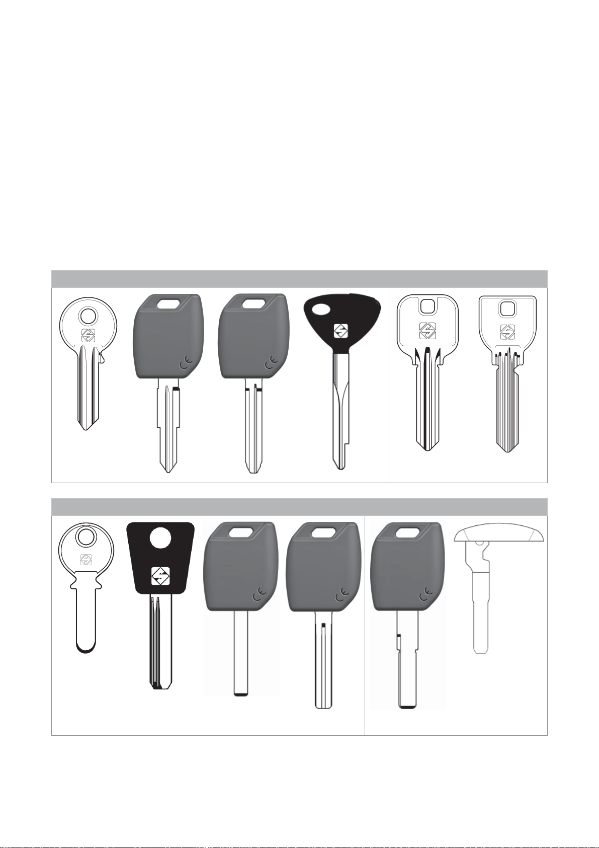
FUTURA PRO is used to cut the following types of keys:
Keys with STANDARD CUTS
STANDARD on
Futura PRO JAPAN
Fig. 3
Keys with DIMPLE and/or TRACK CUTS
STANDARD on Futura PRO NA
and Futura PRO Automotive
Fig. 4
ATTENTION: Anodised aluminium keys, plastic keys or any other key without electrical conductivity
CANNOT BE decoded!
Copyright Silca 2018
5
Page 10
Operating manual FUTURA PRO
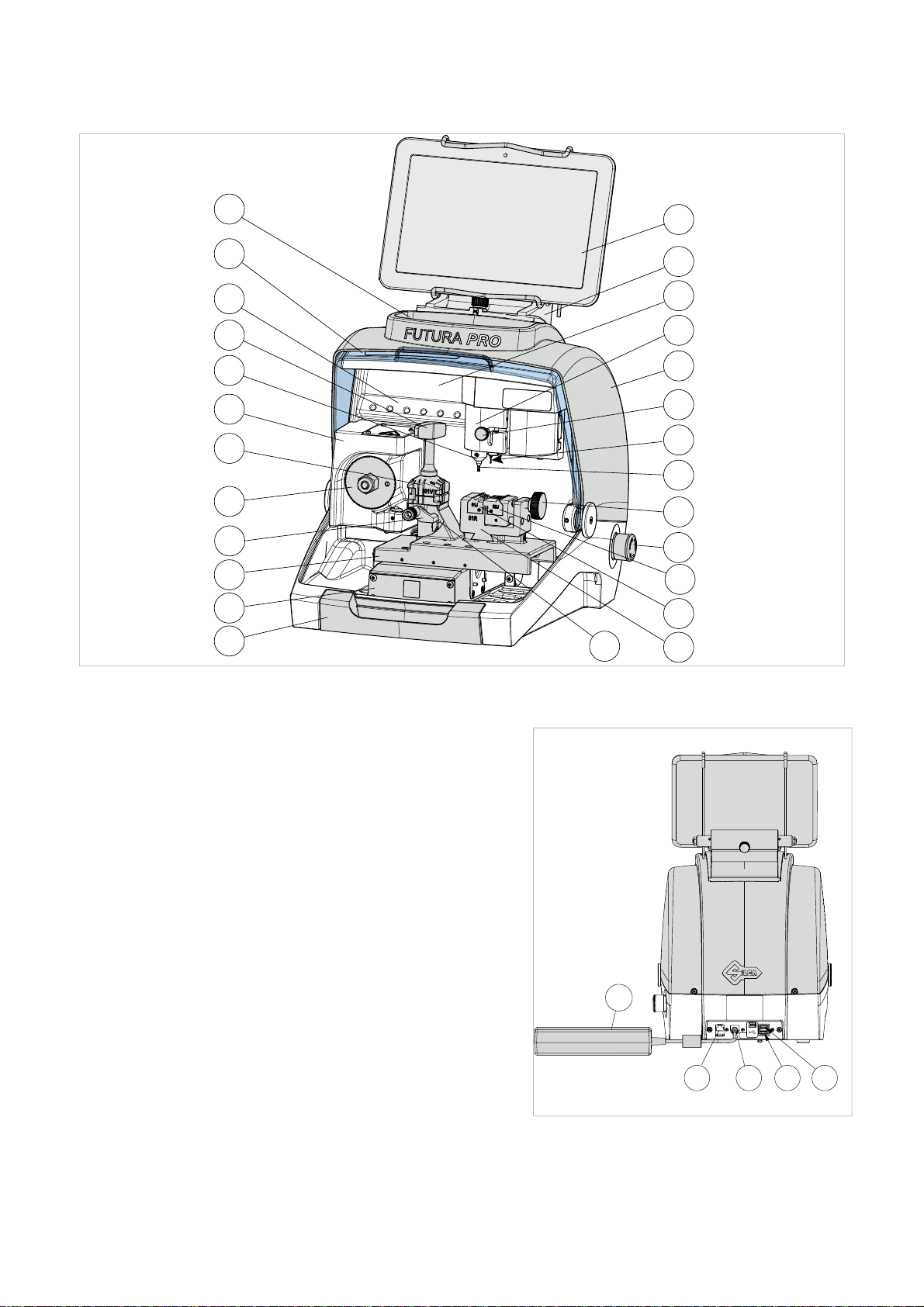
1.1 MAIN OPERATING PARTS
L
C
Z
M1
G1
H
M
F
B
A
D
U
E
J1
J
G
P1
I
S
T
K
Fig. 5
A
- Tablet stand
B
- Tablet
C
- Safety shield
D
- Lamp
E
- Cover
F
- Prismatic cutter (Standard cuts)
G
- Cutter (Dimple/Track cuts)
G1
- Cutter shaft (Dimple/Track cuts)
H
- Optic reader
I
- Gauge
I2
- Gauge sensor
J
- Tracer 01T
J1
- Tracer movement lever
L
- Tool compartment
K
- Swarf collection tray
M
- Clamp 01V (Standard cuts) - Clamp 01J (Futura PRO JAPAN version)
M1
- Clamp knob (01V)
P
- Clamp 01R (Dimple/Track cuts)
P1
- Clamp knob (01R )
Q1
- Left-hand jaw
Q2
- Right-hand jaw
R
- ON/Emergency push button
S
- X axis carriage
T
- Y axis carriage
U
- Z axis carriage
V
- Ethernet port
W
- Power pack
W1
- Power pack connector
Y
- USB port for Tablet charge
Y1
- USB port standard
Z
- Tool holder
R
Q2
Q1
I2
W
P
Fig. 6
Y
V
W1
Y1
6
Copyright Silca 2018
Page 11
Operating manual FUTURA PRO
1.2 SAFETY
FUTURA PRO is entirely built in compliance to the Machine Directives. The operations for which it has been
designed are easily carried out with no risk to the operator.
The adoption of general safety precautions and observation of the instructions provided by the manufacturer in
this manual eliminate all human error, unless deliberate.
FUTURA PRO is designed with features which make it completely safe.
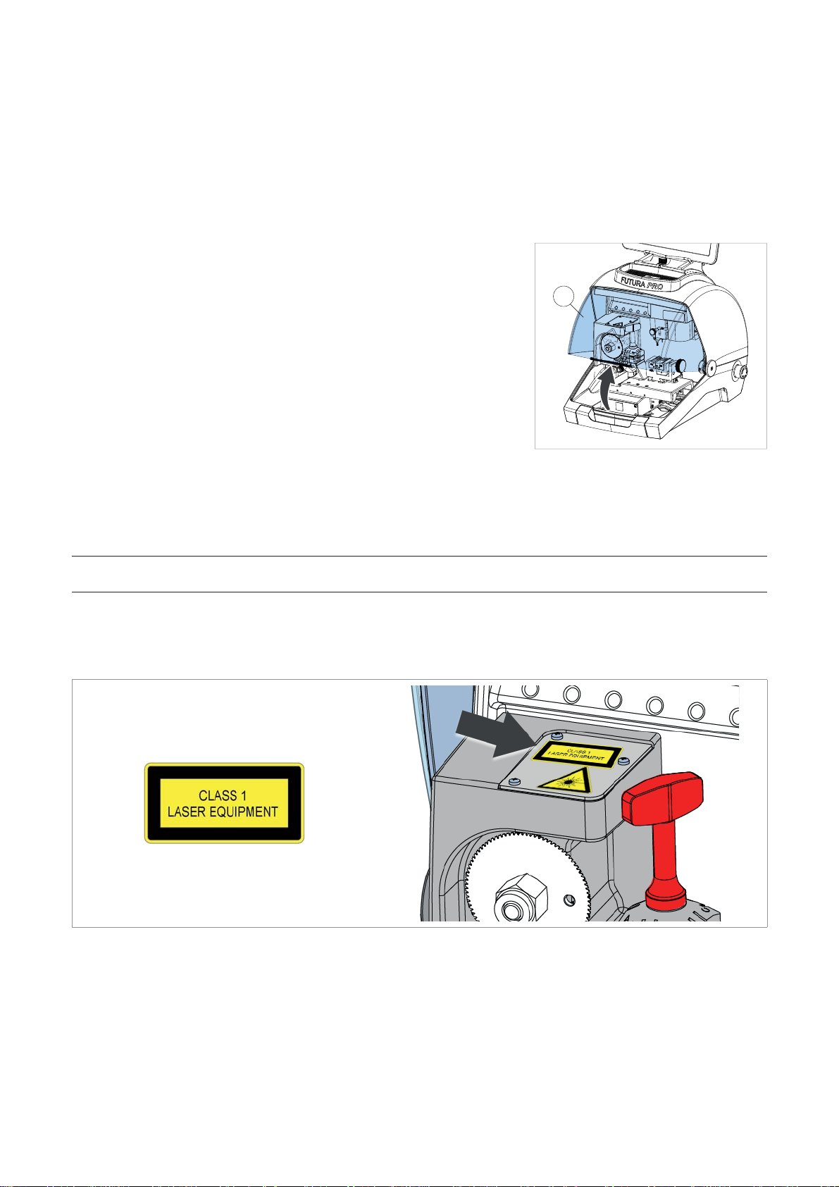
• Safety shield
The protective shield is designed to cover the working parts as completely
as possible, ensuring operator safety.
The shield (C) must be raised in order to fi t keys for cutting or carry out
other operations (Fig. 7).
C
Raising the shield by means of a microswitch will deactivate the operating
and movement functions, including the cutter, and failed shield closing will
be notifi ed with a special message on the tablet.
To re-activate the work cycle, lower the shield and follow the instructions
on the tablet.
Fig. 7
• Emergency stop
Use the red emergency button (R) (Fig. 5), located on the right-hand side of the machine to stop the machine
immediately in the event of serious malfunctioning or a hazard for the operator.
When the cause of the emergency has been eliminated, turn the button 45° clockwise to deactivate it.
NOTE: the operator is responsible for keeping the area around the button clear so that it can be
reached as quickly as possible.
• Laser warning
Regulations require that warning label (supplied - chap.1.4) in the language to be used be attached to the optical
reader, as shown in Fig. 8.
Fig. 8
Copyright Silca 2018
7
Page 12

Operating manual FUTURA PRO
1.3 TECHNICAL DATA
Electricity supply: Machine: 24V d.c. - 5,5 Amp. - 130W
Power pack: 90/264V a.c. - 50/60Hz - 220W - MEANWELL
GS220A24-R7B
Cutter motor (Standard cuts): 24V d.c.
Cutter motor (Dimple/Track cuts): 24V d.c.
Prismatic cutter (Standard cuts): in HSS super rapid steel, coated
Cutter (Dimple cuts): in HSS Super Rapid steel
Cutter (Track cuts): carbide, coated
Tool speed: prismatic cutter (Standard cuts): 1585 rpm
cutter (Dimple/Track cuts): 12100 rpm
Movement: on 3 axes (with special bushes) driven by step motors (on
rectifi ed roller guides)
Clamp 01V :
(for standard cuts)
removable, with 4 universal sides for holding fl at keys, vehicle
keys and cruciform keys
Clamp 01VJ (Futura PRO JAPAN) removable, with 4 universal sides for holding fl at keys, MIWA
fl at keys, vehicle keys and cruciform keys
Clamp 01R
removable and provided with interchangeable jaws
(for Dimple/Track cuts)
Runs: X axis: 30 mm Y axis: 50 mm Z axis: 27 mm
Dimensions: width: 318 mm
depth: 413 mm
height with tablet and stand: 522 mm (340 mm without tablet
and stand)
Mass: Kg. 20
Noise level: sound pressure Lp(A) =
-
brass fl at keys: 72.0 dB(A)
-
steel fl at keys: 74.5 dB(A)
-
brass dimple keys: 70.0 dB(A)
-
brass track keys: 74.0 dB(A)
-
steel track keys: 75.0 dB(A)
CLASS 1 LASER READER:
• Maximum radiation with safety lock excluded: 230 μW
• Wave length: 790,6 μm (invisible)
• Classed to: EN 60825-1 2007
8
Copyright Silca 2018
Page 13
Operating manual FUTURA PRO
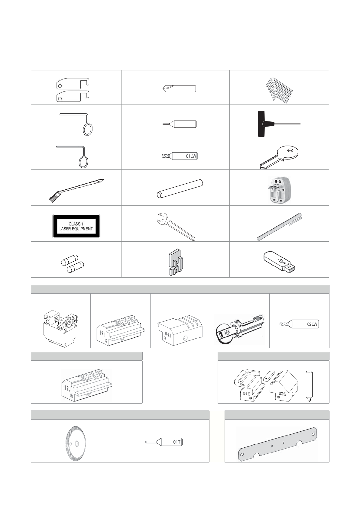
1.4 ACCESSORIES PROVIDED
FUTURA PRO comes with a set of accessories for its operation and maintenance (tools, hex wrenches...) supplied
in a special tool kit comprising:
stop bar cutter 01D Allen keys set 1,5 ÷ 5 mm
01D
ø 1,7 mm steel pin tracer point 02T “T” allen key 2,5 mm
02T
ø 1,2 mm steel pin fresa 01LW template Z3 (regulating key)
slanted brush cutter release rod universal adapter
laser warning label 19 mm spanner stylus touch pen
fuses 4 Amp.- delayed tip stop (Stop 4) USB pen (FAT32 format)
Futura PRO AUTOMOTIVE
03R clamp
(D743276ZB)
4
3
2
1
4
3
2
1
03R
19J jaw
(D744023ZB)
04J jaw
(D743256ZB)
adapter B6
(D708040ZB)
cutter 02LW
(D747839ZB)
Futura PRO NA Futura PRO ENGRAVING
19J jaw (D744023ZB) Engraving kit
3
18DW
Cutters and tracers on machine Separately
cutter 01F tracer point 01T fi xing bracket:
Copyright Silca 2018
9
Page 14
Operating manual FUTURA PRO
2 HANDLING
The FUTURA PRO key-cutting machine is easy to handle and there are no special hazards involved in moving it.
The packed machine can by carried manually by one person.
2.1 PACKING
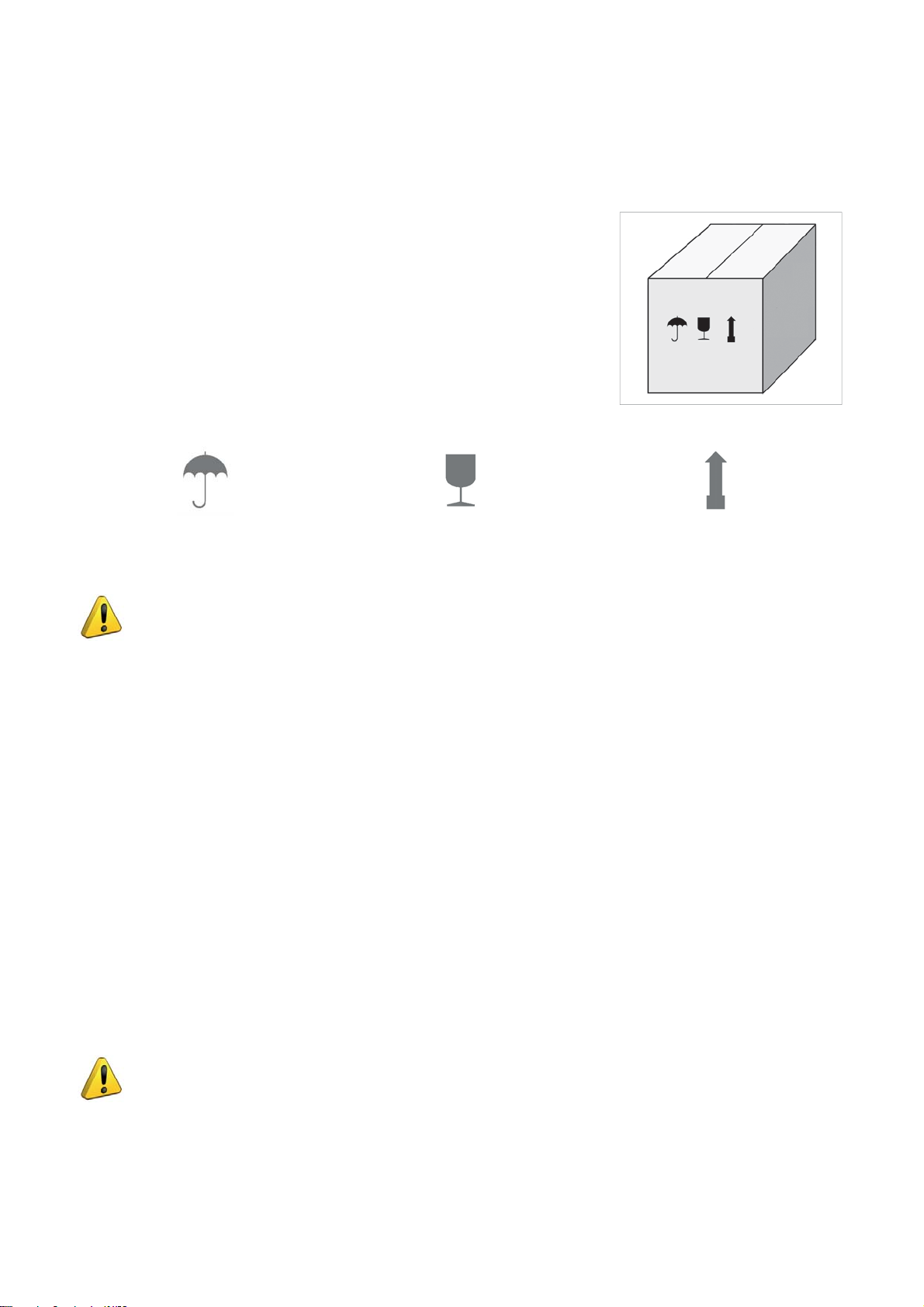
The packing for the FUTURA PRO key-cutting machine ensures safe handling
of the machine and all its components.
Packing comprises expanded plastic material wrapped around the machine.
The robust cardboard box in which it is placed and the nylon wrapping protect
the machine even when stored for a long period.
Fig. 9
Keep dry Handle with care Up
The symbols on the outside of the cardboard box give indications for transport.
ATTENTION: keep the complete packing for future machine transfers.
2.2 UNPACKING
To remove the machine from its packing:
1) Cut the strapping with scissors and remove.
2) Open the box carefully without damaging it.
3) Free the machine from the protective shells.
4) Check the contents of the packing, comprised of:
-
FUTURA PRO key-cutting machine
-
documentation comprising: user’s manual, spare parts sheet, specialist guide and warranty
-
tablet
-
tablet stand
-
power lead
-
power pack
-
tool kit
-
fi xing bracket
2.3 HANDLING THE MACHINE
Once removed from its packing place FUTURA PRO directly on the work bench; one person can easily perform
this operation.
ATTENTION: lift the machine by holding onto the base. Never lift the machine by gripping the
clamps, levers or other parts.
10
Copyright Silca 2018
Page 15
Operating manual FUTURA PRO
3 MACHINE INSTALLATION AND PREPARATION
Installation is the customer’s task and does not require any special skills.
The key-cutting machine is supplied ready for use and does not need calibration except for the tools to be used
and any additional jaws that are included with the machine; however, the operator is required to make certain
checks and prepare the machine for use.
NOTE: the machine is shipped with a steel rod installed in the cutter shaft to prevent the allen screw
from backing out during transit. REMOVE THE ROD AND INSTALL THE PROPER CUTTER PRIOR TO
ATTEMPTING TO CUT A KEY!
3.1 CHECKING FOR DAMAGE
FUTURA PRO is a solid compact machine and will not break if handling, unpacking and installation are carried out
to the instructions in this manual. However, it is good practice to check that the machine has not been damaged.
3.2 ENVIRONMENTAL CONDITIONS
To make the most of the key-cutting machine, bear in mind the following environmental parameters: it is advisable
for the area to be dry with good air circulation.
The optimum environmental conditions for machine operation are:
- temperature 10° C to 40°C;
- relative humidity: approx 60%.
3.3 POSITIONING
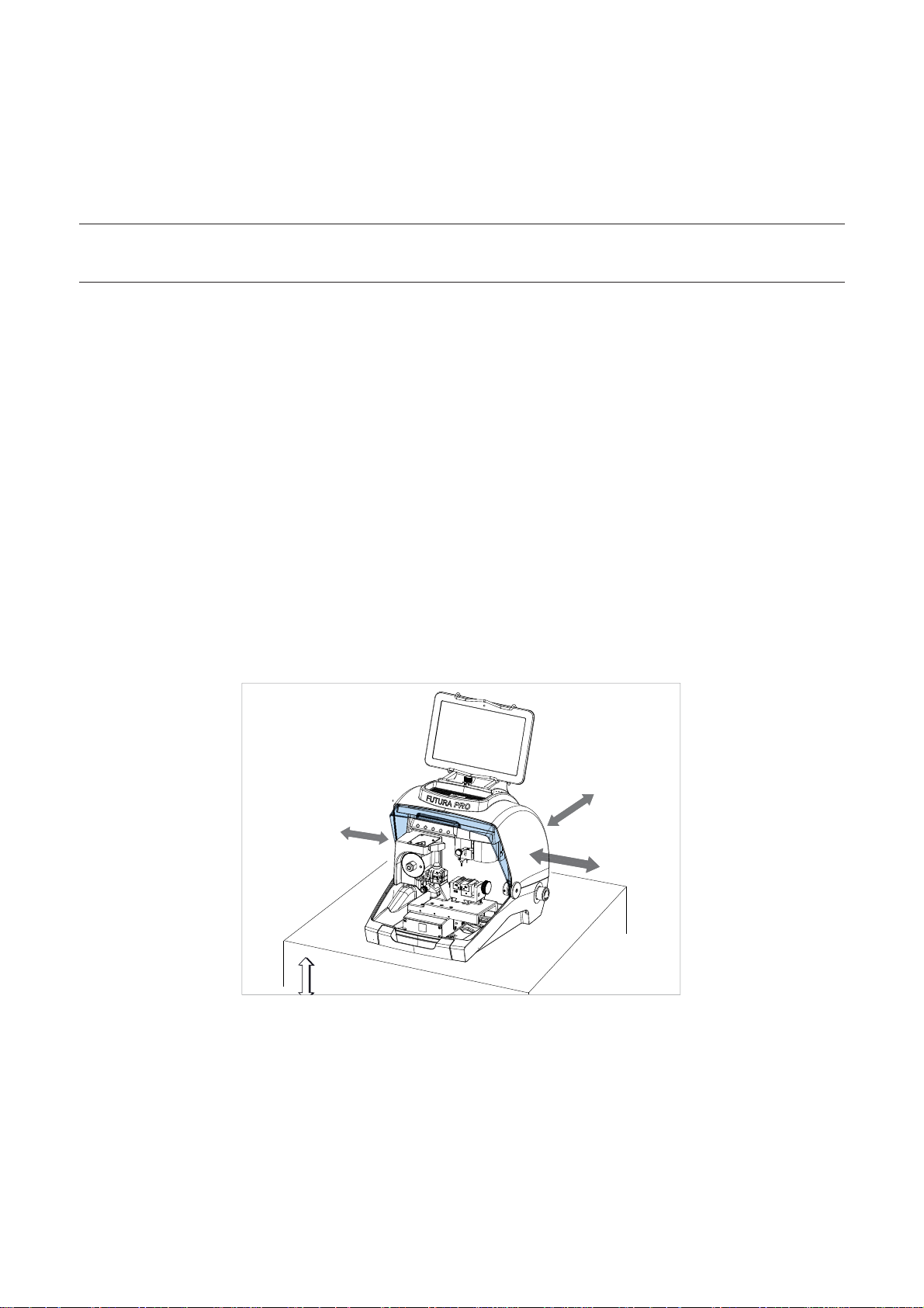
1) Place the key-cutting machine on a solid horizontal work bench suitable for the weight of the machine (20
Kg). The work bench should be approximately 100-120 cm high to facilitate access to the working parts. We
recommend leaving at least 30 cm clearance behind and around the machine to ensure good ventilation and
facilitate handling (Fig. 10).
2) Make sure machine voltage is suitable for the mains supply and that the latter is earthed with a differential switch.
3) Connect the power lead (power pack) to the machine (chap.3.4.2).
30 cm
100/120 cm
30 cm
30 cm
Fig. 10
Copyright Silca 2018
11
Page 16
Operating manual FUTURA PRO
3.4 SEPARATE PARTS
The machine packing also contains the following components, separately packed:
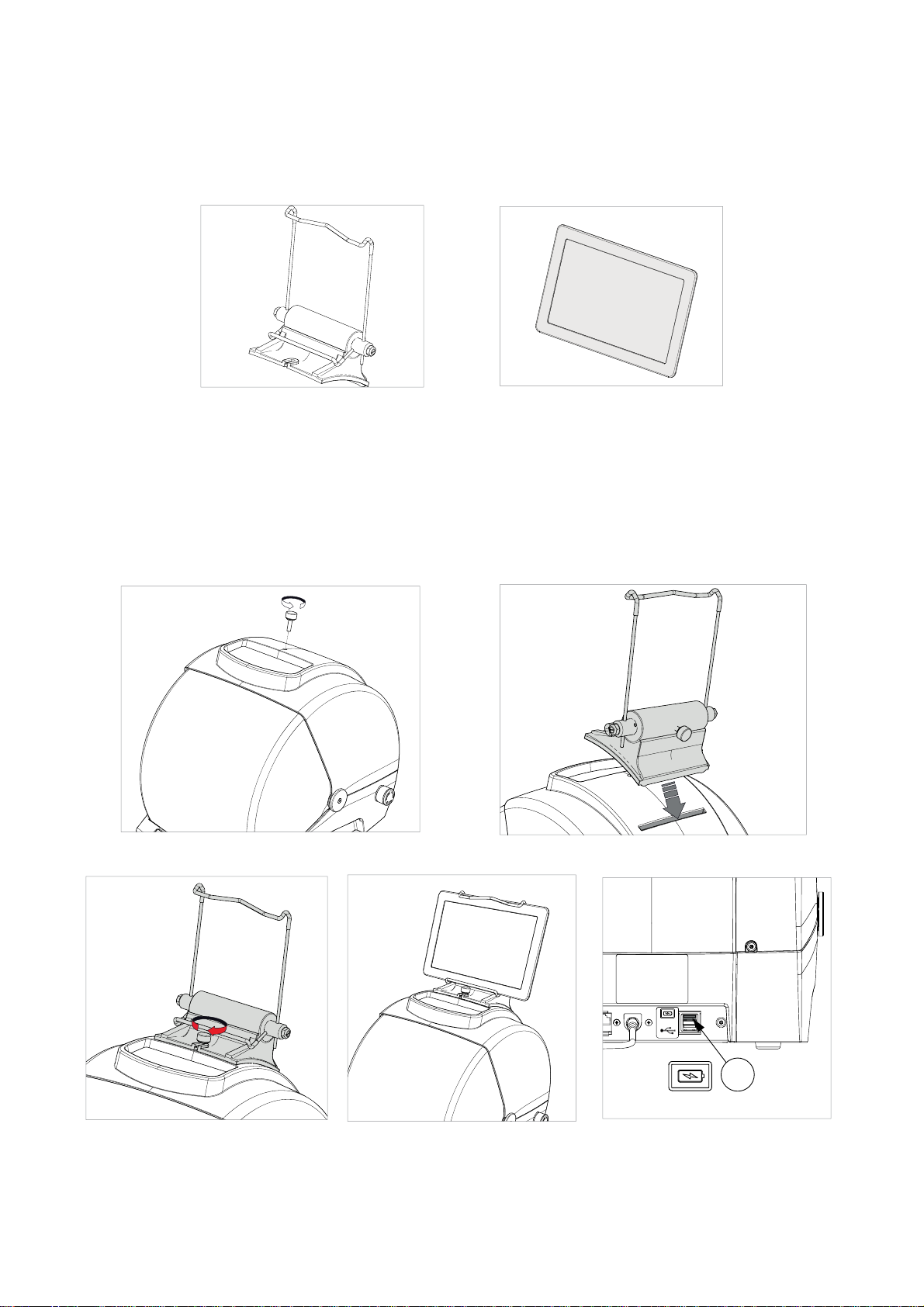
3.4.1 Tablet stand and tablet
Fig. 11 Fig. 12
These items are separate from the machine and must be unpacked and installed by the operator in the way
described below:
1) Remove the 2 items from their packing.
2) Loosen the knob on top of the machine cover (Fig. 13).
3) Install the tablet stand so that the special profi le fi ts into the slot on the machine cover (Fig. 14).
4) Screw down and tighten the knob to secure the tablet stand to the cover (Fig. 15).
5) Fit the tablet into its stand (Fig. 16).
Fig. 13 Fig. 14
Y
Fig. 15 Fig. 16 Fig. 17
6) Connect the tablet USB/Micro USB cable to the USB tablet port (Y) located on the back of Futura PRO.
12
Copyright Silca 2018
Page 17
Operating manual FUTURA PRO
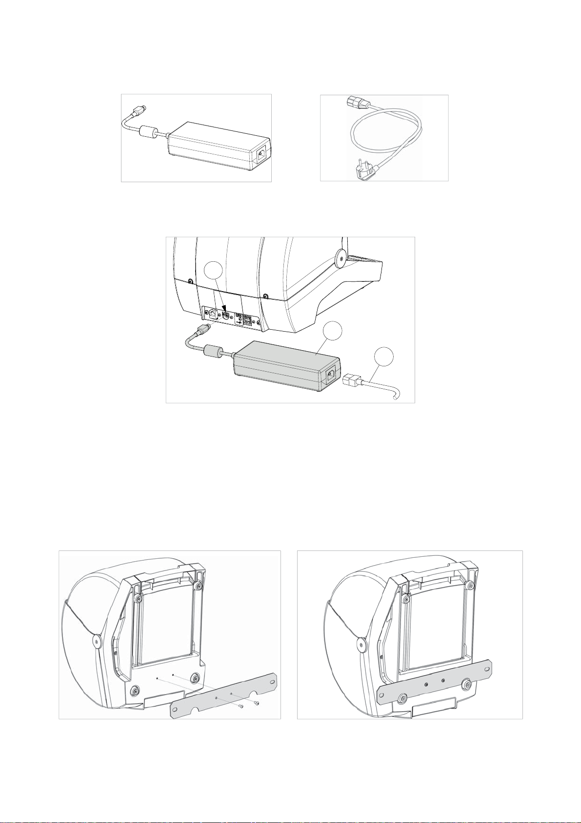
3.4.2 Power pack and lead
Fig. 18 Fig. 19
Connect FUTURA PRO to the power pack (W) and connect the latter to the power supply with the power lead
(W2).
W1
W
W2
Fig. 20
3.4.3 Fixing bracket
If the key-cutting machine is transported and used on a vehicle, e.g. a van, it must be prepared as follows:
1) Turn off the machine and detach the power lead.
2) Remove the tablet holder and tablet.
3) Turn the key-cutting machine onto its back.
4) Connect the fi xing bracket to the machine and secure with the 2 screws.
5) Return the machine to its upright position on the work top.
Fig. 21 Fig. 22
Copyright Silca 2018
13
Page 18
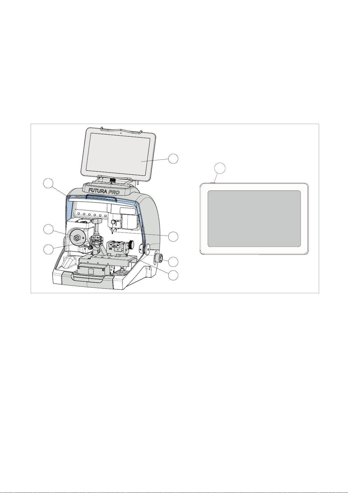
Operating manual FUTURA PRO
3.5 WORK STATION DESCRIPTION
One operator is enough to operate the machine, which has the following operating parts:
• General ON/OFF/emergency button (R) located on the right-hand side of the machine
• Key holding clamps (M) (P)
• Tablet (B)
• Tablet ON button (B1)
• Safety shield (C)
• Cutters (F) (G)
B
B1
C
F
M
MACHINE POWER ON
Rotate the red button (R) to turn on the machine.
G
R
P
Fig. 23
14
Copyright Silca 2018
Page 19
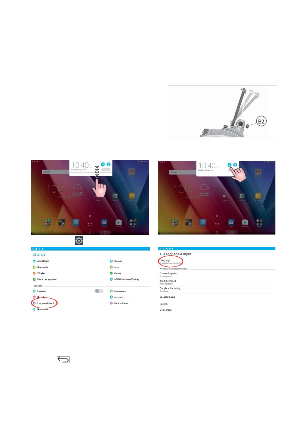
Operating manual FUTURA PRO
4 TABLET REGULATION AND USE
1) Connect the tablet to a power source by means of its power pack in order to charge it (3 hours for the fi rst
charge). The tablet can also be charged connected to the specifi c USB port (Y) on the back of the machine (Fig.
17, page 12).
2) Turn on the tablet by holding down the push button (B1) (Fig. 23) holding it down for a few seconds.
REGULATING TABLET INCLINATION
1) Loosen the knob (B2).
2) Incline the stand as required.
3) Tighten the knob (B2).
Fig. 24
4.1 CHOICE OF LANGUAGE
1) Select “Settings” .
2) Scroll up with your fi nger.
3) Select Language & Input and then Language.
4) Scroll and select the desired language.
5) Select Silca Keyboard (if desired)
6) Select Display > Sleep > Never. This will prevent the application from timing out and closing the session.
7) To quit:
• For all software functionalities on board the Silca key-cutting machine, see the SOFTWARE
OPERATING GUIDE on your tablet (Ch.10).
• Further instructions are given in the quick guide for the tablet.
Copyright Silca 2018
15
Page 20
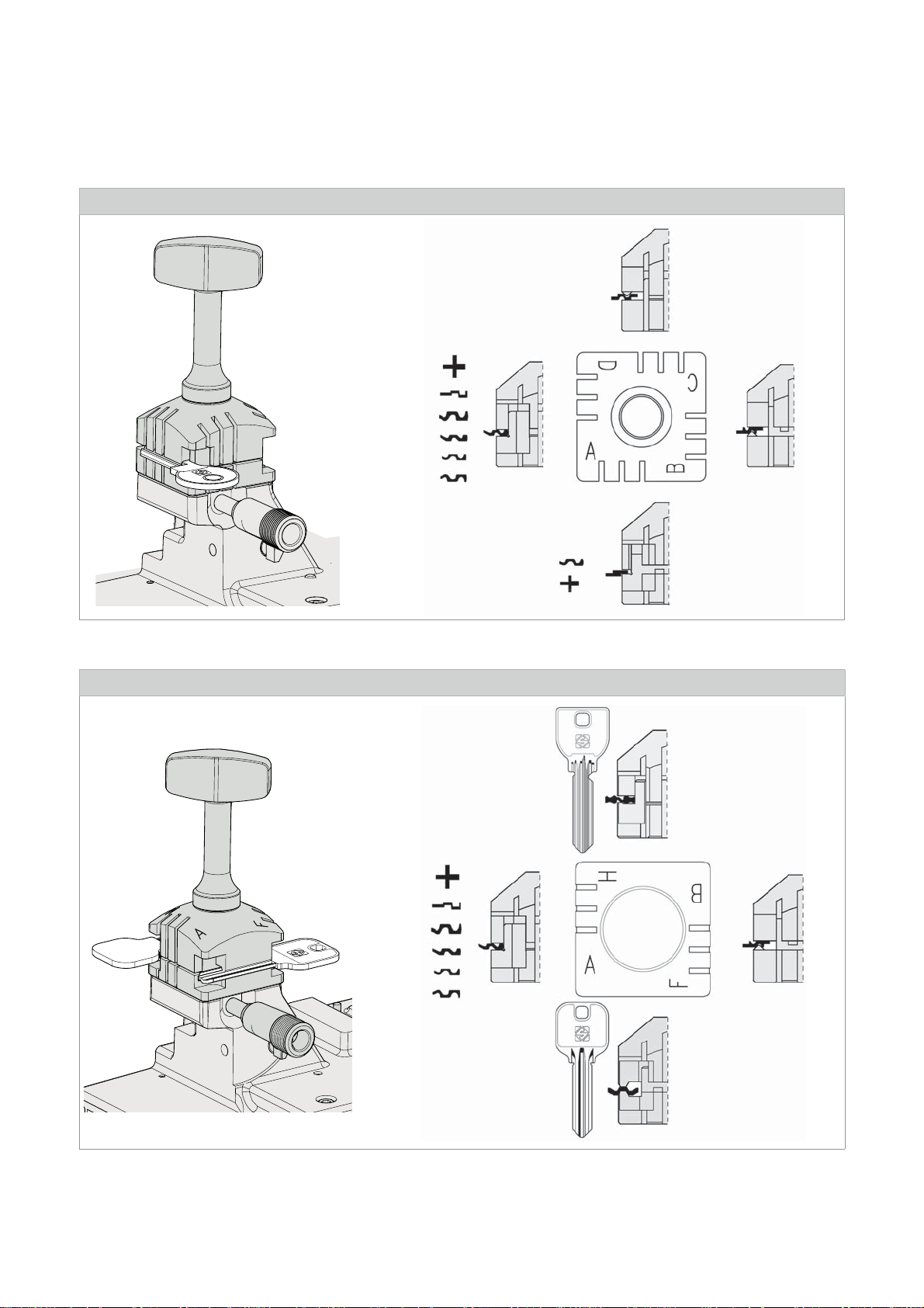
Operating manual FUTURA PRO
5 CLAMPS
5.1 CLAMPS FOR FLAT KEYS WITH STANDARD CUTS
01V CLAMP: FUTURA PRO - FUTURA PRO NA
Fig. 25 - 01V clamp
01VJ CLAMP: FUTURA PRO JAPAN
16
Fig. 26 - 01VJ clamp
Copyright Silca 2018
Page 21
Operating manual FUTURA PRO
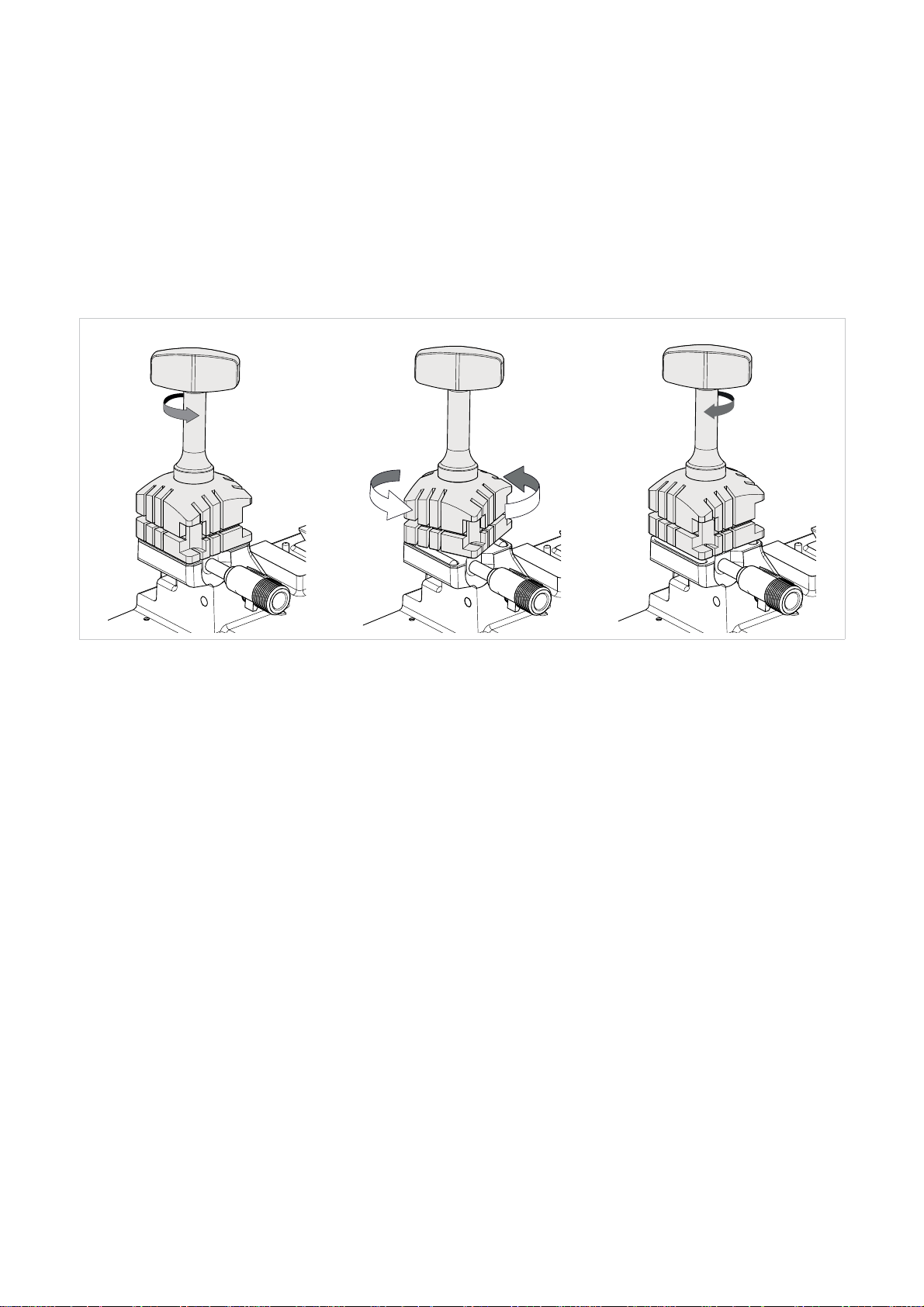
The use of one of the clamp sides is required, according to the type of key to be decoded and/or cut by copying
or by code (Fig. 25 and Fig. 26). Positioning the correct side to be used is quick and easy. With the clamp jaws
slightly open, turn the clamp by hand to position it as required, facilitated by a new special alignment system (Fig.
27).
The 4-sided clamp is used to secure keys fi rmly up against the back and on the profi le.
• To copy keys (these can be locked on any of the clamp sides A, B, C or D), the user will decide which side is
the most suitable.
• To decode a key you MUST use the clamp designated by the software.
• For code key-cutting the choice of clamp to use is established by the software.
Fig. 27 - CLAMP ROTATION
Copyright Silca 2018
17
Page 22
Operating manual FUTURA PRO
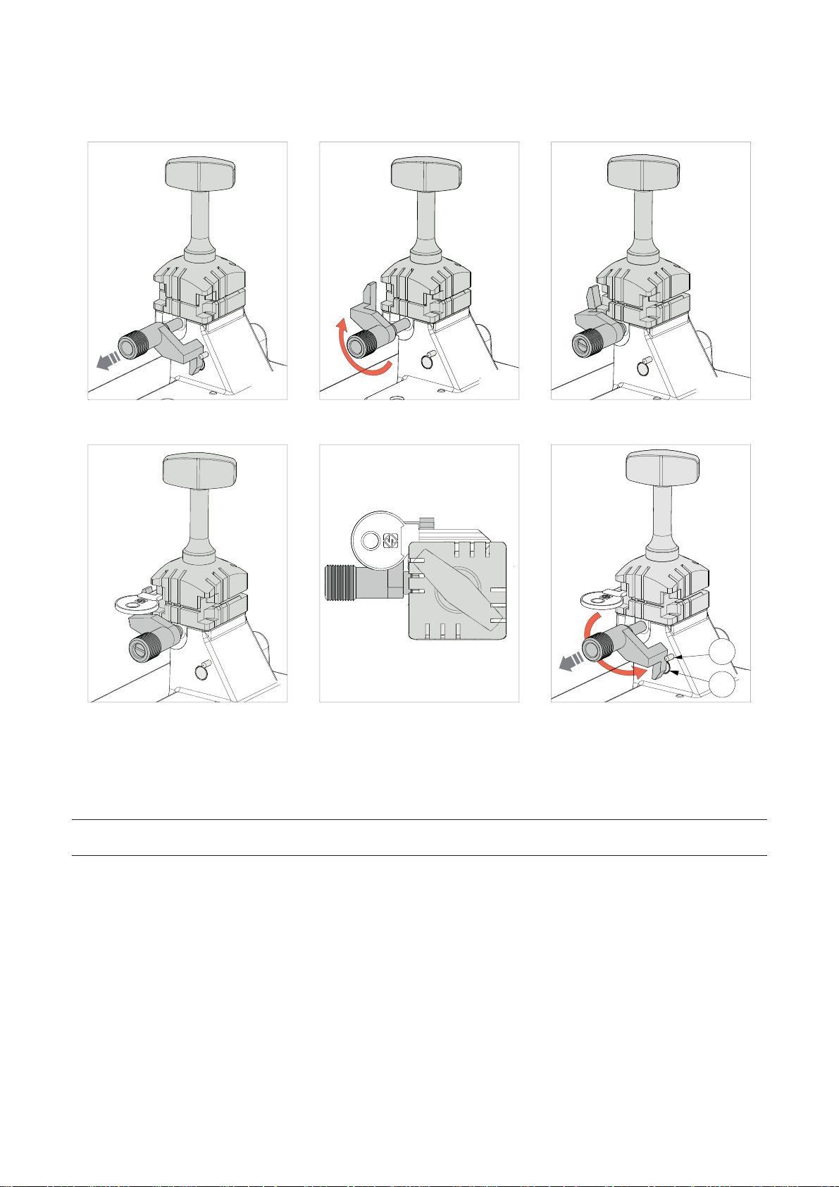
5.1.1 Use of the shoulder gauge
The gauge is used to position fl at cylinder or vehicle keys that call for Stop 0 (Fig. 34).
Fig. 28 Fig. 29 Fig. 30
I3
I2
Fig. 31 Fig. 32 Fig. 33
Pull the gauge gently towards the operator, turn clockwise by about 180° and release against the clamp.
Fit the sample key into the clamp with the stop up against the gauge.
Use the bar or tip stop (provided) for keys without stops that measure from the tip (cap.5.1.2).
The choice of position 1-2-3-4 depends on the length of the cut.
NOTE: take the gauge back by hand to its original position before starting to read or cut the key (Fig.
33).
For all reading/decoding and cutting operations the gauge (I) must be taken back manually to its original position
(Fig. 33 - in this position it covers the sensor (I2) which detects it).
To take the gauge to its original position (with the gauge up against the key stop) proceed as follows:
1) Turn counter-clockwise;
2) Pull towards the operator and continue to rotate counter-clockwise until it comes up against the stop pin (I3);
3) Release the gauge.
18
Copyright Silca 2018
Page 23
Operating manual FUTURA PRO
5.1.2 Stop positions (key stop)
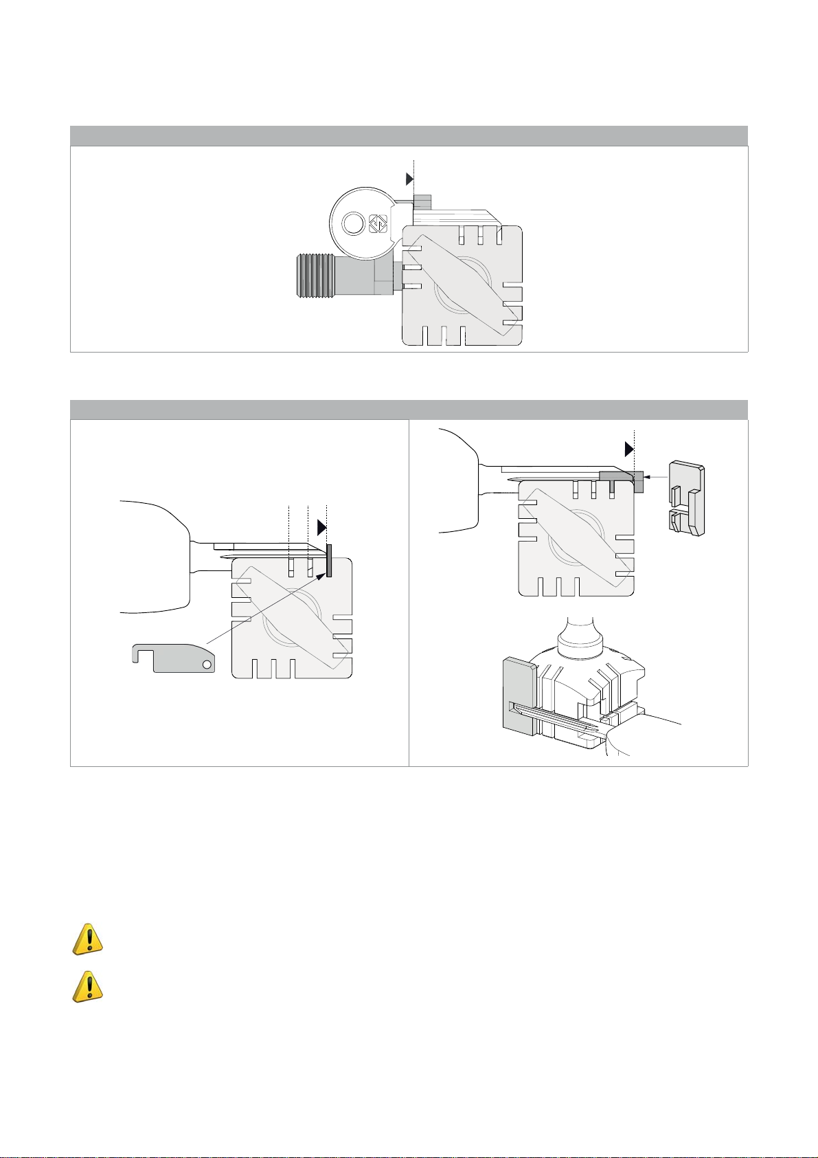
HEAD STOP
0
Fig. 34 - Stop 0
TIP STOP
4
123
Fig. 35 : Stop 1 - 2 - 3 Fig. 36 : Stop 4
According to the length of the stem the following accessories are provided to install keys with tip stops (chap.1.4):
• Stop bar (Fig. 35)
For keys that need Stop 1, 2 or 3. Insert the bar into the grooves provided.
• Tip Stop 4 (Fig. 36)
For long keys that need Stop 4. Install as per Fig. 36.
ATTENTION: stop bar and tip stop must be removed before decoding or cutting operations.
ATTENTION: it is not necessary to apply force to close the clamp properly.
Copyright Silca 2018
19
Page 24
Operating manual FUTURA PRO
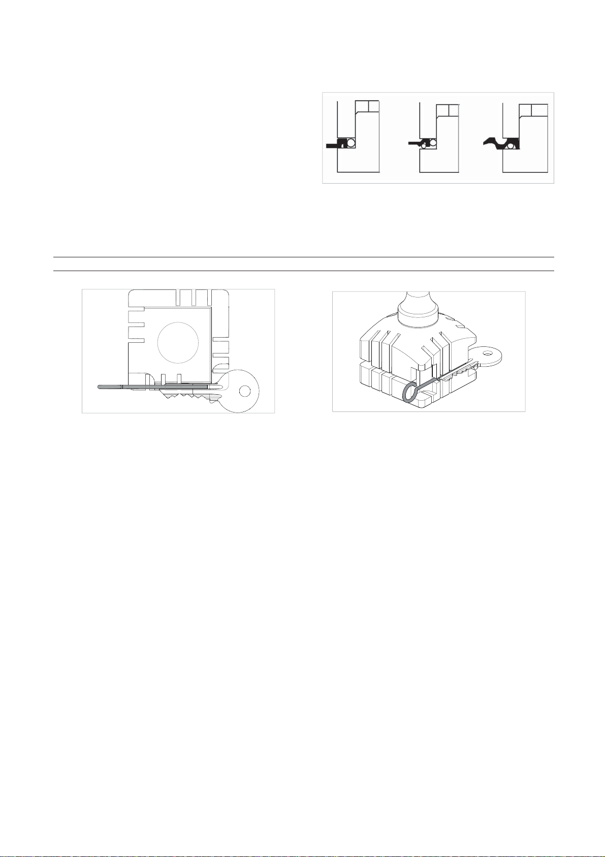
5.1.3 Use of pins - CLAMP 01V / 01VJ
For keys with narrow stems the pins must be placed
between the bottom of the clamp and the back of the key
so that the key protrudes suffi ciently out of the clamp and
therefore can be properly read and cut.
If the key has a narrow stem and is also very thin, 2 pins
must be used (Fig. 37).
Fig. 37
If the original key is broken, place a suitable sized pin in the groove of the keys stem so that it is properly held in
place and therefore can be copied (Fig. 38).
NOTE: use a pin with the same diameter for both decoding and cutting.
Fig. 38 Fig. 39
20
Copyright Silca 2018
Page 25
Operating manual FUTURA PRO
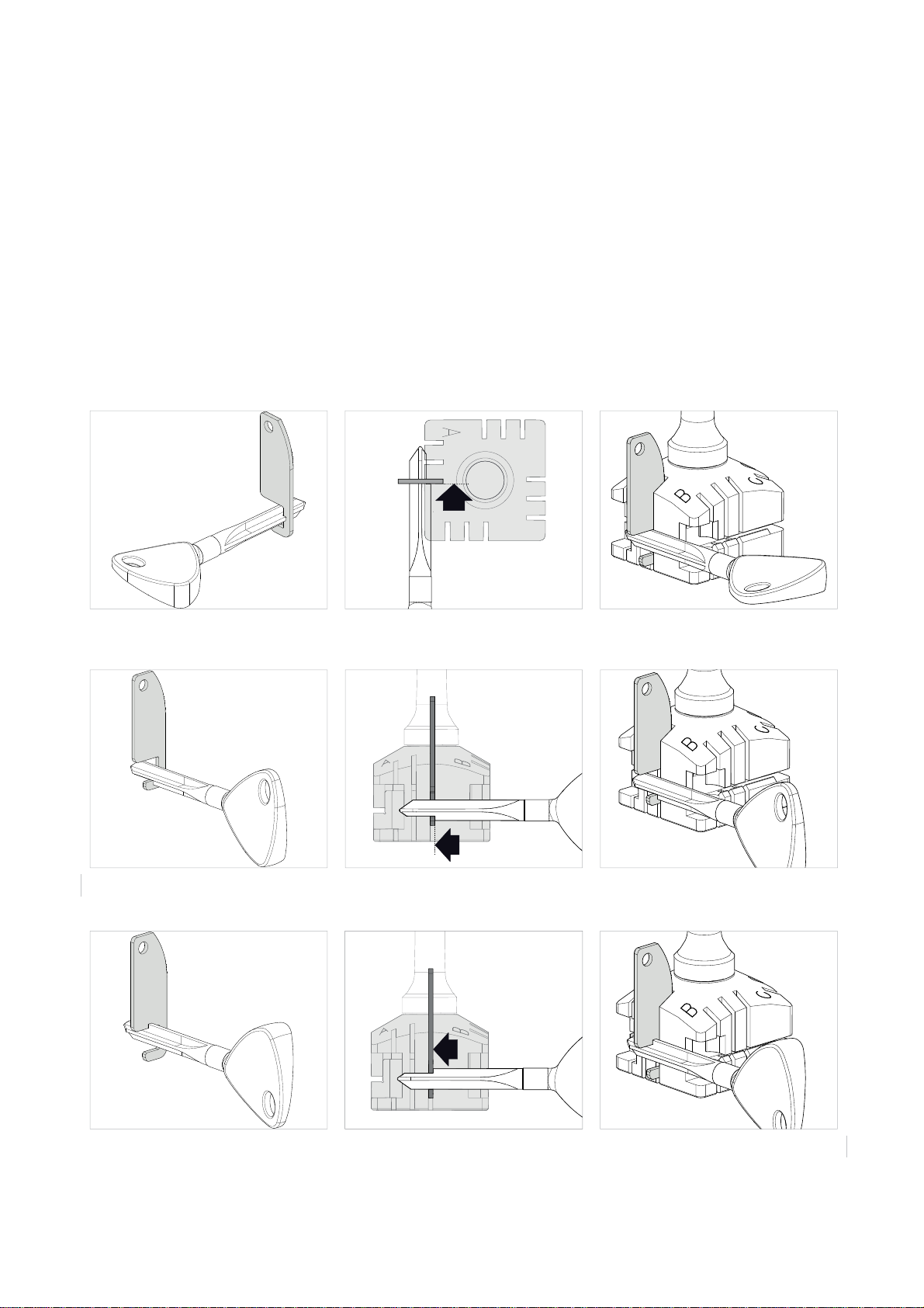
5.1.4 Cutting cruciform keys (with 3 fi ns)
The standard 4-sided clamp can be used to cut almost all cruciform keys (except for Y and T shaped ones).
1) Leave the gauge in its original position.
2) Fit the key into the clamp:
- Insert the grooved bar into the notch on the clamp according to the key stop (as shown in Fig. 40 - Key stop
towards the inner part of the clamp, Fig. 41 - Key stop DOWN and Fig. 42 - Key stop UP).
- Butt the key stop up against the bar.
3) Tighten the knob (M1) to secure the key.
4) Remove the bar.
ATTENTION: the cuts on each fi n are different.
POSITION OF KEY AND BAR
Fig. 40 - Key stop towards the INNER PART of the clamp
Fig. 41 - Key stop DOWN
Fig. 42 - Key stop UP
Copyright Silca 2018
21
Page 26
Operating manual FUTURA PRO
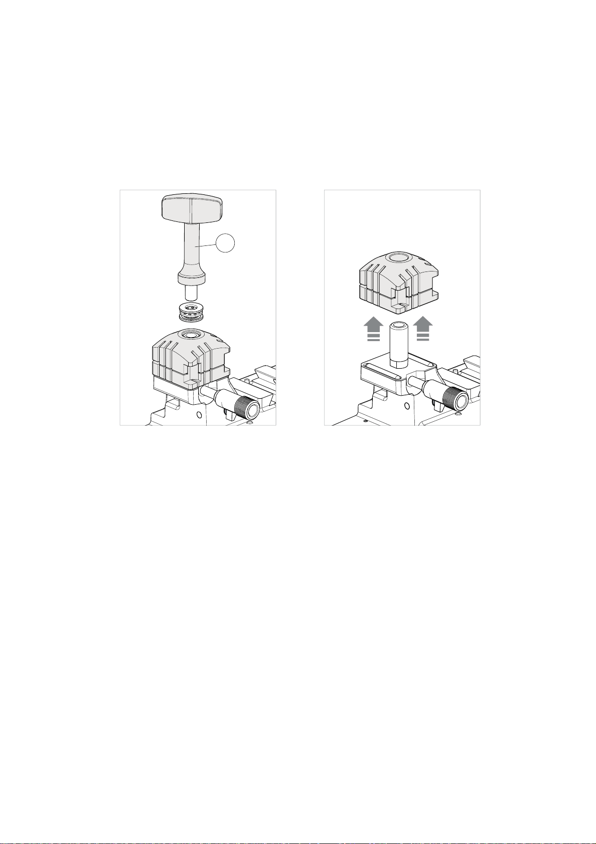
5.1.5 Removing/fi tting the clamp 01V / 01VJ
1) Raise the safety shield.
2) Unscrew the knob (M1) and remove together with the washer set (Fig. 43).
3) Pull the clamp upwards (Fig. 44).
4) Carefully clean the seat of the clamp support.
5) Clean the clamp before fi tting into the support.
6) Tighten the knob (M1) with the washer set.
M
Fig. 43 Fig. 44
22
Copyright Silca 2018
Page 27
Operating manual FUTURA PRO
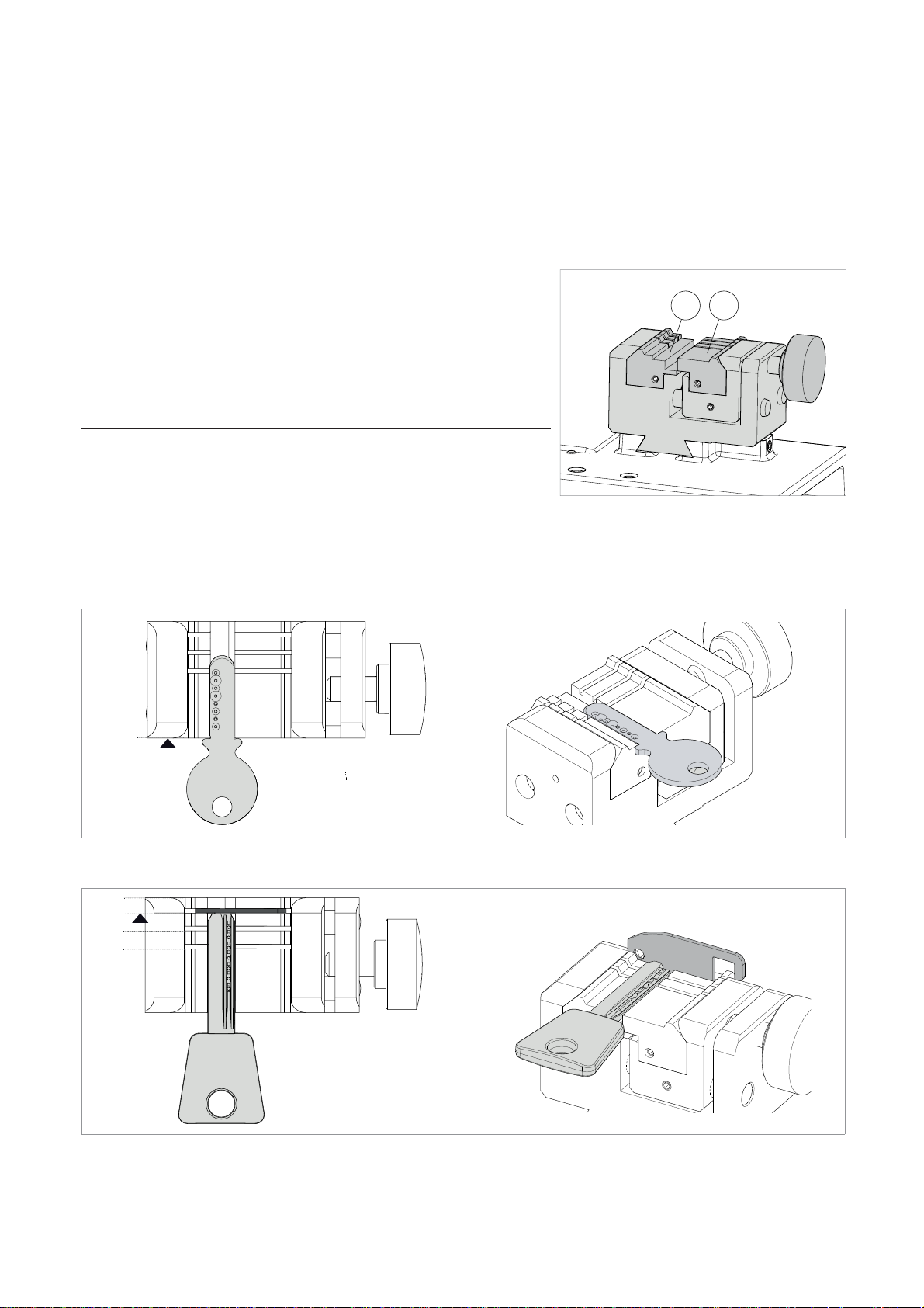
5.2 LAMP FOR DIMPLE AND TRACK KEYS - 01R
According to the type of key to be decoded and/or cut, follow the instructions in the Silca tablet program regarding:
• clamp
• use of jaws (Q1) and (Q2)
• clamp stop (Fig. 46 and Fig. 47)
FITTING THE KEY
The clamp is designed to house high security keys with shoulder stop
or tip reference.
For shoulder stop keys, place the shoulder of the key against the jaws
(stop “0”) (Fig. 46) and the others (tip stop) must be placed against
one of the grooves (1-2-3-4), as indicated in the Silca tablet program.
For this operation use the bar provided (Fig. 47).
NOTE: the stop bar must be removed before decoding or
cutting operations.
1) Fit the key to be cut into its seat and ensure it is resting fi rmly on
the clamp plate.
2) Tighten the knob (M) to secure the key.
Q
Q
2
1
Fig. 45
5.2.1 DIMPLE keys
0
4
3
2
1
Fig. 46 - SHOULDER STOP
Fig. 47 - TIP STOP
Copyright Silca 2018
23
Page 28
Operating manual FUTURA PRO
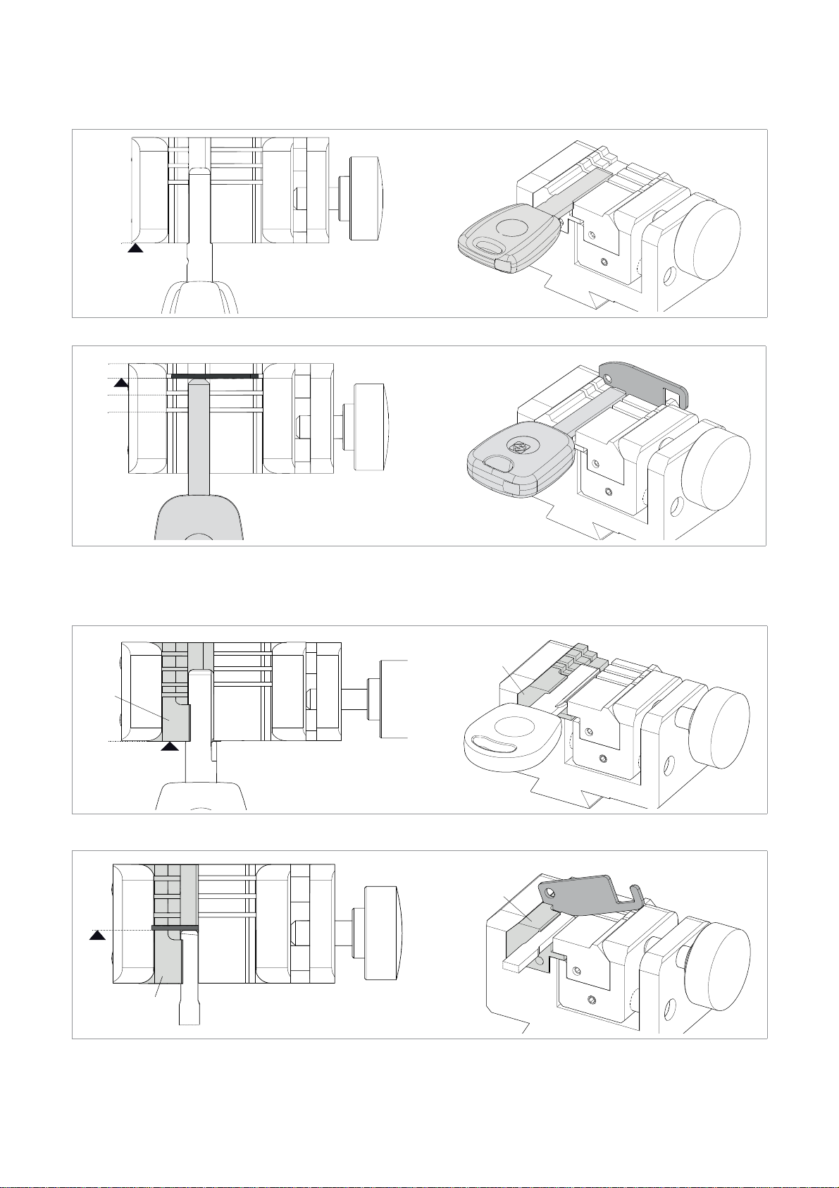
5.2.2 TRACK type keys
0
Fig. 48 - SHOULDER STOP
4
3
2
1
Fig. 49 - TIP STOP
5.2.3 TRACK type keys (Futura PRO NA - Futura PRO Automotive)
19J
19J
0
Fig. 50 - HU66 on Futura PRO NA and Futura Automotive
19J
24
19J
Fig. 51 - Ford Escape key on Futura PRO NA and Futura PRO Automotive
Copyright Silca 2018
Page 29
Operating manual FUTURA PRO
5.3 REMOVING / FITTING CLAMP 01R
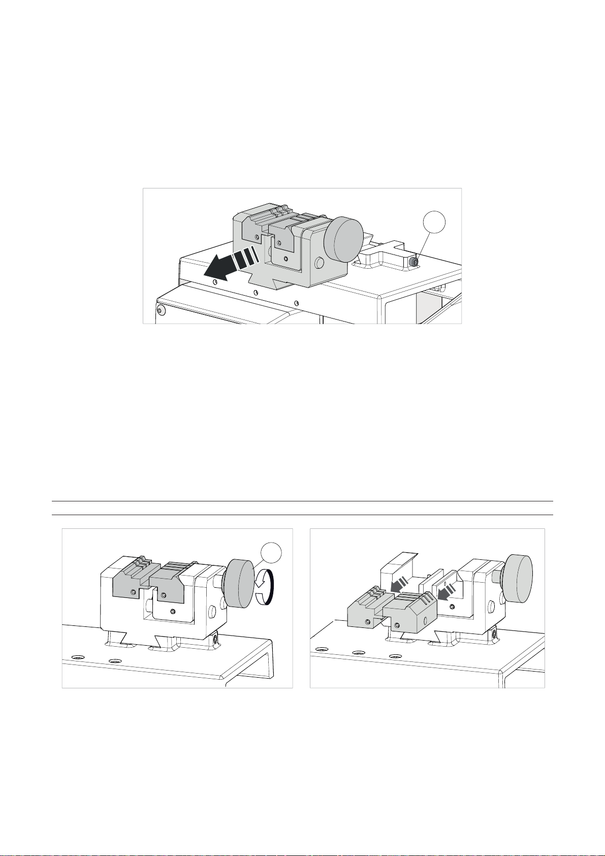
1) Raise the safety shield.
2) Loosen the grub screw (P2) and remove the clamp by pulling it towards the operator.
3) Carefully clean the clamp support seat.
4) Clean the clamp before fi tting into the support.
5) Fit the clamp (with knob on the right) into the special dovetail and take up against the stop pin.
6) Tighten the grub screw (P2) to secure the clamp.
P2
Fig. 52
5.4 REMOVING/FITTING THE JAWS ON CLAMP 01R
1) Raise the safety shield.
2) Loosen the knob (P1) by a couple of turns (Fig. 53).
3) Use your fi ngers to pull the jaw to be removed out towards the operator (Fig. 54).
4) Carefully clean the seat of the jaw on the clamp.
5) Clean the jaw before fi tting into the clamp.
6) Fit the jaw up against the stop pin.
NOTE: there is only one way to fi t the jaw into the clamp.
P
1
Fig. 53 Fig. 54
Copyright Silca 2018
25
Page 30
Operating manual FUTURA PRO
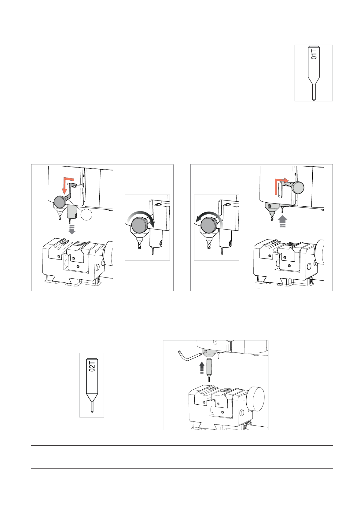
5.5 USING TRACER 01T
The tracer 01T is used to read/decode both dimple and track keys.
This tracer may or may not be required according to the type of key to be decoded and the
dimensions involved.
ATTENTION: Anodised aluminium keys, plastic keys or any other key without electrical
conductivity CANNOT BE decoded!
Fig. 55
• ACTIVATING THE TRACER 01T (Fig. 56)
-
To use the tracer: move the lever (J1) to the left and lower the tracer.
-
When the tracer is lowered, turn the lever knob clockwise.
• EXCLUDING THE TRACER 01T (Fig. 57)
-
Turn the lever knob counterclockwise.
-
Take the tracer to the idle position: raise the lever (J1) and move to the right.
J1
Fig. 56 Fig. 57
5.6 TRACER 02T
Some applications may require the use of the 02T tracer. The 02T tracer (when required) should be placed into
the cutter shaft (replacing the cutter) (Fig. 59).
Note: fi t the new tracer pushing all the way upwards.
02T
Fig. 58 Fig. 59
NOTE: for cutting and/or decoding operations with the tracer point 02T, the tracer 01T must be in
the idle position (Fig. 57). REPLACE THE 02T TRACER WITH THE REQUIRED CUTTER PRIOR TO
ATTEMPTING TO CUT A KEY.
26
Copyright Silca 2018
Page 31
Operating manual FUTURA PRO
5.7 ENGRAVING
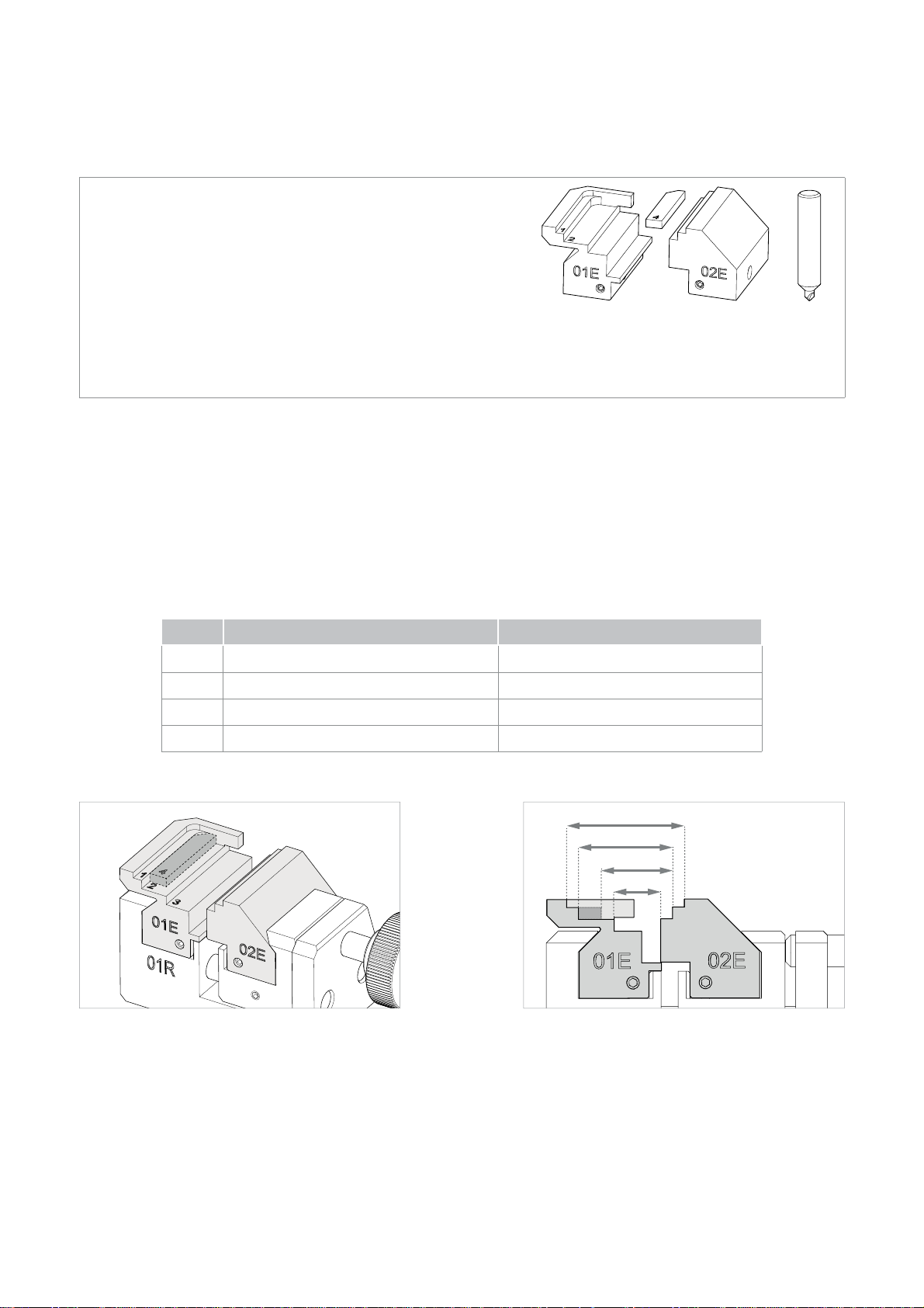
The ENGRAVING function requires the following accessories:
• Jaw 01E (code D748737ZB)
• Jaw 02E (code D748739ZB)
• Adapter for plane 4 (code D750763ZB)
3
18DW
• Cutter 18DW specifi c for engraving (code D748741ZB)
The accessories are:
STANDARD on the FUTURA PRO ENGRAVING version
OPTIONAL for all other versions of FUTURA and FUTURA PRO
Fig. 60
Insert jaws 01E and 02E into the 01R clamp and gauge.
-
-
Open jaws 01E and 02E and fi t the key head or medal to be engraved (further details in the SOFTWARE Operating
Guide or online HELP desk).
ATTENTION: objects MUST BE METAL, NOT STAINLESS STEEL. Materials such as wood, paper, plastic
and ceramics cannot be engraved. Make sure the surface of the object to be engraved is fl at.
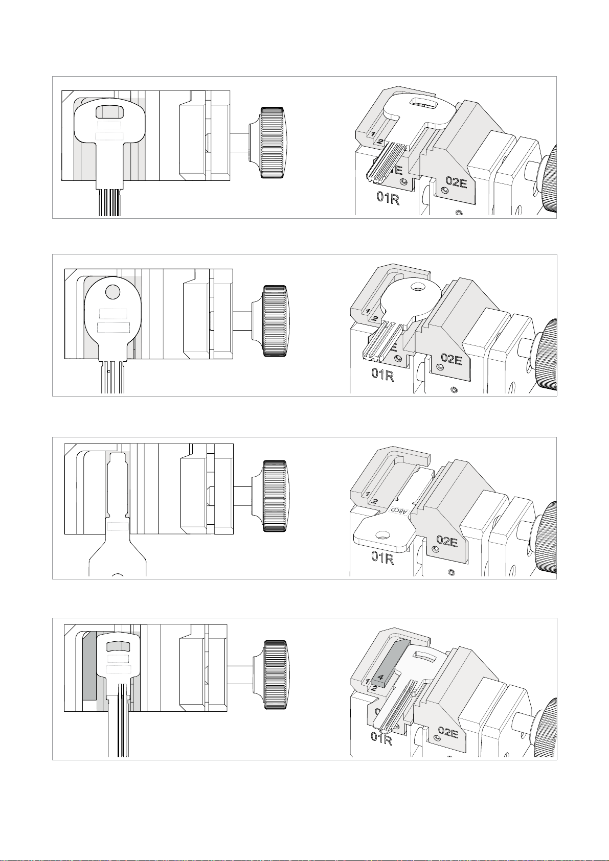
The jaw/adapter kit runs 4 different planes/housings (Fig. 62) according to the size of the medal or key head to
be engraved, and/or according to the position of the head, as shown in the Software Guide.
PLANE WIDTH of the object to be engraved ENGRAVING AREA (L x H)
1
min 26 - max 32 mm 32 mm x 40 mm
2 min 20 - max 26 mm 24 mm x 36,5 mm
3 min 8 - max 14 mm 12 mm x 36,5 mm
4 min 14 - max 20 mm 18 mm x 36,5 mm
1
2
4
3
Fig. 61 Fig. 62
Copyright Silca 2018
27
Page 32
Operating manual FUTURA PRO
abcde
ABCDE
2
1
Fig. 63 - plane 1
abcde
ABCDE
1
12
2
Fig. 64 - plane 2
ABCD
Fig. 65 - plane 3
28
abcde
ABCDE
4
12
Fig. 66 - plane 4
Copyright Silca 2018
Page 33
Operating manual FUTURA PRO
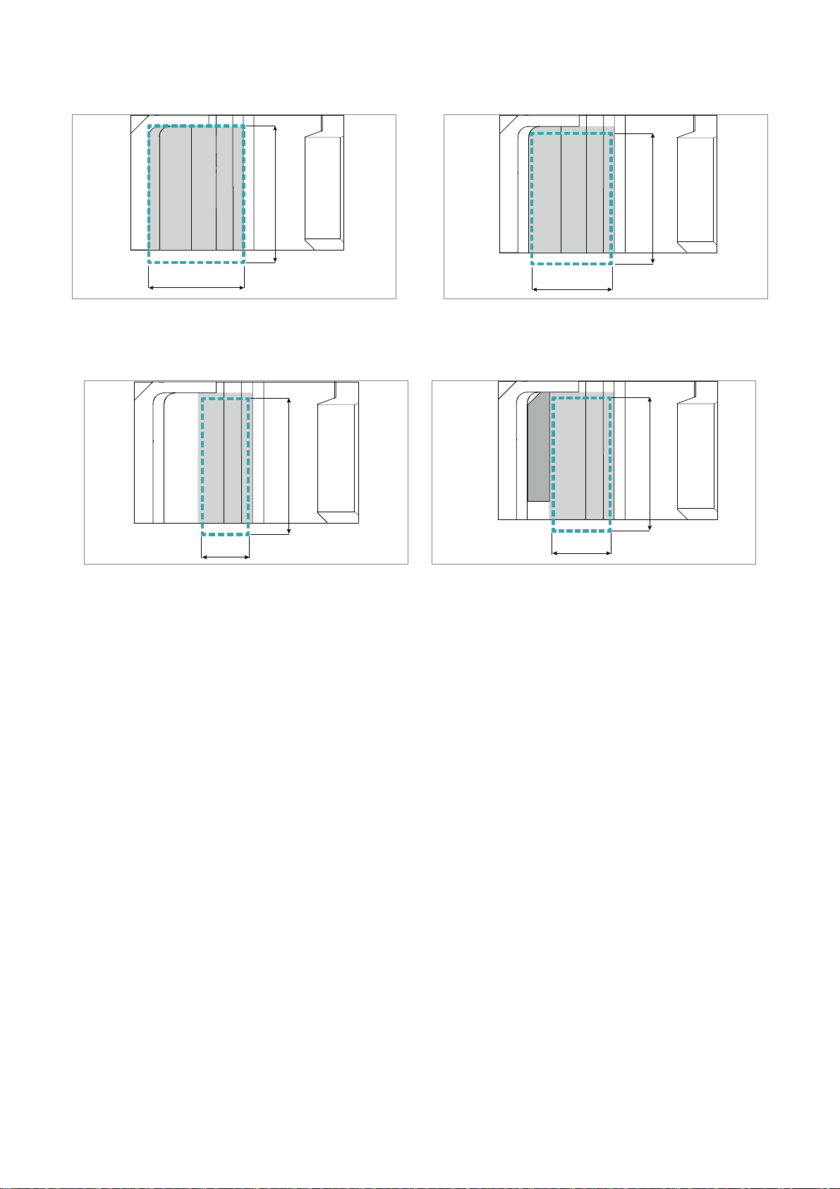
40 mm
321
32 mm
Fig. 67 - ENGRAVING AREA plane 1 Fig. 68 - ENGRAVING AREA plane 2
36,5 mm
321
24 mm
36,5 mm
36,5 mm
4
321
12 mm
21
18 mm
Fig. 69 - ENGRAVING AREA plane 3 Fig. 70 - ENGRAVING AREA plane 4
Further details in the SOFTWARE Operating Guide or online HELP desk.
Copyright Silca 2018
29
Page 34

Operating manual FUTURA PRO
6 CLEANING
• Keep the operational parts of the machine as clean as possible by brushing away the chippings
in areas where they accumulate during cutting operations.
• Under no circumstances should compressed air be used to clear the work zone of chippings
as this will blow them onto the moving parts.
• Never use oily products or thinners for cleaning painted surfaces, clamps, electrical or
electronic connections.
• Make sure the key to be decoded is clean.
30
Copyright Silca 2018
Page 35
Operating manual FUTURA PRO
7 MAINTENANCE
ATTENTION: for repairs or replacement of parts for maintenance, the ‘CE’ mark is guaranteed
only if original spare parts provided by the manufacturer are used.
The FUTURA PRO key-cutting machine does not need special maintenance, but it is good practice to check and
if necessary replace parts subject to wear: cutter, tracer point, belt.
Replacement operations are simple and can be performed by the operator.
ATTENTION: DO NOT USE COMPRESSED AIR!
A TTENTION: to maintain machine effi ciency we recommend using protective oil such as WD40
or similar to apply to the burnished mechanical parts. Make sure the oil does not come into
contact with the electronic parts.
Before performing any type of maintenance (checks or replacements) read the warnings below:
• Do not perform any maintenance operations with the machine on.
• Always disconnect the power lead.
• Follow the instructions in the manual carefully.
• Use original spare parts (see provided spare parts sheet).
7.1 OPERATIONS
• Access to rear compartment
• Prismatic cutter replacement
• Cylindrical cutter and/or tracer point replacement
• Tracer 01T replacement
• Checking and replacing fuse
• Battery replacement
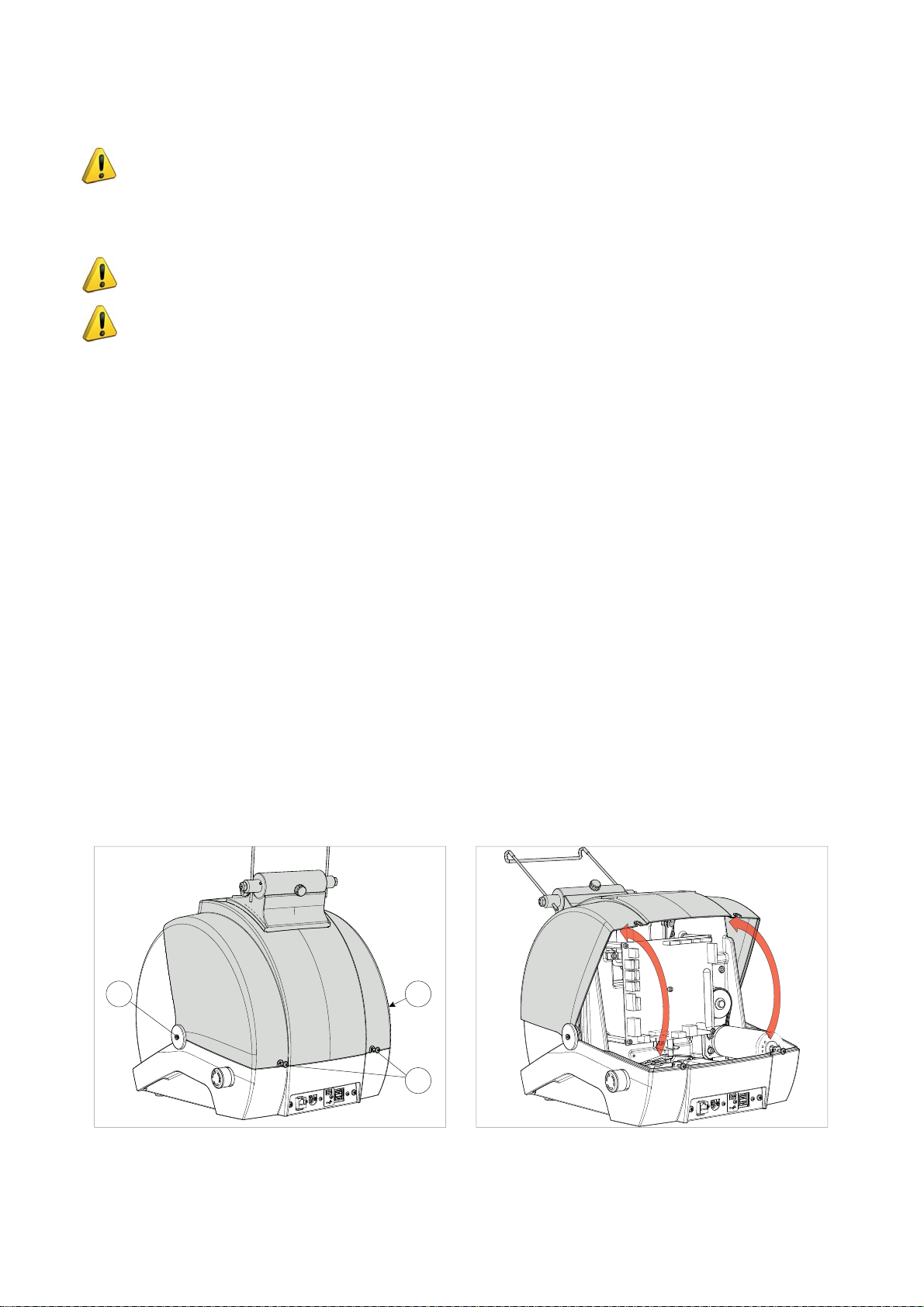
7.2 ACCESS TO REAR COMPARTMENT
1) Turn off the key-cutting machine and disconnect the power lead.
2) Remove the tablet.
3) Loosen the 2 screws (E1) and the 2 screws (E2).
4) Rotate the cover towards the front of the machine.
E2
E2
E1
Fig. 71 Fig. 72
Copyright Silca 2018
31
Page 36
Operating manual FUTURA PRO
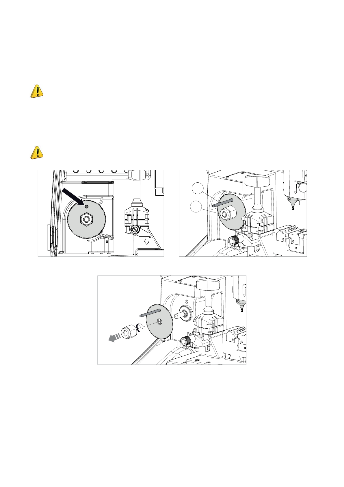
7.3 PRISMATIC CUTTER REPLACEMENT
1) Raise the safety shield.
2) Rotate the cutter by hand to align the cutter slot with the rear slot (on the reader stand).
3) Insert the pin (F1) (provided with the machine) into the 2 slots.
4) Loosen the nut (F2) clockwise.
ATTENTION: the thread is to the left.
5) Remove the nut, pin and cutter.
6) Carefully clean the cutter shaft seat and the new cutter.
7) Fit the new cutter and align the cutter slot with the rear slot (on the reader stand).
8) Insert the pin (F1) (provided with the machine) into the 2 slots.
9) Tighten the nut (F2) counter-clockwise. Attention: the thread is to the left.
ATTENTION: when fi tting a new cutter to replace a worn one, or when fi tting a re-sharpened
one, see ch.7.2 of the SOFTWARE OPERATING GUIDE (on the tablet).
F1
F2
Fig. 73 Fig. 74
Fig. 75
32
Copyright Silca 2018
Page 37
Operating manual FUTURA PRO
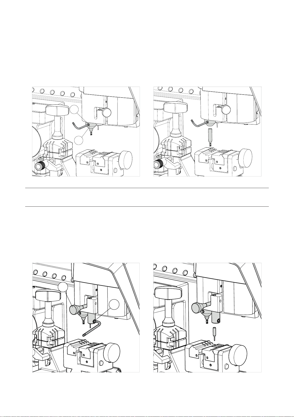
7.4 CYLINDRICAL CUTTER AND/OR TRACER POINT REPLACEMENT
1) Raise the safety shield.
2) Rotate the cutter shaft (G1) by hand and take the grub screw (G2) to the front of the machine.
3) Use a hex key to loosen the grub screw (G2) and remove the tool.
4) Fit the new tool, pushing all the way upwards.
5) Tighten the grub screw (G2) to secure the tool.
G2
G1
Fig. 76 Fig. 77
NOTE: the machine is shipped with a steel rod installed in the cutter shaft to prevent the allen screw
from backing out during transit. REMOVE THE ROD AND INSTALL THE PROPER CUTTER PRIOR TO
ATTEMPTING TO CUT A KEY!
7.5 TRACER 01T REPLACEMENT
1) Raise the safety shield.
2) Move the lever (J1) to the left to lower the tracer.
3) Use a hex key to loosen the grub screw (J2) and remove the tracer.
4) Fit the new tracer, pushing all the way upwards.
5) Tighten the grub screw (J2) to secure the tracer.
J1
J2
Fig. 78 Fig. 79
Copyright Silca 2018
33
Page 38
Operating manual FUTURA PRO
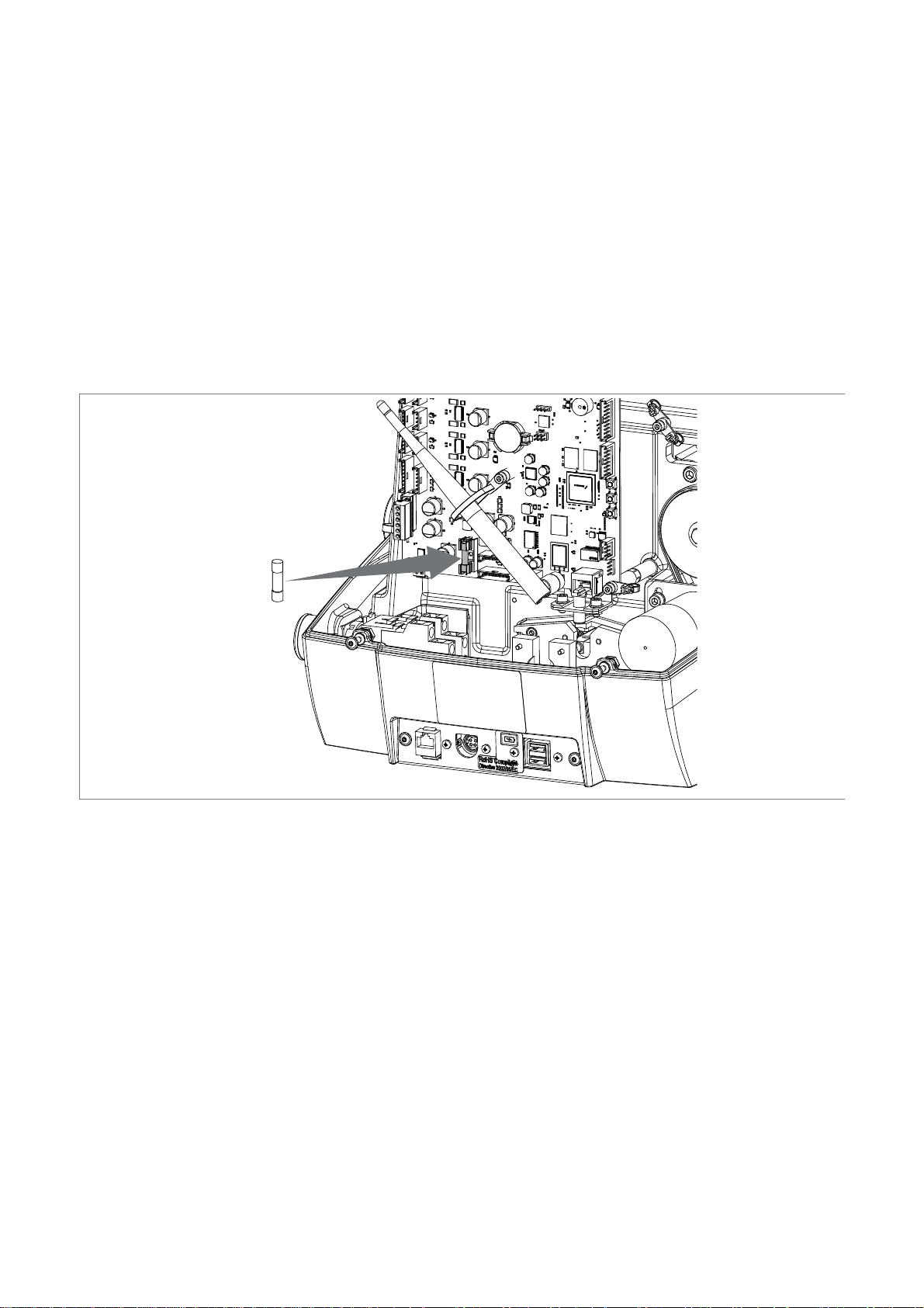
7.6 CHECKING AND REPLACING FUSE
Fuses should be checked with a tester (ohmmeter, multimeter, etc.) as they may appear to be in good condition
even when they are electrically faulty. Fuses must always be replaced with the same amperage and type (rapid
or delayed), as indicated in this manual.
FUTURA PRO has 1 fuse:
4 Amps delayed
Protects the cutters motors and their electronic controls (24V d.c.)
Follow the instructions below to check and, if necessary, replace:
1) Turn off the key-cutting machine and unplug.
2) Access the rear compartment (Ch.7.2).
3) Remove the fuse from its seat (Fig. 78) and replace if necessary.
34
Fig. 80
Copyright Silca 2018
Page 39
Operating manual FUTURA PRO
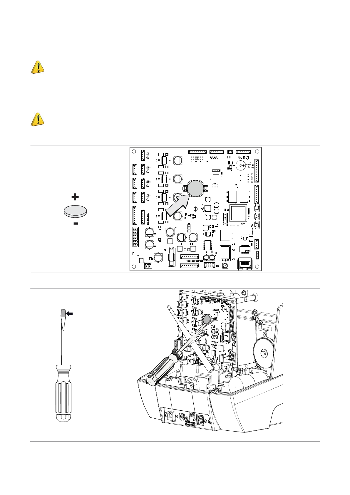
7.7 BATTERY REPLACEMENT
ATTENTION: only specialised personnel can change the battery.
1) Turn the machine off and unplug it from its power supply cable.
2) Access the rear compartment (chap.7.2).
3) Use insulated screwdriver to remove the fl at battery.
4) Insert the new battery into its seat, paying attention to the poles.
ATTENTION: use the same type of lithium battery CR2032 3 Volt.
DANGER OF EXPLOSION IF THE BATTERY IS REPLACED WITH ONE OF THE WRONG TYPE.
5) Follow the instructions in Ch.8 DISPOSAL to dispose of spent batteries.
+
insulated
point
Fig. 81
Fig. 82
Copyright Silca 2018
35
Page 40

Operating manual FUTURA PRO
8 DISPOSAL
For correct disposal please refer to current standards.
INFORMATION FOR USERS OF PROFESSIONAL EQUIPMENT
From “Actuation of Directive 2012/19/EU regarding Waste Electrical and Electronic Equipment (WEEE)”
The symbol of a crossed waste bin found on equipment or its packing indicates that at the end of the product’s
useful life it must be collected separately from other waste so that it can be properly treated and recycled.
In particular, separate collection of this professional equipment when no longer in use is organised and managed:
a) directly by the user when the equipment was placed on the market before 31 December 2010 and the user personally decides
to eliminate it without replacing it with new equivalent equipment designed for the same use;
b) by the manufacturer, that is to say the subject which was the fi rst to introduce and market new equipment that replaces
previous equipment, when the user decides to eliminate equipment placed on the market before 31 December 2010 at the
end of its useful life and replace it with an equivalent product designed for the same use. In this latter case the user may ask
the manufacturer to collect the existing equipment;
c) by the manufacturer, that is to say the subject which was the fi rst to introduce and market new equipment that replaces
previous equipment, if it was placed on the market after 31 December 2010;
With reference to portable batteries/accumulators, when such products are no longer in use the user shall take
them to suitable authorised waste treatment facilities.
Suitable separate collection for the purpose of forwarding discarded equipment and batteries/accumulators for
recycling, treatment or disposal in an environmentally friendly way helps to avoid possible negative effects on
the environment and human health and encourages re-use and/or recycling of the materials making up the
equipment.
To remove batteries/accumulators, consult the manufacturer’s specifi c instructions: (see relevant chapter in the
users’ manual)
The sanctions currently provided for by law shall apply to users who dispose of equipment, batteries and
accumulators in unauthorised ways.
36
Copyright Silca 2018
Page 41

Operating manual FUTURA PRO
9 ASSISTANCE
Silca provides full assistance to purchasers of the key-cutting machine. To ensure complete safety for the operator,
any job not specifi ed in this manual should be carried out by the manufacturer or in the special Service Centres
recommended by Silca.
At the end of the manual there is a list of manufacturers’ and authorized Service Centre addresses; if the manual
was downloaded is necessary visit the website to see the contacts (www.silca.biz).
9.1 HOW TO REQUEST SERVICE
The guarantee attached to the key-cutting machines ensures free repairs or replacements of faulty parts within
24 months of purchase. All other service calls must be arranged by the customer with Silca or with a Silca service
center.
Copyright Silca 2018
37
Page 42
Operating manual FUTURA PRO
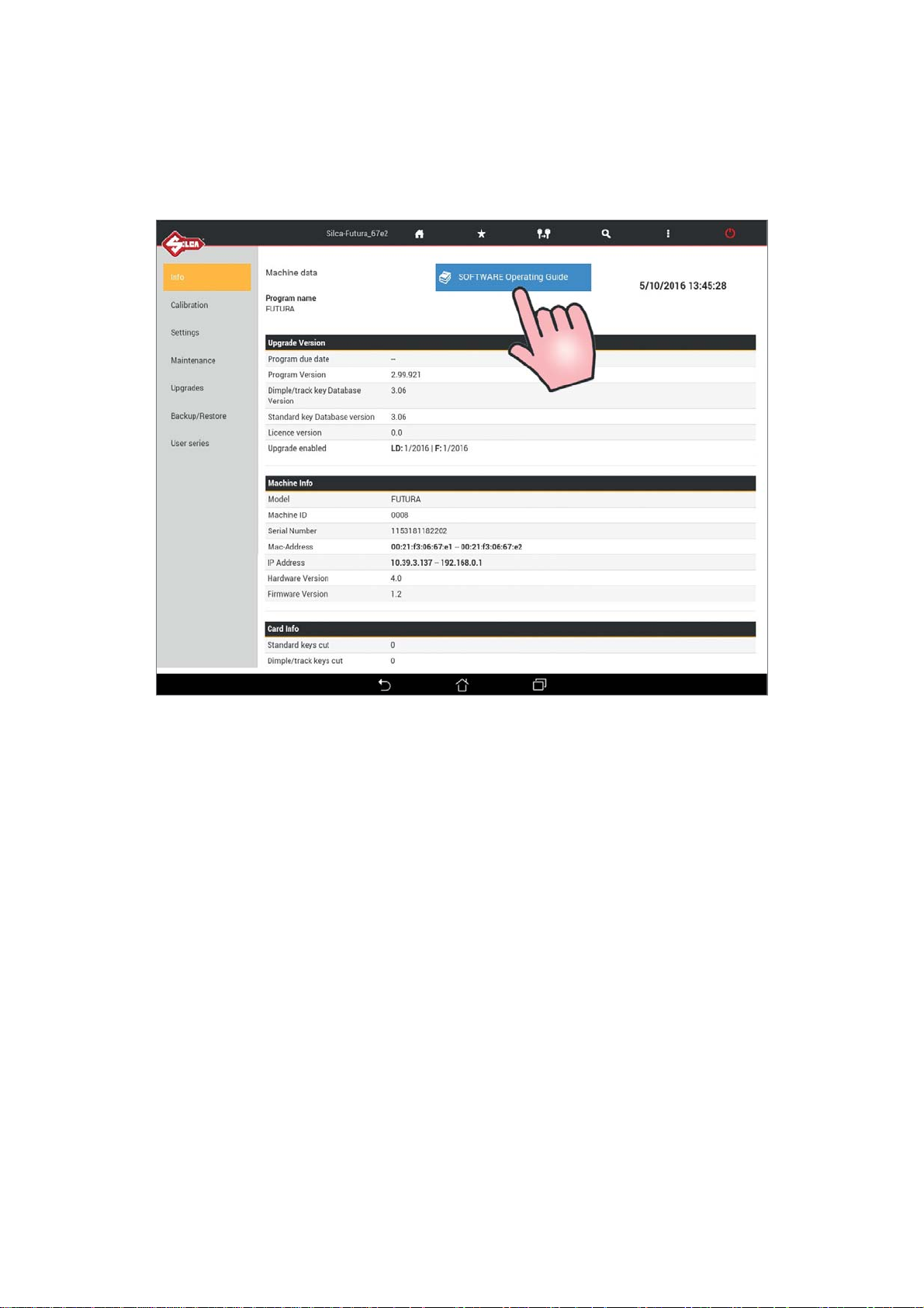
10 SOFTWARE OPERATING GUIDE
The FUTURA PRO SOFTWARE OPERATING GUIDE is on the Tablet.
Go to the “Options” > “Info” menu and tap on the appropriate icon (Fig. 81).
Fig. 83
38
Copyright Silca 2018
Page 43
Operating manual FUTURA PRO
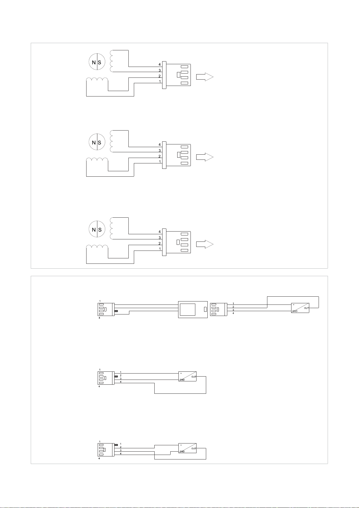
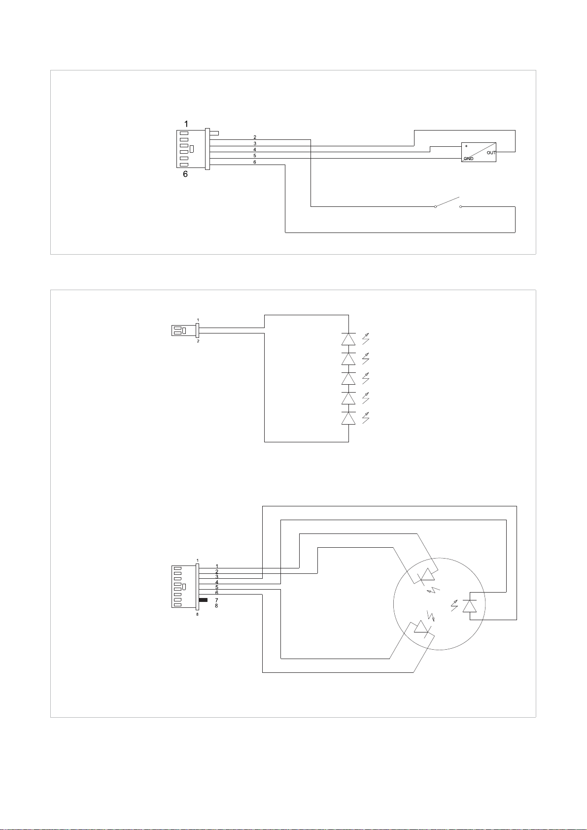
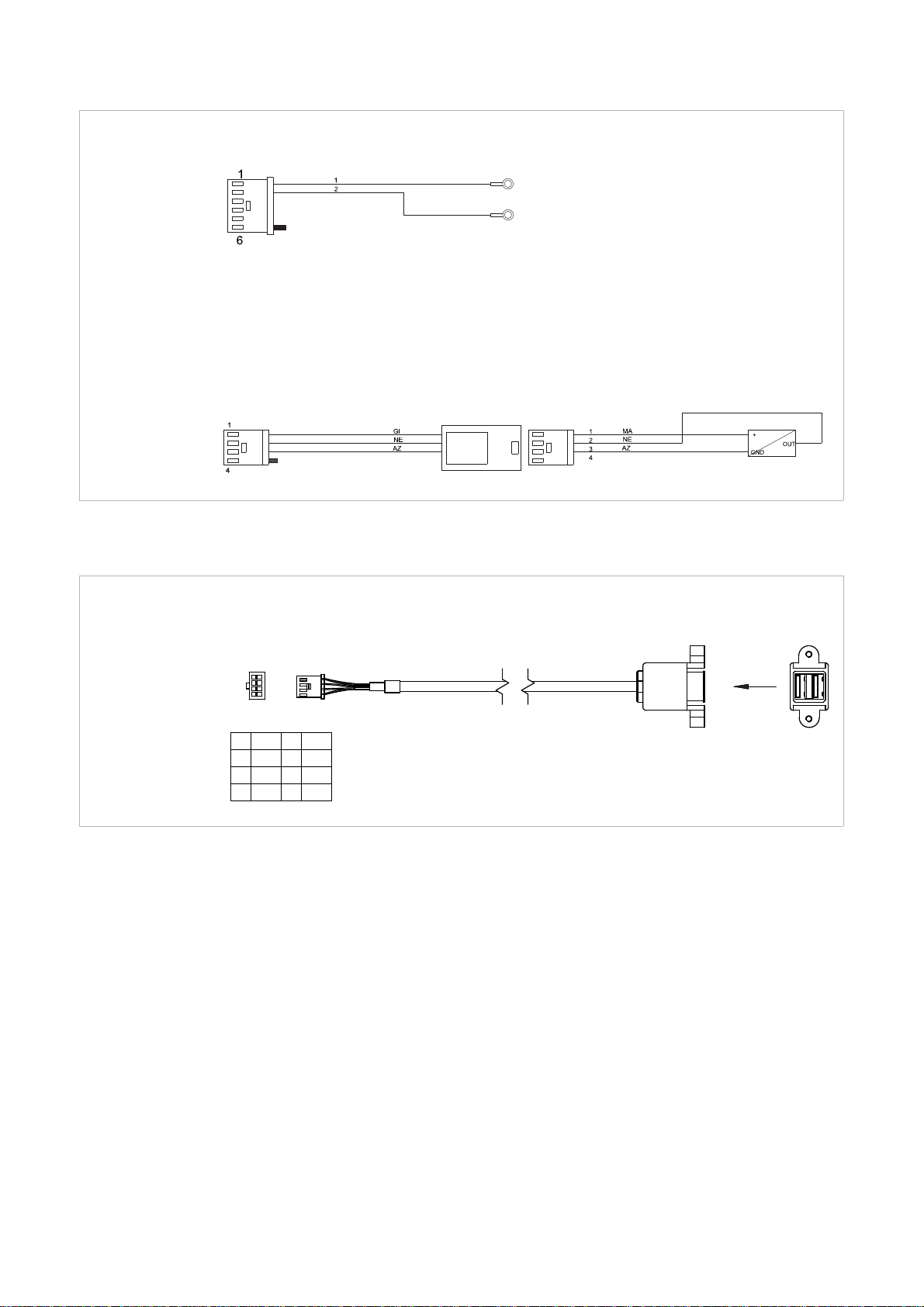
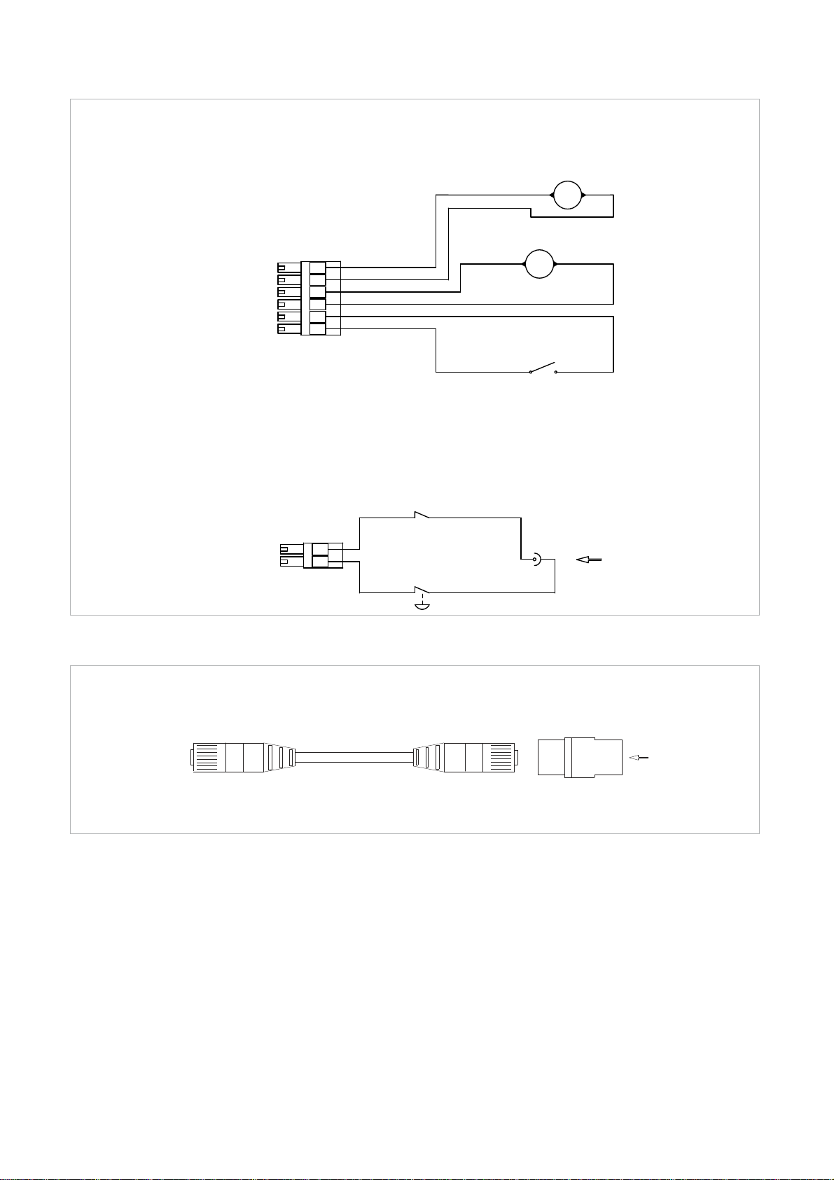
11 ELECTRICAL DIAGRAMS
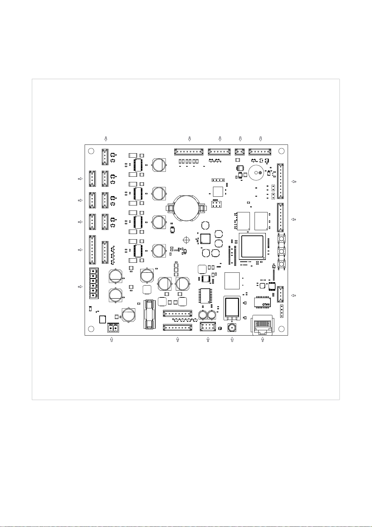
J22 micro carter
+ tracer point sensor
J9 optic reader
J13 X axis motor
J12 X axis sensor
J14 Y axis motor
J15 Y axis sensor
J10 gauge sensor
J8 led lamp RGB
J21 electric contact
J2 led lamp
J18 Z axis motor
J17 Z axis sensor
J19 not used
J16 not used
J7 cutter motors
+ micro carter
J4 power supply +24V
J23 not used
J20 not used
J6 antenna
J1005 USB ports
J1006
n.2 CANopen
J1007 RS232
J3 ethernet port
Copyright Silca 2018
39
Page 44
Operating manual FUTURA PRO
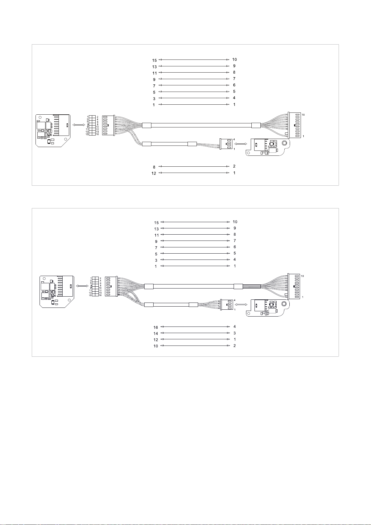
OPTIC READER
(1st version)
MOTHER
BOARD J9
Laser receiver
Laser transmitter
Laser receiver
OPTIC READER
(2nd version)
MOTHER
BOARD J9
Laser transmitter
40
Copyright Silca 2018
Page 45
Operating manual FUTURA PRO
STEP MOTOR X AXIS
red
light blue
green
yellow
red
white/red
green
white/green
MOTHER BOARD J13
STEP MOTOR Y AXIS
MOTHER BOARD J14
MOTHER BOARD J12
MOTHER BOARD J15
red
white/red
green
white/green
brown
light blue
black
yellow
black
light blue
Y AXIS SENSOR
STEP MOTOR Z AXIS
MOTHER BOARD J18
brown
black
light blue
X AXIS SENSOR
MOTHER BOARD J17
brown
black
light blue
Z AXIS SENSOR
Copyright Silca 2018
41
Page 46
Operating manual FUTURA PRO
TRACER POINT SENSOR
black
MOTHER BOARD J22
MOTHER BOARD J2
black
red
brown
light blue
MICRO CARTER
LED LAMP
MOTHER BOARD J8
green
brown
red
black
light blue
light blue
LED LAMP RGB
red
green
blue
42
Copyright Silca 2018
Page 47
Operating manual FUTURA PRO
ELECTRIC CONTACT
MOTHER BOARD J21
GAUGE SENSOR
MOTHER BOARD J10
MOTHER BOARD J1005
2
1
4
3
6
5
8
7
+5V 2 +5V
1
3
5 D+ 6 -
7 GND 8 GND
4 -
D-
USB PORTS
A
VIEW A
Copyright Silca 2018
43
Page 48
Operating manual FUTURA PRO
CUTTER MOTOR
+ MICRO CARTER
MOTHER BOARD J7
MOTHER BOARD J4
+ -
M
Cutter
motor
laser
1
6
1
2
3
4
5
6
red
black
red
black
black
black
+ -
M
Cutter
motor
flat
Micro
carter
POWER SUPPLY
24V
red
1
2
black
red
+/-
+24V
black
MOTHER
BOARD J3
ETHERNET PORT
ETHERNET
CABLE
ETHERNET CABLE EXTENSION
44
Copyright Silca 2018
Page 49

Operating manual FUTURA PRO
EN
J2
J3
J4
J6
J7
J8
J9
J10
J12
J13
J14
J15
Led lamp lampada led Led Lampe Lampe Led Lampara Led Lâmpada Led Led lamp
Ethernet port Porta ethernet
Power feeder
+24V
Antenna Antenna Antenne Antenne Antena Antena Antenne
Cutter motor
+ micro carter
Led lamp RGB
Optic reader Lettore ottico Opticher Leser
Gauge sensor Sensore calibro Lehre-Fühler
X axis sensor Sensore asse X Fuhler X-Achse Senseur axe X Detector eje X Sensor eixo X X-as sensor
X axis motor Motore asse X Motor X-Achse Moteur axe X Motor eje X Motor eixo X X-as motor
Y axis motor Motore asse Y Motor Y-Achse Moteur axe Y Motor eje Y Motor eixo Y Y-as motor
Y axis sensor Sensore asse Y Fuhler Y-Achse Senseur axe Y Detector eje Y Sensor eixo Y Y-as sensor
IT DE FR ES PT NL
Alimentatore
+24V
Motore fresa
+ micro carter
Lampada Led
RGB
Ethernet-
Anschluss
Speisegerat
+24V
Motor-Fräser
+ Mikro-Carter
Led Lampe RGB
Port Ethernet Puerto ethernet Porta ethernet Ethernetpoort
Alimentateur
+24V
Moteur fraise
+ micro carter
Lampe Led
RGB
Lecteur
optique
Senseur
calibre
Alimentador
+24V
Motor fresa
+ micro carter
Lámpara Led
RGB
Lector optico Leitor optico Optische lezer
Detector calibre Sensor calibre Gauge sensor
Alimentador
+24V
Motor fresa
+ micro carter
Lâmpada Led
RGB
Voedingseenheid
+24V
Freesmotor
+ cover micro
Led lamp
RGB
J16
J17
J18
J19
J20
J21
J22
tracer point sensor
J23
J1005
J1006
J1007
not used non usato nicht verwendet non utilisé no utilizado não utilizado niet gebruikt
Z axis sensor Sensore asse Z Fuhler Z-Achse Senseur axe Z Detector eje Z Sensor eixo Z Z-as sensor
Z axis motor Motore asse Z Motor Z-Achse Moteur axe Z Motor eje Z Motor eixo Z Z-as motor
not used non usato nicht verwendet non utilisé no utilizado não utilizado niet gebruikt
not used non usato nicht verwendet non utilisé no utilizado não utilizado niet gebruikt
Electric
contact
Micro cover +
not used non usato nicht verwendet non utilisé no utilizado não utilizado niet gebruikt
USB ports Porte USB USB-Anschlüsse Ports USB Puertos USB Portas USB USB-poorten
n.2 CANopen n.2 CANopen n.2 CANopen n.2 CANopen n.2 CANopen n.2 CANopen n.2 CANopen
RS232 RS232 RS232 RS232 RS232 RS232 RS232
Contatto
elettrico
Micro carter +
sensore tastatore
Elektrische
Kontakt
Mikro Carter +
Taster Fühler
Contact
électrique
Micro carter +
senseur palpador
Contacto
eléctrico
Micro carter +
sensor palpador
Contato
elétrico
Micro carter +
sensor palpador
Elektrisch
contact
Cover micro +
sensor tracer punt
Copyright Silca 2018
45
Page 50
EU DECLARATION OF MACHINE COMPLIANCE
SILCA S.p.A. - VIA PODGORA 20 ( Z.I.)
31029 VITTORIO VENETO (TV) - (ITALY)
TEL. 0438 9136 - FAX. 0438 913800
Declares under its own responsibility that the Key-cutting machine model
FUTURA PRO Serial Number ___________________________________
complies with the requirements of the following European Directives:
European Union DIRECTIVE 2006/42/EC (Machines)
European Union DIRECTIVE 2014/30/EU (Electromagnetic Compatibility)
European Union DIRECTIVE 2014/53/EU (RED)
European Union DIRECTIVE 2014/35/EU (Low Voltage) | 16 |
and with the
EN 55032:2015
EN 55022:2010 ETSI EN 300 328:2015 (V1.9.1)
EN 55024:2010 EN 60825-1:2014
EN 61000-3-2:2014 EN 62471:2015
EN 61000-3-3:2008 EN 60950-1:2006 + A11:2009 + A1:2010 + A12:2011+A2:2013
EN 301 489-1:2011 (V1.9.2) EN ISO 12100:2010
EN 301 489-17:2012 (V2.2.1) EN 62233:2008
Standards
Maurizio Ugel of the Silca S.p.A. Research & Development Division is authorized to create a Technical
File.
VITTORIO VENETO 26/10/2016
General Manager Basic Production Center
Page 51

SILCA S.p.A.
Via Podgora, 20 (Z.I.)
31029 VITTORIO VENETO (TV)
Phone: +39 0438 9136
Fax +39 0438 913800
E-mail: [email protected]
www.silca.biz
United Kingdom
SILCA Ltd.
Unit 6 Lloyds Court - Manor Royal
CRAWLEY RH10 9QU
Phone: +44 1293 531134
Fax +44 1293 531108
E-mail: [email protected]
www.silcaltd.co.uk
France
SILCA S.A.S.
12, Rue de Rouen
Z.I. de Limay - Porcheville
78440 PORCHEVILLE
Phone: +33 1 30983500
Fax +33 1 30983501
E-mail: [email protected]
www.silca.fr
Germany
SILCA GmbH
Siemensstrasse, 33
42551 VELBERT
Phone: +49 2051 2710
Fax +49 2051 271172
E-mail: [email protected]
www.silca.de
India
MINDA SILCA Engineering Ltd.
Plot no.37, Toy City,
GREATER NOIDA (U.P.) - 201308
Phone: +91 9871397630/31
Fax: +91 120 2351301
E-mail: [email protected]
www.mindasilca.in
North America
U.S.A., Canada, Caribbean Islands
KABA Ilco Corp.
400 Jeffreys Road
Rocky Mount, NC 27804 USA
Phone: 1 800 334 1381 / 1 252 446 3321
Fax: 1 252 446 4702
E-mail: [email protected]
www.ilco.us
Central America
Mexico, Guatemala, Belize, El Salvador,
Honduras, Nicaragua, Costa Rica, Panama
Corporación Cerraiera Alba S.A. de C.V.
Prolongaci
Col.Los reyes, Tultitlán, Estado de México C.P. 54915
ón avenida independencia 14, Bodega 5,
E-mail: [email protected]
Kaba Mexico
Phone: 01 55 5366 7200
www.kabamexico.com
Spain
SILCA KEY SYSTEMS S.A.
C/Santander 73A
08020 BARCELONA
Phone: +34 93 4981400
Fax +34 93 2788004
E-mail: [email protected]
www.silca.es
Netherlands
H. CILLEKENS B.V.
Metaalweg, 4
6045 JB ROERMOND
Phone: +31 475 325147
Fax +31 475 323640
E-mail: [email protected]
www.hcillekens.nl
Brazil
KABA DO BRASIL Ltda
Rua Guilherme Asbahr Neto, 510
São Paulo, SP 04646-001
Phone: +55 11 55454520 / 29
E-mail: [email protected]
www.silcachaves.com.br
Colombia
SILCA SOUTH AMERICA S.A.
Km 1.5 Via Briceño-Zipaquira
Parque Ind. Trafalgar Bodega 3
Tocancipa-Cundinamarca
Phone: +57 1 7366480
Fax +57 1 7366490
www.fl exonsilca.co
 Loading...