

Page 1

Fastbit
Operating Manual
Original Instructions
D444087XA
vers. 1.0
EN
Page 2

© 2014 SILCA S.p.A - Vittorio Veneto
This manual has been drawn up by SILCA S.p.A.
All rights reserved. No part of this publication may be reproduced or used in any form or by any means
(photocopying, microfi lm or other) without the written permission of SILCA S.p.A.
Edition: October 2014
Printed in India
by MINDA SILCA Engineering Ltd.
Plot no.37, Toy City, GREATER NOIDA (U.P.) - 201308
The Manufacturer declines any responsibility for possible inaccuracies in this document due to printing or transcription errors.
The Manufacturer reserves the right to alter the information without prior notice, except when they affect safety. This document or any of its parts
cannot be copied, altered or reproduced without written authorization from the Manufacturer. Keep the manual and look after it for the entire life
cycle of the machine.
The information has been drawn up by the manufacturer in his own language (Italian) to provide users with the necessary indications to use the
key-cutting machine independently, economically and safely.
IMPORTANT NOTE: in compliance with current regulations relating to industrial property, we hereby state that the
trade-marks or trade names mentioned in our documentation are the exclusive property of authorized
manufacturers of locks and users.
Said trade-marks or trade names are nominated only for the purposes of information so that any lock for which our
keys are made can be rapidly identifi ed.
Page 3

INDEX
USE OF THE MANUAL .......................................................................................................................1
GENERAL WARNINGS .......................................................................................................................3
1 MACHINE DESCRIPTION ....................................................................................................................4
1.1 Main working parts ......................................................................................................................6
1.2 Technical Data ............................................................................................................................7
1.3 Electric circuit ..............................................................................................................................7
1.4 Accessories provided ..................................................................................................................8
2 TRANSPORT ........................................................................................................................................9
2.1 Packing .......................................................................................................................................9
2.2 Unpacking ...................................................................................................................................9
2.3 Handling the machine .................................................................................................................9
3 MACHINE INSTALLATION AND PREPARATION ..............................................................................10
3.1 Checking for damage ................................................................................................................10
3.2 Environmental conditions ..........................................................................................................10
3.3 Positioning ...............................................................................................................................10
3.4 Description of work station .......................................................................................................10
3.5 Separate parts ..........................................................................................................................11
3.5.1 Carriage handle...............................................................................................................11
3.5.2 Power cable ....................................................................................................................11
3.5.3 Fixing bracket ..................................................................................................................12
3.6 Connection to the mains ...........................................................................................................12
4 MACHINE REGULATION AND UTILIZATION ....................................................................................13
4.1 Micrometric tracer point ............................................................................................................13
4.2 Tracer point spring ....................................................................................................................13
4.3 Checking and calibration ...........................................................................................................13
4.4 Calibration .................................................................................................................................13
5 CUTTING OPERATIONS ..................................................................................................................16
5.1 Tilting carriage for rounding off key cuts ...................................................................................16
5.2 Cutting bit and double bit keys ..................................................................................................17
5.3 Cutting keys with central stop ...................................................................................................19
5.4 Cutting short double bit keys .....................................................................................................20
5.5 Cutting pump keys ....................................................................................................................21
6 MAINTENANCE ..................................................................................................................................22
6.1 Replacing the brush ..................................................................................................................22
6.2 Replacing the cutting tool ..........................................................................................................23
6.3 Replacing the tracer point .........................................................................................................24
6.4 Replacing the fuses ..................................................................................................................24
6.5 Access to the lower compartment .............................................................................................25
6.6 Replacing the main switch ........................................................................................................25
6.7 Replacing the motor ..................................................................................................................26
6.8 Replacing and/or adjusting tension on the belt .........................................................................27
6.9 Replacing the motor on switch .................................................................................................28
6.10 Replacing the condenser ..........................................................................................................28
7 DISPOSING OF MACHINE ................................................................................................................29
8 ASSISTANCE .....................................................................................................................................30
8.1 How to request service .............................................................................................................30
Page 4

Page 5
Operating manual FASTBIT
USE OF THE MANUAL
This manual has been drawn up by the Manufacturer and is an integral part of the machine literature. The manual
gives information it is obligatory for the operator to know and which makes it possible to use the machine safely.
User’s Manual
This user’s manual is provided because it is essential for proper use and maintenance of the machine. The
manual must be kept carefully throughout the life of the machine, including the decommissioning stage. Keep in
a dry place close to the machine where it is always to hand for the operator.
ATTENTION: IT IS OBLIGATORY to read the manual carefully before using the machine.
Readers’ characteristics
This manual must be read and its contents acquired by those who will use it.
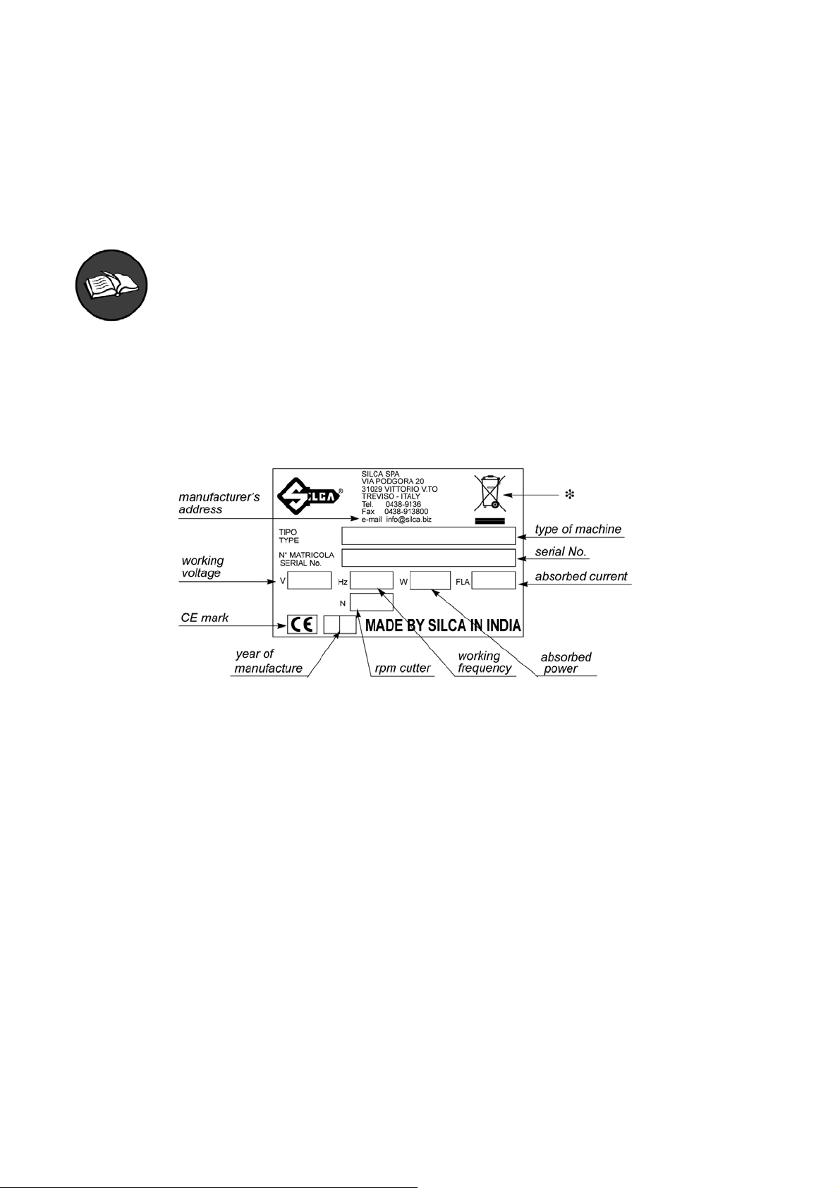
Manufacturer’s ID
FASTBIT has an ID plate located on the right side of the machine, showing the serial number.
Fig. 1
(*) see chap. 7 DISPOSING OF MACHINE.
How to apply for after-sales service
Silca provides purchasers of FASTBIT with After-Sales Service. For the total safety of the operator and machine,
any operation not described in the manual must be carried out by the manufacturer or in the special Service
Centres recommended by Silca.
At the end of the manual there is a list of manufacturers’ and authorized Service Centre addresses.
The warranty card attached to the machine covers free repairs or replacement of faulty parts for 24 months from
the date of purchase*.
All operations must be agreed by the user with Silca or the Service Centre.
* Damage caused by negligence or wrong use of the machine by the user will null the warranty.
Copyright Silca 2014
1
Page 6
Operating manual FASTBIT
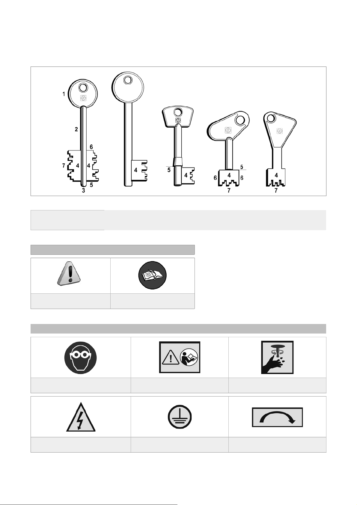
TERMINOLOGY
Per coloro che mancano di esperienza in materia di chiavi e cifratura, ecco un’illustrazione dei termini più frequenti
utilizzati:
Fig. 2
1) Head
2) Stem
3) Tip
4) Bit
5) Stop
6) Side
GRAPHICS IN THE USER’S MANUAL
Pay attention Obligation to read the manual
GRAPHICS ON THE FASTBIT MACHINE
Obligatory use of safety goggles Read instructions before use
7) Cuts
WARNING!
cutting tool in motion
WARNING!
presence of electric power
2
Earth connection Cutter rotation direction
Copyright Silca 2014
Page 7

Operating manual FASTBIT
GENERAL WARNINGS
FASTBIT is designed to the principles of European Standards (CE). Right from the design stage solutions
have been adopted to eliminate hazards for the operator in all the stages of use: handling, regulation, use and
maintenance.
The materials used in manufacture and the components employed in using FASTBIT are not dangerous and
ensure that the machine complies to current standards.
Silca S.p.A. has also experimented and applied numerous technical solutions that allow the key-cutting machine
to optimize the quality of the cut keys.
To guarantee maintaining these results over time, please follow the instructions below:
• Observe the procedures described in this manual;
• Always use Original Silca Tools as they are designed to make the best of FASTBIT and provide quality
key-cutting;
• Use Silca key blanks, made with top quality materials;
• Have the key-cutting machine checked periodically by an authorized Silca After-Sales Service Centre
(list at the end of this manual);
• Always use Silca Original Spare Parts. Beware of imitations!
NORMAL USE
FASTBIT is a key-cutting machine and must be installed and used according to the rules and specifi cations
established by the manufacturer.
Any other use different from that indicated in this manual will cause the forfeiture of all customers’ rights to make
claims on Silca S.p.A. and may be an unknown source of hazard for the operator or third parties.
ATTENTION: negligent use or failure by the operator to observe the instructions in this manual are
not covered by the warranty and the manufacturer declines any responsibility in such cases.
SAFETY
The key-cutting machine is built entirely to standards. The operations for which it has been designed are
easily carried out at no risk to the operator.
The adoption of general safety precautions (wearing protective goggles) and observation of the instructions
provided by the manufacturer in this manual eliminate all human error, unless deliberate.
The key-cutting machine is designed with features which make it completely safe in all its parts.
• Cutter motor protection
A TTENTION: the cutter motor is protected from overheating by a device (inside the motor) that stops
it when it reaches a dangerous temperature.
This condition can occur when the machine motor is left on continuously, with high ambient temperatures or
in severe working conditions. If the cutter motor overheats it cuts out automatically. In such cases proceed as
follows:
a) turn off the master switch (H).
b) let the motor cool for at least 2 hours then use the machine normally.
RESIDUAL RISKS
There are no further risks arising from the use of the machine.
SAFETY REGULATIONS
• Always disconnect the machine when it is not in use or when performing maintenance operations.
• Check the electrical wiring periodically; replace any wires that show signs of wear.
• Always work with dry hands free of grease or oil.
• Never pull hard on the power lead and make sure it does not come into contract with oil, sharp objects or heat.
Never remove the earth wire from the plug. Make sure the earth wire connection is sound.
• Do not use the machine in dangerous environments (wet or damp).
• All visitors, especially children, must stay at a safe distance from the machine and must never come into
contact with the electric wiring.
Copyright Silca 2014
3
Page 8
Operating manual FASTBIT
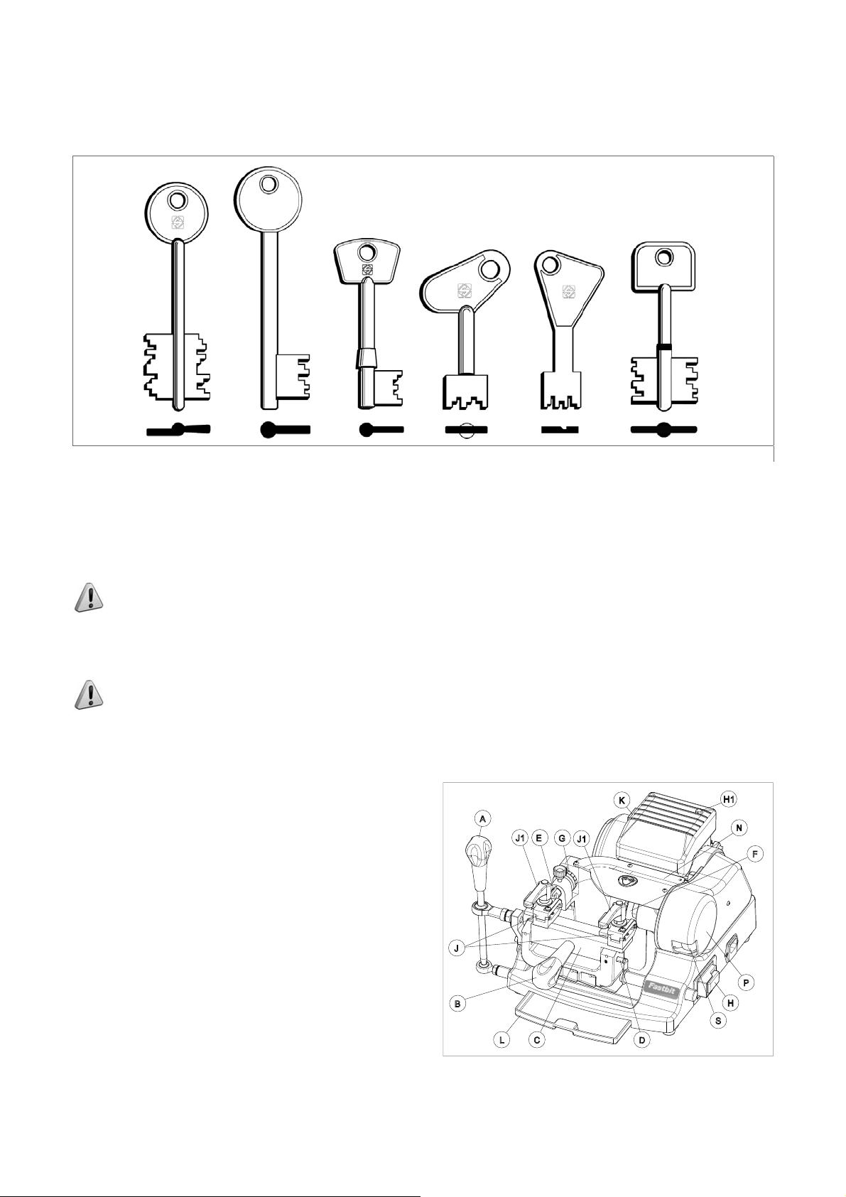
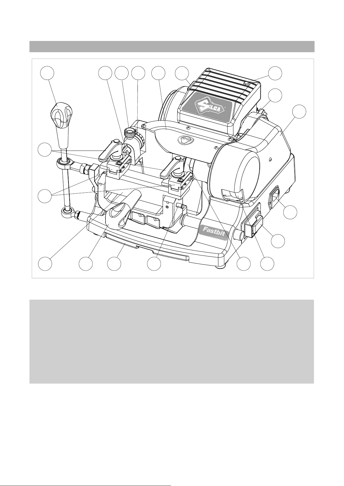
1 MACHINE DESCRIPTION
FASTBIT is a professional key-cutting machine for bit, double bit, pump keys, mail box keys and special keys.
Fig. 3
The main parts of the machine are described below:
• Main switch
The key-cutting machine is connected to a power socket provided with a differential switch; when the machine
is turned on by means of the switch (H) located on its right-hand side, the warning light (H1) comes on to show
that the machine is live.
ATTENTION: switch (H) is electromagnetic, in the event of a power failure it goes out automatically.
When electricity is restored it must be reset manually to power the machine again by means of the
plug.
• Motor start-up switch
On the left-hand side of the motor there is the motor start switch (K).
ATTENTION: the illuminated switch remains on to indicate that the key-cutting machine has been
started (cutter in motion).
• Motor and transmission unit
Motor transmission takes place by belt. On the right-hand side of the motor there is the transmission shaft which
moves the cutting tool (F) and the brush (S). These components are protected by:
-
cutting tool cover (N)
-
brush cover (P)
• Clamp carriages
The horizontal carriage (C) controlled by lever (A) has a
handle (B) for front movement and holds 2 clamps (J).
The carriage is so designed as to avoid accumulation of
dust or cutting swarf.
The machine is designed with a ramp along which
chippings can fall into the special chippings tray (L) placed
under the carriage and easily removable for emptying and
cleaning.
K
A
J1
E
G
J1
J
B
C
L
D
H1
N
F
P
H
S
Fig. 4
4
Copyright Silca 2014
Page 9
Operating manual FASTBIT
• Cutting unit
The cutting unit contains the actual working parts of the FASTBIT key-cutting machine, which operate together to
cut and fi nish keys “read” from the originals. The working parts are described below.
• Cutting Tool
The cutting tool (F) is the part of the FASTBIT used for cutting key blanks. The cutting tool is in HSS super rapid
steel and is protected by a special cover (N) to ensure safe operation.
• Micrometric tracer point
The tracer point (E) dedicated to reading the cuts on keys to be copied is housed on the left-hand side of the
machine. Depth is easily regulated by means of the relevant centesimal ring nut (G).
• Clamp knobs
The clamps are locked by two anatomical handles (J1), which ensure perfect grip on the keys with only slight
locking pressure.
• Brush
The brush (S) is used to eliminate burrs from the cuts and is made of non-abrasive material. Press the motor start
switch (K) to activate the brush.
• Clamps
The clamps (J) comprise two jaws which ensure perfect hold on the shafts of bit/double bit and pump keys.
Fig. 5
Copyright Silca 2014
5
Page 10
Operating manual FASTBIT
1.1 Main working parts
A
J1
E E1
G
N
K
H1
M
P
J
R
H
C
A - carriage movement lever
B - carriage handle
C - clamp carriage
D - carriage release pin (tilting)
E - tracer point
E1 - tracer point spring locking knob
F - cutting tool
G - tracer point ring nut
H - main switch
H1 - warning light (power)
B
L
D
Fig. 6
J - clamp
J1 - clamp handle
K - motor start switch
L - swarf tray
M - motor
N - cutting tool cover
P - brush/belt cover
R - power supply socket
S - brush
F
S
6
Copyright Silca 2014
Page 11
Operating manual FASTBIT
1.2 Technical Data
Power supply: 230V - 50/60Hz
Maximum absorbed power: 230V: 2 Amp. 180 Watt
Cutter motor: single phase and speed
Movements: by ball joint on rectifi ed carriage
Cutter: in Acciaio Super Rapido (HSS)
Tool speed: 50Hz: 600 rpm
60Hz: 720 rpm
Runs (maximum length of cuts): 42 mm
Dimensions: width: 400 mm - depth: 460 mm - height: 300 mm
Mass: Kg. 15.4
Noise level: sound pressure Lp(A) = less than 70 dB(A)
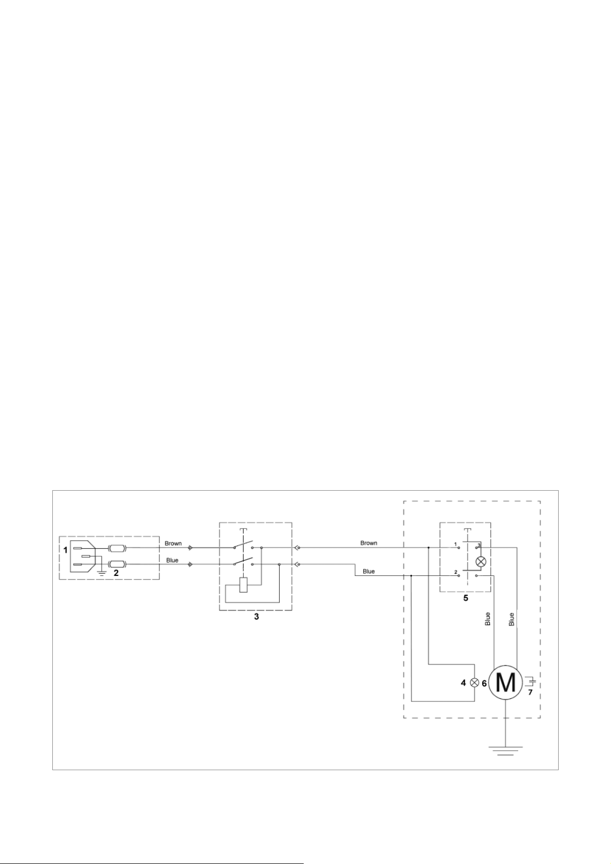
1.3 Electric circuit
The main parts of the electric circuit on the key-cutting machine are listed below:
1) Power supply socket
2) Fuses 4 Amp rapid (230V)
3) Master switch
4) LED
5) Motor start switch
6) Motor with collector: 230V-50/60Hz
7) Condenser
Fig. 7
Copyright Silca 2014
7
Page 12

Operating manual FASTBIT
1.4 Accessories provided
FASTBIT comes with a set of accessories for its operation and maintenance (tools, hex wrenches, fuses) supplied
in a special tool kit comprising:
allen key 2,5 mm fuses 4 Amp rapid (230V)
allen key 3 mm cutter release rod
allen key 4 mm
spanner 19 mm
adjusting pins (2 pcs)
Separately:
fi xing bracket
8
Copyright Silca 2014
Page 13

Operating manual FASTBIT
2 TRANSPORT
The FASTBIT key-cutting machine is easily transported and is not dangerous to handle.
The packed machine can be carried by one person.
2.1 Packing
The FASTBIT is packed in a strong cardboard box, the dimensions of which are shown in Fig. 8, suffi ciently
robust to be used for storing the machine for long periods.
Inside the box the machine is enclosed in two expanded polymer shells. The shells and cardboard box ensure
safe transportation and protect the machine and all its parts.
Fig. 8
Keep dry Handle with care This side up
NOTE:
prevent sudden movements or rough handling from damaging the machine, persons or things.
to avoid damaging the key-cutting machine it must always be transported in its packing case. This will
2.2 Unpacking
To remove the machine from the packing box:
1) Cut the straps with scissors and remove,
2) Open the box without damaging it as it may be used again (e.g. removals, dispatch to the manufacturers for
repairs or servicing),
3) Check the contents of the box, which should comprise:
- 1 FASTBIT key-cutting machine packed in a protective shell;
- 1 set of documents, including: operating manual, spare parts list and guarantee;
- 1 carriage handle;
- 1 power cable
- 1 tool set;
4) Remove the key-cutting machine from the protective shell.
2.3 Handling the machine
When the FASTBIT has been unpacked, place it directly on its workbench.
This operation can be carried out by one person.
ATTENTION: fi rmly holding the base, and no other part, to lift and carry the machine
Copyright Silca 2014
.
9
Page 14

Operating manual FASTBIT
3 MACHINE INSTALLATION AND PREPARATION
The FASTBIT key-cutting machine can be installed by the purchaser and does not require any special skills.
However, some checks and preparation for use need to be carried out by the operator.
3.1 Checking for damage
The FASTBIT key-cutting machine is solid and compact and will not normally damage if transport, unpacking and
installation have all been carried out according to the instructions in this manual.
However, it is always advisable to check that the machine has not suffered any damage.
3.2 Environmental conditions
To ensure that the best use is made of the FASTBIT key-cutting machine, certain parameters must be borne in
mind: damp, badly ventilated sites should be avoided.
The ideal conditions for the machine are:
- temperature: between 10°C and 40°C; relative humidity: 60% circa; room illumination: approximately 500 Lux.
3.3 Positioning
1) Place the key-cutting machine on a horizontal surface, solid
enough to take the weight (15.4 Kg).
- to work with ease, we suggest that the workbench be
approximately the height of the operator’s hip.
- it is important to leave clearance of at least 30 cm behind
the machine and on each side to ensure proper ventilation
(Fig. 9).
2) Ensure that the machines voltage is the same as that of the
mains power supply, which must be properly earthed and
provided with a differential switch.
3) Connect the power supply cable to the power supply socket.
Fig. 9
3.4 Description of work station
The key-cutting machine needs only one operator, who has the following controls at his/her disposal (Fig. 6):
• Main switch (H)
• Motor start switch (K)
• Carriage movement lever (A)
• Carriage handle (B)
• Clamps (J)
• Clamps handles (J1)
• Carriage release pin (D)
K
A
J1
E
G
J1
J
B
L
C
D
H1
N
P
H
S
F
10
Fig. 10
Copyright Silca 2014
Page 15

Operating manual FASTBIT
3.5 Separate parts
The separately packed parts must be installed on the FASTBIT key-cutting machine by the purchaser , as follows:
3.5.1 Carriage handle
Screw the handle (B) onto the carriage lever (Fig. 11).
B
Fig. 11
3.5.2 Power cable
Connect the key-cutting machine power cable to the electricity mains (Fig. 12).
Fig. 12
Copyright Silca 2014
11
Page 16

Operating manual FASTBIT
3.5.3 Fixing bracket
The key-cutting machine can be fi xed to the work bench with the bracket provided. Follow the instructions below:
1) Turn off the machine and unplug from the mains.
2) Remove the two front feet.
3) Place the bracket as indicated in.
4) Screw the two feet into the bracket.
Fig. 13
3.6 Connection to the mains
For the safety of the operator and the machine it is important to ensure that the machine is connected to the
proper mains voltage by means of an earthed differential switch.
12
Copyright Silca 2014
Page 17

E1
E1
G
G1
Operating manual FASTBIT
4 MACHINE REGULATION AND UTILIZATION
4.1 Micrometric tracer point
The use of a micrometric tracer point on a machine for cutting bit and pump keys not only provides perfect fast
readings, but also rapidly resolves all those small depth variations needed when worn keys are involved.
NOTE: when the 2 ring nuts are turned together the movement for each notch equals 0.05 mm (with
knob (E1) loosened).
4.2 Tracer point spring
The spring function facilitates the search for spaces with the tracer point before the cutter makes the cuts.
• To enable the tracer point spring:
simply loosen the knob (E1) by a few turns (Fig. 14).
• To disable the tracer point spring:
push the tracer point all the way until it stops, then lock with the knob (E1).
Tracer point spring ENABLED Tracer point spring DISABLED
Fig. 14
4.3 Checking and calibration
The cutting tool on the machine is the part used to cut the key blanks and should be periodically checked and
replaced, if necessary.
Every time the cutting tool is changed, and during periodical operational tests, check calibration.
4.4 Calibration
The FASTBIT key-cutting machine requires two types of calibration: axis and depth.
Axis calibration:
Axis calibration is used to adjust the cutting space on the key.
The axis setting for the FASTBIT is fi xed and is established on assembly in our workshops.
Fig. 15
Copyright Silca 2014
13
Page 18

Operating manual FASTBIT
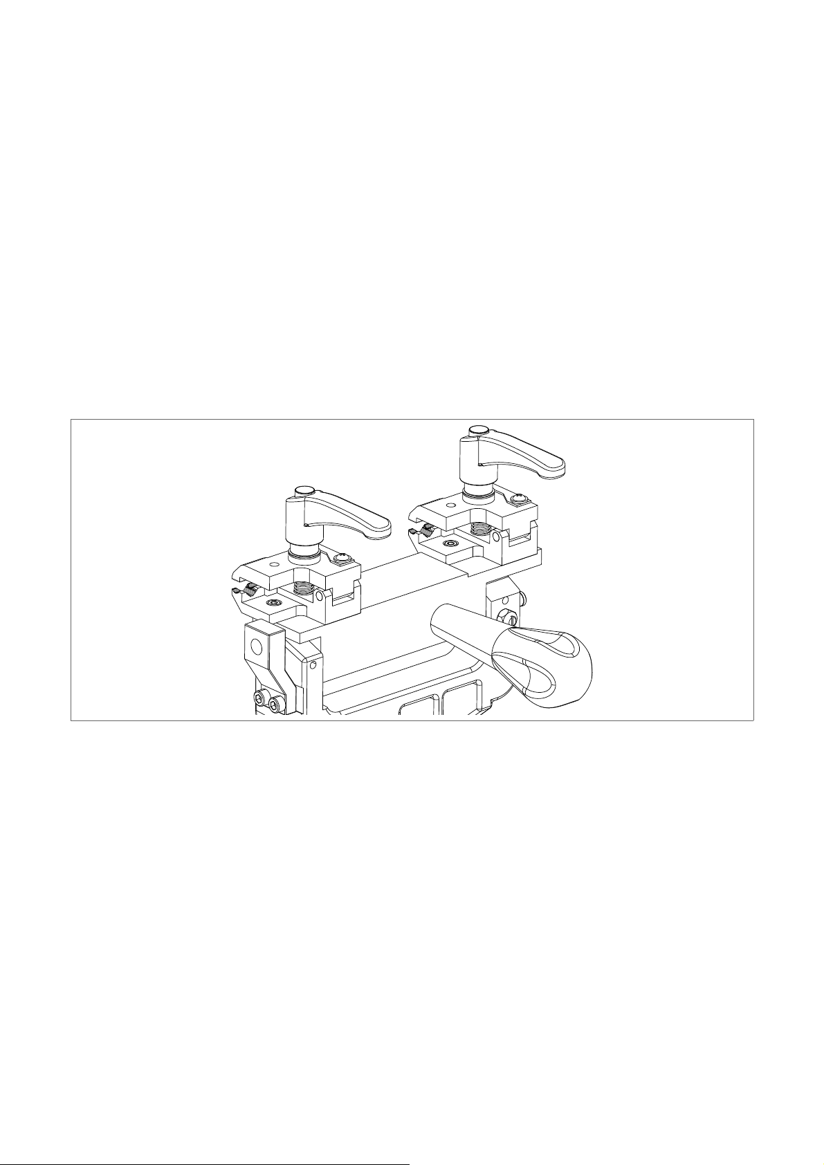
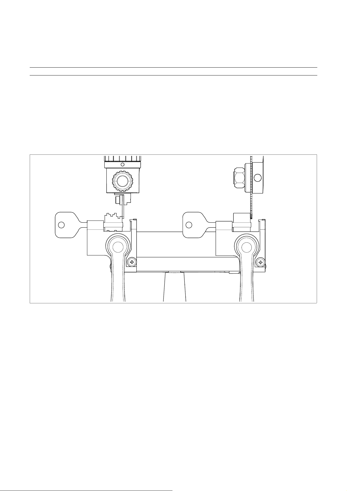
Axis calibration control:
1) Turn off the machine and unplug.
NOTE: check that the carriage is locked into the fi xed horizontal position (chap. 5.1).
2) Close the 2 clamps with their handles (J1).
3) Use the lever (A) to take the stops (Y) against the right-hand side of the tracer point and cutter.
The ideal condition is achieved when the internal part of the left-hand stop is up against the right-hand side of the
tracer point and the internal part of the right-hand stop is in contact with the right-hand side of the cutter.
If this condition is not achieved, contact Silca After-Sales Service.
Y
Y
Fig. 16
Depth calibration:
Depth calibration is regulation of the cutting depth (Fig. 15).
Proceed as follows:
1) Turn off the machine and unplug.
NOTE: check that the carriage is locked into the fi xed horizontal position (chap. 5.1).
2) Disable the tracer point spring (chap. 4.2).
3) Place the adjusting pins (provided) on the clamps.
4) Move the carriage and take the pins into contact with the tracer point and cutter (Fig. 17).
5) Turn the cutting tool manually in the opposite sense to the rotation and check that it skims the adjusting pin in
several places.
6) If necessary, regulate the cutting depth by means of the tracer point, as described:
7) Loosen knob (E1).
- turn the ring nuts (G) and (G1) clockwise to advance the tracer point (less deep cuts) (Fig. 18).
- turn the ring nuts (G) and (G1) anticlockwise to return (deeper cuts) (Fig. 19).
NOTE: when the 2 ring nuts are turned together the movement for each notch equals 0.05 mm (with
knob (E1) loosened).
8) Repeat these operations until the cutting tool skims the adjusting pin in several points.
14
Copyright Silca 2014
Page 19

Operating manual FASTBIT
G
E1
Fig. 17
Fig. 18
Turn the nut to the RIGHT (clockwise) to take the tracer point down. Result: LESS DEEP CUTS.
Fig. 19
• Turn the nut to the LEFT (anticlockwise) to take the tracer point up. Result: DEEPER CUTS.
.
Copyright Silca 2014
15
Page 20

Operating manual FASTBIT
5 CUTTING OPERATIONS
ATTENTION: for complete safety during the cutting operations, take the following precautions:
• Always work with dry hands.
• Check that the machine is properly earthed.
• Wear protective goggles even if the machine has a protective shield over the cutting tool.
• Start the motor (switch K) only after completing the operations on the carriage (securing the keys,
etc..).
• Keep hands away from the cutting tool in motion.
5.1 Tilting carriage for rounding off key cuts
The carriage can be given a tilting movement for rounding off cuts.
• To activate the tilting movement: pull out the pin (D) and move handle (B) to round off the cuts.
• To deactivate the tilting movement: fi t the pin (D) into its seat so that the carriage is locked in a fi xed
horizontal position.
D
B
Fig. 20 Fig. 21
B
16
Copyright Silca 2014
Page 21

Operating manual FASTBIT
5.2 Cutting bit and double bit keys
NOTE: check that the carriage is locked into the fi xed horizontal position (chap. 5.1).
1) Fit the keys into the clamps (original key in the left-hand clamp and key blank in the right-hand clamp) with the
bit up against the stop (Y) (Fig. 26).
2) Close the clamps with handles (J1) making sure that the key shafts are in the V groove and check that the key
bits are perpendicular to the tracer point and cutter (Fig. 24).
3) Activate the tilting carriage mechanism (chap. 5.1).
4) Turn on the machine with the switch (H).
5) Use the lever (A) to slowly take the carriage towards the cutter and press the switch (K) to start the motor.
6) Hold the handle (B) slightly raised with the key facing downwards.
7) Take the cut closest to the original key tip against the tracer point and lower the handle (B) to round off the cut.
8) Take the carriage back to come out of the cut. Move the carriage sideways and enter the next cut (Fig. 25). Do
not move sideways once into the cut.
9) Complete all the bits in the same way and remove any excess material at the end of the cutting operation
(towards the head).
10) Take the carriage all the way back.
11) Turn off the switch (K).
12) For double bit keys, turn both keys over and repeat the operations described above.
13) When cutting is fi nished, turn off the switch (K) and remove the keys.
Fig. 22
Fig. 23 Fig. 24 Fig. 25
Copyright Silca 2014
17
Page 22

Operating manual FASTBIT
Y
Fig. 26
Y
18
Fig. 27
Copyright Silca 2014
Page 23

Operating manual FASTBIT
5.3 Cutting keys with central stop
NOTE: check that the carriage is locked into the fi xed horizontal position (chap. 5.1).
1) Loosen the clamp handles slightly to allow the keys to enter.
2) Insert the original key into the left-hand clamp with the
central stop up against the clamp (left-hand side) and the
bit parallel to the clamp (Fig. 28); tighten the handle (J1) to
secure the key.
3) Insert the key to be cut into the right-hand clamp with the
central stop up against the clamp (left-hand side) and the
bit parallel to the clamp; tighten the handle (J1) to secure
the key.
4) Start the machine with switch (K) and proceed with cutting.
5) Move the carriage with lever (A) to take the original key
cuts into contact with the tracer point.
6) Pull the carriage back and go on to another cutting point,
then continue as for point 6.
7) When cutting is fi nished, turn off the switch (K) and remove
the keys.
J1
Fig. 28
Fig. 29
Copyright Silca 2014
19
Page 24
Operating manual FASTBIT
5.4 Cutting short double bit keys
When it is necessary to cut very short keys that do not reach the stop (Y), observe the fi gure and proceed as
follows.
NOTE: Check that the carriage is locked in the fi xed horizontal position (cap. 5.1).
1) Loosen the clamp handles by a couple of turns so that the key can be fi tted.
2) Fit the key to be cut into the right-hand clamp, lock the handle without blocking the key.
3) Fit the original key into the left-hand clamp; lock the handle without blocking the key.
4) Raise the carriage and place the key bits against the tracer point and cutter (Fig. 30).
5) Use the handles to block the keys so that they are both perfectly aligned.
6) Proceed with cutting; if necessary round off the cuts by activating the carriage rocking movement.
7) Use the knob to raise the carriage and take the original key into contact with the tracer point to make the cuts.
8) Use the knob to pull back the carriage and move into position for another cut, then continue as for point 6.
9) When cutting is fi nished turn off switch (K) and remove the keys.
20
Fig. 30
Copyright Silca 2014
Page 25

Operating manual FASTBIT
5.5 Cutting pump keys
ATTENTION: for some models (see Fig. 22).
NOTE: check that the carriage is locked into the fi xed horizontal position (chap. 5.1).
1) Place the original key in the left-hand clamp (J) with the bit up against the clamp (Fig. 32).
2) Use the special seats for pump keys: for keys with round shafts and Mottura type keys with square shafts (Fig.
31).
3) Fit the key blank into the right-hand clamp (J) in the same way.
4) Enable the tracer point spring (chap. 4.2).
5) Start the machine with switch (H) and proceed with cutting.
6) Use the lever (A) to slowly take the carriage towards the cutter and press the button (K) to start the motor.
7) Take the fi rst cut on the right of the original key against the tracer point and push the carriage all the way.
8) Take the carriage back to come out of the cut. Move the carriage sideways and enter the next cut. Do not move
sideways once into the cut.
9) Complete all the bits in the same way and if necessary check the sides of the bits.
10) When the cutting operation is fi nished, take the carriage all the way back.
11) Turn off the switch (K) and remove the keys
.
Fig. 31
Fig. 32
Copyright Silca 2014
21
Page 26

Operating manual FASTBIT
6 MAINTENANCE
ATTENTION: for repairs or replacement of parts for maintenance, the ‘CE’ mark is guaranteed only
if original spare parts provided by the manufacturer are used.
Although the key-cutting machine does not require special maintenance, it is advisable to check and, if necessary ,
replace the parts subject to wear, such as: the belt, cutting tool, brush, tracer point. Replacement is simple and
can be carried out by the operator.
CLEANING
Keep the carriage and clamps free of chippings from the cutting operations by cleaning with a dry brush.
ATTENTION: do not use compressed air!
ATTENTION: to keep the machine well maintained we recommend using protective oil, e.g. WD40 or
similar, applied to the burnished mechanical parts. This prevents oxidation of the parts in question
(clamps, guides, carriages...).
Before starting any type of maintenance (checks or replacements), read the instructions below:
• Never carry out maintenance or servicing with the machine switched on.
• Always remove the mains plug.
• Follow all the instructions in the manual to the letter.
• Use original spare parts.
• Always check that any screws or nuts removed when replacing a piece are properly tightened.
6.1 Replacing the brush
When the brush no longer cleans off the burrs it must be replaced as follows:
ATTENTION: remove the mains plug.
1) Remove the cover (P) by loosening the screws (P1) (Fig. 33).
2) Slot the locking rod (provided) into the hole (F1) of the cutting tool shaft (Fig. 34).
3) Use the Allen wrench to loosen the screw holding the brush in place (Fig. 34).
4) Replace the brush and tighten the screw with the Allen key.
5) Remove the locking rod from the cutting tool shaft.
6) Place the cover (P) and secure with the 3 screws (P1).
22
Fig. 33 Fig. 34
Copyright Silca 2014
Page 27
Operating manual FASTBIT
6.2 Replacing the cutting tool
In order to substitute the cutting tool you need to remove the cutting tool protective shield. To replace a worn
cutting tool, proceed as follows:
ATTENTION: remove the mains plug.
1) Remove the cutter locking screw (N1) and remove the cutter protective shield (N) (Fig. 35).
2) Slot the locking rod (provided) into the hole (F1) of the cutting tool shaft (Fig. 35 e Fig. 36).
3) Use the spanner provided to loosen the cutting tool locking nut.
ATTENTION: the thread is left-handed.
1) Remove the worn cutting tool.
2) Carefully clean the new cutting tool and its seat.
3) Install the new cutting tool (pay attention to the rotation direction) and tighten the nut.
4) Remove the locking rod.
5) Re-place the protective shield (N).
6) Check calibration (see chap. 4.3)
N1
N
F1
Fig. 35 Fig. 36
Copyright Silca 2014
23
Page 28

Operating manual FASTBIT
6.3 Replacing the tracer point
ATTENTION: remove the mains plug.
1) Loosen and remove screw (E2), plate and worn tracer point.
2) Fit the new tracer point with the plate and push all the way.
3) Tighten the screw (E2).
4) Re-calibrate the machine, following the procedure described in chap. 4.4.
E2
E
Fig. 37
6.4 Replacing the fuses
ATTENTION: disconnect the power lead from the mains and machine.
1) Remove the fuses box from the key-cutting machine socket (R) (Fig. 38).
2) Replace the fuses (R1).
3) Close the fuses box and connect the power cable.
ATTENTION: fuses must always be replaced with others of the same type and with the same Amps
(4 Amp rapid).
Fig. 38
24
Copyright Silca 2014
Page 29

Operating manual FASTBIT
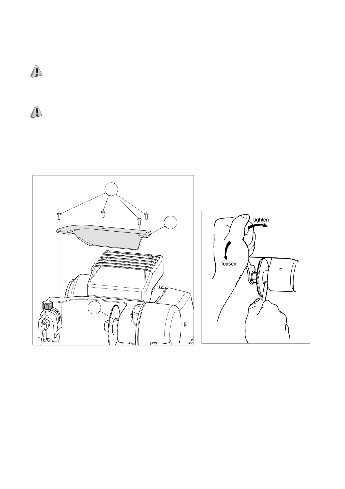
6.5 Access to the lower compartment
ATTENTION: remove the mains plug.
1) Detach the wire from the key-cutting machine socket.
2) Remove the swarf tray (L) (Fig. 39).
3) Paying attention turn the machine slowly onto its back
4) Loosen the 3 screws (W1) and remove the plate (W) (Fig. 40).
.
W
W1
L
Fig. 39 Fig. 40
6.6 Replacing the main switch
ATTENTION: remove the mains plug.
1) Access the lower compartment (see chap. 6.5).
2) Detach the 4 connectors (H2) and (H3) paying special attention to their position (Fig. 41).
3) Remove the switch making pressure on the tabs with a screwdriver (Fig. 42).
4) Fit the new main switch.
5) Reconnect the 4 connectors (H2) and (H3).
Fig. 41 Fig. 42
Copyright Silca 2014
25
Page 30

Operating manual FASTBIT
6.7 Replacing the motor
ATTENTION: remove the mains plug.
1) Access the lower compartment (see chap. 6.5).
2) Disconnect the 2 connectors (H2). Loosen the nut (T1) and
disconnect the earthing wire (Fig. 43).
3) Remove the wire tie.
4) Loosen and remove the 4 motor fi xing nuts (Fig. 44).
5) Re-position the machine on the workbench.
6) Remove the screws (P1), then the protective cover (P) (Fig.
45).
7) Unscrew the wire grommet (M3) (Fig. 46).
8) Remove the 4 motor fi xing screws (M1) and pull off the belt.
9) Loosen the grub screw (S1) and remove the drive pulley (Fig.
47).
10) Pull out the motor cable and remove the motor (Fig. 48).
11) the new motor, the 4 screws (M1) and 4 nuts (M4).
12) Fit the drive pulley onto the new motor and secure with the grub
screw (S1).
13) Fit the belt and adjust tension, tighten the 4 screws (M1) and 4
motor fi xing nuts (M4).
Fig. 43
14) Pass the motor cable through the grommet (M3).
15) Connect the 2 connectors (H2) to the switch (H) and secure the earthing wire to its screw with a nut (T1).
16) Replace and secure the metal bottom (W) (chap. 6.5).
17) Replace the protective cover (P) and secure with the 3 screws (P1).
Fig. 44 Fig. 45
26
Copyright Silca 2014
Page 31

Operating manual FASTBIT
Fig. 46 Fig. 47
Fig. 48
6.8 Replacing and/or adjusting tension on the belt
Worn or loose belts must be replaced or adjusted so as to ensure safe and proper operation of the cutting tool/
brush.
ATTENTION: remove the mains plug.
1) Turn the machine onto its back and loosen the 4
nuts (M4) (chap. 6.7).
2) Re-position the machine on the workbench.
3) Remove the cover (P) by loosening the screws
(P1) (Fig. 45).
4) Move the motor towards the cutter and remove
the worn belt.
5) Fit the new belt.
6) Push the motor to the back until the belt has the
right tension.
7) Tighten the four screws (M1) and the 4 nuts (M4).
8) Place the motor cover (P) and secure with the 3
screws (P1).
Fig. 49
Copyright Silca 2014
27
Page 32

Operating manual FASTBIT
6.9 Replacing the motor on switch
ATTENTION: remove the mains plug.
1) Loosen the 2 screws (M2) and remove the motor cover (Fig. 50).
2) Detach the 4 connectors (K2) paying special attention to their position.
3) Remove the switch (K) making pressure on the tabs with a screwdriver.
4) Fit the new switch in its seat and reconnect the 4 connectors (K2) paying special attention to their position.
5) Re-place the motor cover and secure with the 2 screws (M2).
Fig. 50 Fig. 51
6.10 Replacing the condenser
ATTENTION: remove the mains plug.
1) Loosen the 2 screws (M2) and remove the motor cover (Fig. 50).
2) Detach the connectors (Z) paying special attention to their position.
3) Remove the condenser (Y).
4) Fit the new condenser (Z).
5) Re-place the motor cover and secure with the 2 screws (M2).
28
Fig. 52 Fig. 53
Copyright Silca 2014
Page 33

Operating manual FASTBIT
7 DISPOSING OF MACHINE
EU regulations establish special arrangements for the disposal of waste (**)
Waste deriving from cutting operations
Although residue coming from the key-cutting operations is classifi ed as special waste, it is included in solid
urban waste (SUW) as metal wool. Such waste is sorted according to its classifi cation under current Italian and
EU law and consigned to the proper disposal units.
Cases where waste can be considered contaminated or containing toxic/harmful substances suffi cient to
transform it from SUW to toxic/harmful waste, are listed in the enclosures to current Italian and EU waste disposal
regulations.
Re-cycling is a recommended ecological practice.
Packing
The key-cutting machine is consigned in a cardboard packing box which can be re-used if undamaged.
When it is to be thrown away it is classifi ed as solid urban waste and should be placed in the special paper
collecting bins.
The protective shell containing the machine is in polymer, classifi ed as SUW, and can therefore be placed in an
ordinary waste bin.
INFORMATION FOR USERS
as per art. 10 of Directive 2002/96/CE of 27/01/2003
regarding waste from electric and electronic appliances (RAEE),
• The symbol illustrated above, also found on the machine, indicates that it has been placed on the market
and must be included in separate rubbish collection when the user wishes to dispose of it (including all
components, sub-assemblies and consumables that are integrated in the product).
• For information about the collection system for such appliances please contact SILCA S.p.A. or another
subject registered in the various National Rolls for other countries in the European Union. Household waste(or
of similar origin) can be included in the separate collection system for urban waste.
• On purchasing a new appliance of equivalent type, the old one can be consigned to the dealer. The dealer will
then contact whoever is responsible for collecting the appliance.
• Suitable separate collection of the unused appliance and its dispatch for treatment, recovery and environmentally
compatible disposal, makes it possible to avoid potential negative effects on the environment and human
health, and aids recycling and the recovery of the materials used.
• Unauthorised disposal of the product by users involves the application of the sanctions provided for in received
Directives 91/156/CE and 91/689/CE.
(**) Waste is any substance or object deriving from human activity or natural cycles, disposed off or to be disposed off.
Copyright Silca 2014
29
Page 34

Operating manual FASTBIT
8 ASSISTANCE
Silca provides full assistance to purchasers of the key-cutting machine. T o ensure complete safety for the operator ,
any job not specifi ed in this manual should be carried out by the manufacturer or in the special Service Centres
recommended by Silca.
On the back cover of this manual is a list of the manufacturer’s addresses; listed below are the addresses of
specialised Service Centres.
8.1 How to request service
The guarantee attached to the key-cutting machines ensures free repairs or replacements of faulty parts within
24 months of purchase. All other service calls must be arranged by the customer with Silca or with a Silca service
centre.
30
Copyright Silca 2014
Page 35

VITTORIO VENETO 02/09/2014
CE DECLARATION OF MACHINE COMPLIANCE
SILCA S.p.A. - VIA PODGORA 20 ( Z.I.)
31029 VITTORIO VENETO (TV) - (ITALY)
TEL. 0438 9136 - FAX. 0438 913800
Declares under its own responsibility that the Key-cutting machine model
FASTBIT / FASTBIT II
complies with the requirements of the following European Directives:
European Union DIRECTIVE 2006/42/CE (Machines)
and with the ENISO 12100 : 2010 Standards
European Union DIRECTIVE 2004/108/CE
and with the IEC 61000 – 6 – 3 :2006 , IEC 61000 – 6 – 1 :2005
CISPR14 – 1 : 2009 / EN 55014 – 1 :2009
IEC/EN 61000 – 3 – 2 : 2005 , IEC/EN 61000 - 3 – 3 .2005 Standards
European Union DIRECTIVE 2006/95/CE (Low Voltage) | 14 |
and with the IEC/EN 60204 – 1 : 2009 Standards
Claudio Tomasella of the Silca S.p.A. Research & Development Division is authorized
to create a Technical File.
General Manager Basic Production Center
(Electromagnetic Compatibility)
Page 36

SILCA S.p.A.
Via Podgora, 20 (Z.I.)
31029 VITTORIO VENETO (TV)
Tel. 0438 9136 Fax 0438 913800
E-mail: silca@silca.it
www.silca.biz
Members of the Kaba Group
 Loading...