

Page 1

Operating manual
D424556XA
vers.
3.0
®
Page 2

©
This manual has been drawn up by SILCA S.p.A.
All rights reserved. No part of this publication may be reproduced or used in any form or by any means (photocopying,
microfilm or other) without the written permission of SILCA S.p.A.
Published in june 2002
Printed in Vittorio Veneto
by SILCA S.p.A.
via Podgora, 20 (Z.I.)
31029 VITTORIO VENETO (TV) - Italy
SILCA S.p.A - Vittorio Veneto
2002
Page 3

CONTENTS
GUIDE TO THE MANUAL ......................................................................................1
GENERAL INSTRUCTIONS ..................................................................................2
1 TRANSPORT ...................................................................................................3
1.1 Packing .................................................................................................3
1.2 Transport ..............................................................................................3
1.3 Unpacking .............................................................................................3
1.4 Machine handling ............................................ ... ...................................3
2 WORKING PARTS ..........................................................................................4
3 MACHINE DESCRIPTION ...............................................................................5
3.1 Technical data ............................... .......................................................6
3.2 Electrical circuit .................................
4 ACCESSORIES PROVIDED .................................. ..................................... .. ..8
....................................................7
5 MACHINE INSTALLATION AND PREPARATION .........................................
5.1 Checking for damage ............................................................................
5.2 Environmental conditions ......................................................................9
5.3 Positioning ............................................................................................9
5.4 Description of work station ..................................................................10
5.5 Graphics .............................................................................................10
5.6 Separate parts ............................................. ... ....................................10
5.7 Connection to the mains .....................................................................10
6 REGULATION AND USE OF THE MACHINE ..............................................
6.1 Checking and Setting ..........................................................................11
6.2 Axial gauging ......................................................................................11
6.3 Cutting operations ...............................................................................12
6.4 Key cutting ..........................................................................................12
6.5 Checking set codes (Ford - Jaguar) ...................................................13
6.6 Setting the coded device ....................................................................13
6.7 Coded key-cutting ...............................................................................13
7 MAINTENANCE .............................................................................................
7.1 Cutting tool replacement .....................................................................14
7.2 Brush replacement ..............................................................................14
7.3 Tracer point replacement .................................................................. ..15
7.4 Replacing the fuses ................................................ ... ... ......................15
9
9
11
14
8 WASTE DISPOSAL .......................................................................................16
9 ASSISTANCE ................................................................................................17
9.1 How to request service .......................................................................17
Page 4

Page 5
Operating manual - English DELTA 2000 FO
GUIDE TO THE MANUAL
This manual has been produced to serve as a guide for users of the DELTA 2000 FO key- cutting
machine. Read it carefully; it is essential if you wish to operate your machine safely and efficiently.
C
ONSULTATION
The contents of the manual are divided into sections relating to:
- Transport and handling ......................................................................................... Ch. 1
- Description of machine and safety devices .......................................................... Ch. 2-3-4-5
- Proper use of the machine ................................................................................... Ch. 5-6
- Maintenance ......................................................................................................... Ch. 7
T
ECHNICAL TERMS
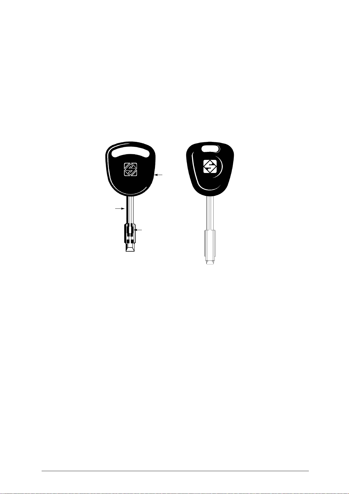
Common technical terms are used in this manual. To assist those with little experience of key cutting,
below is an illustration of the terms used for the different parts of keys.
1
Fig. 1
2
4
3
1) Head
2) Stem
3) Tip
4) Cuts
Copyright Silca 1998 1
Page 6
DELTA 2000 FO Operating manual - English
GENERAL INSTRUCTIONS
The DELTA 2000 FO key-cutting machine has been designed according to the specifications of the
Machine Directives. From the design stage risks for the operator have been eliminated in all areas:
transport, regulation, cutting and maintenan ce .
The use of protective goggles is compulso ry during cutting operations, as indicated o n the machine itself
and in this manual.
The material used in the manufacture of this machine and the components employed during use of the
machine are not dangerous and their use complies with standards.
U
SE
The DELTA 2000 FO key-cutting machine must be installed and used in the way laid down by the
manufacturer, as illustrated in this manual.
If the machine is used differently or for purposes different from those descri bed in this manual, the
customer will forego any rights he may ha ve over SIL CA S.p.A . Furthermor e, unfore seen dang er to the
operator or any third parties may arise from incorrect use of the machine.
Negligence in the use of the machine or failure on the part of the operator to observe the instructions
given in this manual are not covered by the guarantee and the manufacturer declines all responsibility
in such cases.
It is therefore indispensable to read the operating manual carefully in order to make th e best use
of the DELTA 2000 FO key-cutting machine and benefit from its potential.
F
URTHER RISKS
There are no further risks arising from the use of the DELTA 2000 FO key-cutting machine.
P
ROTECTION AND SAFETY PRECAUTIONS FOR THE OPERATOR
The DELTA 2000 FO key-cutting machine is built entirely to stan dard s. The ope rati on s for which it has
been designed are easily carried out at no risk to the operator.
The adoption of general safety precautions (use of protective goggles) and observation of the
instructions provided by the manufacturer in this manual eliminate all human error, unless deliberate.
The DELTA 2000 FO key-cutting machine is designed with features which make it completely safe in
all its parts.
• Power supply
The key-cutting machine must be supplied with electricity by means of a safety device (supplied with
the 230V machines; on request for other voltages). The plug must be earthed.
• Start-up
The machine is started up by means of:
1) the safety device switch (supplied with the 230V machines);
2) the ON switch, situated on the machine, which activates the machine motor.
• Maintenance
The operations to regulate, service, repair and clean the machine have been devised in the simplest
and safest way possible. There is no danger of removable parts being replaced wrongly or unsafely.
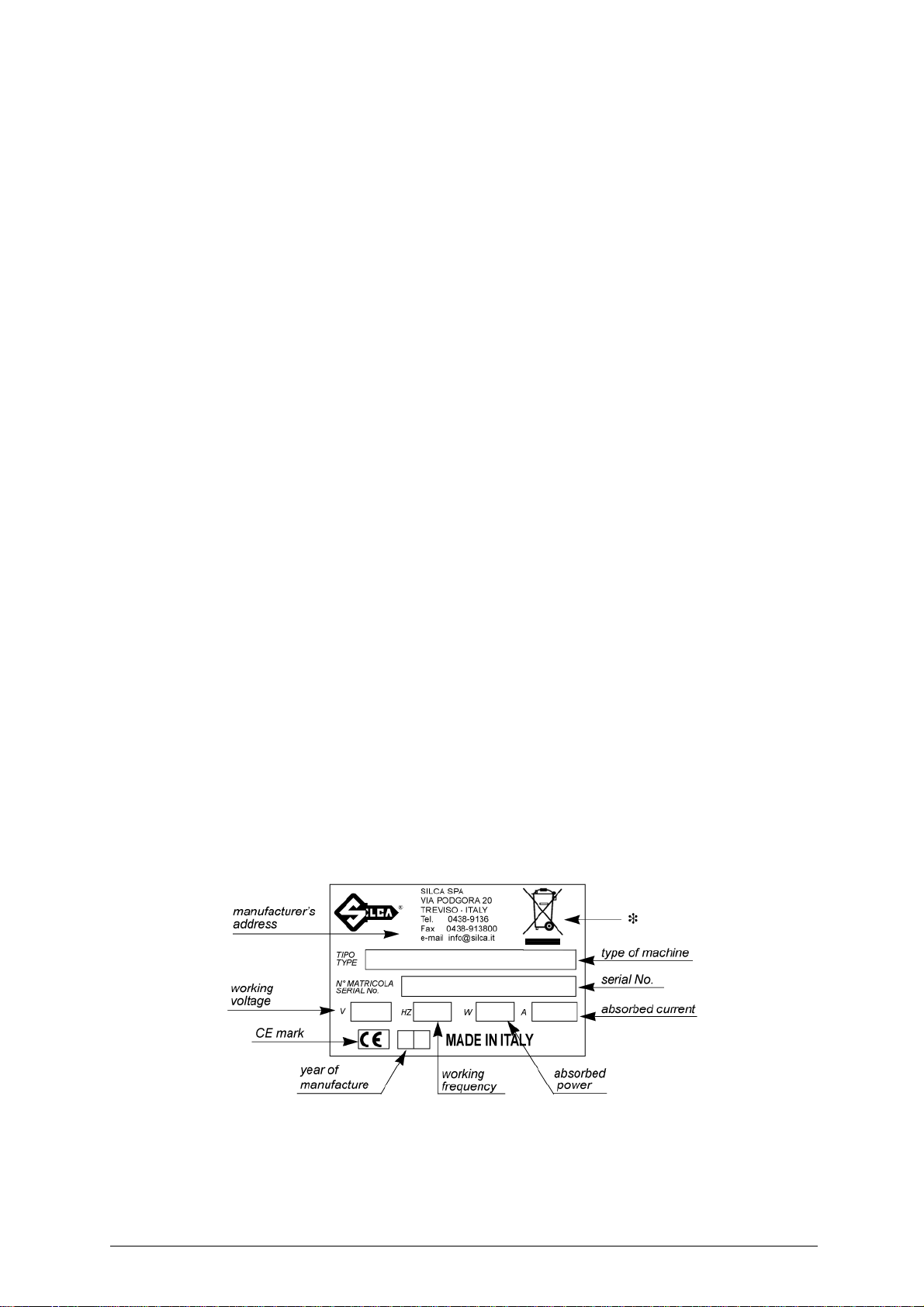
• Machine identification
The DELTA 2000 FO is provided with an identification label which shows the serial number (fig.2).
ATTENTION: should the machine be left on continuously for over 50 minutes, the cutting tool motor is protected
against overheating and will automatically cut out. In such cases, proceed as follows:
a) turn off the master switch (D) (fig.5, page 4);
b) let the motor cool for at least 2 hours before using the machine again.
Fig. 2
(*) seechap.8 WASTE DISPOSAL, page 16.
2 Copyright Silca 1998
Page 7
Operating manual - English DELTA 2000 FO
1 TRANSPORT
The DELTA 2000 FO key-cutting machine is easily transported and is not dangerous to handle.
The packed machine can be carried by one person.
1.1 Packing
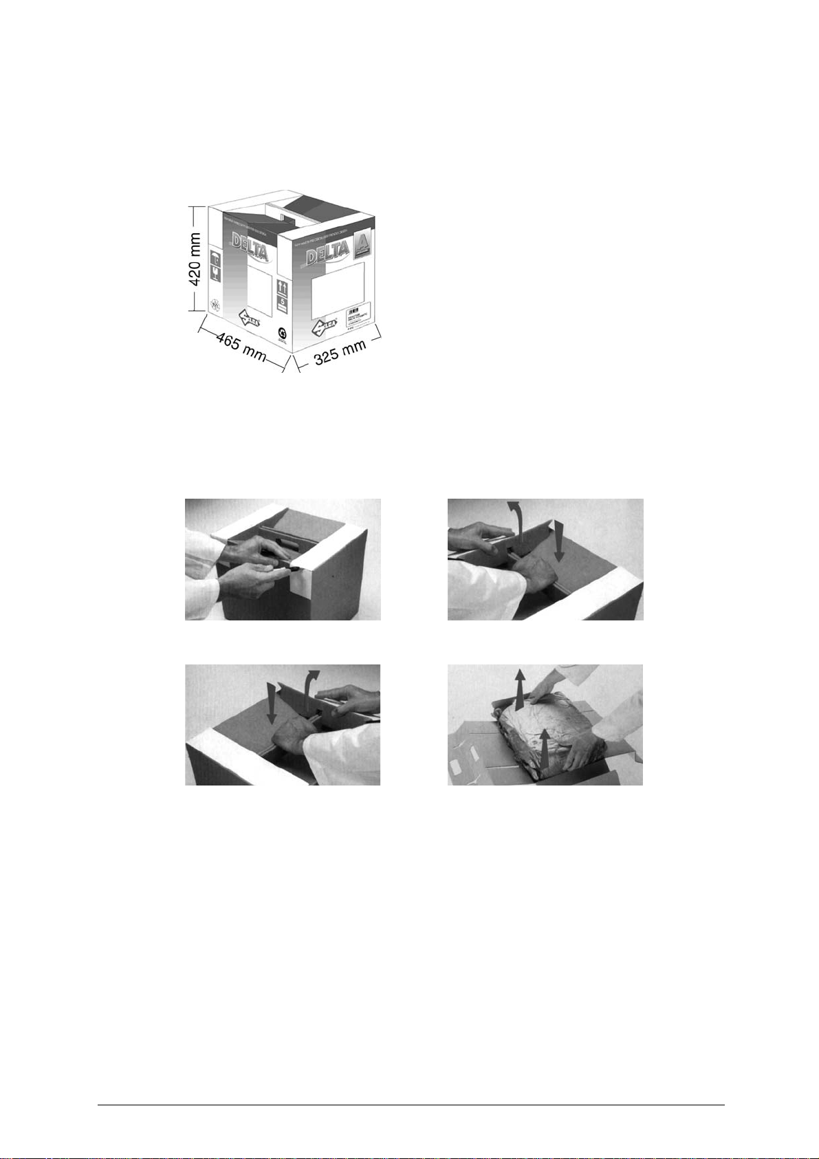
The DELTA 2000 FO key-cutting mach ine comes in a strong
cardboard box, the dime nsions of wh ich are sh own in fig.5,
designed to protect the machine and all its parts even when
it is stored for long periods.
Fig. 3
1.2 Transport
It is advisable to use the packing every time the machine is transported, as this will avoid knocks which
could cause damage to the machine, persons or things.
1.3 Unpacking
To remove the machine from the packing box, carefully follow the illustrated instructions below:
Fig. 4
Check the contents of the box, which should comprise:
1 DELTA 2000 FO key-cutting machine;
1set of documents including: operating manual, spare parts list and guarantee;
1chippings tray;
1 power cable;
1 power supply safety device (supp
1 set of accessories.
AB
CD
lied with the 230V machines);
1.4 Machine handling
When the DELTA 2000 FO key-cutting machine has been unpacke d, place it directl y on its workben ch.
This operation can be carried out by one person,
and carry the machine
firmly holding the base, and no other part, to lift
.
Copyright Silca 1998 3
Page 8
DELTA 2000 FO Operating manual - English
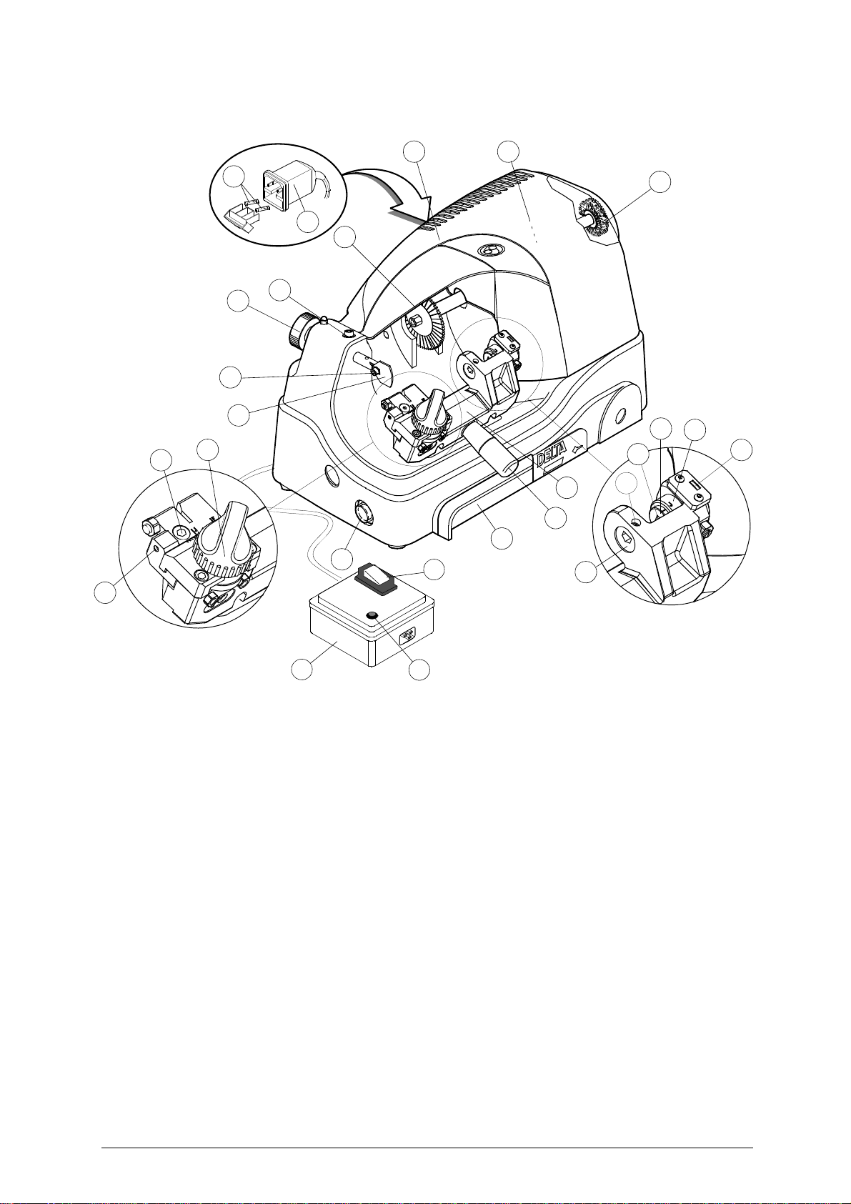
2 WORKING PARTS
H
L
I
J
K
G
F3
F2
F1
F
A3
A4
E1
E2
A2
B
A1
A5
B1
C
D
X1
A
E
Fig. 5
CODED SPACING
DEVICE
A - rotating centring clamp
A1 - key-locking grub screw
A2 - tip stop groove
A3 - Ford/Jaguar selection cylinder
A4 - coded angle device drum
A5 - angle code viewing window
B - carriage
B1 - carriage lever handle
C - chippings tray
D - motor/brush start button
E - axis regulation grub screw
E1 - axis regulation locking screw
E2 - coded spacing device knob
F - tracer point
F1 - tracer point locking screw
F2 - adjusting nut
F3 - tracer point’s group locking screw
G - cutting tool
H - carter
I-motor
J - brush
K - supply socket
L - fuses
X
CODED ANGLE
DEVICE
X2
X - safety device (supplied with the 230V machines; on request for other voltages)
X1 - safety device main switch
X2 - warning light
4 Copyright Silca 1998
Page 9
Operating manual - English DELTA 2000 FO
3 MACHINE DESCRIPTION
DELTA 2000 FO is a professional key-cutting machine for FORD® and JAGUAR® car keys. The
machine comprises the following main parts:
S
AFETY DEVICE
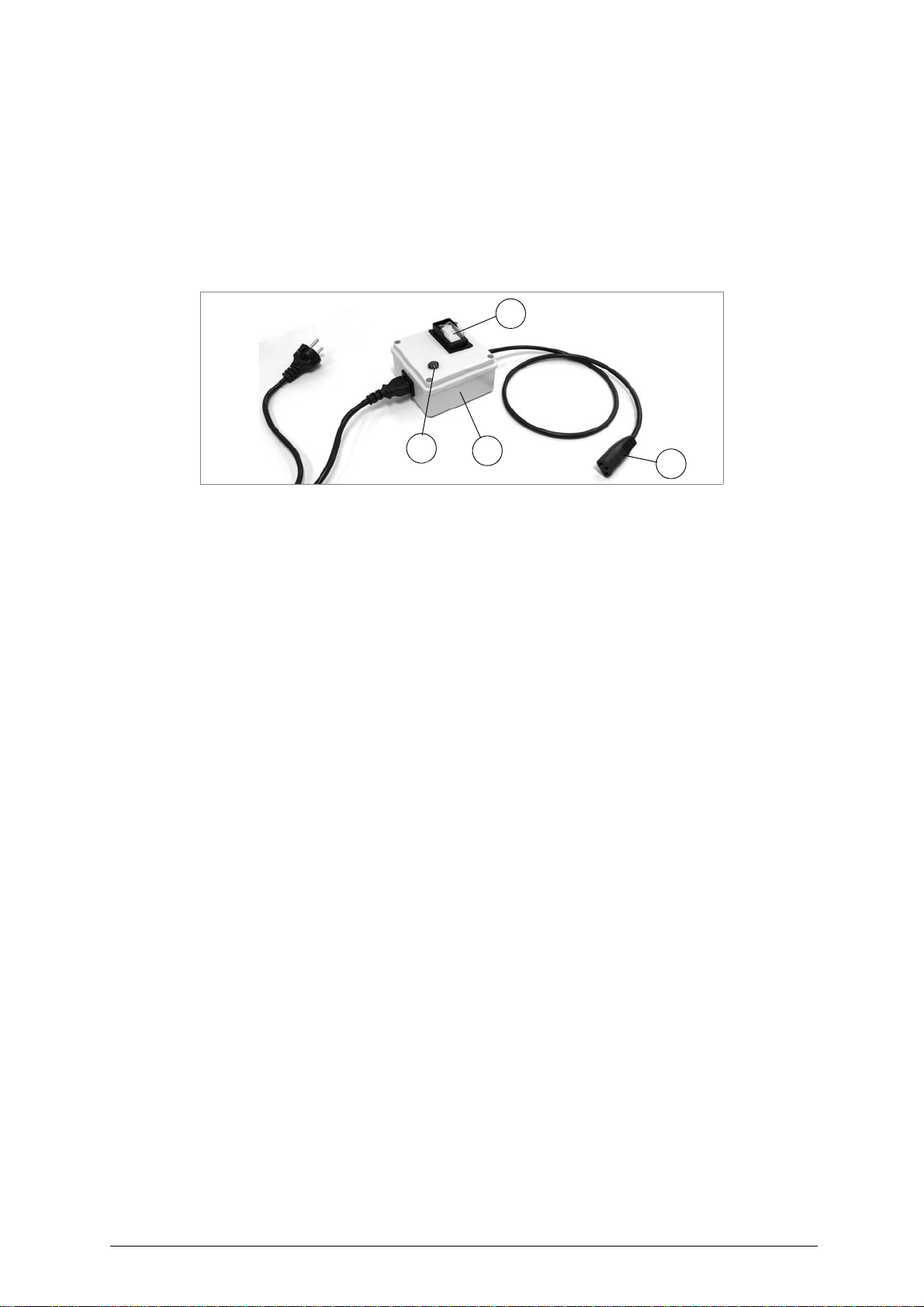
The device is connected to a power plug with a differential switch. power the key-cutting machine
by pressing the switch (X1)
The warning light (X2) illuminates to indicate voltage in the plug (X3).
WARNING: Switch (X1) is electromagnetic, in the event of a power failure it goes out automatically. When
electricity is restored it must be reset manually to power the machine again by means of the plug
(X3).
(fig. 6)
.
X1
X2
Fig. 6
M
ASTER SWITCH (D
The motor and brush starting button (D) is placed on the left side of the DELTA 2000 FO key-cutting
machine.
ATTENTION: the switch is constantly illuminated to indicate that the machine is live.
M
OTOR
The DELTA 2000 FO has a direct drive motor. The transmission unit comprises the motor, cutter and
brush and is protected by a single cover (H).
M
OBILE UNIT
The mobile unit comprises a carriage (B) to which is fitted the coded spacing device and a key-locking
clamp with a coded angle device.
The carriage is fitted to the translation shaft and is moved manually by the operator.
It has been designed to avoid the accumulation of cutting dust or chippings.
The key-cutting machine has an inclined table which allows the chippings to collect in the special tray
(C) pl
aced under the carriage and easily removable for thorough cleaning.
•Brush (J)
The brush is used to eliminate burrs caused by the cutting process and is made of safe materials.
• Cutting tool (G)
The cutting tool is the part of the DELTA 2000 FO machine which cuts the ke y blank. The tool is in HSS
super rapid steel and is protected by a special cover (H) to ensure safe operation.
• Tracer point (F)
The tracer point is hous ed on the left-hand side of the machine base. Its depth settings are easily
regulated with the ring nut (F2).
• Coded angle device
The device comprises:
- tip stop (A2) connected directly to the angle setting device;
- idle bush (A) for centring and locking the key.
• Key-locking grub screw (A1)
The key is secured by means of a grub screw which ensures perfect grip on the key.
• Coded spacing device
The code device comprises a knob (E2) to activate a graduated slide which determines the position of
the various cuts.
)
X
X3
Copyright Silca 1998 5
Page 10

DELTA 2000 FO Operating manual - English
3.1 Technical data
ELECTRICAL PROPERTIES: 230V - 50Hz 190W 1,5A
110V - 60Hz 250W 3,5A
CUTTING TOOL: Super Rapid Steel (HSS)
MOTOR: One speed single phase
SAFETY DEVICE: supplied with 230V key-cutting machines
CLAMP: rocker
CARRIAGE MOVEMENT: manual
CARRIAGE RUN (maximum length of cuts): 23
DIMENSIONS: width: 210 mm depth: 370 mm height: 250 mm
CUTTING NOISE: Lp (A)= 92,2 dB (A)
NOISE POTENTIAL: Lw (A)= 104,9 dB (A)
WEIGHT: Kg. 14
230V-50Hz 1350 rpm 0,145 Kw
110V - 60Hz 1700 rpm 0,180 Kw
mm
6 Copyright Silca 1998
Page 11
Operating manual - English DELTA 2000 FO
3.2 Electrical circuit
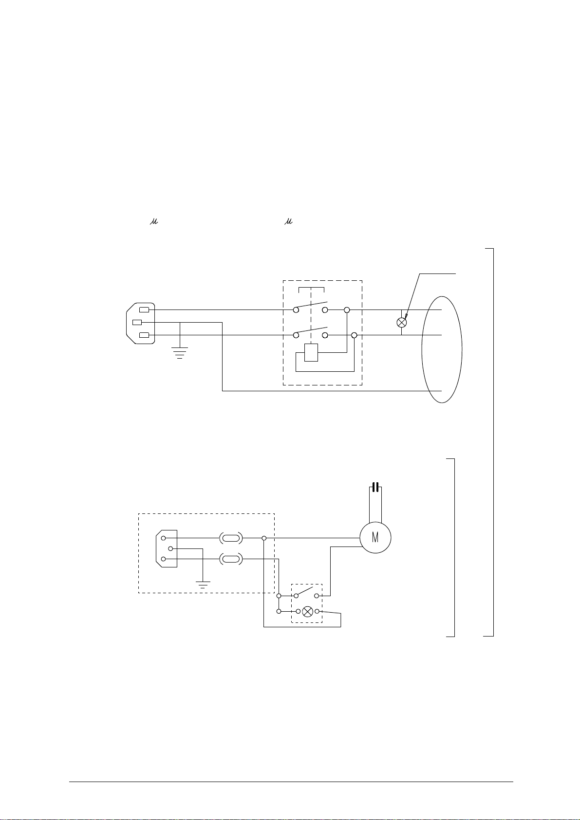
The DELTA 2000 FO key-cutting machine is provided with a motor which performs:
- 1350 rpm with consumption of approx. 0,19 kw and absorption of 1,5A on 230V version;
- 1700 rpm with consumption of approx 0,25Kw and absorption of 3,5A on 110V version.
The main parts of the electrical circuit are listed below:
1) Safety device inlet
2) Safety main switch
3) Warning light
4) Wiring clip
5) Machine inlet
6) Rapid 3,15A fuses (230V); 6,3A (110V)
7) Switch with lamp
8) Motor: 230V a.c. 50Hz
9) 6,3 F condenser on 230V version; 20 F on 110V version
Safety device
2
brown
1
yellow-green
light blue
brown
light blue
3
4
IN
OUT
230V
9
machine inlet
6
8
5
6
motor
110V
7
Copyright Silca 1998 7
Page 12
DELTA 2000 FO Operating manual - English
4 ACCESSORIES PROVIDED
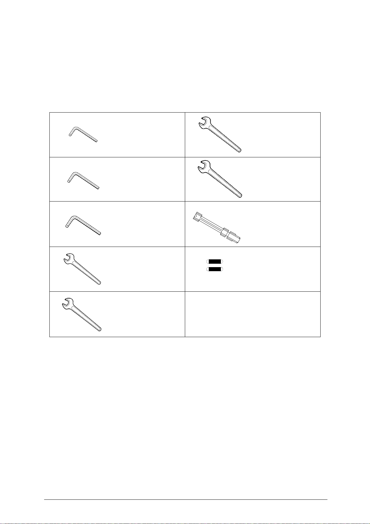
To ensure trouble-free wor king with t he DELTA 2000 FO, it is advisabl e to always h ave certain s pare
parts on hand.
It is advisable to always have a tool box co ntaining : tools, cu tting too ls, brushes an d small re placement
parts.
DELTA 2000 FO is supplied with a full range of accessories.
The accessories provided by Silca are all that is ne
machine is designed.
cessary to carry out the operations for which the
1
2
3
4
5
code
D300222ZZ
2,5 mm Allen key
code
D300223ZZ
3 mm Allen key
code
D300224ZZ
4 mm Allen key
code
D302883ZZ
8 mm Spanner
code
D300308ZZ
6
7
8
9
code
D312327ZZ
15 mm Spanner
code
D301760ZZ
17 mm Spanner
code
D413665LA
gauging calliper
cod
e
D309226ZZ
Fuses 5X20 3,15A rapid (230V)
cod
e
D306748ZZ
Fuses 5X20 6,3A rapid (110V)
10 mm Spanner
8 Copyright Silca 1998
Page 13
Operating manual - English DELTA 2000 FO
5 MACHINE INSTALLATION AND PREPARATION
The DELTA 2000 FO key-cutting machine can be installed by the purchaser and does not require any
special skills. However, some checks and preparation for use need to be carried out by the operator.
5.1 Checking for damage
The DELTA 2000 FO is solid and compact and will not normally damage if transport, unpacking and
installation have all been carried out according to the instructions on the packing box.
However, it is always advisable to check that the machine has not suffered any damage.
5.2 Environmental conditions
To ensure that the best use is made of the key-cutting machine, certain parameters must be borne in
mind:
- damp, badly ventilated sites should be avoided.
- the conditions for the machine are:
temperature:between 0 and 40°C relative humidity:approx. 60%
5.3 Positioning
Place the machine on a horizontal surface, solid enough to take the weight (14 Kg).
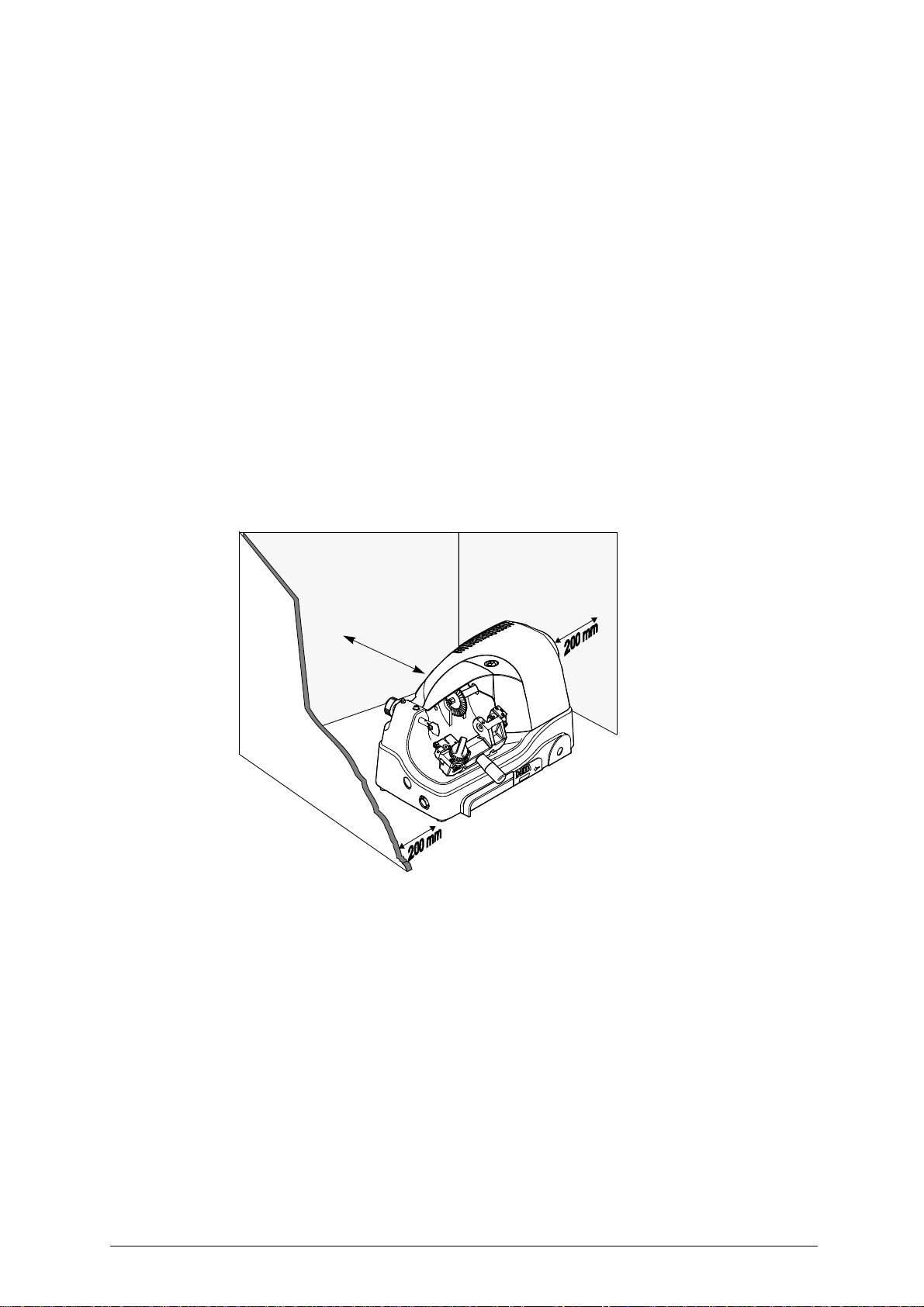
To facilitate operation and maintenance, install the machine with a clearance of at least 200 mm on all
si
des (fig.7).
Check that the weight of the machine is evenly distributed over the four feet; horizontal positioning
revents vibrations during operation.
p
ATTENTION: ensure that the machine voltage is the same as that of the mains, which must be properly earthed and
provided with a differential switch.
Fig. 7
20
0
m
m
Copyright Silca 1998 9
Page 14
DELTA 2000 FO Operating manual - English
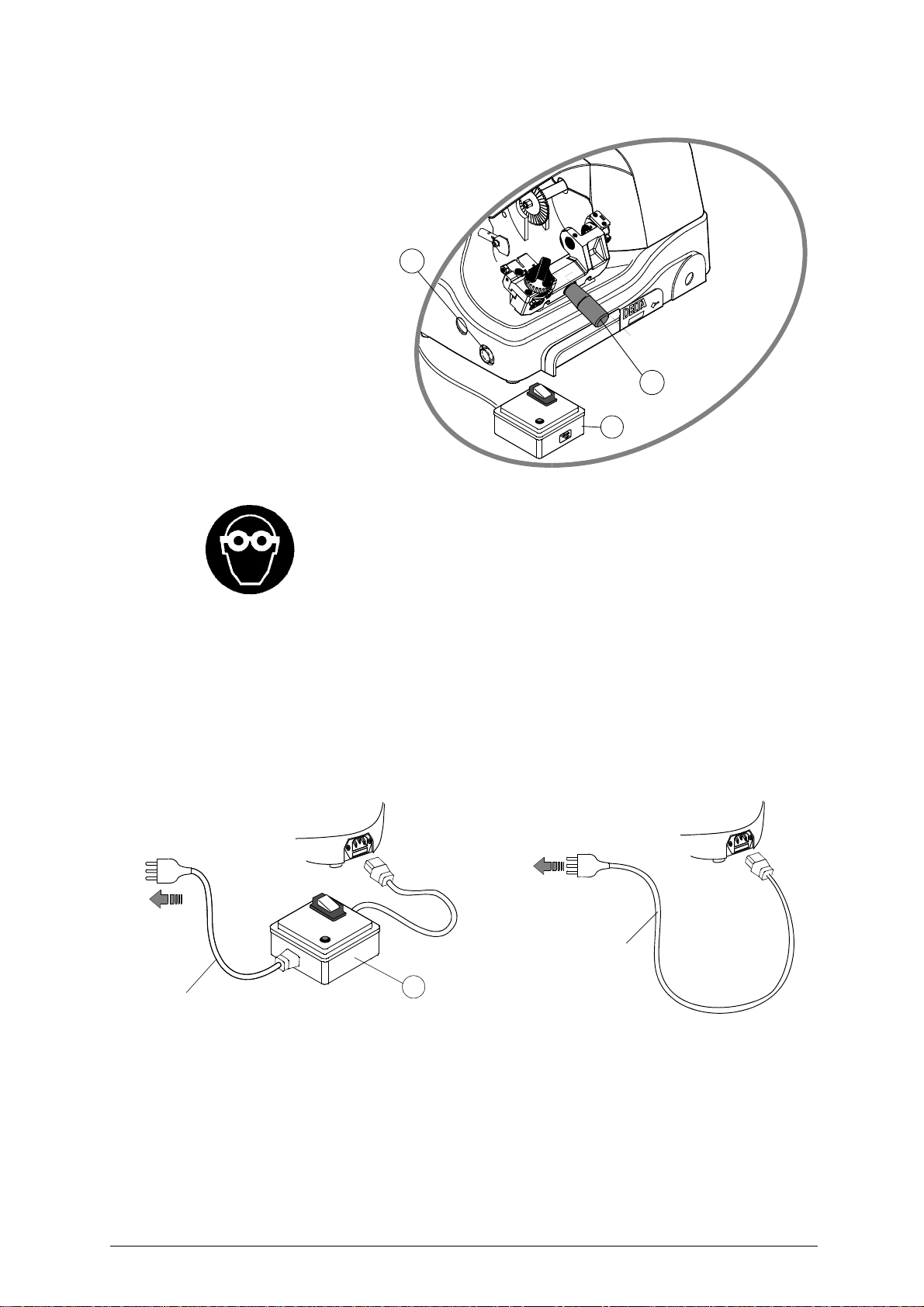
5.4 Description of work station
The machine needs only one
operator, who has the following
ntrols at his/her disposal
co
(fig.8):
- safety device (X).
- master switch (D), placed
on
the left-hand side of the
machine; provided with a
warning light indicating that
the machine is live.
- carriage lever handle (B1).
Fig. 8
D
B1
X
5.5
Graphics
5.6 Separate parts
The detachable parts of the machine are packed separately and must be fitted to the DELTA 2000 FO
by the operator, as follows:
P
OWER CABLE
230V version:
first connect the safety device (X) to the key-cut ting machine a nd the power cable then conne ct the free
end of the power cable to the power mains (fig.9).
110V version:
connect the key-cutting machine and the power cable then connect the free end of the power cable to
the power mains (
power
mains
fig.9).
THE USE OF PROTECTIVE GOGGLES IS
COMPULSORY
power
mains
power cable
Fig. 9
X
5.7 Connection to the mains
It is extremely import ant for th e operat or’s safety to ensur e that the key-cutting machine i s connected
to the power mains with the right voltage and by means of a properly earthed differential switch.
10 Copyright Silca 1998
power cable
Page 15
Operating manual - English DELTA 2000 FO
6 REGULATION AND USE OF THE MACHINE
6.1 Checking and Setting
The cutting tool on the DELTA 2000 FO is u sed to cut the key blanks an d must be periodica lly checked
and replaced.
Periodically, and whenever the cutting tool is replaced, check the key-cutting machine settings, to
ensure perfect machine efficiency.
6.2 Axial gauging
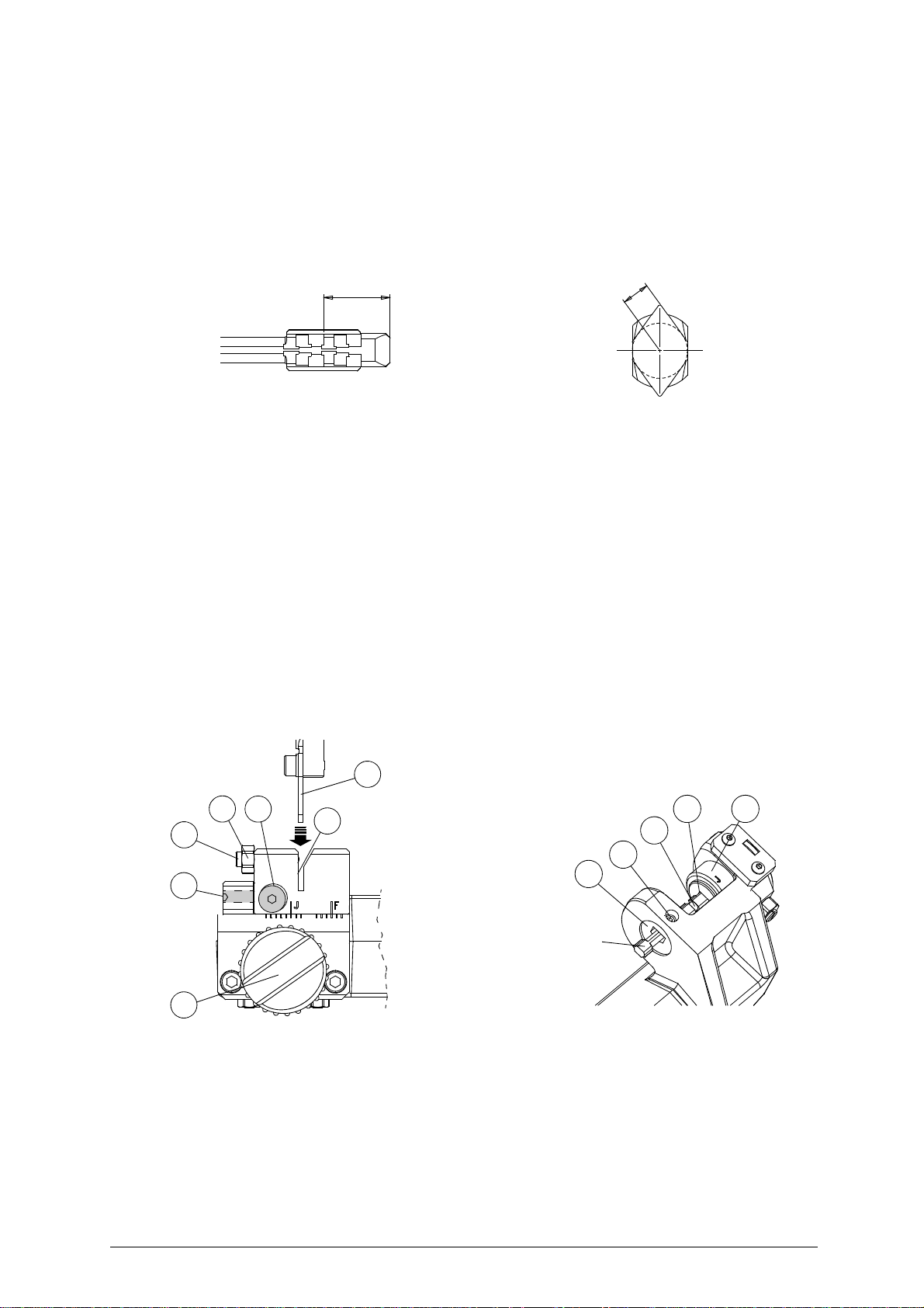
Axial gauging is regulation of the position of the cutting spaces (fig.10).
Fig. 10
A
XIAL GAUGING REGULATION
To regulate the axial gauging, proceed as follows:
ATTENTION: disconnect the machine from the mains.
1) set up the coded spacing device by means of the knob (E2) so that the indicator "F" is aligned with
position "d" (fig.12).
2) insert the tip of the gauging calliper (provided) into the rotating clamp (A), push up against the tip
stop
(A2) and lock in the calliper by tightening the grub screw (A1) (fig.13). The calliper must be
positioned horizontally as shown in the illustration; if adjustment is necessary use the hex wrench
pro
vided to turn the screw (P) (fig.17, page 13) so that the drum (A4) turns clockwise.
3) take the carriage towards the cutting tool and place the tracer point (F) all the way into the locating
ove (E3) (fig.12).
gro
4) check that the cutting tool enters clearly int o the groove (A3) in the gau ging calliper. If a djustment is
ne
cessary, loosen screw (E1) and adjust axial gauging by means of the grub screw (E).
5) when gauging is complete, tighten the screw (E1) well.
D
EPTH SETTING
Depth setting is regulation of the cutting depth (fig.11). Usually depth setting is not necessary during
normal use of the machine. However, if the tracer point is replaced or an optional carriage is used it is
ad
visable to check the depth settings.
Fig. 11
F
O
E1
E3
N
E
A2
A4
A3
A1
A
Fig. 12
E2
d
Copyright Silca 1998 11
gauging
calliper
Fig. 13
Page 16
DELTA 2000 FO Operating manual - English
R
EGULATING DEPTH SETTING
To regulate the depth settings, proceed as follows:
ATTENTION: disconnect the machine from the mains.
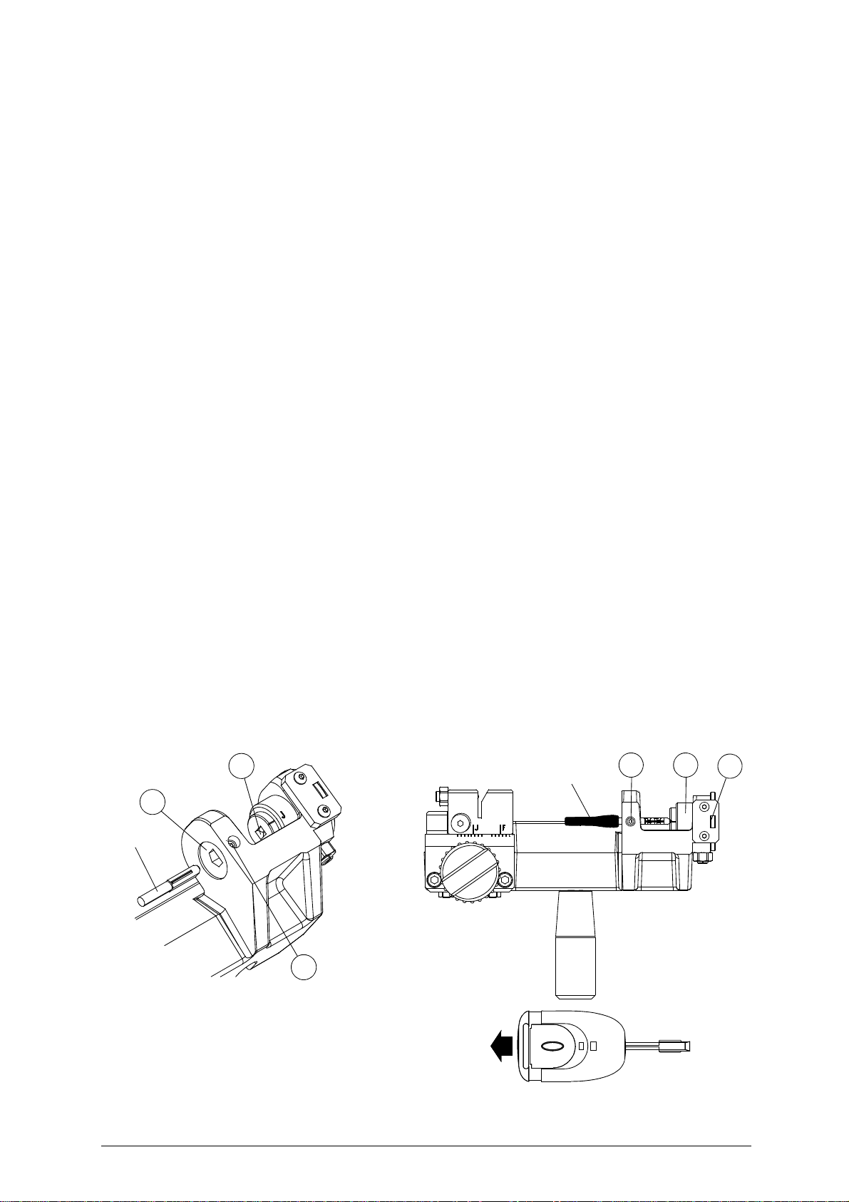
1) set up the coded spacing device by means of the knob (E2) so that the indicator "F" is aligned with
position "d" (fig.12).
2) insert the tip of the gauging calliper (provided) into the rotating clamp (A), push up against the tip
3) take the carriage towards the cutting tool and place the tracer point (F) all the way into the locating
4) check that the cutting tool enters clearly int o the groove (A3) in the gau ging calliper. If a djustment is
5) loosen the screw (F3) locking the tracer point unit ( fig.5, page 4).
6) use the lateral brush (J) to turn the cutting tool shaft in the oppo si te dire cti on to cu tti ng. The cutti ng
7) when the ideal regulation has be en rea ched , ti gh ten th e t racer poi nt lo ckin g screw ( F3) ( fi g.5 , p age
If an optional carriage is used, check that the tracer po
(fig.12, page 11) and that there is no t excessive play on it. If ne
groove and tracer point by loosening the nut (O) and turning the grub screw (N).
When adjustment is complete, tighten the nut (O).
(A2) and lock in the calliper by tightening the grub screw (A1) (fig.13). The calliper must be
stop
positioned horizontally as shown in the illustration; if adjustment is necessary use the hex wrench
provided to turn the screw (P) (fig.17, page 13) so that the drum (A4) turns clockwise.
gro
ove (E3) (fig.12, page 11).
ne
cessary, adjust axial gauging in the way described above ("Axial gauging regulation").
t
ool should skim the bottom of th e groo ve (A 3) on th e gau ging call iper . If not, t urn the rin g nut (F2)
(fig.5, page 4) clockwise to move the cutting tool unit forward, or in th e opp osite d irect ion t o mo ve i t
back.
4).
int enters freely into the locating groove (E3)
cessary, adjust play between the locating
6.3 Cutting operations
ATTENTION: to work in complete safety, pay special attention to the following recommendations:
• Always work with dry hands.
• Check that the machine is properly earthed.
• Use the protective goggles, even if the cutting tool is fitted with a protective shield.
• Start the motor only when all the operations with the carriage have been carried out
(se
curing keys, etc.).
• Keep hands away from the cutting tool when in motio n .
6.4 Key cutting
P
LACING KEYS INTO CLAMP
1) place the key blank into the rotating centering clamp (A) (fig.14).
2) push the key tip up against the tip stop groove (A2). Hold down the key and lock into the rotating
ATTENTION: when cutting original FORD keys with lights, before locking into the clamp detach the part containing
the electrical devices, otherwise the head is too big (fig.15).
A
blank-key
p with the grub screw (A1).
clam
A2
blank-key
A1 A4
F
A5
A1
Fig. 14
Fig. 15
12 Copyright Silca 1998
Page 17
Operating manual - English DELTA 2000 FO
6.5 Checking set codes (Ford - Jaguar)
The machine can cut both Ford and Jaguar keys following a sim ple operati on to carry out on the coded
angle device. To check the current setting, proceed as follows:
1) place the key blank tip into the rotating clamp (A) and push up against the tip stop groove (A2).
2) continue to push, and check that the key is in the vertical position (fig.15) and the number "1" is
visible in the window. If necessary, turn the key until it is properly positioned.
3) check the reading on the drum (A4). If the letter "F" is visible the devi ce is set for cutti ng Ford keys,
f the letter "J" is visible the device is set for cutting Jaguar keys.The machine leaves our workshops
i
set for cutting Ford keys.
6.6 Setting the coded device
The change the coded device setting from FORD to JAGUAR and vice versa, proceed as follows:
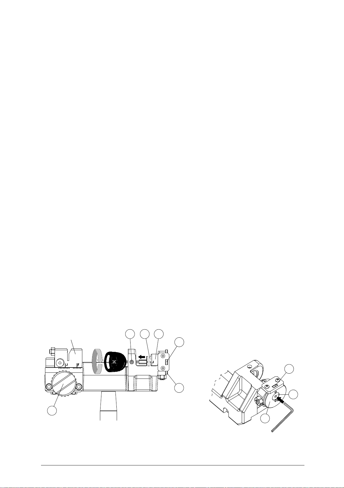
1) place the key blank tip into the rotating clamp (A) and push up against the tip stop groove (A2)
(fig.14, page 12).
2) hold the key head firmly and use the left hand to loosen the screw (P) (fig.17) with the wrench
provided.
3) exert slight pressure in the direction of the arrow (fig.17) and unscrew the screw (P) slowly so that
the cylinder (A3) protrudes a few millimetres (fig.16).
4) use the key head to turn the cylinder 90° in the direction of the arrow.
5) let the cylinder (A3) withdraw and press on the key head to tighten screw (P). The cylinder must
ret
urn freely into its seat. If necessary, seek its proper position by turning the key slightly in the two
directions.
6) turn the key 90° to pull the coded angle device. The letter visible on the drum (A4) will now be
different, as will the colour of the numbers in the window (A5).
6.7 Coded key-cutting
To cut a key blank by code, see the instructions below:
1) check that the coded device has been properly set for the type of key to be cut (see points 6.5 and
6.6).
2) place the key blank into the rot ating clamp (A) and push again st the tip stop groove (A2) (fig.14, page
12). Hold the key down in the rotating clamp (A) and tighten the grub screw (A1) with the wrench
provided.
3) set the cutting position on the coded spaci ng de vice by m
on the head to turn the key and turn the angle counter (Q) (fig.17) until the required code is visible
in the window (A5).
4) start the machine with the motor/brush start switch (D).
5) take the carriage towards the cutting tool, ensuring that the tracer point enters the locating groove
all the way (fig.16). When the cut has been made, move the carriage back and turn the key until the
same code appears in the window (A5), after the number "1" has appeared. Repeat the cutting
eration.
op
6) when the cut has been made, move the carriage back and give the key a half turn until the same
code
appears in the window (A5). Repeat the operation described in point 5.
7) the key has now been cut on both sides for the first cutting position. Go on to the following position
an
d repeat the cutting operations with the relevant code, and so on until all the cuts have been
made.
8) pull back the carriage, turn off the machine, loosen the grub screw (A1) and remove the key.
locating groove
A1
A3
eans of knob (E2) (fig.16). Exert pressure
A4
A5
E2
Fig. 16
A5
Q
P
Q
Fig. 17
Copyright Silca 1998 13
Page 18
DELTA 2000 FO Operating manual - English
7 MAINTENANCE
ATTENTION: for repairs or replacement of parts for maintenance, the ‘CE’ mark is guaranteed only if original spare
ATTENTION: DO NOT USE COMPRESSED AIR!
ATTENTION: to keep the machine well maintained we recom
parts provided by the manufacturer are used.
Although the DELTA 2000 FO key-cutting machine does not require special maintenance, it is advisable
to check and, if necessary, replace the parts subject to wear (cutting tool, brush, tracer point).
Replacement is simple and can be carried out by the operator.
CLEANING
cutting operations.
to the burnished mechanical parts. This prevents oxidation of the parts in question (clamps, guides,
carriages, etc.).
Before starting any type of maintenance (checks or replacements), read the instructions below:
• never carry out maintenance or servicing with the machine switched on.
• always remove the m ains plug.
• follow all the instructions in the manual to the letter.
• use original spare parts.
• always check that any screws or nuts removed when replacing a piece are properly
tig
: it is advisable to use a soft brush to keep the carriage and clamps free of chippings from
mend using protective oil, e.g. WD40 or similar, applied
htened.
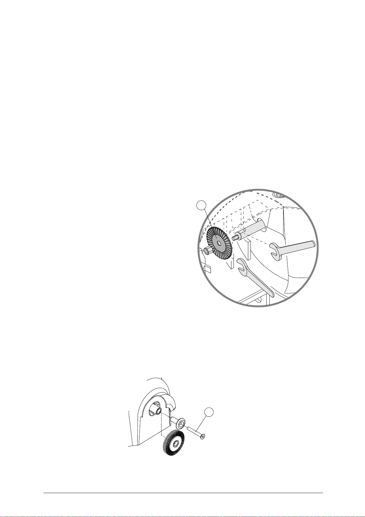
7.1 Cutting tool replacement
It is not necessary to remove the protective
shield in order to replace the cutting tool (G).
ATTENTION: unplug the machine from the mains.
1) place the spanner provided in position on
the motor shaft (fig.18);
2) use a suitable spanner to loosen the new
ATTENTION: the thread is left-handed.
3) replace the cuttin g tool after cleaning its
4) install the new cutting tool and tighten the
ATTENTION: the tool rotates clockwise.
ng tool locking nut.
cutti
seat;
t.
nu
G
7.2 Brush replacement
When the brush (J) is no longer effective it must be replaced, as follows:
ATTENTION: unplug the machine from the mains.
1) place the spanner provided in position on the motor shaft (fig.18);
2) use the wrench provided to loosen the brush locking screw (X) (fig.19);
3) replace the brush and secure with the screw;
4) remove the spanner from the motor shaft.
Fig. 19
Fig. 18
X
14 Copyright Silca 1998
Page 19
Operating manual - English DELTA 2000 FO
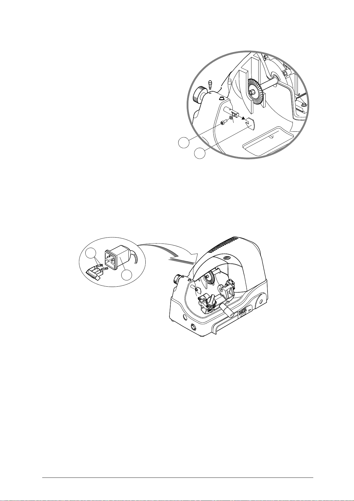
7.3 Tracer point replacement
To replace the tracer point (F), proce ed as
follows (fig.20):
ATTENTION: unplug the machine from the mains.
1) loosen and remove the tracer point
locking screw (F1).
2) remove the tracer point.
3) fit the new tracer point.
4) re-gauge the machine as described in
chapter 6 on page 11.
Fig. 20
F1
F
7.4 Replacing the fuses
ATTENTION: unplug the machine from the mains.
1) detach the wiring from the machine plug;
2) turn the key-cutting machine so that the fuse box is easily reached;
3) remove the fuse box placed below the power inlet (K) (fig.21);
4) replace the fuses (L);
5) close the fuse box and connect the power cable.
ATTENTION: the fuses must both be of the same type (rapid) and with the same amps (3,15 Ampere on 230V, 6,3
Ampere on 110V).
L
K
Fig. 21
Copyright Silca 1998 15
Page 20

DELTA 2000 FO Operating manual - English
8 WASTE DISPOSAL
EU regulations establish special arrangements for the disposal of waste (**).
• Waste deriving from cutting operations
Although residue coming from the key-cutting operations is classified as special waste, it is included in
solid urban waste (SUW) as metal wool.
Such waste is sorted according to its classification under current Italian and EU law and consigned to
the proper disposal units.
Cases where waste can be considered cont aminated or containi ng toxic/harmful substance sufficient to
transform it from SUW to toxic/har mful waste, are listed in the enclosur es to current Italian and EU waste
disposal regulations.
Re-cycling is a recommended ecological practice.
• Packing
The DELTA 2000 FO is consigned in a cardboard packing box which can be re-used if undamaged.
When it is to be thrown away it is classified as solid urban waste and should be placed in the special
paper collecting bins.
INFORMATION FOR USERS
as per art. 10 of Directive 2002/96/CE of 27/01/2003
regarding waste from electric and electronic appliances (RAEE)
• The symbol illustrated above, also found on the machine, indicates that it has been placed on the market
and must be included in separate rubbish collection when the user wishes to dispose of it (including all
components, sub-assemblies and consumables that are integrated in the product).
• For information about the collection system for such appliances please contact SILCA S.p.A. or another
subject registered in the various National Rolls for other countries in the European Union. Household
waste (or of similar origin) can be included in the separate collection system for urban waste.
• On purchasing a new appliance of equivalent type, the old one can be consigned to the dealer. The
dealer will then contact whoever is responsible for collecting the appliance.
• Suitable separate collection of the unused appliance and its dispatch for treatment, recovery and
environmentally compatible disposal, makes it possible to avoid potential negative effects on the
environment and human health, and aids recycling and the recovery of the materials used.
• Unauthorised disposal of the product by users involves the application of the sanctions provided for in
received Directives 91/156/CE and 91/689/CE.
,
(**) "Waste" is any substance or object deriving from human activity or natural cycles, thrown away or
to be thrown away.
16 Copyright Silca 1998
Page 21

Operating manual - English DELTA 2000 FO
9 ASSISTANCE
Silca provides full assistance to purchasers of the DELTA 2000 FO key-cutting machine.
To ensure complete safety for the operator, any job not specified in this manual should be carried out
the manufacturer or in the special Service Centres recommended by Silca.
by
On the back cover of this manual is a list of the manufacturer’s addresses; listed below are the
a
ddresses of specialised Service Centres.
9.1 How to request service
The guarantee attached to DELTA 200 0 FO key-cutt in g ma ch ine e nsure s fre e repairs or replacements
of faulty parts within 12 mont hs of pur chase. All other servic e calls mu st be arr anged by the cust omer
with Silca or with a Silca Service Centre.
Copyright Silca 1998 17
Page 22
VITTORIO VENETO 24/03/2011
CE DECLARATION OF MACHINE COMPLIANCE
SILCA S.p.A. - VIA PODGORA 20 ( Z.I.)
31029 VITTORIO VENETO (TV) - (ITALY)
TEL. 0438 9136 - FAX. 0438 913800
Declares under its own responsibility that the Key-cutting machine model
DELTA FO
complies with the requirements of the following European Directives:
European Union DIRECTIVE 2006/42/CE (Machines)
and with the EN 292/1 – EN 292/2 Standards
European Union DIRECTIVE 2004/108/CE
and with the EN 55022 - IEC 801-2 - IEC 801-4 Standards
European Union DIRECTIVE 2006/95/CE
and with the EN 60204-1 - EN 60950 Standards
Claudio Tomasella of the Silca S.p.A. Research & Development Division is authorized
to create a Technical File.
General Manager Basic Production Center
(Electromagnetic Compatibility)
(Low Voltage) | 97 |
Page 23

SERVICE CENTERS - CENTRI DI ASSISTENZA - KUNDENDIENSTZENTREN - CENTRES D’ASSISTANCE
CENTROS DE ASISTENCIA - CENTROS DE ASSISTÊNCIA - BIJSTANDSCENTRA
COUNTRY COMPANY ADDRESS CITY
Algeria
Argentina
Australia
Austria
Belgium
Brazil
Bulgaria
Burkina
Faso
China
Colombia
Croatia
Cyprus
Czech
Republic
Denmark
Egypt
Finland
France
Germany
Greece
Greece
Greece
Greece
Guinea
Holland
Holland
Holland
Hong Kong
Hungary
India
Iran
Israel
Italy
Japan
Sarl Maghreb Clés
Distribuidora
Frappampino S.r.l.
Locksmiths' Supply Co.
Pty Ltd.
Erwe Gmbh Feldgasse, 16 Feldkirchen A-9560 +43-42762816
Duitman Bvba Zinkstraat 13 Halle 1500 +32-2-3831620
Kaba Do Brasil Ltda.
Intesa S.r.l. 1, Kukush Sofia 01309 +359-2-8211425
Diallo Mamoudou
Silca China Xinhua Industrial Zone
Flexon Llaves S.A.
Ferrotechna d.o.o. Japodska, 66c Pula 52100
G.H. Yacoubian Ltd. 74/B, Regaena Street Nicosia +357-22-663525
H&B Plus. s.r.o. Zatecká, 8 Plzen 30148 +420-377-225903
Agenturcentret A.S Brydehusvej 20 Ballerup 2750 +45-70111211
Gam Transworld
Hardware Group Finland
Oy. (Hgf Ltd)
SILCA S.A.S.
SILCA GmbH Siemensstrasse, 33 Velbert 42551 +49-2051-2710
Chrisikos K. Ioannhs 7 Pipsou St. Thessalonik
F. Sotiropoulos & Son
O.E.
GEMKA-Karidis
G. & Sons OE
Fr.lli Raptakis Pili Iisou 10 Iraklion - Crete +30-2810-285000
Soguintec S.A. Calle Abilio Baloboa
Duitman B.V. Aquamarijnstraat 5 7554 NM - Hengelo +31-74-2452520
H. Cillekens & Zn. B.V. Metaalweg, 4 JB Roermond 6045 +31-475-325147
Steenhauer B.V. Oude Raadhuisstraat 1 Ap Leidschendam 2266 +31-70-3177262
Professional Lock Centre
Co. Ltd.
Kaba Elzett Megyeri út 51 Budapest 1044 +36-1-3501011
Minda Silca Engineering
Ltd.
Klidavarshayan Co.
A.M.C.I. Locksmith
Supply Ltd.
SILCA S.p.A. Via Podgora, 20 (Z.I.) Vittorio Veneto - TV 31029 +39-0438-9136
Clover Co. Ltd
Coopérative Ettadhamoune
Local 21/A
La Rioja, 483 Cordoba 5000 +54-351-4216368
140/158 Dryburgh St. North Melbourne
Rua Guilherme Asbahr
Neto 510
Av.Houari Boumedienne
Porte N. 1651
Av.Carrera 70 No.99 - 55
Entrada 1
23 Omer Ibn El-Khatar
Street
Luostarinportti 5 Kirkkonummi 02400 +358-9-2219490
12, Rue de Rouen
B.P.37
Patission Str., 110 Athens 11257 +30-210-8234009
Lykoyrgoy St. 14-16 Athens 10552 +30-210-3243000
Unit A-D, 9/F.
Gemstar Tower,
23 Man Lock Street
Plot No. 37, Toy City Greater Noida 201308
No.73 Stakhr. St - Emam
Khomaini Ave.
22 Efal Street Kiryat Aryeh
P.O.Box 3667
1-2-40 Haradanaka,
Toyonaka-shi
Badjarah / Alger 16209 +213-21-264934
São Paulo
01BP / 2957
Ouagadougou 01
Guanghai County,
Taishan, Canton
Bogotà +571-2538300 +571-5331842
Heliopolis
El Cairo
Z.I. Limay
Porcheville
Malabo - Provincia
del Bioko Norte
Hunghom, Kowloon,
Hong Kong
Tehran +98-216-6702757
Petah Tikva 49130 +972-3-9230331
Osaka
AREA
CODE
VIC
3051
04646-
001
+226-710448
+86-750-5325698
78440 +33-1-30983500
TK
54627
+240-556618
+852-23302268
561-
0807
PHONE
+61-39-3297222
+55-11-5545-4510
+385-52-503-529
+385-52-502-609
+20-2-22404705
+20-2-26441401
+30-2310-510336
+91-987-397630
+91-987-397631
+81-6-6844-2111
FAX
e-mail
+213-21-264888
+54-351-4229003
+61-39-3281731
+43-42765054
[email protected]
+32-2-3831622
+55-11-5545-4515
+359-2-8211347
+226-710002
+86-750-5315655
+385-52-503-529
+357-22-669009
+420-377-225904
+45-70111221
+20-2-22404705
+358-9-2962186
+33-1-30983501
+49-2051-271172
+30-2310-521651
+30-210-8238480
+30-210-3249571
+30-2810-280165
+31-74-2452522
[email protected]
+31-475-325148
+31-70-3177333
+852-23302082
[email protected]
+36-1-3290692
+91-120-2351301
+98-216-735649
+972-3-9230332
+39-0438-913800
+81-6-6844-1147
Page 24

COUNTRY COMPANY ADDRESS CITY
Kenya
Kuwait
Latvia
Lebanon
Macedonia
Malta
Mexico
Mozambique
New
Zealand
Nigeria
Norway
Poland
Poland
Portugal
Portugal
Romania
Russia
Russia
Saudi
Arabia
Serbia
Singapore
Slovakia
South Africa
Spain
Sweden
Switzerland
Syria
Taiwan
Turkey
U.A.E.
Ukraine
United
Kingdom
U.S.A.
Venezuela
Yemen
MPPS Ltd. P.O. Box 31347 Nairobi
Hasawi & Sabano Co.
For Gen.Trad.
Solo F Ltd. Salaspils 12 Riga 1057 +371-7278359
Mouawad Books &
Stationary Sarl.
Panevski & Sinovi Llidenska , 11 Kumanovo 1300 +389-31-411545
Unimark Ltd. 32, Zerafa Str. Hmr 03 Marsa +356-21-231540
Corporacion Cerrajera
Alba Sa De Cv
Davel Importacao
Comercio e Servicos
Baber LSC Limited
Chilex Security Products
Ltd.
Prodib Ab Montorgat 16 Eskilstuna 632 29 +46-16-168000
Dar-Mar ul. Napoleona, 17 Kobylka 05-230 +48-22-7710118
Z.P.U.H. Expres
Wojcieck Kowalczyk
Casa Das Chaves Da
Falagueira Ltda
Luso Chav'
M&C Business S.r.l.
Strazh 16/ 2, pt. Komsomols kiy Moscow 119021 +7 495 7083440 +7-495-7083292
O.O.O. Peter Key Mihaylovsky Pereulok, 7b Saint Petersburg 198095 +7-812-2520241
Fahd Omar
Bamashmous Est.
Silkon D.O.O. 29, Novembra 70 Belgrade 11000 +381-11-2080200
Silca Soxxi Pte. Ltd.
H&B Slovakia s.r.o. Ovsistske Nam. 1 Bratislava 85104
Sanlic International (Pty)
Ltd.
Silca Key Systems S.A. C/Santander 73/A Barcelona 08020 +34-93-4981400
Prodib Ab Montorgat 16 Eskilstuna 632 29 +46-16-168000
Robert Rieffel Ag Widenholzstrasse 8 Wallisellen 8304 +41-44-8773333
Muheiddin Arabi Katbi P.O. Box 1322 Damascus
Global Tecspro Ltd.
Kadiköy Anahtar
San.Ve.Tic.Ltd.Sti.
Sabano Trading Co.Llc P.O. Box 32075 Dubai +971-4-2682400
Service-Centre Kopir Segedskaya 12 Odessa 65009 +38-487-433196
SILCA Ltd.
Kaba Ilco Corp.
La Casa del Cerrajero
C.A.
Sabano Trading Co.Llc P.O. Box 32075 Dubai U.A.E. +971-4-2682400
P.O. Box 42105 Kuwait City 70652 +965-24832505
Mouawad Str. Mouawad
Center, 60094 Jal el Dib
Circuito Gustavo BAZ, 16
Atizapan de Zaragoza
Rua Do Carmo NR.54 - 3°
Solat
Unit 5, 6 Argus Place
Auckland
12, Olowu Street
P.O. Box 5153
32-447 Siepraw 795 Siepraw +48-1227-46365
Estrada Da Falagueira 5B Amadora 2701 +351-214936430
Av. Rodrigues de Freitas,
199-A
36, Badea Cartan Street
2nd District
P.O. Box 20919 Jeddah 21465 +966-2-6422588
21 Toh Guan Rd. East
#01-12 Toh Guan Centre
46, Hulbert Street
New Centre
11F-2 N.42-2 Lian Sheng
St.
Osmanaja Mah.Nüzhet
Efendi Sk.No.56
6 Lloyds Court
Manor Royal
400 Jeffreys Road,
P.O. Box 2627
Av. Principal de Maripérez Caracas +58-212-793-0083
AREA
CODE
Beyrouth +961-4-711202
Messico D.F. 52966 +52-55-53667200
Coimbra 3000 +351 239833858 +351 914506747
Glenfield 1310 +649-444-5117
Ikeja - Lagos +234-1-4965005
Porto
Bucharest 20064 +40-213118602
Singapore 608609 +65-6316-8100
Johannesburg +27-11-4939717
Jhongho City
Taipei
Kadiköy - Istanbul +90-216-4145254
Crawley
Rocky Mount
NC 27804
4000-
303
+886-2-22494028
RH10
9QU
+1-252-446-3321
PHONE
+254-20-6532913
+254-20-6533370
+351-22-5104702
+421-2-6252-0032
+421-2-6252-0033
+963-11-2212407
+963-11-2224588
+44-1293-531134
e-mail
+254-20-6533369
+965-2622778
+371-7876901
+961-4-11206
+389-31-412411
+356-241319
+52-55-53667291
+649-444-5119
+234-1-4965005
+46-16-145590
+48-22-7710118
+48-1227-46365
+351-214912403
+351-22-5361248
+40-212120155
+7-812-2523885
+966-2-6447238
+381-11-3290017
+65-6316-4470
+421-2-6252-0034
+27-11-6831312
+34-93-2788004
+46-16-145590
+41-44-8773322
+963-11-2224588
+963-11-3737001
+886-2-22425735
+90-216-3475488
+971-4-2622778
+38-487-190777
+44-1293-531108
+1-252-446-4702
+58-212-781-8692
+971-4-2622778
FAX
Page 25

SILCA S.p.A.
Via Podgora, 20 (Z.I.)
31029 VITTORIO VENETO (TV)
Tel. 0438 9136 Fax 0438 913800
E-mail: [email protected]
www.silca.biz
Members of the Kaba Group
 Loading...