

Page 1
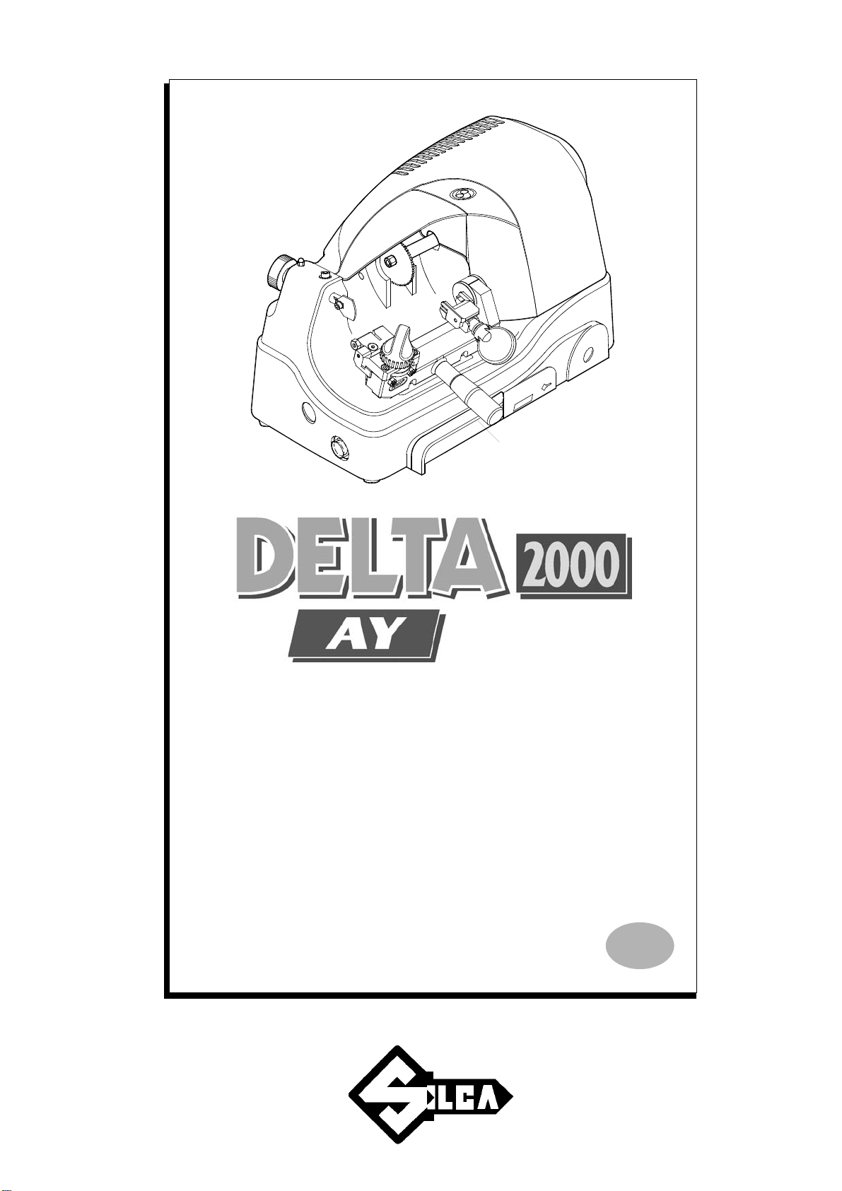
Operating manual
D413450XA
vers.
3.0
E N
®
Page 2

©
This manual has been drawn up by SILCA S.p.A.
All rights reserved. No part of this publication may be reproduced or used in any form or by any means
(photocopying, microfilm or other) without the written permission of SILCA S.p.A.
Edition: march 2008
Printed in Vittorio Veneto
by SILCA S.p.A.
via Podgora, 20 (Z.I.)
31029 VITTORIO VENETO (TV) - Italy
SILCA S.p.A - Vittorio Veneto
1998
Page 3

INDEX
1 TRANSPORT ...................................................................................................3
1.1 Packing .................................................................................................3
1.2 Transport ... ...........................................................................................3
1.3 Unpacking .............................................................................................3
1.4 Machine handling ..................................................................................3
2 WORKING PARTS ..........................................................................................4
3 MACHINE DESCRIPTION ...............................................................................5
3.1 Technical data ......................................................................................6
3.2 Electrical circuit .................................
4 ACCESSORIES PROVIDED ............................................. ... ...........................8
5 MACHINE INSTALLATION and PREPARATION ..........................................9
5.1 Checki
5.2 Environme
5.3 Positioning . .....
5.4 Description of work station ..................................................................10
5.5 Separate parts ....................................................................................10
5.6 Connection to the mains .....................................................................10
ng for damage ............................................................................9
ntal conditions ......................................................................9
......................................................................................9
.........................................7
...........
6 REGULATION and USE of the MACHINE ...................................................
6.1 Checking and setting ..
6.2 Gauging .. ............................................................................................11
6.3 Cutting operations ...............................................................................13
6.4 Key cutting ..........................................................................................13
6.5 Code key-cutting .................................................................................13
7 MAINTENANCE .............................................................................................
7.1 Cutting tool replacement
7.2 Brush replacement ..............................................................................14
7.3 Tracer point replacement ....................................................................15
7.4 Replacing the fuses .........
8 DISPOSAL ....................................................................................................16
9 ASSISTANCE ................................................................................................17
9.1 How to request service .......................................................................17
........................................................................11
.....................................................................14
...........
........................................................15
11
14
Page 4

Page 5
Operating manual - English DELTA 2000 AY
GUIDE TO THE MANUAL
This manual has been produced to serve as a guide for users of the DELT A 2000 AY key-cutting machine. Read it carefully; it is essential if you wish to operate your machine safely and efficiently.
CONSULTATION
The contents of the manual are divided into sections relating to: Ch.
- Transport and handling ......................................................................................................................1
- Description of machine and safety devices ................
- Proper use of the machine..............................................................................................................5-6
- M
aintenance......................................................................................................................................
TECHNICAL TERMS
Common technical t erms are used in this m anual. To assist those wit h little experience of key cutting,
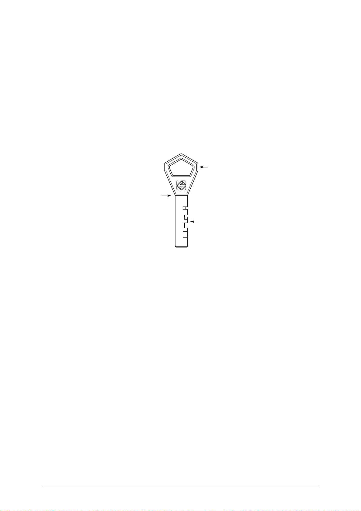
below is an illustration of the terms used for the different parts of keys:
2
............................................................. 2-3-4-5
.7
1
Fig. 1
4
3
1) Head
2) Rim
3) Tip
4) Cuts
Copyright Silca 1 998 1
Page 6
DELTA 2000 AY Operating manual - English
GENERAL INSTRUCTIONS
The DELTA 2000 AY key-cutting machine has been designed according to the specifications of the Machine Directives. From the design stage risks for the operator have been eliminated in all areas: tr ansport, regulation, cutting and maintenance.
The use of protective goggles is compulsory during cutting operat
and in this manual.
The material used in the manufacture of this machine and the components employed during use of the
m
are not dangerous and their use complies with standards.
achine
USE
The DELTA 2000 AY key-cutting machine must be installed and used in the way laid down by the manufacturer, as illustrated in this manual.
If the machine is used differently or for purposes different from those described in this manual, the customer will forego any rights he may have over SILCA S.p.A. Furthermore, unforeseen danger to the operator or any third parties may arise from incorrect use of the machine.
Negligence in the use of the machine or failure on t he part of the operator to observe the instructions
given in this m
such cases.
It is therefore indispensable to read the operating manual carefully in order to make the best use of
the DELTA 2000 AY key-cutting machine and benefit from its potential.
anual are not covered by the guarantee and the manufacturer declines all responsibility in
FURTHER RISKS
There are no further risks arising from the use of the DELTA 2000 AY key-cutting machine.
ions, as indicated on the machine itself
PROTECTION AND SAFETY PRECAUTIONS FOR THE OPERATOR
The DELTA 2000 AY key-cutting machine is built entirely to st andards. The operations for which it has
been designed are easily carried out at no risk to the operator.
The adoption of general safety precautions (use of protective go ggles) and o bservation of the instructions provided by the manufacturer in this manual eliminate all human error, unless deliberate.
The DELTA 2000 AY key-cutting machine is designed with features which make it completely safe in all
its part
s.
• Power supply
The ke y-cutting machine m ust be supp lied with electricity by m eans of a saf ety device (standard with
230V key-cutting machines, on request for other voltages). The plug must be earthed.
• Start-up
The machine is started up by means of:
1) the safety device switch (standard with 230V key-cutting machines);
2) the ON switch, situated on the machine, which activates the machine motor.
• Maintenance
The operations to regulate, service, repair and clean the machine have been devised in the simplest and
safest way possible. There is no danger of removable parts being replaced wrongly or unsafely.
• Machine identification
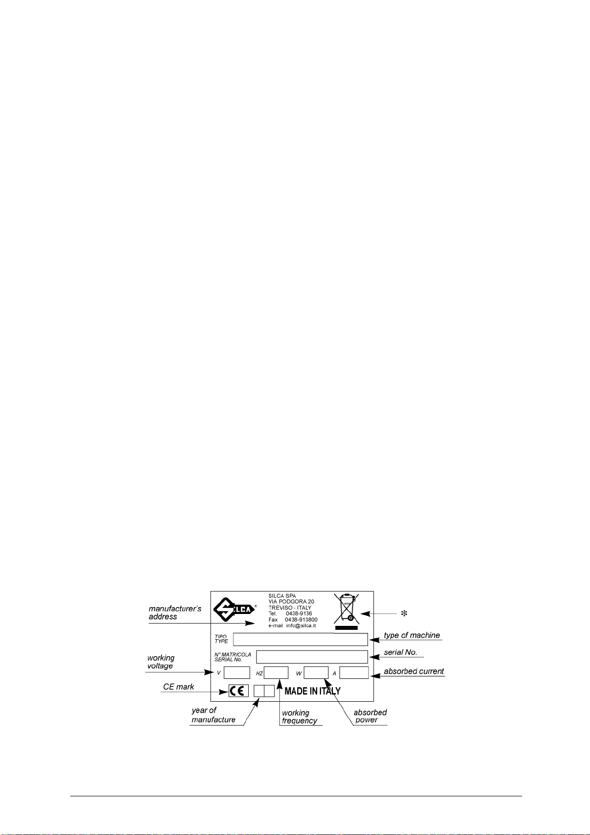
The DELTA 2000 AY is provided with an identification label which shows the serial number (fig. 2).
WARNING: should the machine be left on continuously for over 50 minutes, the cutting tool motor is protect-
ed against overheating and will automatically cut out. In such cases, proceed as follows:
a) turn off the master switch ( D) (fig. 5, page 4);
b) let the motor cool for at least 2 hours before using the machine again.
Fig. 2
2 Copyright Silca 1 998
(*) see chap.8 DISPOSAL, page 16.
Page 7
Operating manual - English DELTA 2000 AY
1 TRANSPORT
The DELTA 2000 AY key-cutting machine is easily transported and is not dangerous to handle.
The packed machine can be carried by one person.
1.1 Packing
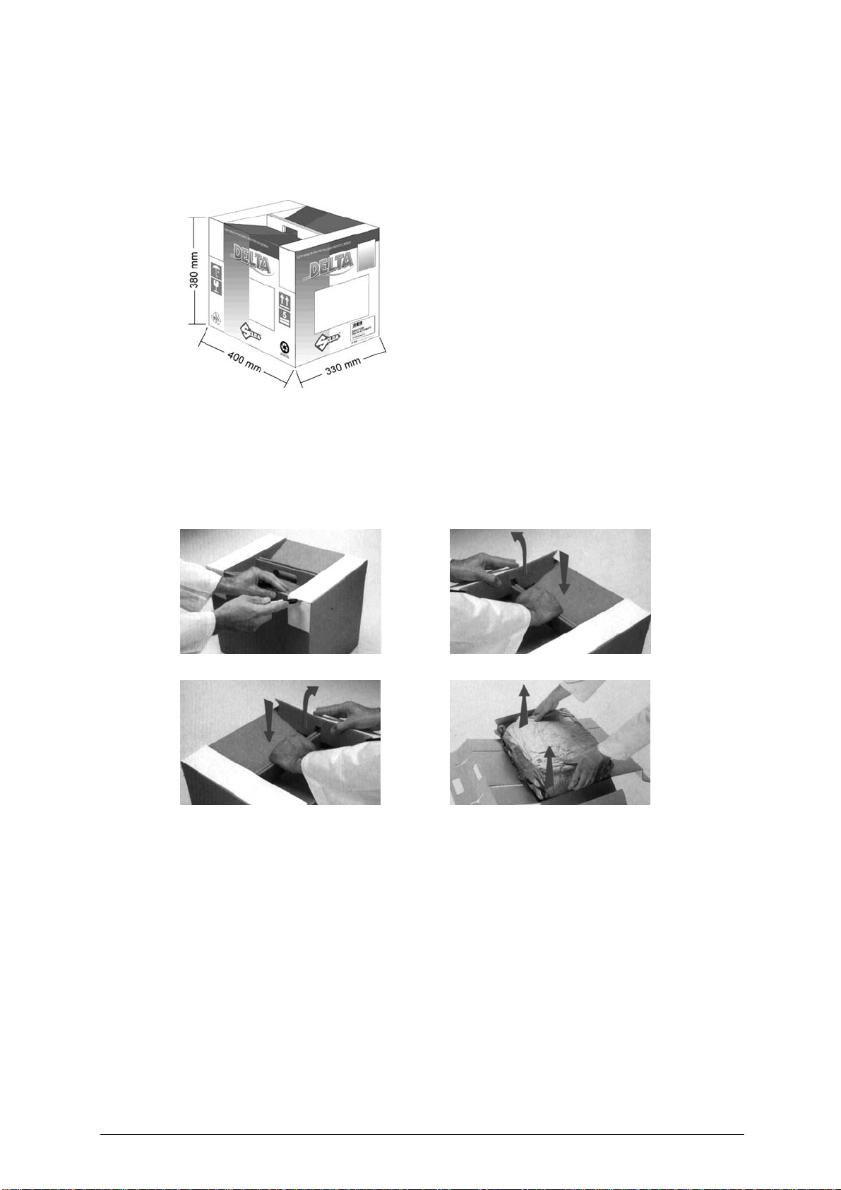
The D ELTA 2000 AY key-cutting machine comes in a st rong
cardboard box, the dimensions of which are shown in fig. 3, designed to protect the machine and all its parts even when it is
stored for long periods.
Fig. 3
1.2 Transport
It is advisable to use the packing every time the machine is transported, as this will avoid knocks which
could cause damage to the machine, persons or things.
1.3 Unpacking
To remove the machine from the packing box, carefully follow the illustrated instructions below:
Fig. 4
Check the contents of the box, which should comprise:
- 1 DELTA 2000 AY key-cutting machine;
- 1 set of documents, including: operating manual, spare parts list and guarantee;
- 1 chippings tray;
- 1 power cable;
- 1 power supply safety device (standard w
- 1 set of accessories.
AB
CD
ith 230V key-cutti
ng machines);
1.4 Machine handling
When the DELTA 2000 AY key-cutting machine has been unpacked, place it directly on its workbench.
This operation can be carried out by one person,
carry the machine.
firmly holding the base, and no other part, to lift and
Copyright Silca 1 998 3
Page 8
DELTA 2000 AY Operating manual - English
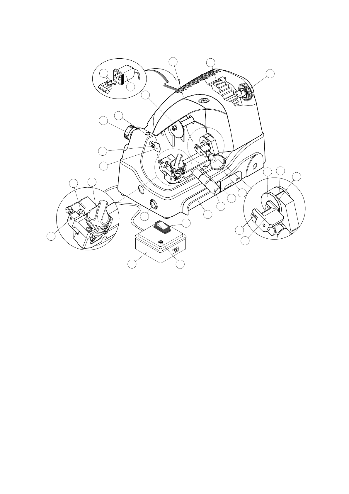
2 WORKING PARTS
H
L
K
G
F3
F2
F1
F
E1
E
E2
D
X1
I
J
A4
A3
A
B
B1
C
A2
A1
A5
Fig. 5
CODED SPACIN G
DEVICE
A - rotating centring clamp knob
A1- rotating centring clamp
A2- jaw
A3- tip stop
A4- coded angle device indicator
A5- coded spacing device drum
B - carriage
B1 - carriage lever handle
C - chippings tray
D - motor/brush start button
E - axis regulation grub screw
E1- axis regulation locking screw
E2- coded spacing device knob
F - tracer point
F1- tracer point locking screw
F2- adjusting nut
F3- tracer point’s group locking screw
G - cutting tool
H - carter
I-motor
J - brush
K - supply socket
L - fuses
X - safety device (standard with 230V key-cutting
X1- safety device main switch
X2- warning light
X
CODED ANGLE
DEVICE
X2
machines, on request for other voltages)
4 Copyright Silca 1 998
Page 9
Operating manual - English DELTA 2000 AY
3 MACHINE DESCRIPTION
DELTA 2000 AY is a professional key-cutting machine for ABLOY keys. The machine comprises the following main parts:
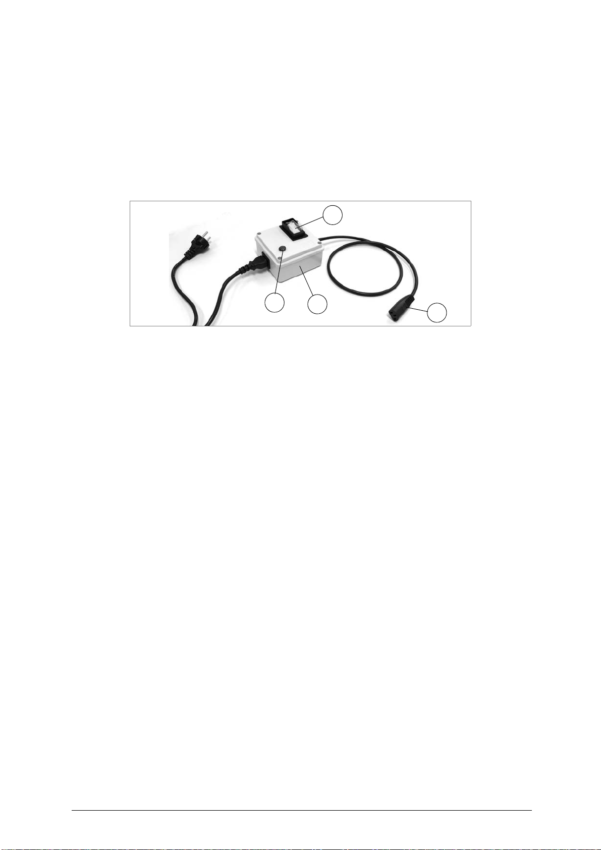
SAFETY DEVICE (X)
The de vice is conne cted to a po wer plug with a differential switch. po wer the key- cutting machine by
pressing the switch (X1).
The warning light (X2) illuminates to indicate voltage in the plug (X3).
WARNING: Switch (X1) is electromagnetic, in the event of a power failure it goes out automatically. When
electricity is restored it must be reset manually to power the machine again by means of the plug
(X3).
X1
X2
Fig. 6
X
MASTER SWITCH (D)
The motor and brush starting button is placed on the left side of the DELTA 2000 AY key-cutting machine.
WARNING: the switch is constantly illuminated to indicate that the machine is live.
MOTOR
The DELTA 2000 AY has a direct drive motor (I). The transmission unit comprises the motor, cutter and
brush and is protected by a single cover (H).
MOBILE UNIT
The mobile unit comprises a carr iage (B) which holds a cod e space setting device and a clamp for securing the keys, with a code device for adjusting inclination (fig. 5, page 4).
The carriage (B) is fitted to the translation shaft and is moved manually by the operator.
It has been designed to avoid the accumulation of cutting dust or chippings.
The key-cutting machine has an inclined table which allow
placed under the carriage and easily removable for thorough cleaning.
• Brush (J)
The brush is used to eliminate burrs caused by the cutting process and is made of safe materials.
• Cutting tool (G)
The cutting tool is the part of the DELTA 2000 AY machine which cuts the key blank. The tool is in HSS
super rapid steel and is protected by a special cover (H) to ensure safe operation.
• Tracer point (F)
The tracer point is housed on the left-hand side of the machine base. Its depth settings are easily regulated with the ring nut (F2).
• Coded angle device
The device comprises:
-a clamp (A1) connected directly to the inclination setting device, which acts as a key
centring device and tip stop;
-a jaw (A2) with which to secure the key, activated by knob (A).
• Coded spacing device
The code device comprises a knob (E2) to activate a graduated slide which determines the position of
the various cuts.
s the chi
ppings to collect in the special tray (C)
X3
Copyright Silca 1 998 5
Page 10

DELTA 2000 AY Operating manual - English
3.1 Technical data
ELECTRICAL PROPERTIES: 230V - 50Hz 190W 1,5A
CUTTING TOOL: Super Rapid Steel (HSS)
MOTOR: One speed single phase 230V-50Hz 1350 rpm 0,145 Kw
SAFETY DEVICE: standard with 230V key-cutting machines, on request for other voltages
CLAMP: rocker
CARRIAGE MOVEMENT: manual
CARRIAGE RUN: (maximum length of cuts): 23 mm
DIMENSIONS: width: 210 mm depth: 370 mm height: 250 mm
CUTTING NOISE: Lp (A)= 92,2 dB (A)
NOISE POTENTIAL: Lw (A)= 104,9 dB (A)
WEIGHT: Kg. 14
6 Copyright Silca 1 998
Page 11
Operating manual - English DELTA 2000 AY
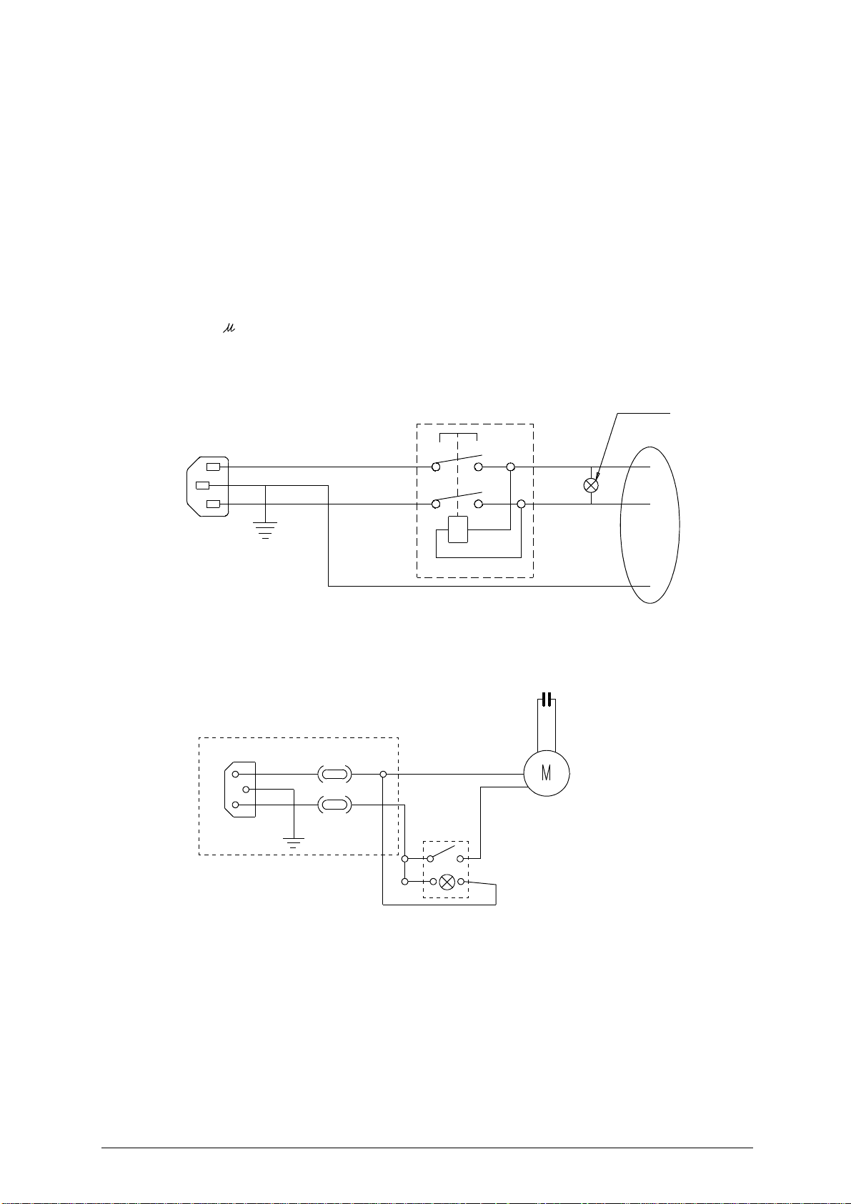
3.2 Electrical circuit
The DELTA 2000 AY key-cutting machine is provided with a motor which performs at 1350 rpm with consumption of approx. 0,19 kw and absorption of 1,5A.
The main parts of the electrical circuit are listed below:
1) Safety device inlet
2) Safety main switch
3) Warning light
4) Wiring clip
5) Machine inlet
6) Rapid 3,15A fuses
7) Switch with lamp
8) Motor: 230V a.c. 50Hz
9) 6,3 F condenser
Safety device
2
brown
1
yellow-green
light blue
brown
light blue
3
4
IN
OUT
9
machine inlet
6
8
5
6
motor
7
Copyright Silca 1 998 7
Page 12
DELTA 2000 AY Operating manual - English
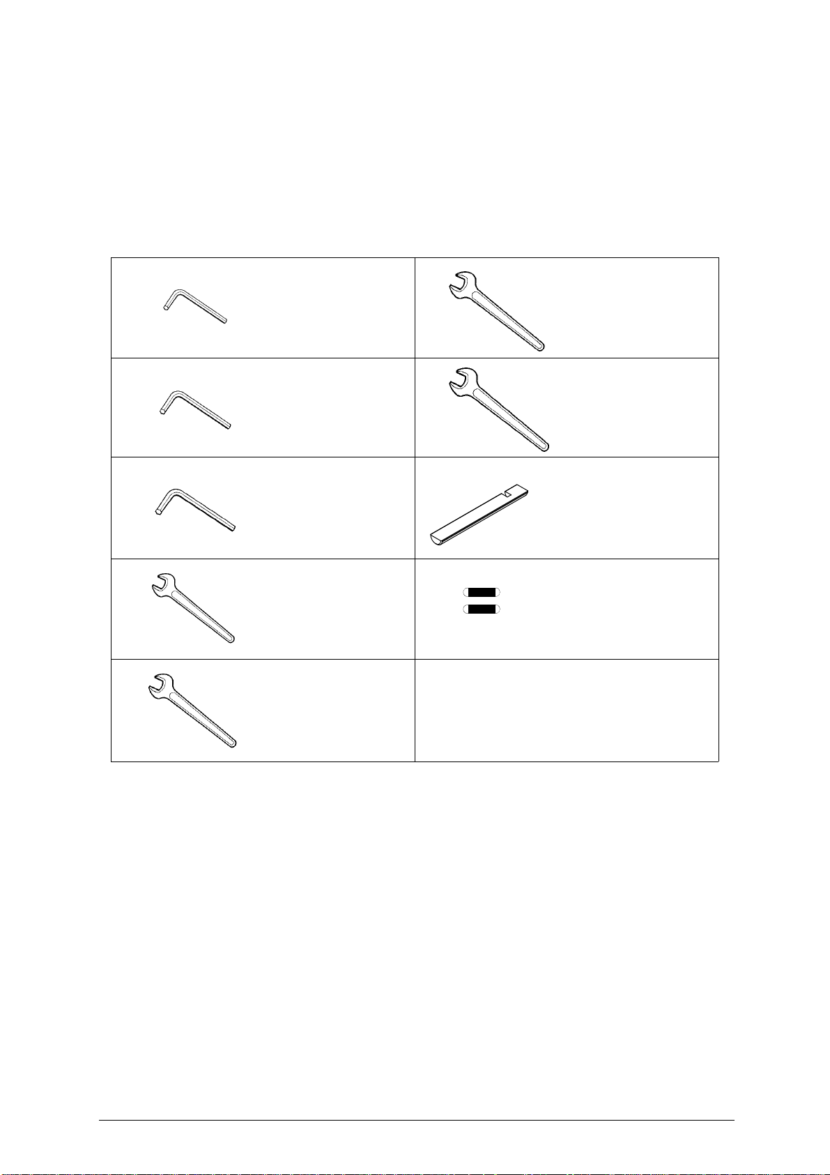
4 ACCESSORIES PROVIDED
To ensure trouble-free working with t he DELTA 2000 AY, it is advisab le to always ha ve certain spare
parts on hand.
It is advisable to always have a tool box containing: tools, cutting tools, brushes and small replacement
parts.
DELTA 2000 AY is su pplied with a full range of accessories. Th e accessories provided by Silca are all
that i
ecessary to carry out the operations for which the machine is designed.
s n
1
2
3
4
5
code D300222ZZ
2,5 mm ALLEN KEY
code D300223ZZ
3 mm ALLEN KEY
code D300224ZZ
4 mm ALLEN KEY
code D302883ZZ
8 mm SPANNER
code D300308ZZ
10 mm SPANNER
6
7
8
9
code D312327ZZ
15 mm SPANNER
code D301760ZZ
17 mm SPANNER
code D403587BA
GAUGING CALLIPER
code D309226ZZ
5X20 FUSES (2 pcs)
3,15 Amps rapid
8 Copyright Silca 1 998
Page 13
Operating manual - English DELTA 2000 AY
5 MACHINE INSTALLATION AND PREPARATION
The DELTA 2000 AY key-cutting machine can be installed by the pu rchaser and does not require any
special skills. However, some checks and preparation for use need to be carried out by the operator.
5.1 Checking for damage
The DELTA 2000 AY is solid and compact and will not normally damage if transport, unpacking and installation have all been carried out according to the instructions on the packing box.
However, it is always advisable to check that the machine has not suffered any damage.
5.2 Environmental conditions
To ensure that the be st use is m ade of t he key-cutting machine, certain parameters must be bo rne in
mind:
- damp, badly ventilated sites should be avoided.
- the conditions for the machine are:
temperature:
relative humidity:
5.3 Positioning
Place the machine on a horizontal surface, solid enough to take the weight (14 Kg).
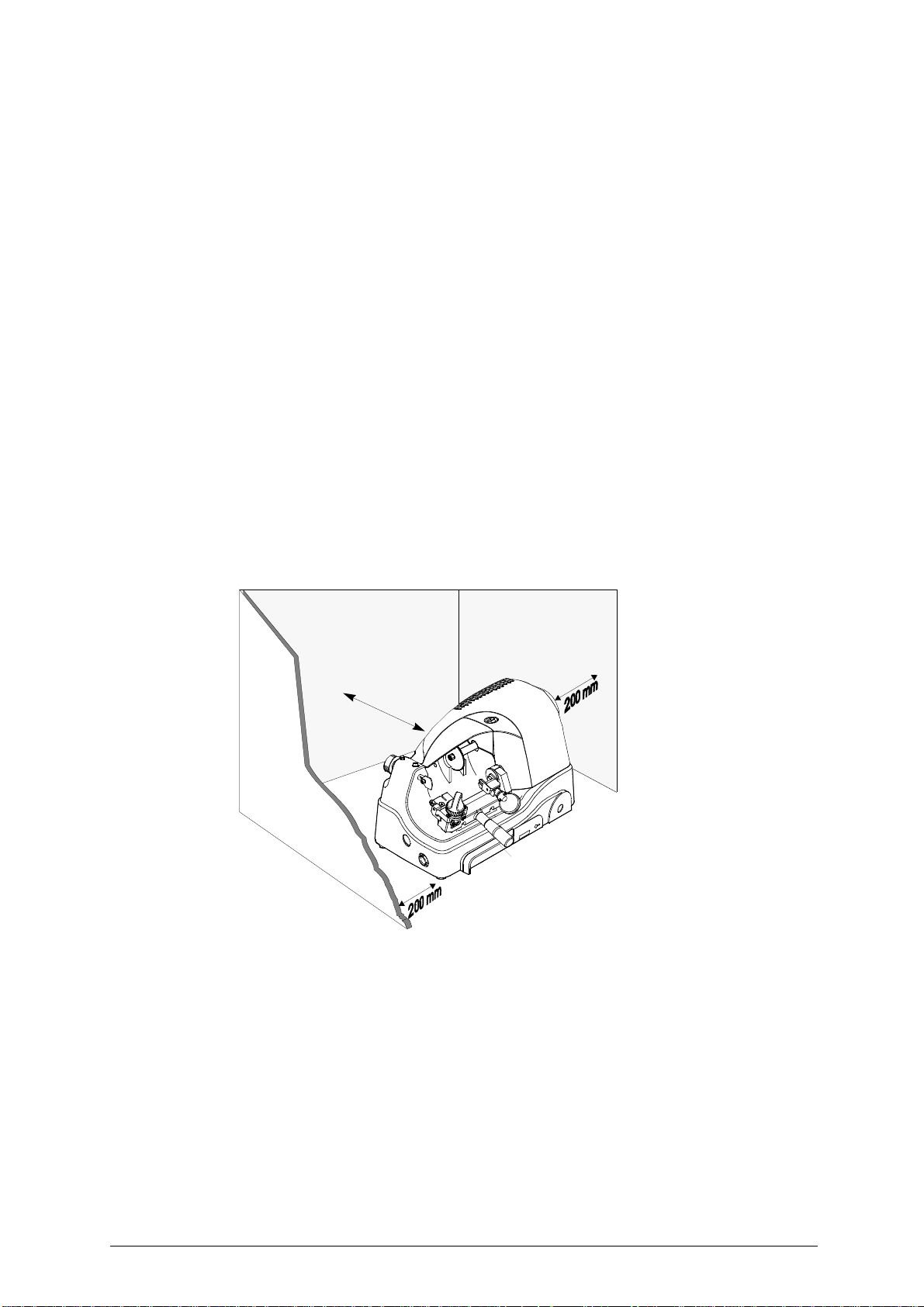
To facilitate operation and maintenance, install the machine with a cl earance of at least 200 mm on all
sides (fig
Check that the weight of the machine is evenly distributed over the four feet; horizontal positioning prevents vibrations during operation.
WARNING: ensure that the machine voltage is the same as that of the mains, which must be properly earthed
and provided with a differential switch.
. 7).
between 0 and 40°C
approx. 60%
Fig. 7
2
0
0
m
m
Copyright Silca 1 998 9
Page 14
DELTA 2000 AY Operating manual - English
5.4 Description of work station
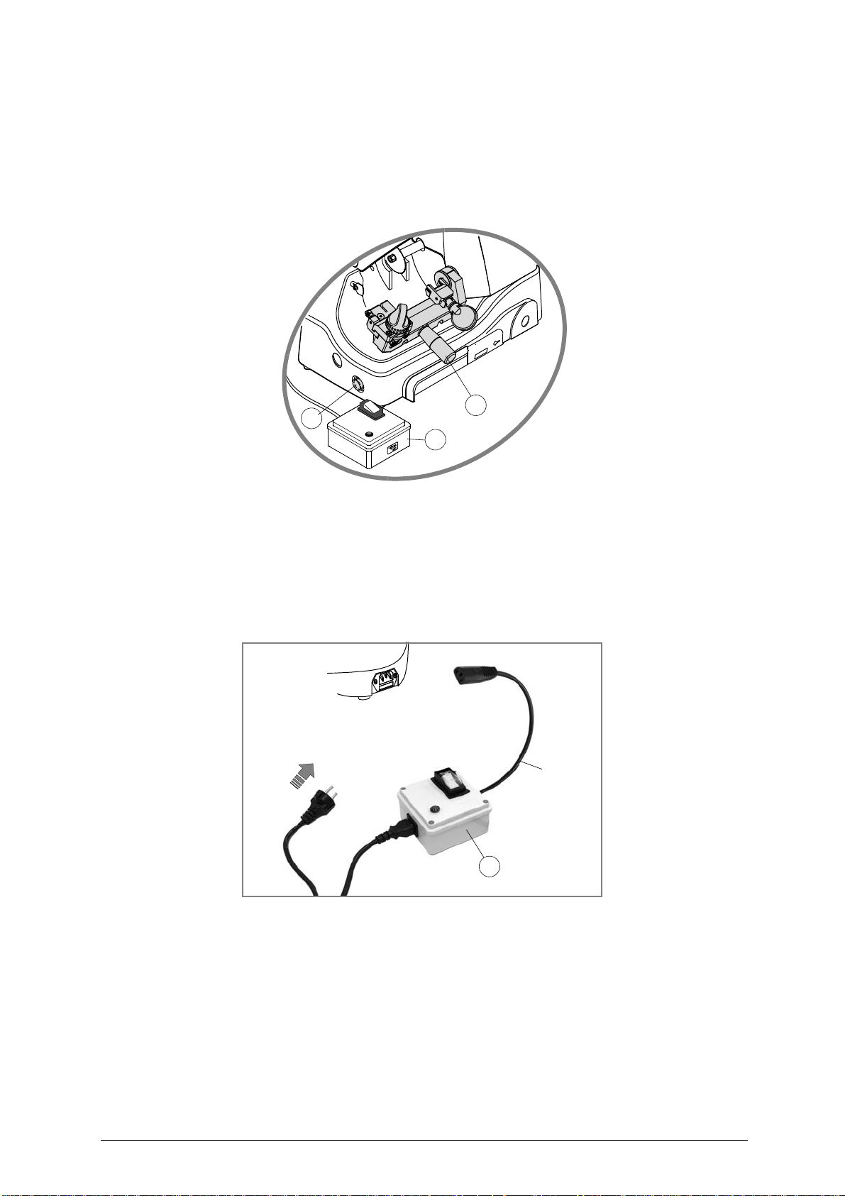
The machine needs only one operator, who has the following controls at his/her disposal (fig. 8):
• Safety device (X).
• Master switch (D), placed on the left-hand side of the machine; provide
indicating that the machine is live.
• Carriage lever handle (B1).
d with a warning light
Fig. 8
5.5 Separate parts
The detachable parts of the machine are packed separately and must be fitted to the DELTA 2000 AY
by the operator, as follows:
POWER CABLE
First connect the safety device (X) to the key-cutting machine and the power cable then connect the free
end of the power cable to the power mains (fig. 9).
D
power
mains
B1
X
power
cable
Fig. 9
5.6 Connection to the mains
It is extremely important for the operator’s safety to ensure that the key-cutting machine is connected to
the power mains with the right voltage and
10 Copyright Silca 1 998
by means of a properly earthed differential switch.
X
Page 15
Operating manual - English DELTA 2000 AY
6 REGULATION AND USE OF THE MACHINE
6.1 Checking and setting
The cutting tool on the DELTA 2000 AY is used to cut the key blanks and must be periodically checked
and replaced.
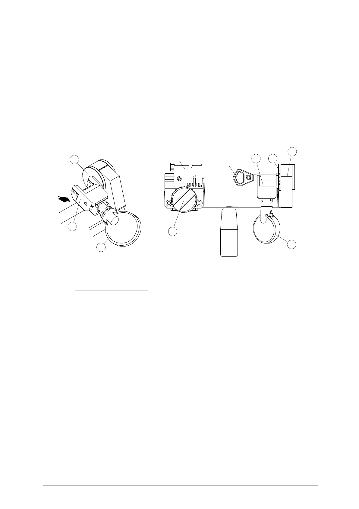
Periodically, and whenever the cutting tool is replaced, check the
perfect machine efficiency.
AB
Fig. 10
6.2 Gauging
AXIAL GAUGING
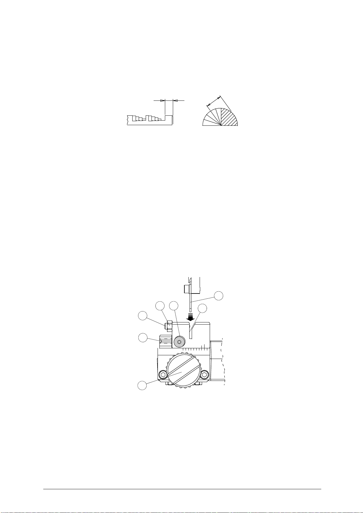
Axial gauging is regulation of the position of the cutting spaces (fig. 10 - A).
AXIAL GAUGING REGULATION
To regulate the axial gauging, proceed as follows:
WARNING: disconnect the machine from the mains.
1) set up the coded spacing device (fig. 5, page 4) by means of the knob (E2) so that the indicator "5"
is aligned with position "2" (fig. 11).
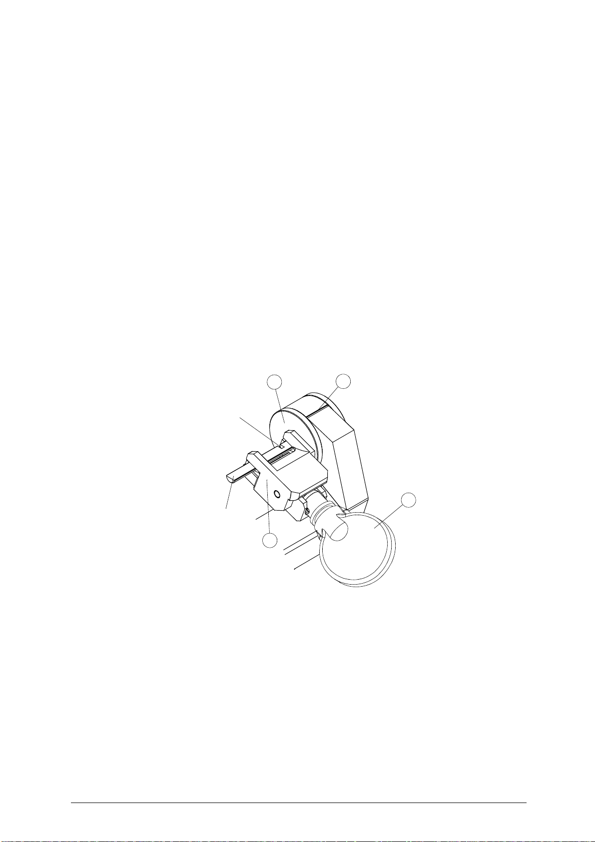
2) place the gauging calliper provided in the clamp (A1) (fig. 12), pushing towards the side of the tip stop
(A3), and secure by turning the knob (A).
3) take the carriage towards the cutting tool and place the tracer point (F) all the way into the locating
groove (
4) check that the cutting tool enters clearly into the groove in the gauging caliper (fig. 12). If adjustment
is necessary, loosen screw (E1) and adjust axial
5) when gauging is complete, tighten the screw (E1) well.
(fig. 11).
E3)
key-cutting m
gauging by means of the grub screw (E).
achine settings, to ensure
Fig. 11
E2
F
E1
O
N
E
E3
3
5
2
Copyright Silca 1 998 11
Page 16
DEPTH SETTING
Depth setting is regulation of the cutting depth (fig. 10 - B). Usually depth setting is not necessary during
normal use of the machine. However, if the tracer point is replaced o r an optional carriage is used it is
advisable to
check the depth settings.
REGULATING DEPTH SETTING
To regulate the depth settings, proceed as follows:
WARNING: disconnect the machine from the mains.
1) set up the cod ed spacing device by means of the knob (E2) so that the indicator "5" is aligned with
position "2" (fig. 11).
2) insert the tip of the gauging calliper (provided) into the rotating clamp (A1) (fig. 12), push up against
the tip stop (A3) and lock in the calliper by turning the knob (A).
3) take the carriage towards the cutting tool and place the tracer point (F) all the way into the locating
groove (
4) check that the cutting tool enters clearly into the groove in the gauging calliper (fig. 12). If adjustment
is necessary, adjust axial gauging in the way described above ("Axial gauging regulation").
5) loosen the screw (F3) locking the tracer point unit (fig. 5, page 4).
6) use the lateral brush (J) to turn the cutting tool shaft in the opposite direction to cutting. The cutting
tool shou
pag. 4) clockwise to move the cutting tool unit forward, or in the opposite direction to move it back.
7) when regulation is complete, screw down the screw (F3) to lock the tracer point’s group.
8) if the height of the tracer point must be adjusted, loosen screw (F1) and re-position manually.
9) when the ideal regulation has been reached, tighten the tracer point locking screw (F1).
10) if an optional carriage is used, check that the tracer point enters freely into the locating groove (E3)
(fig. 11 ) and that t here is not excessive play on it . If necessary, adjust play b etween the locat ing
groove and tracer point by loosening the nut (O) and turning
complete, tighten the nut (O).
(fig. 11).
E3)
ld skim
the bottom of the groove on the gauging caliper. If not, turn the ring nut (F2) (fig. 5,
A3
A4
the g
rub screw (N). When adjustment is
Fig. 12
groove
A
gauging
calliper
A1
12 Copyright Silca 1 998
Page 17
Operating manual - English DELTA 2000 AY
6.3 Cutting operations
WARNING: to work in complete safety, pay special attention to the following recommendations:
• Always work with dry hands.
• Check that the machine is properly earthed.
• Use the protective goggles, even if the cutting tool is fitte
• Start the motor only when all the operations with the carriage
keys, etc.).
• Keep hands away from the cutting tool when in motion.
d with a protective shield.
have been carried out (securing
6.4 Key cutting
PLACING KEYS INTO CLAMP
Place the key blank into the clamp, pushing against the side of the tip stop (A3), and secure by turning the knob
(A) (Fig. 13).
A3
A1
A
Fig. 13
6.5 Code key-cutting
N.B.: ABLOY keys can feature two types of cut which differ only in the distance between the
first cut and the tip of the key. This distance can be 3 or 5 mm (fig. 10-A). To cut keys with 3 mm
use mark 3 on the locator (Fig. 11) as a reference for positioning the key. For 5 mm keys, use
mark 5.
To code cut a key blank proceed as follows:
1) set the cutting position on the space code device by m
knob (A) to turn the rotating clamp (A1) until the code for the inclinations marked on the drum (A5) is
aligned wi
2) activate the machine by pressing the m
3) move the carriage towards the cutting tool, making sure that the tracer point slides right into the notch
on the locator (fig. 13)
4) go on to the following position and repeat the cutting operation with the corresponding code, and so
on until the key has been cut.
5) pull the carriage back, turn off the machine, loosen the clamp (A1) and remove the key.
th the indicator (A4).
locator
key blank
E2AE2
eans of knob (E2) (fig. 13). Exert pressure on
otor/brush start switch (D)
. Make the cut and pull back the carriage.
A4
A1 A5
(fig. 5, pag. 4).
Copyright Silca 1 998 13
Page 18
DELTA 2000 AY Operating manual - English
7 MAINTENANCE
WARNING: for repairs or replacement of parts for maintenance, the ‘CE’ mark is guaranteed only if original
spare parts provided by the manufacturer are used.
Although the DELTA 2000 AY key-cutting machine does not require special maintenance, it is advisable
to check and, if necessary, replace the parts subject to wear (cutting tool, brush, tracer point).
Replacement is simple and can be carried out by the operator.
CLEANING
cutting operations.
WARNING: DO NOT USE COMPRESSED AIR!
WARNING: to keep the machine well maintained we recommend using protective oil, e.g. WD40 or similar,
applied to the bu
(clamps, guides, carriages, etc.).
Before starting any type of maintenance (checks or replacements), read the instructions below:
• never carry out maintenance or servicing with the machine switched on.
• always remove the mains plug.
• follow all the instructions in the manual to the letter.
• use original spare parts.
• always check that any screws or nuts removed when
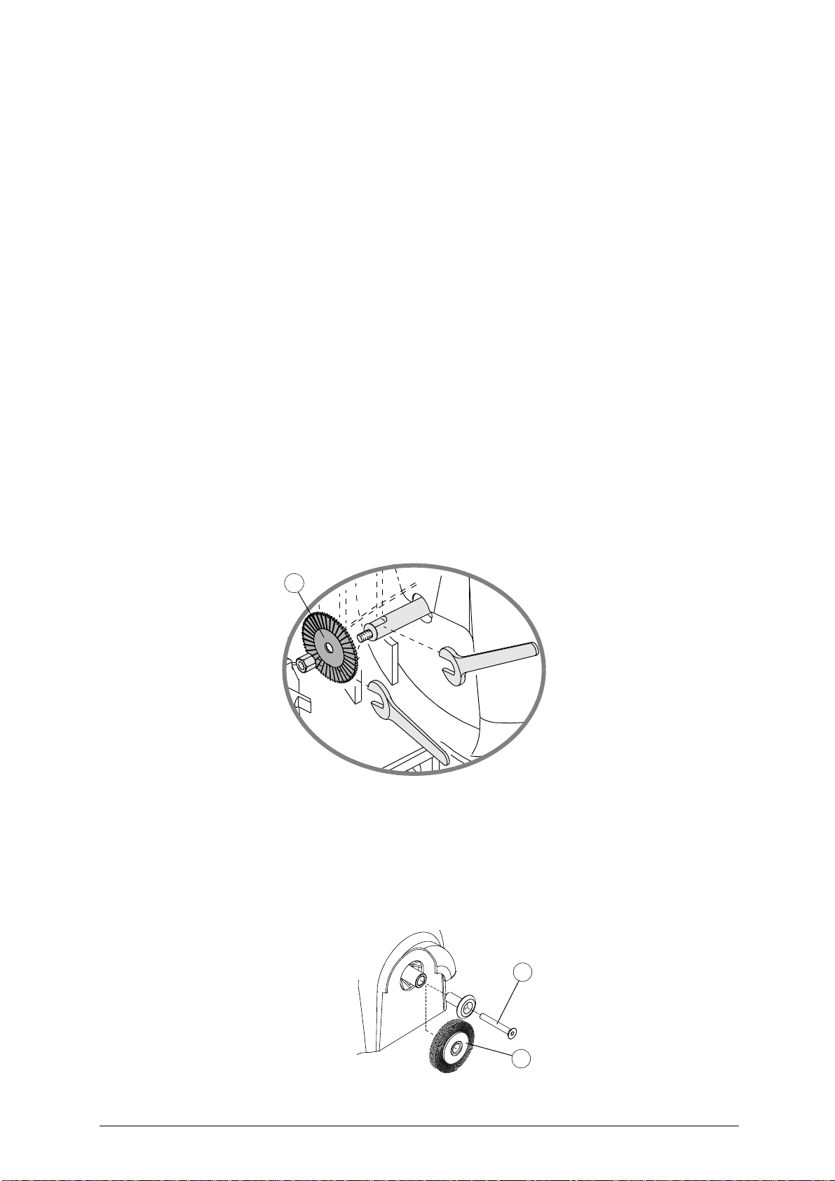
7.1 Cutting tool replacement
It is not necessary to remove the protective shield in order to replace the cutting tool (G).
WARNING: unplug the machine from the mains.
1) place the spanner provided in position on the motor shaft (fig. 14);
2) use a suitable spanner to loosen the new cutting tool locking nut.
WARNING: the thread is left-handed.
3) replace the cutting tool after cleaning its seat;
4) install the new cutting tool and tighten the nut.
WARNING:
the tool rotates clockwise.
: it is advisable to use a soft brush to keep the carriage and cl amps free of chippings from
rnished mechanical parts. This prevents oxidation of the parts in question
replacing
a piece are properly tightened.
G
Fig. 14
7.2 Brush replacement
When the brush (J) is no longer effective it must be replaced, as follows:
WARNING: unplug the machine from the mains.
1) place the spanner provided in position on the motor shaft (fig. 14);
2) use the wrench provided to loosen the brush locking screw (X) (fig. 15);
3) replace the brush and secure with the screw (X);
4) remove the spanner from the motor shaft.
X
Fig. 15
14 Copyright Silca 1 998
J
Page 19
Operating manual - English DELTA 2000 AY
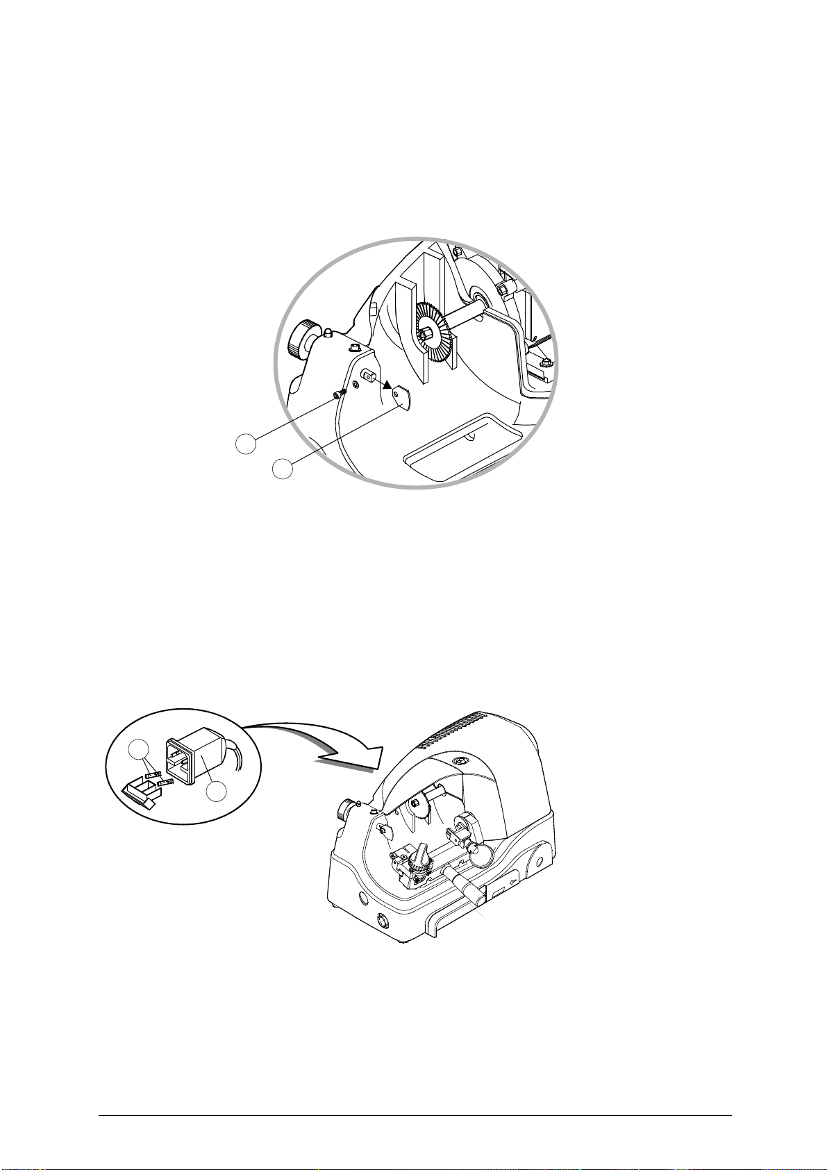
7.3 Tracer point replacement
To replace the tracer point (F), proceed as follows (fig. 16):
WARNING: unplug the machine from the mains.
1) loosen and remove the tracer point locking screw (F1).
2) remove the tracer point.
3) fit the new tracer point.
4) re-gauge the machine as described in (Ch. 6, page 11).
F1
F
Fig. 16
7.4 Replacing the fuses
WARNING: unplug the machine from the mains.
1) detach the wiring from the machine plug;
2) turn the key-cutting machine so that the fuse box is easily reached;
3) remove the fuse box placed below the power inlet (K) (fig. 17);
4) replace the fuses (L);
5) close the fuse box and connect the power cable.
WARNING: the fuses must both be of the same type (rapid) and with the same amps (3,15 Ampere)
L
K
Fig. 17
Copyright Silca 1 998 15
Page 20

DELTA 2000 AY Operating manual - English
8DISPOSAL
For correct disposal please refer to current standards.
INFORMATION FOR USERS OF PROFESSIONAL EQUIPMENT
From "Actuation of Directive 2012/19/EU regarding Waste Electrical and Electronic Equipment (WEEE)"
The symbol of a crossed waste bin found on equipment or its packing indicates that at the end of the
product’s useful life it must be collected separately from other waste so that it can be properly treated
and recycled.
In particular, separate collection of this professional equipm ent when no longer in use is organised and
managed:
a) directly by the user when the equipment was placed on the market before 31 December 2010 and the
user personally decides to eliminate it without replacing it with new equivalent equipment designed for
the same use;
b) by the manufacturer, that is to say the subject which was the first to introdu ce and market new equip-
ment that replaces previous equipment, when the user decides to eliminate equipment placed on the
market before 31 December 2010 at the end of its useful life and replace it with an equivalent product
designed for the same use. In this latter case the user may ask the manufacturer to collect the existing
equipment;
c) by the manufacturer, that is to say the subject which was the first to introduce and market new equip-
ment that replaces previous equipment, if it was placed on the market after 31 December 2010;
Suitable separate collection for the purpose of fo rwarding disca rded equi pment for recycli ng, treatm ent
or disposal in an environmentally friendly way helps to avoid possible negative effects on the
environment and human health and enco urages re-use a nd/or recycling of the ma terials making up the
equipment.
The sanctions currently provided for by law shall apply to users who dispose of products in unauthorised
.
ways
16 Copyright Silca 1998
Page 21

Operating manual - English DELTA 2000 AY
9 ASSISTANCE
Silca provides full assistance to purchasers of the DELTA 2000 AY key-cutting machine.
To ensure complete safety for the operator, any job not specified in this manual should be carried out by
the manufacturer
On the back cover of this manual is a list of the manufacturer’s addresses; listed below are the addresses
of specialised Service Centres.
9.1 How to request service
The guarantee attached to DELT A 2000 AY ke y-cutting machine ensures free repairs or replacements
of faulty parts within 24 months of purchase. All other service calls must be arrange d by the cu stomer
with Silca or with a Silca Service Centre.
or in the special Service Centres recommended by Silca.
Copyright Silca 1 998 17
Page 22
VITTORIO VENETO 24/03/2011
CE DECLARATION OF MACHINE COMPLIANCE
SILCA S.p.A. - VIA PODGORA 20 ( Z.I.)
31029 VITTORIO VENETO (TV) - (ITALY)
TEL. 0438 9136 - FAX. 0438 913800
Declares under its own responsibility that the Key-cutting machine model
DELTA AY
complies with the requirements of the following European Directives:
European Union DIRECTIVE 2006/42/CE (Machines)
and with the EN 292/1 – EN 292/2 Standards
European Union DIRECTIVE 2004/108/CE
and with the EN 55022 - IEC 801-2 - IEC 801-4 Standards
(Electromagnetic Compatibility)
European Union DIRECTIVE 2006/95/CE
and with the EN 60204-1 - EN 60950 Standards
Claudio Tomasella of the Silca S.p.A. Research & Development Division is authorized
to create a Technical File.
General Manager Basic Production Center
(Low Voltage) | 97 |
Page 23

SILCA S.p.A.
Via Podgora, 20 (Z.I.)
31029 VITTORIO VENETO (TV)
Tel. 0438 9136 Fax 0438 913800
E-mail: [email protected]
www.silca.biz
Members of the Kaba Group
 Loading...