

Silca Crown D422143XA Operating Manual
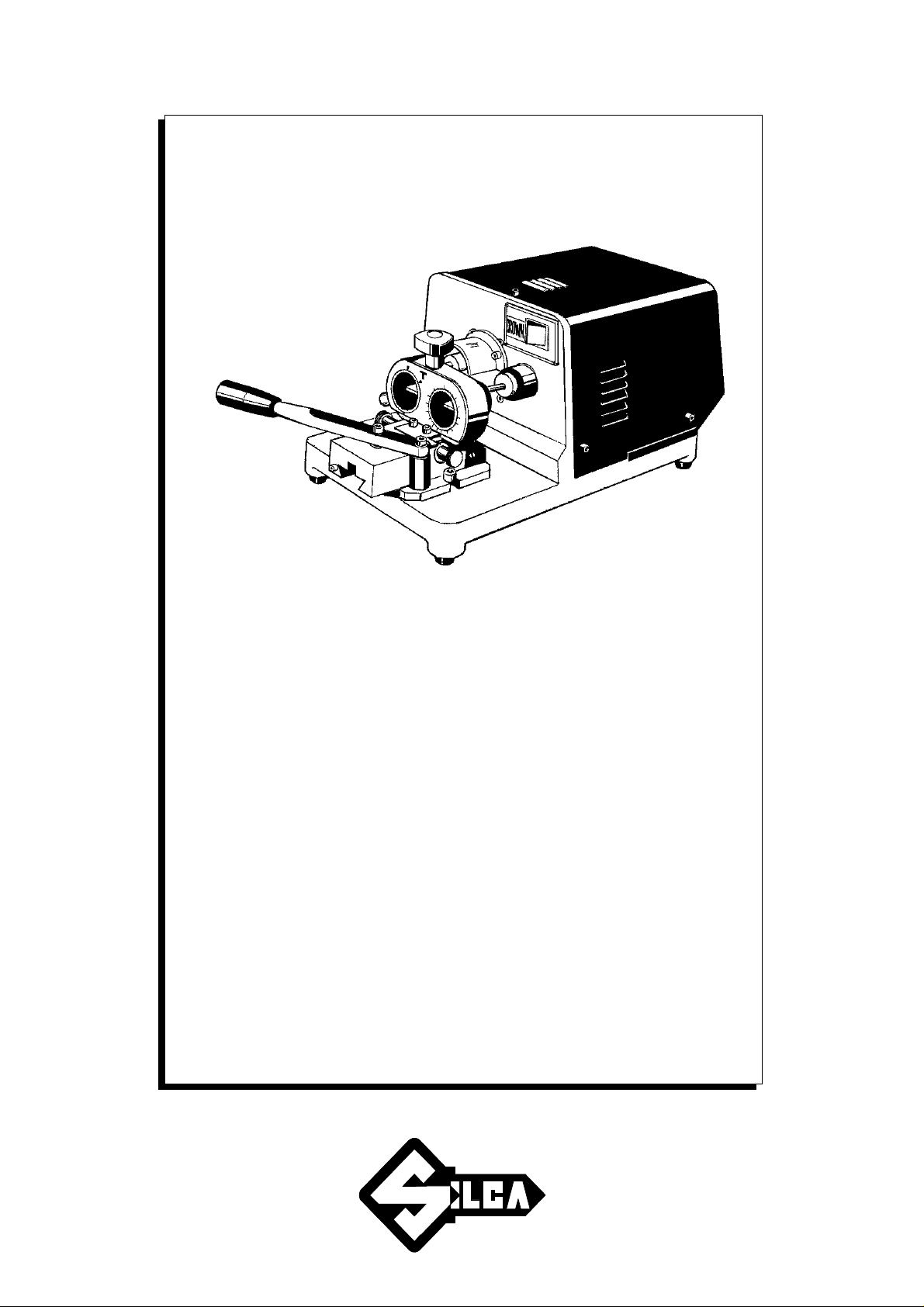
CROWN
CROWN
Operating manual
D422143XA
vers.
1.0
®

© 2001 SILCA S.p.A - Vittorio Veneto
This manual has been drawn up by SILCA S.p.A.
All rights reserved. No part of this publication may be reproduced or used in any form or by any means (photocopying,
microfilm or other) without the written permission of SILCA S.p.A.
published in october 2001
Printed in Vittorio Veneto
by SILCA S.p.A.
via Podgora, 20 (Z.I.)
31029 VITTORIO VENETO (TV) - Italy

INDEX
1
TRANSPORT ..............................................................................................................3
1.1 Packing ............................................................................................................3
1.2 Transport .........................................................................................................3
1.3 Unpacking ........................................................................................................3
1.4 Machine handling .............................................................................................3
2
WORKING PARTS .....................................................................................................4
3
MACHINE DESCRIPTION ..........................................................................................5
3.1 Technical data .................................................................................................6
3.2 Electrical circuit ................................................................................................6
4
ACCESSORIES PROVIDED ......................................................................................7
5
MACHINE INSTALLATION AND PREPARATION ....................................................8
5.1 Checking for damage .......................................................................................8
5.2 Environmental conditions .................................................................................8
5.3 Positioning .......................................................................................................8
5.4 Description of work station ...............................................................................9
5.5 Separate parts .................................................................................................9
5.6 Connection to the mains ..................................................................................9
6
REGULATION AND USE OF THE MACHINE .........................................................10
6.1 Control and gauging ......................................................................................10
6.2 Gauging .........................................................................................................10
6.3 Cutting operations ..........................................................................................11
7
MAINTENANCE ........................................................................................................12
7.1 Cutter replacement ........................................................................................12
7.2 Tracer point replacement ...............................................................................12
7.3 Replacing the fuses .......................................................................................12
8
WASTE DISPOSAL ..................................................................................................13
9
ASSISTANCE ...........................................................................................................14
9.1 How to request service ..................................................................................14
10
SYNCHRONISED DEVICES ....................................................................................15
10.1 Devices T2 - T3 - T4 - T5 - T6 - T7 - T8 - T9 - T13 ........................................16
10.2 Self-Centering Device T10 .............................................................................17
10.3 Self-Centering Device T15 .............................................................................20
10.4 T14 synchronised device for cutting 5VP3 keys ............................................22
10.5 T17 Synchronised device ..............................................................................23


Operating manual - English CROWN
GUIDE TO THE MANUAL
This manualhas been produced to serveas a guide forusers of the CROWN key-cuttingmachine. Read
it carefully; it is essential if you wish to operate your machine safely and efficiently.
C
ONSULTATION
The contents of the manual are divided into sections relating to: Chapter
- Transport and handling ................................................................................................................... 1
- Description of machine and safety devices .......................................................................... 2-3-4-5
- Proper use of the machine .......................................................................................................... 5-6
- Maintenance .................................................................................................................................. 7
- Optional devices ........................................................................................................................... 10
Copyright Silca 2001 1
CROWN Operating manual - English
GENERAL INSTRUCTIONS
The CROWN key-cutting machine has been designed according to the specifications of the Machine
Directives. From the design stage risks for the operator have been eliminated in all areas: transport,
regulation, cutting and maintenance.
The use of protective goggles is compulsory during cutting operations, as indicated on the machine
itself and in this manual.
The material used in the manufacture of this machine and the components employed during use of
the machine are not dangerous and their use complies with standards.
U
SE
The CROWNkey-cutting machine must be installed and used in the way laid down by the manufacturer,
as illustrated in this manual.
If the machine is used differently or for purposes different from those described in this manual, the
customer will forego any rights he may have over SILCA S.p.A. Furthermore, unforeseen danger to the
operator or any third parties may arise from incorrect use of the machine.
Negligence in the use of the machine or failure on the part of the operator to observe the instructions
given in this manual are not covered by the guarantee and the manufacturer declines all responsibility
in such cases.
It is therefore indispensable to read the operating manual carefully in order to make the best use
of the CROWN key-cutting machine and benefit from its potential.
F
URTHER RISKS
There are no further risks arising from the use of the CROWN key-cutting machine.
P
ROTECTION AND SAFETY PRECAUTIONS FOR THE OPERATOR
The CROWN key-cutting machine is built entirely to standards. The operations for which it has been
designed are easily carried out at no risk to the operator.
The adoption of general safety precautions (use of protective goggles) and observation of the
instructions provided by the manufacturer in this manual eliminate all human error, unless deliberate.
The CROWN key-cutting machine is designed with features which make it completely safe in all its
parts.
• Power supply
The key-cutting machine must be supplied with electricity. The plug must be earthed.
• Start-up
The machine is started up:
- by means of the START button on the safety device (standard with 230V key-cutting machines, on
request for other voltages);
- by means of the master switch.
• Operation
The machine is started up by means of a motor switch.
• Maintenance
The operations to regulate, service, repair and clean the machine have been devised in the simplest
and safest way possible. There is no danger of removable parts being replaced wrongly or unsafely.
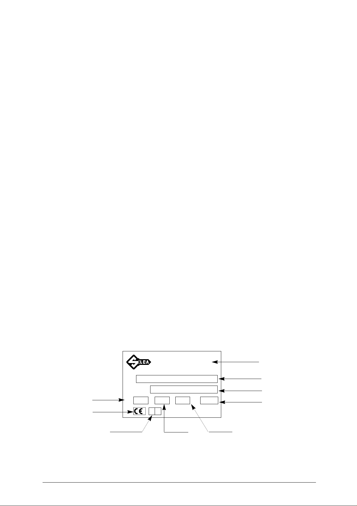
• machine identification
The CROWN is provided with an identification label which shows the serial number (fig. 1).
Manufacturer’s
identity
Type of machine
Serial No.
Absorbed power
Working
voltage
CE mark
TIPO
TYPE
N˚ MATRICOLA
SERIAL No.
VOLT
SILCA S.p.A. - Via Podgora 20 (Z.I.)
®
31029 VITTORIO VENETO (TV) ITALY
(0438) 9136
☎
Telefax (0438) 913800
Telex 410579 SILCA I
Hz. WATT
A.
Year of
manufacture
Fig. 1
Working
frequency
2 Copyright Silca 2001
Absorbed
current
Operating manual - English CROWN
1 TRANSPORT
The CROWN key-cutting machine is easily transported and is not dangerous to handle.
The packed machine can be carried by one person.
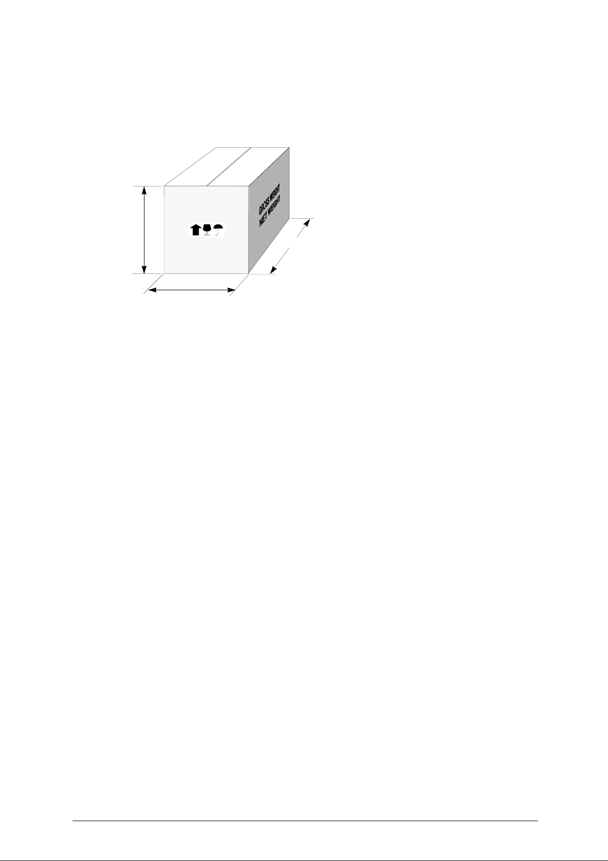
1.1 Packing
350 mm
Fig. 2
1.2 Transport
It is advisable to use the packing every time the machine is transported, as this will avoid knocks which
could cause damage to the machine, persons or things.
1.3 Unpacking
To remove the machine from the packing box:
1) cut the straps with scissors and remove.
2) prise off the staples
3) open the box without damaging it as it may be used again (e.g. removals, dispatch to the manufacturers for repairs or servicing).
4) check the contents of the box, which should comprise:
350 mm
530 mm
- 1 CROWN key-cutting machine
- 1 set of documents, including: operating manual, spare parts list and guarantee
- 1 set of accessories
- 1 power cable
1.4 Machine handling
When the CROWN key-cutting machine has been unpacked, place it directly on its workbench.
This operation can be carried out by one person, firmly holding the base, and no other part, to lift
and carry the machine.
Copyright Silca 2001 3
CROWN Operating manual - English
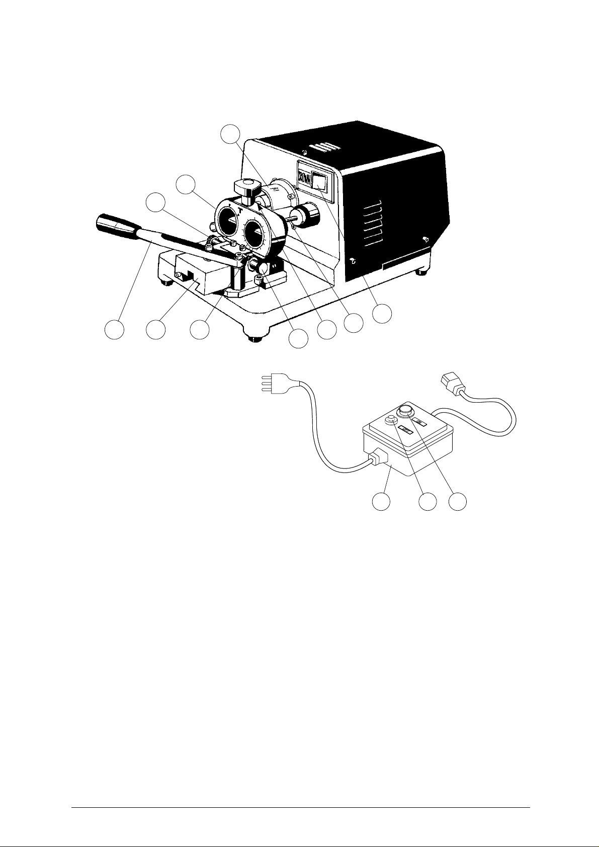
2 WORKING PARTS
D
L
G1
A
B
EF H
C
G
Fig. 3
S RQ
A - Master switch
B - Tracer point
C - Cutter
D - Safety screen
E - Slide
F - Lever
G - Height adjusting screw
G1- Wedge locking knob
H - Wedge
L - Synchronised device (optional)
Q - Safety device
R - START button
S - STOP button
4 Copyright Silca 2001

Operating manual - English CROWN
3 MACHINE DESCRIPTION
The CROWNis a professionalmachinedesignedforcutting tubular keys.The main partsof the machine
are described below:
S
AFETY DEVICE
The device is connected to a power plug with a differential switch. It activates the key-cutting machine
when the illuminated START button (R) is pressed and cuts out when the STOP button (S) is pressed.
M
ASTER SWITCH
The master switch (A) with which to start the induction motor is situated on the front of the key-cutting
machine, on the right.
M
OTOR UNIT
The CROWN key-cutting machine has a direct drive motor. The shaft/cutter unit is protected by a cover
(D).
M
OBILE UNIT
The mobile unit comprises a slide (E) and an adjustable wedge (H).
The slide moves by lever(F) which returns to the idle position by means of a return spring located under
the slide.
The height of the wedge can be adjusted by means of a knob (G), which is also used to lock the wedge
in position.(G1)
KEY-
CUTTING UNIT
The key-cutting unit comprises the operational parts of the machine, which work together to read and
reproduce the key.
• Cutter
A cutter with cylindrical hold (C) is the part of the key-cutting machine used to cut the key blank. It is
made of super rapid steel and has four cutting edges.
• Tracer point
The tracer point (B) is used for reading the original key and is located on the right-hand side of the
machine.
• Device
The device installed, in this case a T10, is used to seat the key to be copied on the right and the key
blank to be cut on the left.
Devices may vary according to the type of key to be cut. Their names, installation and operation are
described in this manual (see cap.10 a pag.15).
Copyright Silca 2001 5
 Loading...