

Silca Bravo Series, Bravo Maxima II, Bravo W-Max II Operating Manual

Operating manual
D432446XA
vers.5.0
EN
®

© 2011 SILCA S.p.A - Vittorio Veneto
This manual has been drawn up by SILCA S.p.A.
All rights reserved. No part of this publication may be reproduced or used in any form or by any means (photocopying,
microfilm or other) without the written permission of SILCA S.p.A.
Edition:
Printed in Vittorio Veneto
by SILCA S.p.A.
via Podgora, 20 (Z.I.)
31029 VITTORIO VENETO (TV) - Italy
April 2011

INDEX
GUIDE TO THE MANUAL ......................................................................................1
GENERAL INTRODUCTION .................................................................................2
1 TRANSPORT ...................................................................................................4
1.1 Packing .................................................................................................4
1.2 Transport ..............................................................................................4
1.3 Unpacking .............................................................................................4
1.4 Handling the machine .............................................................. .............5
2 WORKING PARTS ..........................................................................................6
3 MACHINE DESCRIPTION ...............................................................................7
3.1 Safety ....................................................................................................8
3.2 Technical Data ......................................................................................8
3.3 Electric circuit .................................... ... .................................................9
4 ACCESSORIES PROVIDED .................................. ..................................... ..10
5 MACHINE INSTALLATION AND PREPARATION .......................................11
5.1 Checking for damage ..........................................................................11
5.2 Environmental conditions ....................................................................11
5.3 Positioning ..........................................................................................11
5.4 Description of work station ..................................................................12
5.5 Graphics .............................................................................................12
5.6 Separate parts ............................................. ... ....................................12
5.7 Connection to the mains .....................................................................12
5.8 Display functions ............................................. ....................................13
5.9 Checking and setting ..........................................................................14
5.10 Calibration ...........................................................................................14
5.11 Gauging by electric contact ................................................................14
5.12 Mechanical calibration (without electric contact) ................................16
6 CUTTING OPERATIONS ..............................................................................18
6.1 Key cutting ..........................................................................................18
6.2 Cutting cruciform keys (with 3 fins) .....................................................19
7 CLEANING AND MAINTENANCE ................................................................21
7.1 Preparing for maintenance .................................................................21
7.2 Replacing the cutting tool ...................................................................21
7.3 Replacing the brush ................................................................. ... ... .....22
7.4 Replacing the tracer point ....................................... ... .........................22
7.5 Regulating of maximum carriage depth ..............................................23
7.6 Replacing the fuses ................................................ ... ... ......................23
7.7 Access to bottom compartment ..........................................................24
7.8 Replacing the master switch ...............................................................24
7.9 Replacing the condenser (motor) and/or feeder (lamp) ......................25
7.10 Replacing the microswitch ............................................................. ... ..26
7.11 Replacing the commutator ..................................................................27
7.12 Replacing the push button ..................................................................28
7.13 Replacing and/or tightening the belt ...................................................29
7.14 Replacing the 2 speed motor ..............................................................30
7.15 Replacing the light bulb .......................................... ... .........................31
7.16 Replacing carriage spring ...................................................................31
7.17 Replacing the Display Unit ..................................................................33
7.18 Replacing the Display Battery .............................................................33
8
DISPOSAL ....................................................................................................34
9 ASSISTANCE ................................................................................................35
9.1 How to request service .......................................................................35


Operating manual - English BRAVO MAXIMA II
2
1
5
7
3
6
4
1
3
5
7
2
1
8
5
3
GUIDE TO THE MANUAL
This manual is a guide to the use of BRAVO MAXIMA key-cutting machine
Read it carefully; it is essential if you wish to operate your machine safely and efficiently.
C
ONSULTATION
The contents of the manual are divided into sections relating to:
- Transport and handling ............................................................................................... Ch. 1
- Description of machine and safety devices ................................................................ Ch. 2-3-4
- Proper use of machine ............................................................................................... Ch. 5-6
- Cleaning and Maintenance ......................................................................................... Ch. 7
T
ECHNICAL TERMS
Common technical terms are used in this manual. To assist those with little experience of key cutting,
below is an illustration of the terms used for the different parts of keys.
.
Fig. 1
1) Head
2) Rim
3) Stop
4) Stem
5) Tip
6) Back
7) Cuts
8) Stem
Copyright Silca 2011 1

BRAVO MAXIMA II Operating manual - English
GENERAL INTRODUCTION
The BRAVO MAXIMA key-cutting machine has been designed according to the specifications of the
Machine Directives. From the design stage risks for the operator have been eliminated in all areas:
transport, key-cutting, regulation and maintenance.
Other risks have been eliminated by the use of protective devices for the operator.
The protective devices used are designed not to provoke further risks and, above all, they cannot be
ignored unless deliberately cut out. They do not hinder visibility of the work area.
A special adhesive label is attached to the machine warning the operator to use goggles during the
cutting operations, and this is strongly recommended in this manual.
The material used in the manufacture of this machine and the components employed during use of the
machine are not dangerous and their use complies with standards.
U
SE
The BRAVO MAXIMA must be installed and used in the way laid down by the manufacturer.
If the key-cutting machine is used differently or for purposes different from those described in this
manual, the customer will forego any rights he may have over SILCA S.p.A. Furthermore, unforeseen
danger to the operator or any third parties may arise from incorrect use of the machine.
Negligence in the use of the machine or failure on the part of the operator to observe the instructions
given in this manual are not covered by the guarantee and the manufacturer declines all responsibility
in such cases.
It is therefore indispensable to read the operating manual c arefully in order to make the best use
of the BRAVO MAXIMA and benefit from its potential.
Instructions manual
The instructions manual provided with the machine is essential to its proper use and to carry out the
necessary maintenance.
We therefore recommend protecting the man ual from d amag e in a sa fe she ltered place, ea sily to h and
for quick consultation.
F
URTHER RISKS
There are no further risks arising from the use of the machine.
P
ROTECTION AND SAFETY PRECAUTIONS FOR THE OPERATOR
The BRAVO MAXIMA key-cutting machine is built entire ly to standards. The o perations for which it has
been designed are easily carried out at no risk to the operator.
The adoption of general safety precautions (wearing protective goggles) and observation of the
instructions provided by the manufacturer in this manual eliminate all human error, unless deliberate.
The BRAVO MAXIMA key-cutting machine is designed with features which make it completely safe in
all its parts.
• Power supply
The key-cutting machine is powered by electricity supplied through a separable earthed plug.
• Start-up
The machine is turned on by means of the master switch located on the right-h and side. The switch has
a safety function that prevents untimely start-up when voltage returns after a cut-out.
•Operation
The speed commutator activates the machine and allows selection of the required speed.
• Illumination
The work area is illuminated by a neon lamp operated by means of the master switch.
• Maintenance
The operations to regulate, service, repair and clean the machine have been devised in the simplest
and safest way possible. There is no danger of removable parts being re-placed wrongly or unsafely.
2 Copyright Silca 2011
Operating manual - English BRAVO MAXIMA II
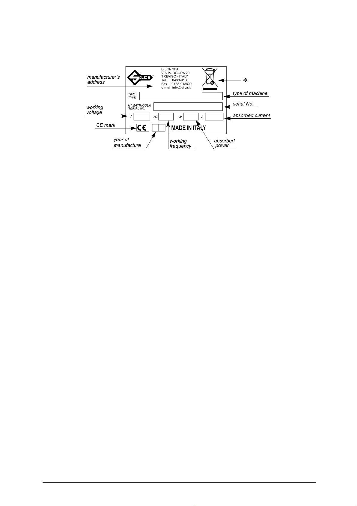
• Machine Identification
The BRAVO MAXIMA key-cutting machine is provided with an identification label which shows the serial
number (fig.2).
Fig. 2
(*) see ch.8 "DISPOSAL", page 34.
Copyright Silca 2011 3
BRAVO MAXIMA II Operating manual - English
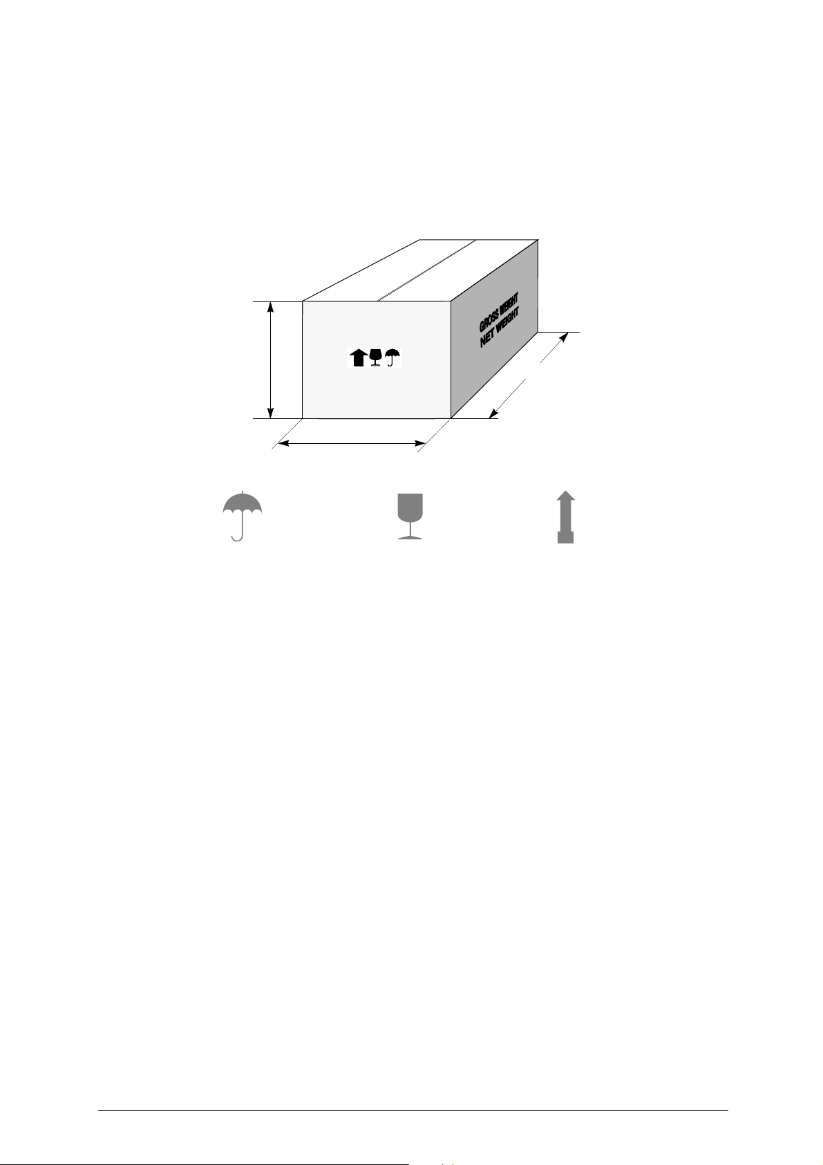
490 mm
590 mm
465 mm
Keep dry This side upHandle with care
1 TRANSPORT
The BRAVO MAXIMA key-cutting machine is easily transported and is not dangerous to handle. The
machine must be placed in its packaging and carried manually by two persons.
1.1 Packing
The BRAVO MAXIMA is packed in a strong cardboard box, the dimensions of which are shown in fig.
3, sufficiently robust to be used for storing the machine for long periods.
Fig. 3
Inside the box the machine is enclosed in two expanded polymer shells. The shells and cardboard box
ensure safe transportation and protect the machine and all its parts.
1.2 Transport
To ensure that the BRAVO MAXIMA key-cuttin g mac hine remai ns inte gral, it mu st always be move d in
its packaging, with the carriage released.
1.3 Unpacking
To remove the machine from the packing box:
1) cut the straps with scissors and remove.
2) prise off the staples;.
3) open the box without damaging it as it may be used again (e.g. removals, dispatch to the
manufacturers for repairs or servicing).
4) check the contents of the box, which should comprise:
5) remove the key-cutting machine from the protective shell.
1BRAVO MAXIMA key-cutting machine packed in a protective shell
1set of documents, including: operating manual, spare parts list and guarantee
1 connecting wire
1 accessory container
4 Copyright Silca 2011
Operating manual - English BRAVO MAXIMA II
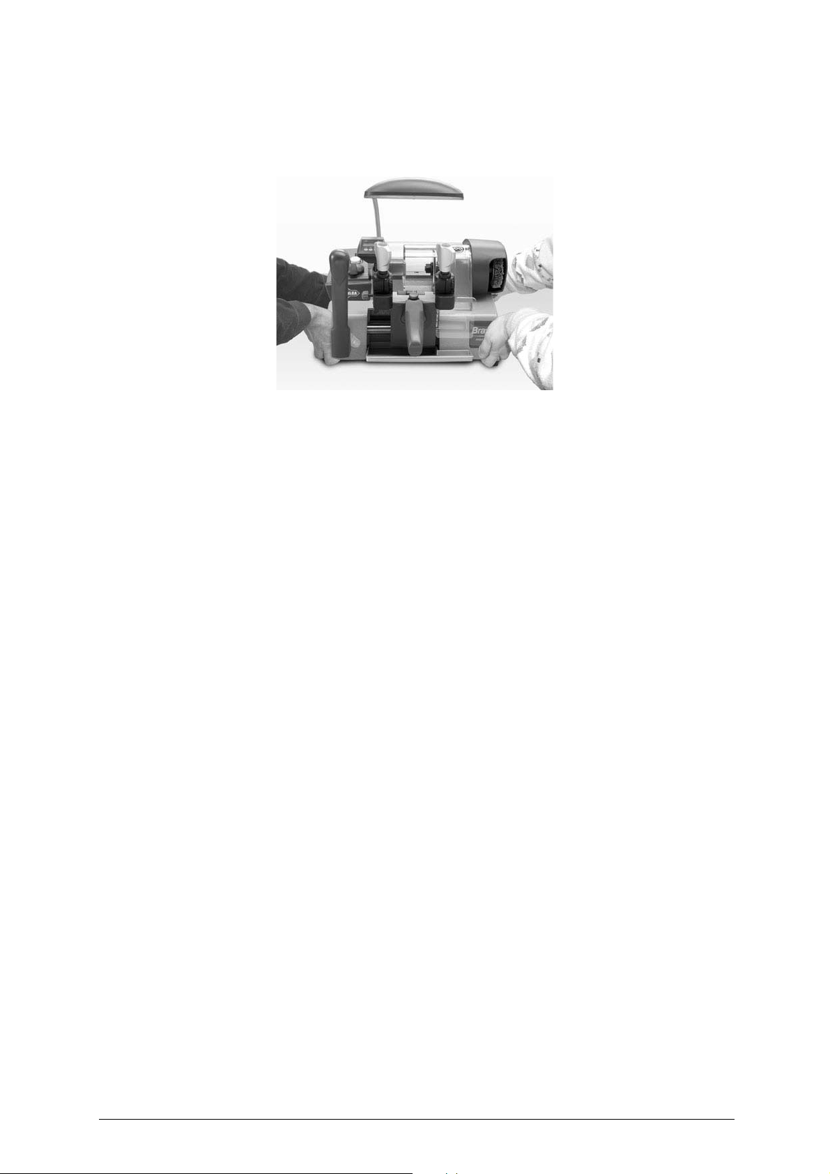
1.4 Handling the machine
When the BRAVO MAXIMA has been unpacked, place it directly on its workbench.
Fig. 4
This operation can be carried out by one or two persons,
to lift and carry the machine
(fig.4).
firmly holding the base and no other part,
Copyright Silca 2011 5

BRAVO MAXIMA II Operating manual - English
U
B1
J
P
O
H
A
I
F
E
Q
D
N V
R
E
K
L
S
T
F
M
B
X
J1
O1
Z
C
2 WORKING PARTS
Fig. 5
A - cutting tool
B - tracer point
B1- tracer point support
C - master switch
D - carriage
E- clamp
F - clamp knob
H - transparent protective shield
I - brush
J - tracer point locking screw
J1- support/tracer point locking screw
K - calibration tabs
L - carriage movement lever
M- brush push button
N - chippings tray
O - tracer point regulating knob
O1- zero registration nut
P - motor start-up commutator
Q - carriage release push button
R - calibration drum
S - neon lamp
T - belt housing
U - double speed motor
V - carriage handle
X - display unit
Z - protection from swarf produced by cutting
6 Copyright Silca 2011

Operating manual - English BRAVO MAXIMA II
3 MACHINE DESCRIPTION
The BRAVO MAXIMA is a professional cutting machine for flat keys used with cylinder locks for doors,
cars and cruciform keys. The main parts of the machine are described below:
• CONTROL PANEL
The control panel with 2 controls is located on the left-hand side of the BRAVO MAXIMA key-cutting
machine: the motor start-up switch (P), which also acts as speed commutator and the push button for
the brush (M) (fig. 5, page 6).
• MOTOR AND TRANSMISSION UNIT
The motor (U) is located on the back of the BRAVO MAXIMA key-cutting machine, under the central
cover.
Motor speed is that more suitable for the materials to be cut. The transmission unit is place d to the right
of the motor.
By means of a belt under a protective cover (T), the transmission unit powe rs the movement of the brush
(I) and cutting tool (A).
• MOBILE UNIT
The mobile unit (D), consisting o f the clamps, is fitt ed to the ho rizontal movement carr iage controll ed by
lever (L) and is provided with a handle (V) on the top of which ca n be found the carria ge release bu tton
(Q).
The carriage movement, along a double shaft on bearing brasses, allows high precision movements
which greatly facilitate all cutting operations.
The carriage is fully protect ed by the ov erhea d cuttin g unit st ructur e which av oids the ac cumula tion of
dust and chippings from the work process.
The BRAVO MAXIMA is completely safe when used properly. However, for greater safety, two safety
devices are provided:
- an automatic braking mechanism for the carriage slide, activated in the key-locking position.
- an automatic carriage releasing device, linked to the return of the gauges to the idle position, which
activates the cutting tool only when the carriage is released.
The key-cutting machine is designed with a sloping protected surface along which swarf is channelled
into the special tray (N), easily removed for emptying and cleaning
• CUTTING UNIT
The cutting unit contains the act ual wor king part s of t he BRAVO MAXIM A key-cu tting machin e, which
operate together to cut and finish keys "read" from the originals. The workin g parts are described below:
Brush
The brush (I) is used to eliminate burrs from the cuts and is made of non-abrasive material.
Cutting Tool
The cutting tool (A) is the part of the BRAVO MAXIMA used for cutting key blanks from the tracer point’s
reading of the cuts on the original key. Th e cutt ing to ol i s in HSS super rapid steel or hard metal and is
covered by a transparent plastic shield (H) which provides protection for the operator.
Tracer point
The tracer point (B) is placed on its own support (B1), to the left of the cutting tool. It has micrometric
regulation which makes it possible to adjust the cutting depth quickly and accurately. The tracer point
comes with an electronic device for zeroing the machine and sho ws the regulation values on the display.
The tracer point regulatin g knob (O) and t he nut (O1) for regist ering zero are inclu ded in the unit . The
original key-reading unit is compl ete with th e tracer po int locking screw (J) and the screw whi ch holds i t
to the support (J1).
Clamps
The clamps of BRAVO MAXIMA key-cutting machine ensure perfect grip on keys (fig. 6, page 8).
The clamps are placed in front of the tracer point and cutti ng tool (E) respectively to grip the o riginal key
and the key blank. With the clamps, cutting is rapid and precise for various types of keys and a wire
range of optional accessories can be used on the machine.
Anatomical knobs (F) with which to secure the keys are fitted on top of the clamps. The knobs are
designed so that only slight pressure is needed to give perfect grip on the keys.
On the lower side of the clamps are the calibration tabs (K). The rotating drum for the gauges (R) is
placed at the centre of the carriage, between the two clamps.
Illumination of the work area
In order to facilitate safe use of the BRAVO MAXIMA key-cutting machine, it has a fixe d neon la mp (S)
that illuminates the work area and is switched on by means of the master switch (C).
Copyright Silca 2011 7
BRAVO MAXIMA II Operating manual - English
Fig. 6
3.1 Safety
• Cutter motor protection
ATTENTION: the cutter motor is protected from overheating by a device (inside the motor) that stop s it when
it reaches a dangerous temperature .
This condition can occur when the machine motor is left on continuously, with high ambient
temperatures or in severe working conditions. If the cutter motor overheats it cuts out
automatically. In such cases proceed as follows:
a) turn off the master switch (C).
b) let the motor cool for at least 2 hours then use the machine normally.
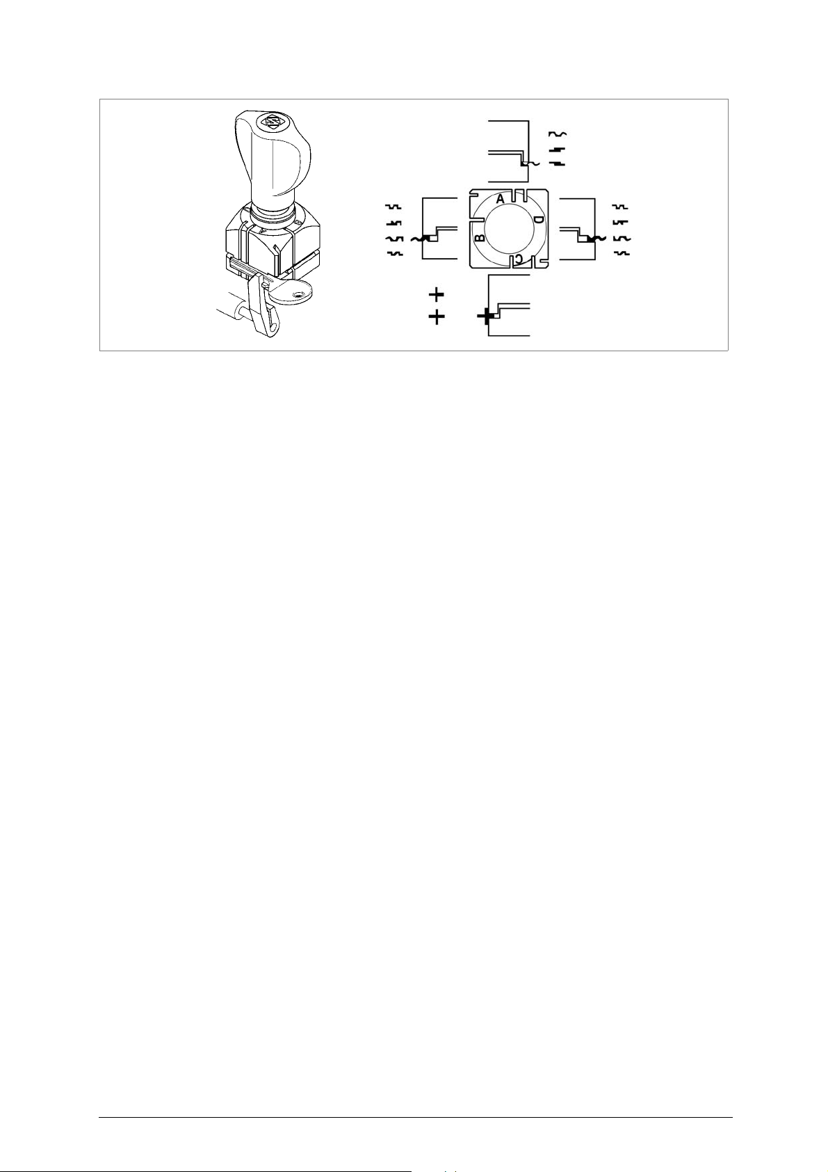
• Start-up
The master switch (C) has a safety function that prevents untimely start-up when voltage returns after
a cut-out.
3.2
Technical Data
ELECTRICAL
PROPERTIES:
MOTOR: 2 speed single phase asynchronous 230V-50Hz (other voltages on request)
CUTTING TOOL: Super Rapid Steel (8% Co) / Carbide cutter (only on W-Max version)
MOVEMENTS: on permanently lubricated bearings and sintered, self-cleaning, self-
CLAMP: high precision, with four sides
SAFETY DEVICES: motor start-up by means of carriage pick-up with gauges in the idle position
MAXIMUM
LENGTH OF CUTS: 42 mm
ILLUMINATION: neon lamp
DIMENSIONS: width: 400 mm depth: 520 mm height: 400 mm
NOISE POTENTIAL: Lw (A) = 90 dB (A) - speed 1 (steel keys)
230V - 50Hz - 300W - 1,8A
lubricating bushings
Lw (A) = 89,5 dB (A) - speed 2 (brass keys)
WEIGHT: 22,5 Kg.
8 Copyright Silca 2011

Operating manual - English BRAVO MAXIMA II
3
M
black
black
brown
4
light blue
brown
brown
(
light blue
0
black
blue
2
12
1
W
V
U32 1
brown
brown
light blue
light blue
brown
)
yellow/green
brown brown
light blue
light blue
(
)
light blue
light blue
1
2
3
7
8
9
10
6
5
4
11 12
13
14
3.3
Electric circuit
The BRAVO MAXIMA key-cutting machine has a 2 speed single phase motor, 230V- 50Hz.
The main parts of the electric circuit on the BRAVO MAXIMA are listed below:
1) Main plug with fuses
2) Safe main switch
3) Brush push button
4) Commutator
5) Carriage microswitch
6) Cutter motor condenser
7) Lamp reactor
8) Terminal board
9) Neon lamp
10)Motor
Fig. 7
11)Display
12)Lithium battery CR2032
13)Potentiometer
14)Tracer Point
Copyright Silca 2011 9
 Loading...