

Page 1

Operating manual
D432446XA
vers.5.0
EN
®
Page 2

© 2011 SILCA S.p.A - Vittorio Veneto
This manual has been drawn up by SILCA S.p.A.
All rights reserved. No part of this publication may be reproduced or used in any form or by any means (photocopying,
microfilm or other) without the written permission of SILCA S.p.A.
Edition:
Printed in Vittorio Veneto
by SILCA S.p.A.
via Podgora, 20 (Z.I.)
31029 VITTORIO VENETO (TV) - Italy
April 2011
Page 3

INDEX
GUIDE TO THE MANUAL ......................................................................................1
GENERAL INTRODUCTION .................................................................................2
1 TRANSPORT ...................................................................................................4
1.1 Packing .................................................................................................4
1.2 Transport ..............................................................................................4
1.3 Unpacking .............................................................................................4
1.4 Handling the machine .............................................................. .............5
2 WORKING PARTS ..........................................................................................6
3 MACHINE DESCRIPTION ...............................................................................7
3.1 Safety ....................................................................................................8
3.2 Technical Data ......................................................................................8
3.3 Electric circuit .................................... ... .................................................9
4 ACCESSORIES PROVIDED .................................. ..................................... ..10
5 MACHINE INSTALLATION AND PREPARATION .......................................11
5.1 Checking for damage ..........................................................................11
5.2 Environmental conditions ....................................................................11
5.3 Positioning ..........................................................................................11
5.4 Description of work station ..................................................................12
5.5 Graphics .............................................................................................12
5.6 Separate parts ............................................. ... ....................................12
5.7 Connection to the mains .....................................................................12
5.8 Display functions ............................................. ....................................13
5.9 Checking and setting ..........................................................................14
5.10 Calibration ...........................................................................................14
5.11 Gauging by electric contact ................................................................14
5.12 Mechanical calibration (without electric contact) ................................16
6 CUTTING OPERATIONS ..............................................................................18
6.1 Key cutting ..........................................................................................18
6.2 Cutting cruciform keys (with 3 fins) .....................................................19
7 CLEANING AND MAINTENANCE ................................................................21
7.1 Preparing for maintenance .................................................................21
7.2 Replacing the cutting tool ...................................................................21
7.3 Replacing the brush ................................................................. ... ... .....22
7.4 Replacing the tracer point ....................................... ... .........................22
7.5 Regulating of maximum carriage depth ..............................................23
7.6 Replacing the fuses ................................................ ... ... ......................23
7.7 Access to bottom compartment ..........................................................24
7.8 Replacing the master switch ...............................................................24
7.9 Replacing the condenser (motor) and/or feeder (lamp) ......................25
7.10 Replacing the microswitch ............................................................. ... ..26
7.11 Replacing the commutator ..................................................................27
7.12 Replacing the push button ..................................................................28
7.13 Replacing and/or tightening the belt ...................................................29
7.14 Replacing the 2 speed motor ..............................................................30
7.15 Replacing the light bulb .......................................... ... .........................31
7.16 Replacing carriage spring ...................................................................31
7.17 Replacing the Display Unit ..................................................................33
7.18 Replacing the Display Battery .............................................................33
8
DISPOSAL ....................................................................................................34
9 ASSISTANCE ................................................................................................35
9.1 How to request service .......................................................................35
Page 4

Page 5

Operating manual - English BRAVO MAXIMA II
2
1
5
7
3
6
4
1
3
5
7
2
1
8
5
3
GUIDE TO THE MANUAL
This manual is a guide to the use of BRAVO MAXIMA key-cutting machine
Read it carefully; it is essential if you wish to operate your machine safely and efficiently.
C
ONSULTATION
The contents of the manual are divided into sections relating to:
- Transport and handling ............................................................................................... Ch. 1
- Description of machine and safety devices ................................................................ Ch. 2-3-4
- Proper use of machine ............................................................................................... Ch. 5-6
- Cleaning and Maintenance ......................................................................................... Ch. 7
T
ECHNICAL TERMS
Common technical terms are used in this manual. To assist those with little experience of key cutting,
below is an illustration of the terms used for the different parts of keys.
.
Fig. 1
1) Head
2) Rim
3) Stop
4) Stem
5) Tip
6) Back
7) Cuts
8) Stem
Copyright Silca 2011 1
Page 6

BRAVO MAXIMA II Operating manual - English
GENERAL INTRODUCTION
The BRAVO MAXIMA key-cutting machine has been designed according to the specifications of the
Machine Directives. From the design stage risks for the operator have been eliminated in all areas:
transport, key-cutting, regulation and maintenance.
Other risks have been eliminated by the use of protective devices for the operator.
The protective devices used are designed not to provoke further risks and, above all, they cannot be
ignored unless deliberately cut out. They do not hinder visibility of the work area.
A special adhesive label is attached to the machine warning the operator to use goggles during the
cutting operations, and this is strongly recommended in this manual.
The material used in the manufacture of this machine and the components employed during use of the
machine are not dangerous and their use complies with standards.
U
SE
The BRAVO MAXIMA must be installed and used in the way laid down by the manufacturer.
If the key-cutting machine is used differently or for purposes different from those described in this
manual, the customer will forego any rights he may have over SILCA S.p.A. Furthermore, unforeseen
danger to the operator or any third parties may arise from incorrect use of the machine.
Negligence in the use of the machine or failure on the part of the operator to observe the instructions
given in this manual are not covered by the guarantee and the manufacturer declines all responsibility
in such cases.
It is therefore indispensable to read the operating manual c arefully in order to make the best use
of the BRAVO MAXIMA and benefit from its potential.
Instructions manual
The instructions manual provided with the machine is essential to its proper use and to carry out the
necessary maintenance.
We therefore recommend protecting the man ual from d amag e in a sa fe she ltered place, ea sily to h and
for quick consultation.
F
URTHER RISKS
There are no further risks arising from the use of the machine.
P
ROTECTION AND SAFETY PRECAUTIONS FOR THE OPERATOR
The BRAVO MAXIMA key-cutting machine is built entire ly to standards. The o perations for which it has
been designed are easily carried out at no risk to the operator.
The adoption of general safety precautions (wearing protective goggles) and observation of the
instructions provided by the manufacturer in this manual eliminate all human error, unless deliberate.
The BRAVO MAXIMA key-cutting machine is designed with features which make it completely safe in
all its parts.
• Power supply
The key-cutting machine is powered by electricity supplied through a separable earthed plug.
• Start-up
The machine is turned on by means of the master switch located on the right-h and side. The switch has
a safety function that prevents untimely start-up when voltage returns after a cut-out.
•Operation
The speed commutator activates the machine and allows selection of the required speed.
• Illumination
The work area is illuminated by a neon lamp operated by means of the master switch.
• Maintenance
The operations to regulate, service, repair and clean the machine have been devised in the simplest
and safest way possible. There is no danger of removable parts being re-placed wrongly or unsafely.
2 Copyright Silca 2011
Page 7
Operating manual - English BRAVO MAXIMA II
• Machine Identification
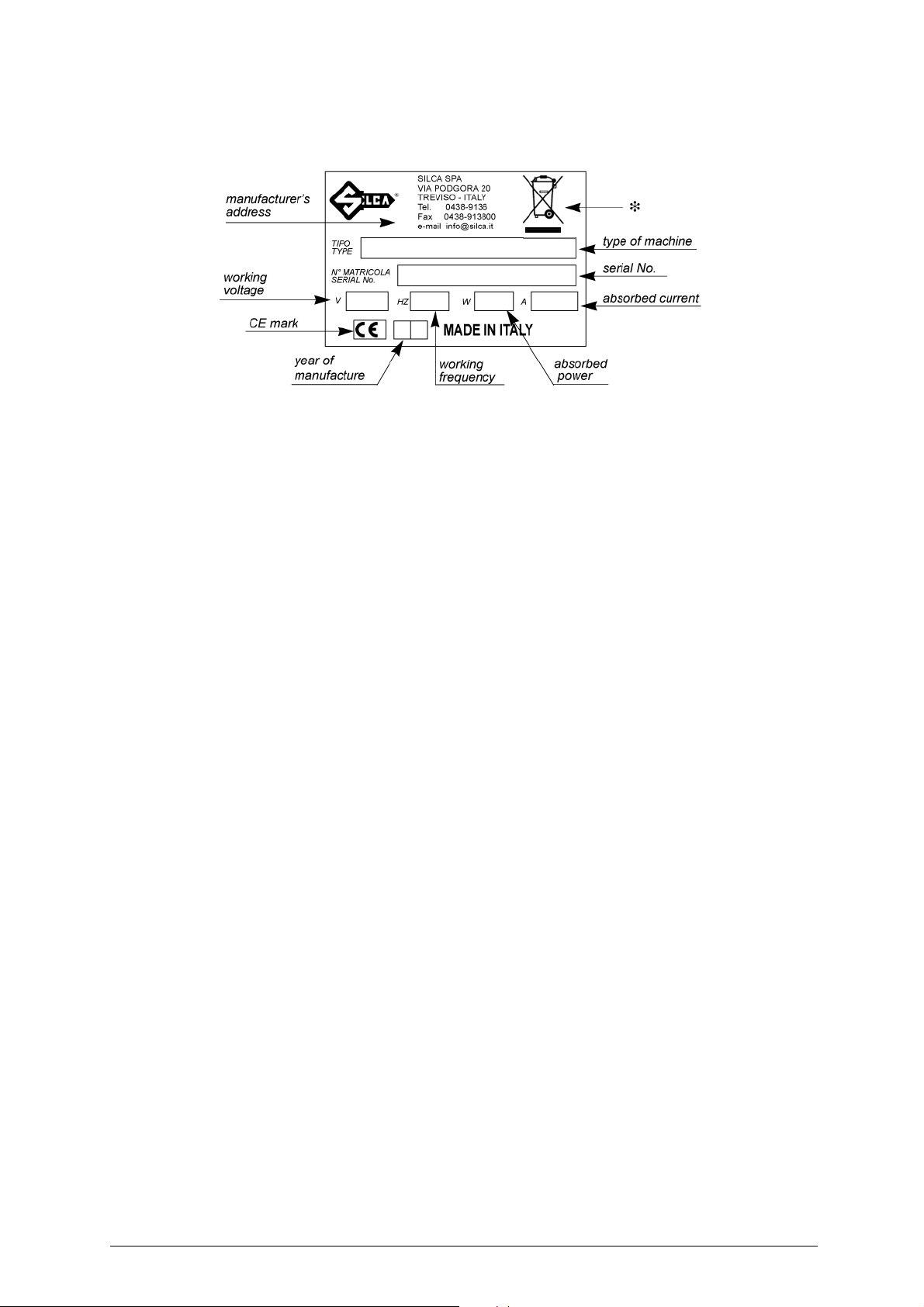
The BRAVO MAXIMA key-cutting machine is provided with an identification label which shows the serial
number (fig.2).
Fig. 2
(*) see ch.8 "DISPOSAL", page 34.
Copyright Silca 2011 3
Page 8
BRAVO MAXIMA II Operating manual - English
490 mm
590 mm
465 mm
Keep dry This side upHandle with care
1 TRANSPORT
The BRAVO MAXIMA key-cutting machine is easily transported and is not dangerous to handle. The
machine must be placed in its packaging and carried manually by two persons.
1.1 Packing
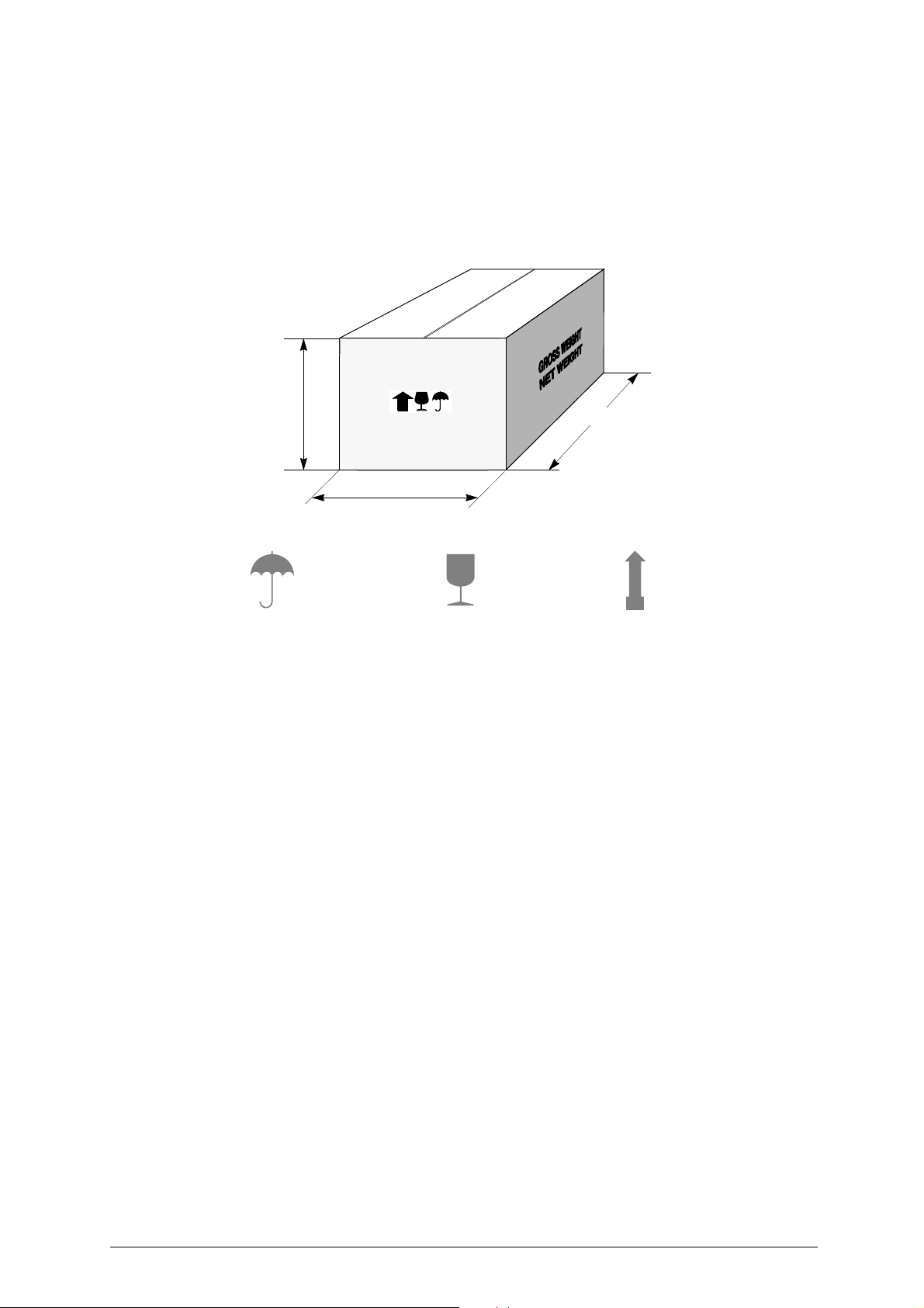
The BRAVO MAXIMA is packed in a strong cardboard box, the dimensions of which are shown in fig.
3, sufficiently robust to be used for storing the machine for long periods.
Fig. 3
Inside the box the machine is enclosed in two expanded polymer shells. The shells and cardboard box
ensure safe transportation and protect the machine and all its parts.
1.2 Transport
To ensure that the BRAVO MAXIMA key-cuttin g mac hine remai ns inte gral, it mu st always be move d in
its packaging, with the carriage released.
1.3 Unpacking
To remove the machine from the packing box:
1) cut the straps with scissors and remove.
2) prise off the staples;.
3) open the box without damaging it as it may be used again (e.g. removals, dispatch to the
manufacturers for repairs or servicing).
4) check the contents of the box, which should comprise:
5) remove the key-cutting machine from the protective shell.
1BRAVO MAXIMA key-cutting machine packed in a protective shell
1set of documents, including: operating manual, spare parts list and guarantee
1 connecting wire
1 accessory container
4 Copyright Silca 2011
Page 9
Operating manual - English BRAVO MAXIMA II
1.4 Handling the machine
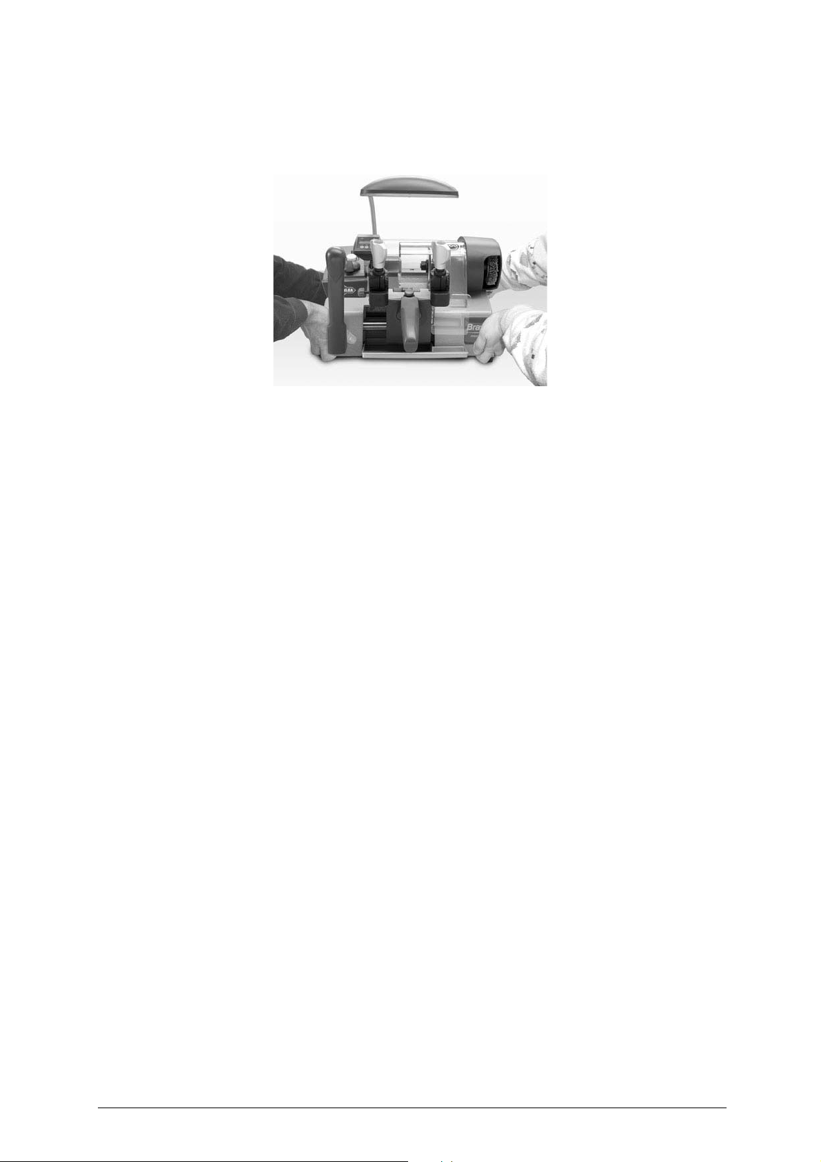
When the BRAVO MAXIMA has been unpacked, place it directly on its workbench.
Fig. 4
This operation can be carried out by one or two persons,
to lift and carry the machine
(fig.4).
firmly holding the base and no other part,
Copyright Silca 2011 5
Page 10

BRAVO MAXIMA II Operating manual - English
U
B1
J
P
O
H
A
I
F
E
Q
D
N V
R
E
K
L
S
T
F
M
B
X
J1
O1
Z
C
2 WORKING PARTS
Fig. 5
A - cutting tool
B - tracer point
B1- tracer point support
C - master switch
D - carriage
E- clamp
F - clamp knob
H - transparent protective shield
I - brush
J - tracer point locking screw
J1- support/tracer point locking screw
K - calibration tabs
L - carriage movement lever
M- brush push button
N - chippings tray
O - tracer point regulating knob
O1- zero registration nut
P - motor start-up commutator
Q - carriage release push button
R - calibration drum
S - neon lamp
T - belt housing
U - double speed motor
V - carriage handle
X - display unit
Z - protection from swarf produced by cutting
6 Copyright Silca 2011
Page 11

Operating manual - English BRAVO MAXIMA II
3 MACHINE DESCRIPTION
The BRAVO MAXIMA is a professional cutting machine for flat keys used with cylinder locks for doors,
cars and cruciform keys. The main parts of the machine are described below:
• CONTROL PANEL
The control panel with 2 controls is located on the left-hand side of the BRAVO MAXIMA key-cutting
machine: the motor start-up switch (P), which also acts as speed commutator and the push button for
the brush (M) (fig. 5, page 6).
• MOTOR AND TRANSMISSION UNIT
The motor (U) is located on the back of the BRAVO MAXIMA key-cutting machine, under the central
cover.
Motor speed is that more suitable for the materials to be cut. The transmission unit is place d to the right
of the motor.
By means of a belt under a protective cover (T), the transmission unit powe rs the movement of the brush
(I) and cutting tool (A).
• MOBILE UNIT
The mobile unit (D), consisting o f the clamps, is fitt ed to the ho rizontal movement carr iage controll ed by
lever (L) and is provided with a handle (V) on the top of which ca n be found the carria ge release bu tton
(Q).
The carriage movement, along a double shaft on bearing brasses, allows high precision movements
which greatly facilitate all cutting operations.
The carriage is fully protect ed by the ov erhea d cuttin g unit st ructur e which av oids the ac cumula tion of
dust and chippings from the work process.
The BRAVO MAXIMA is completely safe when used properly. However, for greater safety, two safety
devices are provided:
- an automatic braking mechanism for the carriage slide, activated in the key-locking position.
- an automatic carriage releasing device, linked to the return of the gauges to the idle position, which
activates the cutting tool only when the carriage is released.
The key-cutting machine is designed with a sloping protected surface along which swarf is channelled
into the special tray (N), easily removed for emptying and cleaning
• CUTTING UNIT
The cutting unit contains the act ual wor king part s of t he BRAVO MAXIM A key-cu tting machin e, which
operate together to cut and finish keys "read" from the originals. The workin g parts are described below:
Brush
The brush (I) is used to eliminate burrs from the cuts and is made of non-abrasive material.
Cutting Tool
The cutting tool (A) is the part of the BRAVO MAXIMA used for cutting key blanks from the tracer point’s
reading of the cuts on the original key. Th e cutt ing to ol i s in HSS super rapid steel or hard metal and is
covered by a transparent plastic shield (H) which provides protection for the operator.
Tracer point
The tracer point (B) is placed on its own support (B1), to the left of the cutting tool. It has micrometric
regulation which makes it possible to adjust the cutting depth quickly and accurately. The tracer point
comes with an electronic device for zeroing the machine and sho ws the regulation values on the display.
The tracer point regulatin g knob (O) and t he nut (O1) for regist ering zero are inclu ded in the unit . The
original key-reading unit is compl ete with th e tracer po int locking screw (J) and the screw whi ch holds i t
to the support (J1).
Clamps
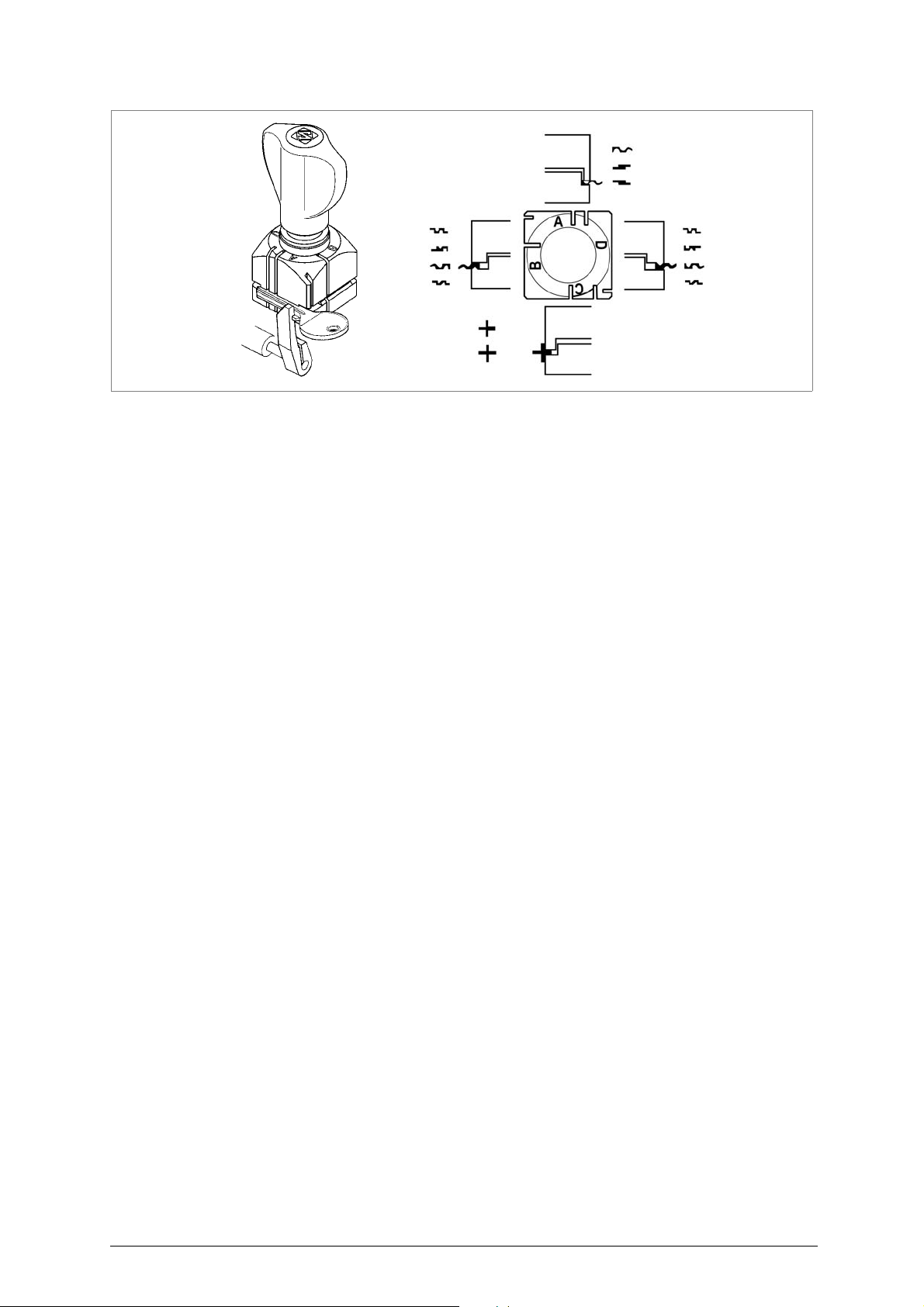
The clamps of BRAVO MAXIMA key-cutting machine ensure perfect grip on keys (fig. 6, page 8).
The clamps are placed in front of the tracer point and cutti ng tool (E) respectively to grip the o riginal key
and the key blank. With the clamps, cutting is rapid and precise for various types of keys and a wire
range of optional accessories can be used on the machine.
Anatomical knobs (F) with which to secure the keys are fitted on top of the clamps. The knobs are
designed so that only slight pressure is needed to give perfect grip on the keys.
On the lower side of the clamps are the calibration tabs (K). The rotating drum for the gauges (R) is
placed at the centre of the carriage, between the two clamps.
Illumination of the work area
In order to facilitate safe use of the BRAVO MAXIMA key-cutting machine, it has a fixe d neon la mp (S)
that illuminates the work area and is switched on by means of the master switch (C).
Copyright Silca 2011 7
Page 12
BRAVO MAXIMA II Operating manual - English
Fig. 6
3.1 Safety
• Cutter motor protection
ATTENTION: the cutter motor is protected from overheating by a device (inside the motor) that stop s it when
it reaches a dangerous temperature .
This condition can occur when the machine motor is left on continuously, with high ambient
temperatures or in severe working conditions. If the cutter motor overheats it cuts out
automatically. In such cases proceed as follows:
a) turn off the master switch (C).
b) let the motor cool for at least 2 hours then use the machine normally.
• Start-up
The master switch (C) has a safety function that prevents untimely start-up when voltage returns after
a cut-out.
3.2
Technical Data
ELECTRICAL
PROPERTIES:
MOTOR: 2 speed single phase asynchronous 230V-50Hz (other voltages on request)
CUTTING TOOL: Super Rapid Steel (8% Co) / Carbide cutter (only on W-Max version)
MOVEMENTS: on permanently lubricated bearings and sintered, self-cleaning, self-
CLAMP: high precision, with four sides
SAFETY DEVICES: motor start-up by means of carriage pick-up with gauges in the idle position
MAXIMUM
LENGTH OF CUTS: 42 mm
ILLUMINATION: neon lamp
DIMENSIONS: width: 400 mm depth: 520 mm height: 400 mm
NOISE POTENTIAL: Lw (A) = 90 dB (A) - speed 1 (steel keys)
230V - 50Hz - 300W - 1,8A
lubricating bushings
Lw (A) = 89,5 dB (A) - speed 2 (brass keys)
WEIGHT: 22,5 Kg.
8 Copyright Silca 2011
Page 13

Operating manual - English BRAVO MAXIMA II
3
M
black
black
brown
4
light blue
brown
brown
(
light blue
0
black
blue
2
12
1
W
V
U32 1
brown
brown
light blue
light blue
brown
)
yellow/green
brown brown
light blue
light blue
(
)
light blue
light blue
1
2
3
7
8
9
10
6
5
4
11 12
13
14
3.3
Electric circuit
The BRAVO MAXIMA key-cutting machine has a 2 speed single phase motor, 230V- 50Hz.
The main parts of the electric circuit on the BRAVO MAXIMA are listed below:
1) Main plug with fuses
2) Safe main switch
3) Brush push button
4) Commutator
5) Carriage microswitch
6) Cutter motor condenser
7) Lamp reactor
8) Terminal board
9) Neon lamp
10)Motor
Fig. 7
11)Display
12)Lithium battery CR2032
13)Potentiometer
14)Tracer Point
Copyright Silca 2011 9
Page 14
BRAVO MAXIMA II Operating manual - English
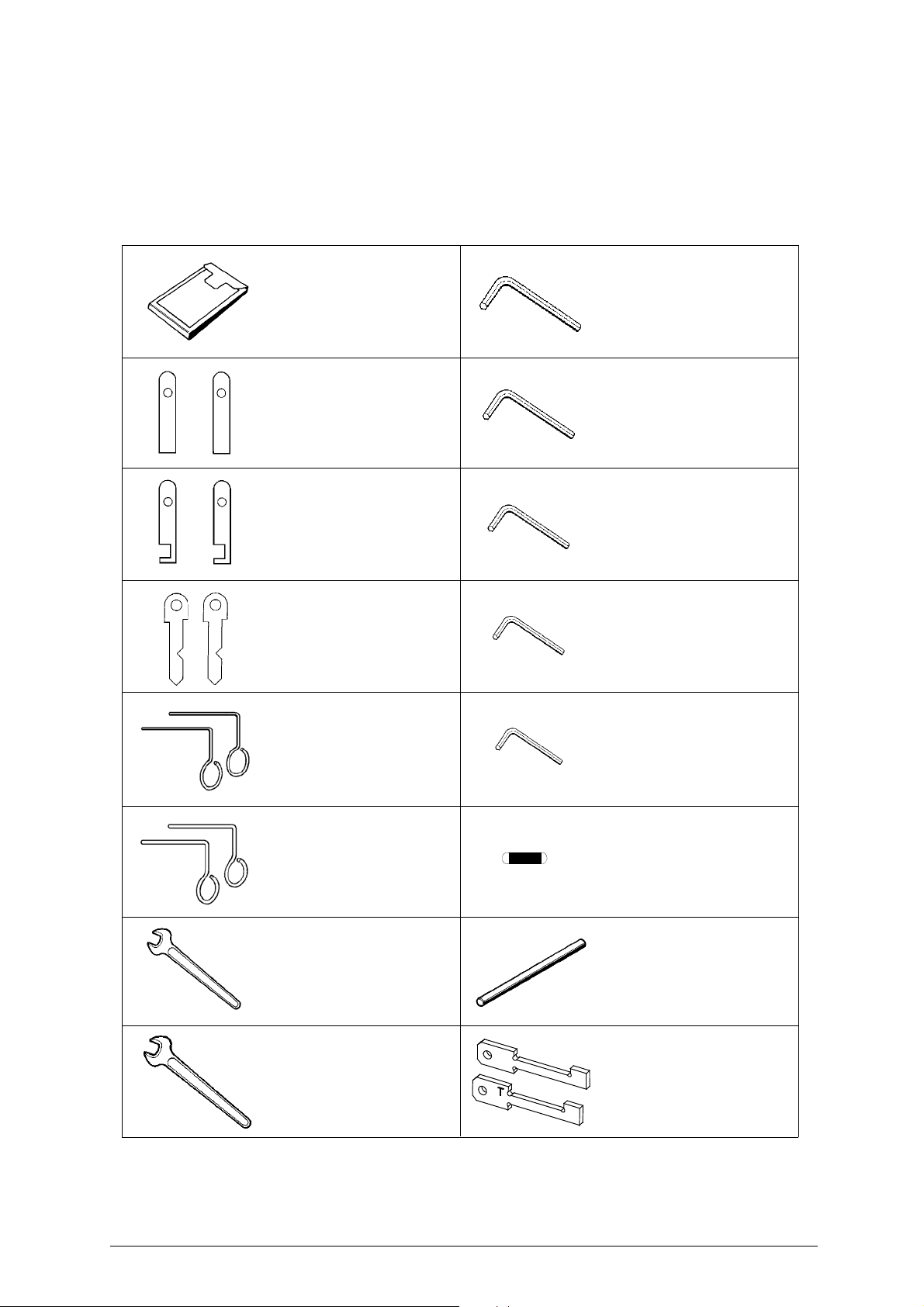
STEEL PIN ø 1.20 mm
2 pcs.
CUTTER LOCKING PIN
1 pcs.
19 mm SPANNER
1 pcs.
STEEL BAR
2 pcs.
STEEL BAR WITH NECK
2 pcs.
ADJUSTING BAR
2 pcs.
STEEL PIN ø 1.70 mm
2 pcs.
FUSE
5 Amps rapid on 230V
(5 pcs.)
POUCH
1 pcs.
ALLEN WRENCH 2 mm
1 pcs.
ALLEN WRENCH 2,5 mm
1 pcs.
ALLEN WRENCH 3 mm
1 pcs.
ALLEN WRENCH 4 mm
1 pcs.
ALLEN WRENCH 5 mm
1 pcs.
10 mm SPANNER
1 pcs.
D927403ZR
Electric Contact Template
CUTTER SIDE (C)
D927927ZR
Electric Contact Template
TRACER POINT SIDE (T)
C
4 ACCESSORIES PROVIDED
To ensure trouble-free working with the BRAVO MAXIMA, it is advisable to always have certain spare
parts on hand. It is good policy to have a replacement CUTTER, BRUSH and BELT in the tool box.
BRAVO MAXIMA is supplied with a full range of accessories.
The accessories provided by Silca are all that is necessary to carry out the operations for which the
machine is designed.
10 Copyright Silca 2011
Page 15
Operating manual - English BRAVO MAXIMA II
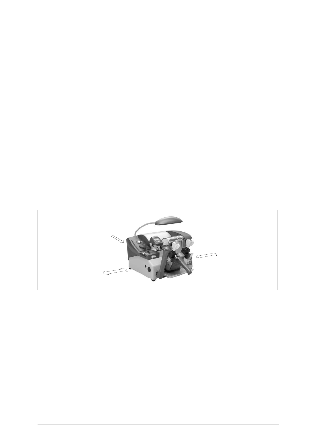
200 mm
200 mm
200 mm
5 MACHINE INSTALLATION AND PREPARATION
The BRAVO MAXIMA key-cutting machine can be in st alled by the purchaser and does not require any
special skills.
The machine is supplied ready for use and does not need to be set up. However, some checks and
preparation for use need to be carried out by the operator.
5.1 Checking for damage
The BRAVO MAXIMA key-cutting machine is solid and compact and will not normally damage if
transport, unpacking and installation have all been carried out according to the instructions in this
manual.
However, it is always advisable to check that the machine has not suffered any damage.
5.2 Environmental conditions
To ensure that the best use is made of the BRAVO MAXIMA key-cutting machine, certain parameters
must be borne in mind:
- damp, badly ventilated sites should be avoided.
- the ideal conditions for the machine are:
temperature: between 10 and 40 °C
relative humidity: approx. 60%
5.3 Positioning
Place the key-cutting machine on a horizontal surface, solid enough to take the weight.
To facilitate operation and maintenance, install the machine with a clearance of at least 200 mm on all
sides (fig.8).
Ensure that the machine stands perfectly balanced on the four feet. Vibration is avoided when the
machine is properly set on the horizontal plane.
ATTENTION: ensure that the machine voltage is the same as that of the mains, which must be properly
earthed and provided with a differential switch.
Fig. 8
Copyright Silca 2011 11
Page 16
BRAVO MAXIMA II Operating manual - English
L
P
M
V
C
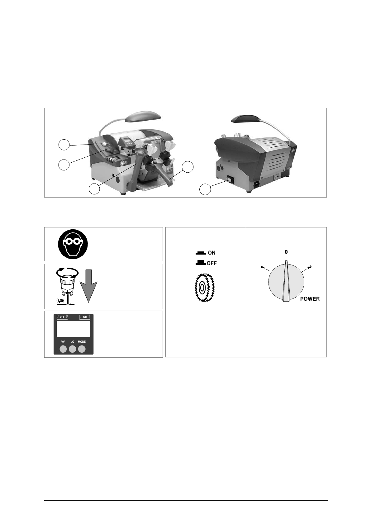
THE USE OF
PROTECTIVE GOGGLES
IS COMPULSORY
BRUSH PUSH BUTTON
MOTOR START-UP
COMMUTATOR
2 SPEED
(OFF)
(speed 1) (speed 2)
TRACER POINT
WITH MICROMETRIC
REGULATION
DISPLAY
(see ch. 5.8)
5.4 Description of work station
The key-cutting machine needs only one operator, who has the following controls at his/her disposal:
• master switch (C)
• commutator (P)
• push button (M) to activate the brush
• carriage movement lever (L), placed at the bottom left-hand side
• carriage handle (V)
Fig. 9
5.5 Graphics
5.6 Separate parts
The separately packed parts must be installed on the BRAVO MAXIMA key-cutting machine by the
purchaser, as follows:
Connection wire
Connect the supply wire to the inlet on the back of the machine.
5.7 Connection to the mains
For the safety of the operator and the machine it is important to ensure that the machine is connected
to the proper mains voltage by means of an earthed differential switch.
12 Copyright Silca 2011
Page 17
Operating manual - English BRAVO MAXIMA II
.00
- .10
.10
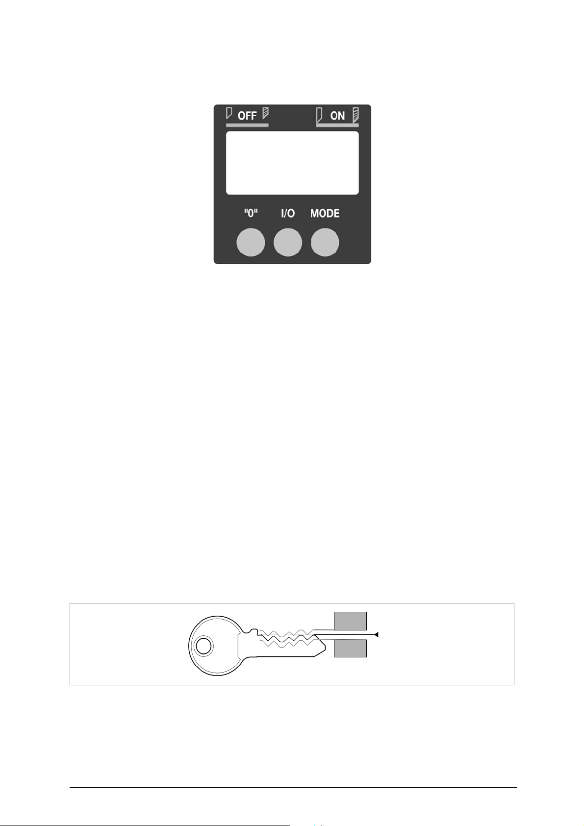
5.8 Display functions
Fig. 10
I/O key
: press for about 1 second to power the display (if off) or turn it off (if on).
0 key
: press for about 1 second to zero the tracer point position. E.g. if the machine
has already been gauged, but the cutting depth requires alteration (increasing
or decreasing values), loosen the screw (J) and adjust the ring nut (O) The
display will show the value (positive or negative), expressed in hundredths of
a millimetre (or thousandths of an inch) (fig.11); a mm scale goes to +/- .99
then passes to 1.00, when the value on the display will flash. The value can
no longer be altered because such a big adjustment is not allowed.
MODE key
MODE key+ 0 key
BATTERY SYMBOL
OFF
: activates the "
When this key is pressed (with display on) one of the following phrases
appears:
-
OFF
indicates no electrical contact.
-
ON
indicates electrical contact.
: press simultaneously for about 3 seconds (display on) to change the
measurement scale (mm or inches), which will go from .00 (for mm scale) to
.000 (for inch scale) or vice versa, according to the conditions on the display.
: when this appears on the display, it indicates that the display unit battery is
down and must be replaced (ch.7.18, page 33).
: automatically switches off the display about 3 minutes after switching on or
from the last movement shown.
(Restart electrical contact by pressing the I/O key).
Electric contact
" (ch.5.11 Gauging by electric contact).
Fig. 11
Copyright Silca 2011 13
Page 18
BRAVO MAXIMA II Operating manual - English
6
4
8
9
0
cutting
I II III IV V VI
cutting
space
depth
R
Q
K
V
K
TEMPLATE (C)TEMPLATE (T)
TRACER POINT SIDE CUTTER SIDE
5.9 Checking and setting
The cutting tool on the BRAVO MAXIMA is the part used to cut the key blanks and should be periodically
checked and replaced, if necessary.
Every time the cutting tool is changed, and during periodical operational tests, check calibration.
5.10 Calibration
Calibration should be carried out whenever parameters must be set on the machine.
BRAVO MAXIMA requires two types of calibration:
Fig. 12
depth
and
axis
.
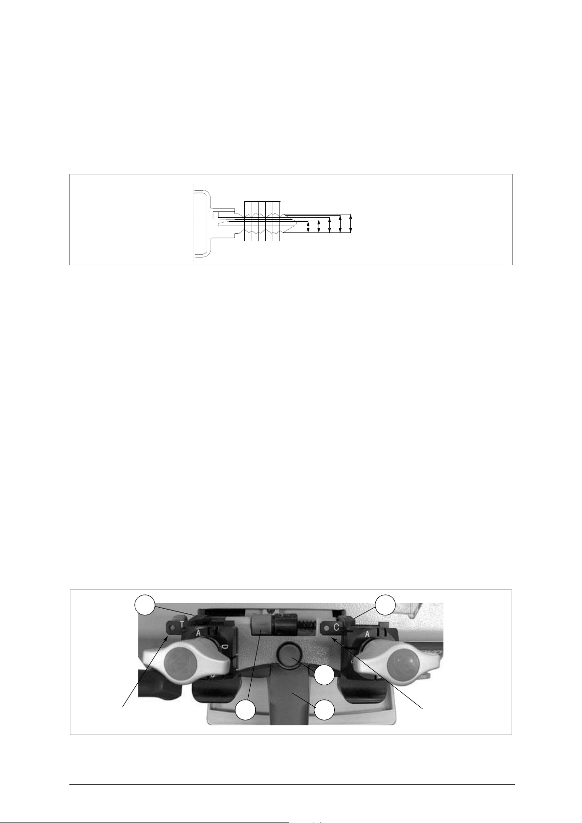
5.11 Gauging by electric contact
D
EPTH CALIBRATION
Depth calibration is regulation of the cutting depth (fig.12). Proceed as follows:
1) Turn off the master switch (C) to operate safely and prevent activation of the cutting tool.
2) Position the electric contact templates on the clamps and proceed as follows:
a) ensure that the keys adhere to the clamps and that the callipers (K) are in full contact with the
stops.
b) to take the callipers into contact with the keys, rotate the drum (R) towards you (away from
you to return to the ideal position).
c) Press the I/O key on the display in order to turn it on.
d) Press the MODE key; the display will show the word OFF (no contact).
ATTENTION: the carriage will be released only if the callipers are in the ideal position.
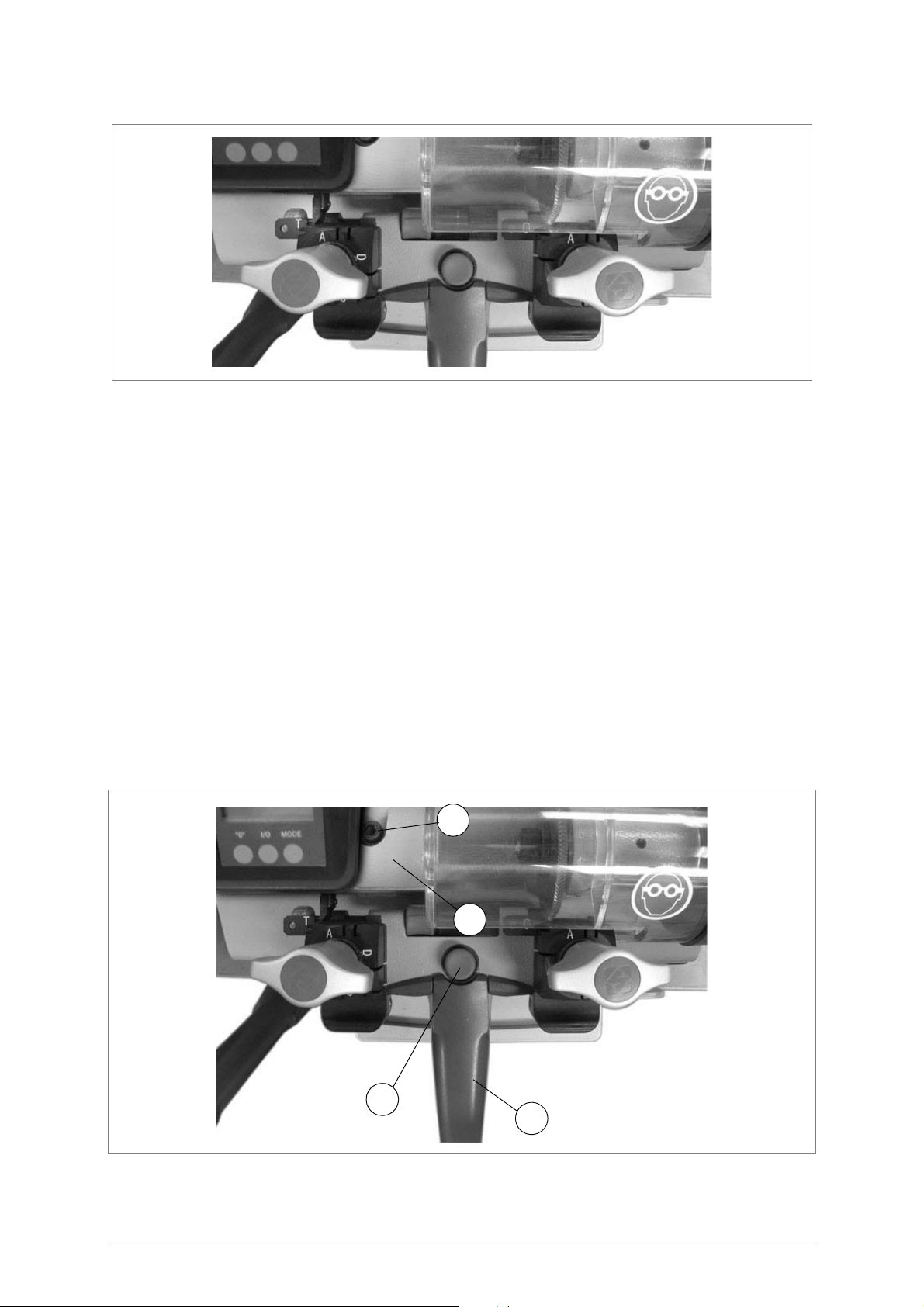
3) Release the carriage by lowering the knob (V) and pressing the push button (Q) right down (fig.13).
4) Raise the carriage and take up to the cutting tool.
5) Take the templates in contact with cutter and tracer point (fig. 14, page 15).
6) The display should show the word ON; if not, proceed as follows:
a) loosen the screw (J2) locking the tracer point (fig.18, pag.17).
b) turn the knob (O) clockwise to move the tracer point forwards.
c) turn the knob (O) anticlockwise to move the tracer point backwards.
7) Lock screw (J2) when ON appears.
8) Zero the tracer point by taking the reference index on the handwheel (O1) to the white mark on the
graduated drum, as described below:
a) with one hand hold still the knurled part of the knob (O).
b) with the other hand turn the mobile part below it (O1).
:
Fig. 13
14 Copyright Silca 2011
Page 19
Operating manual - English BRAVO MAXIMA II
J1
B1
Q
V
Fig. 14
A
XIS CALIBRATION
Axis calibration is regulation of the cutting space on the key (fig. 12, page 14); proceed as follows:
1) Turn off the master switch (C) to operate safely and prevent activation of the cutting tool.
2) Position the electric contact templates on the clamps (fig. 13, page 14) and proceed as follows:
a) ensure that the keys adhere to the clamps and that the callipers (K) are in full contact with the
stops.
b) to take the callipers into contact with the keys, rotate the drum (R) towards you (away from
you to return to the ideal position).
c) Press the I/O key on the display in order to turn it on.
d) Press the MODE key; the display will show the word OFF (no contact).
ATTENTION: the carriage will be released only if the callipers are in the ideal position.
3) Release the carriage by lowering the knob (V) and pressing the push button (Q) right down (fig.15).
4) Take the right-hand side of the templates in contact with the cutter and tracer point.
5) The display should show the word ON; if not, proceed as follows:
a) loosen the screw (J1) to move the tracer point (fig.15).
b) move the tracer point support (B1) sideways by loosening or tightening the screw (B2)
(fig.18, pag.17) until ON appears.
c) tighten the screw (J1) all the way, without exerting pressure.
6)
Lower the carriage by means of the handle (V) (it will engage automatically
7) Remove the templates.
:
).
Fig. 15
Copyright Silca 2011 15
Page 20
BRAVO MAXIMA II Operating manual - English
K
K
R
Q
V
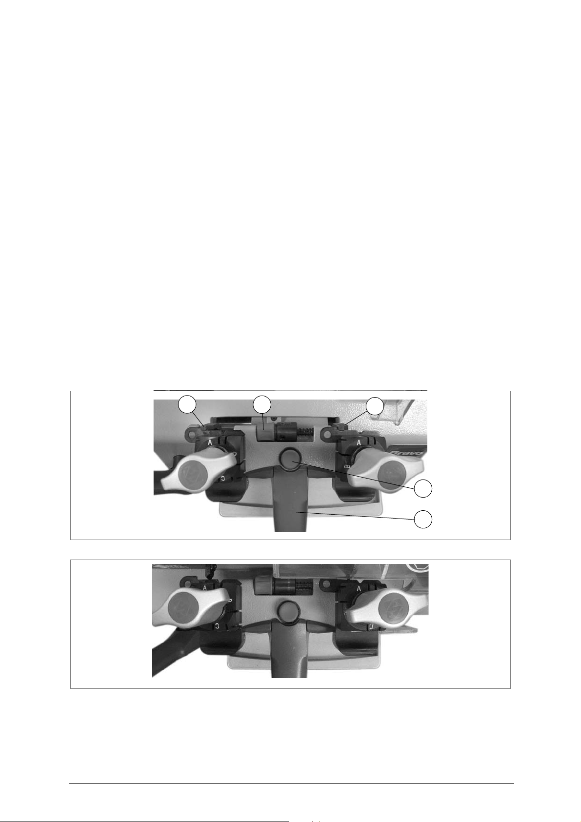
5.12 Mechanical calibration (without electric contact)
D
EPTH CALIBRATION
Depth calibration is regulation of the cutting depth (fig. 12, page 14). Proceed as follows:
1) Turn off the master switch (C) to operate safely and prevent activation of the cutting tool.
2) Place the adjusting key (provided) in the clamps (fig.16) with the notch facing the cutting tool and
tracer point and proceed as follows:
a) ensure that the keys adhere to the clamps and that the callipers (K) are in full contact with the
stops.
b) to take the callipers into contact with the keys, rotate the drum (R) towards you (away from
you to return to the ideal position)
ATTENTION: the carriage will be released only if the callipers are in the ideal position.
3) Release the carriage by lowering the knob (V) and pressing the push button (Q) right down (fig.16).
4) Raise the carriage and take up to the cutting tool.
5) Take the flat part of the key into contact with the cutting tool and tracer point (fig.17).
6) Turn the cutting tool by hand in the opposite direction to rotation and check that it skims the adjusting
key at different points.
7) If necessary regulate the cutting tool depth with the micrometric tracer point, as follows:
a) loosen the screw locking the tracer point (J2) (fig. 18, page 17).
b) turn the knob (O) clockwise to move the tracer point forwards.
c) turn the knob (O) anticlockwise to move the tracer point backwards (each mark on the
graduated drum equals a variation of 0.05 mm).
8) If necessary, repeat the regulation operation a number of times. Tighten the screw (J2) before
checking skimming (point 6).
9) Zero the tracer point by taking the reference index on the handwheel (O1) to the white mark on the
graduated drum, as described below:
a) with one hand hold still the knurled part of the knob (O).
b) with the other hand turn the mobile part below it (O1).
:
Fig. 16
Fig. 17
16 Copyright Silca 2011
Page 21
Operating manual - English BRAVO MAXIMA II
KB1
R
O1O VJ2
B2 B
A
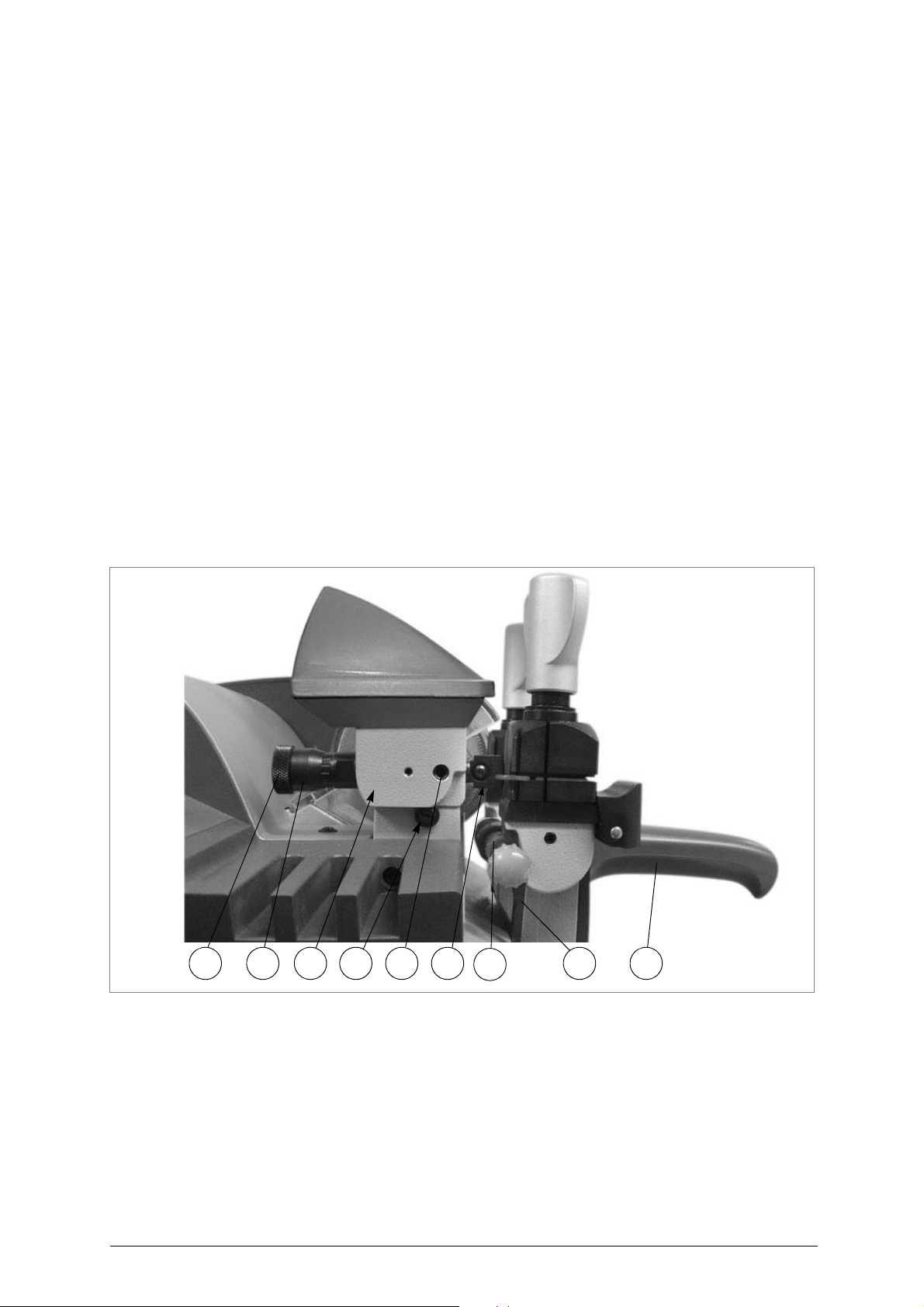
XIS CALIBRATION
Axis calibration is regulation of the cutting space on the key (fig.12, pag.14). Proceed as follows:
1) Turn off the master switch (C) to operate safely and prevent activation of the cutting tool.
2) Place the adjusting key in the clamps (fig.18) with the notch facing the cutting tool and tracer point and
proceed as follows:
a) ensure that the keys adhere to the clamp and that the callipers (K) are in full contact with the
stops.
b) to take the callipers into contact with the keys, rotate the drum (R) towards you (away from
you to return to the idle position).
ATTENTION: the carriage will be released only if the callipers are in the ideal position.
3) Release the carriage by lowering the knob (V) and pressing the push button (Q) right down (fig. 16,
page 16).
4) Move the adjusting key so that the notch comes into contact with the cutting tool (A) and tracer point
(B).
5) Turn the cutting tool one full turn by hand in the opposite direction to rotation.
6) Check that the cutting tool skims the two sides of the notch.
7) If necessary, regulate the micrometric tracer point, as follows:
a) loosen the screw (J1) to move the tracer point (fig. 15, page 15).
b) move the tracer point (B1) to the side by loosening or tightening the screw (B2).
c) when skimming is satisfactory (point 5), tighten the screw (J1) all the way, without exerting
pressure.
8) Lower the carriage by means of the handle (V) (it will engage automatically).
9) Remove the adjusting key.
ATTENTION: when adjusting keys have been repeatedly sc ratched by the cutting tool, they m ust be replaced .
They can be replaced by two identical key blanks.
:
Fig. 18
Copyright Silca 2011 17
Page 22
BRAVO MAXIMA II Operating manual - English
K
stop bar
E1
Attention
:
With loosened handle (F) a
light rotation of the clamp is
sufficient (gripping by the 2
jaws) to turn it to the
required side. Alignment is
automatic and guaranteed
by the mobile pressure
device (E1).
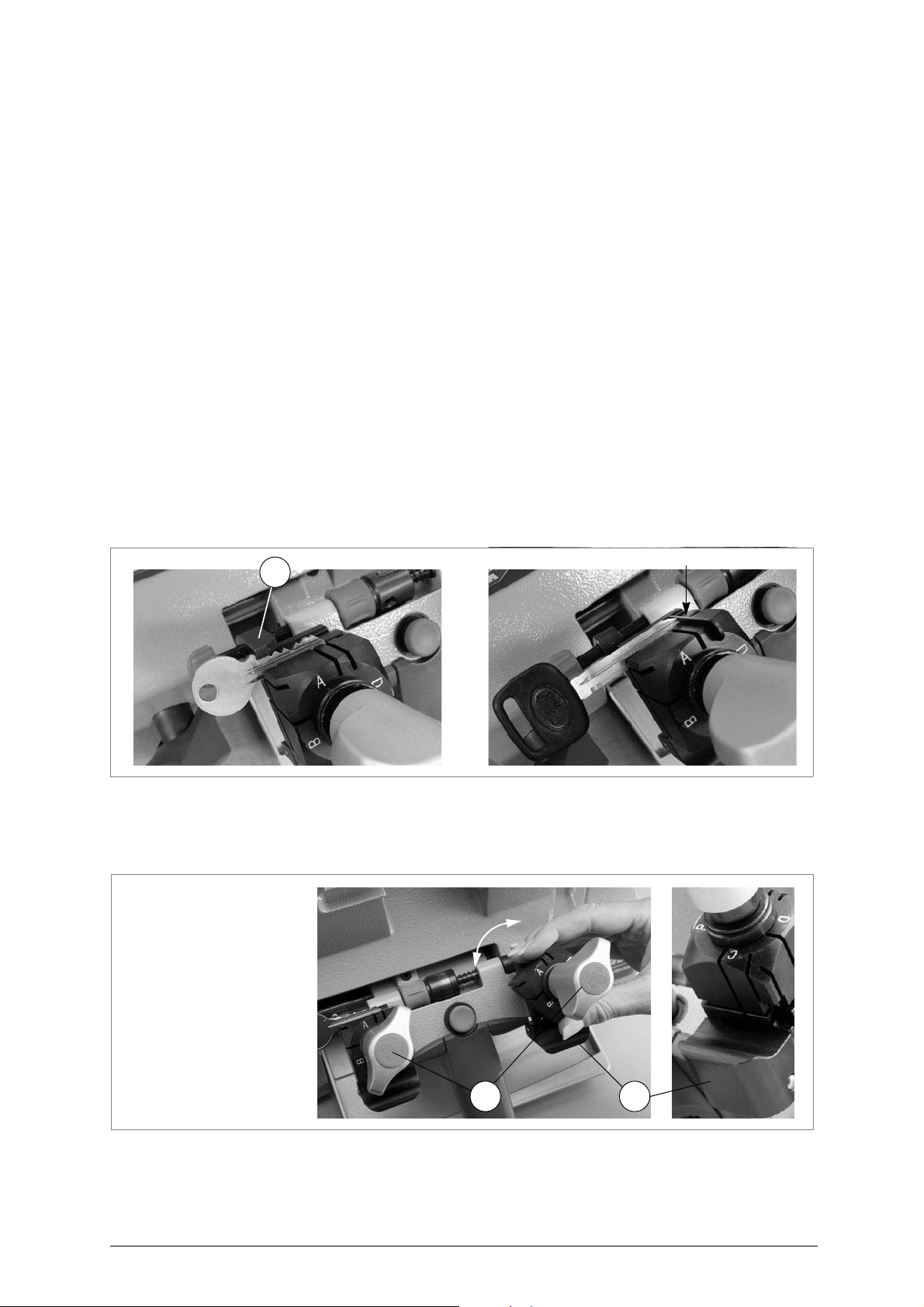
F
6 CUTTING OPERATIONS
ATTENTION: for complete safety during the cutting operations, take the following precautions:
• Always work with dry hands.
• Check that the machine is properly earthed.
• Wear protective goggles even if the machine has a protective shield over the cutting tool.
• Start the motor (switch P) only after completing the operations on the carriage (sec uring the
keys, etc.).
• Keep hands away from the cutting tool in motion.
6.1 Key cutting
When BRAVO MAXIMA has been turned on by means of push button (C), it is ready for cutting but the
cutting tool is not rotatin g (because the carriage is held in the idle posit ion). Now the ori ginal key and
the blank can be placed in the jaws, ready for cutting.
S
ECURING THE KEYS IN THE JAWS
Position the key blank (right-hand jaw) and original (left-hand jaw), ensuring that:
a) the keys are resting properly on the bottom of the jaw.
b) the key stop butts against the ga uge (K) or, in the absence o f a stop, the tip of the key is
against the stop bar (fig.19).
c) close the jaws by turning the knobs (F).
ATTENTION: the knobs are gauged so that they do not exert too much pressure for closing (if pres sure is too
high they only idle), which would damage the key and the parts of the clamp (including the
knob).
Fig. 19
Fig. 20
ATTENTION:
18 Copyright Silca 2011
TO
TURN THE CLAMPS
:
With loosened handle (F) a light rotation of the clamp is sufficient (gripping by the 2 jaws) to
turn it to the required side. Alignment is automatic and guaranteed by the mobile pressure
device (E1)
• for keys placed flat, such as those with cuts on one side only, po sition the c lamps as s hown
in fig. 6, page 8.
• for keys with cuts on both sides, turn the clamps as shown in fig.6.
(fig.20).
Page 23
Operating manual - English BRAVO MAXIMA II
K
AB C
E
U
SING THE PINS
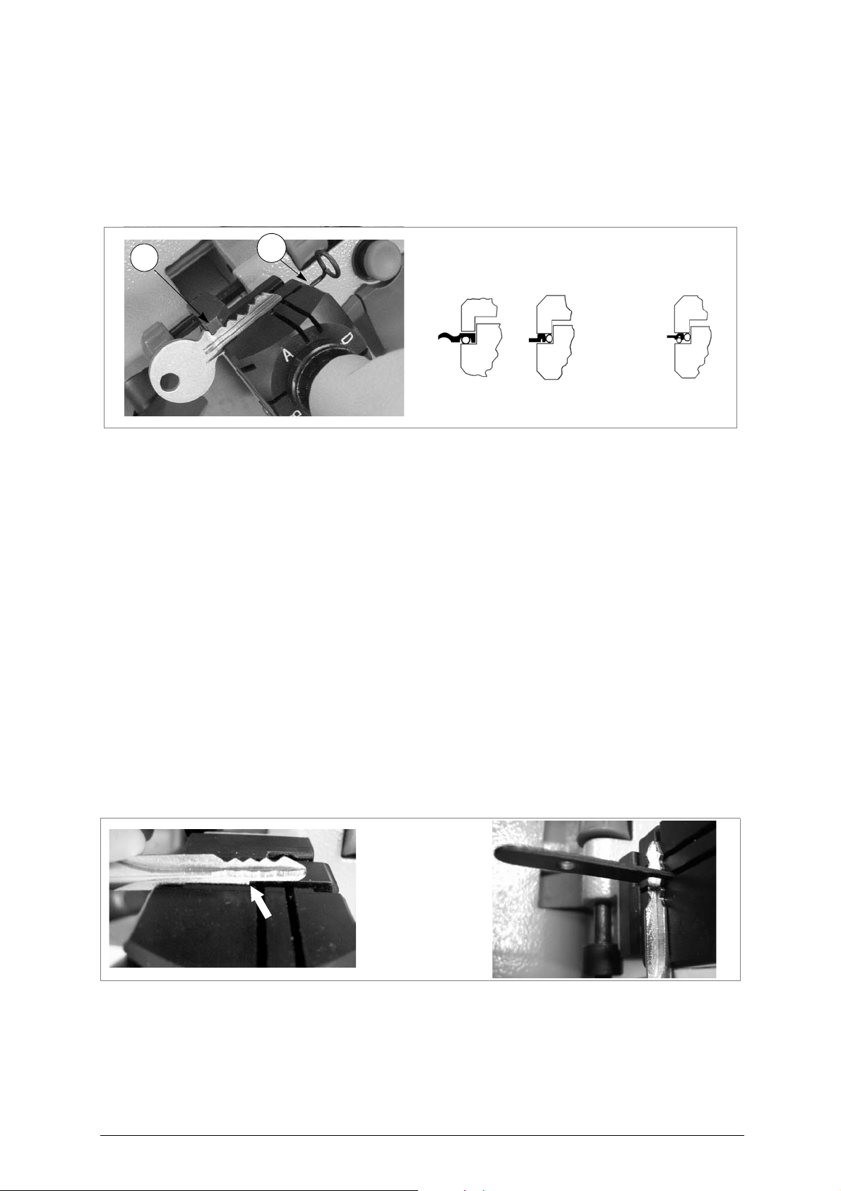
For keys with narrow or thin stems one pin must be used (fig. 21-A, fig. 21-B).
For keys with narrow, thin stems, two pins must be used (fig. 21-C), the second one to give a secure
grip on the key.
ATTENTION: the diameter of the pin used for the original key must be th e same as that use d for the key blank,
ATTENTION: never exchange the clamps.
Fig. 21
so that the two keys are secured in identical positions in the jaws.
6.2 Cutting cruciform keys (with 3 fins)
Ordinary or 4 sided clamps can be used to cut almost all cruciform keys (e xcept Y an d T shaped ones)
(fig. 7, page 9).
Positioning cruciform keys:
1) Leave the gauges in the idle position.
2)
Fit the original key into the left-hand clamp
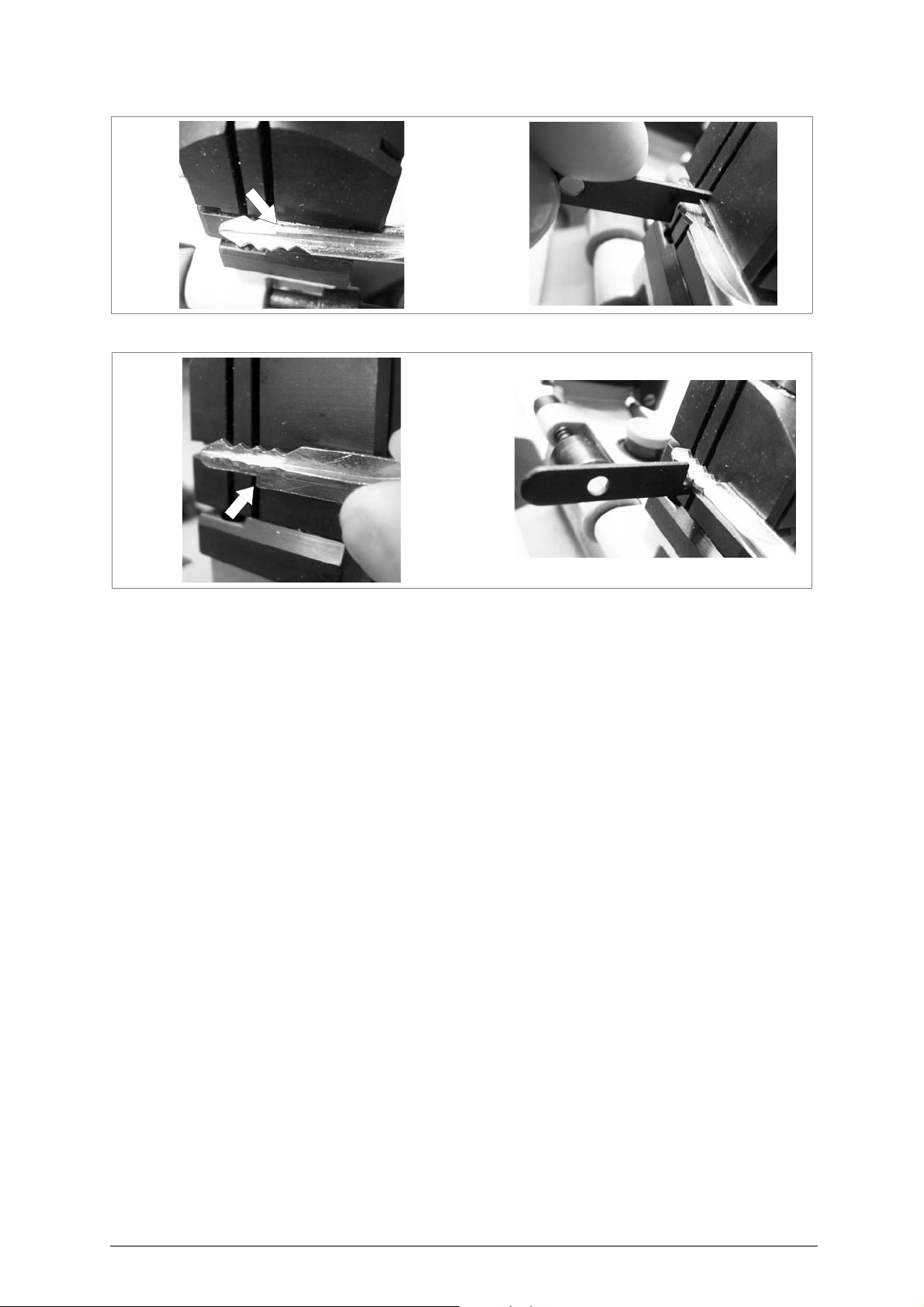
- insert the grooved bar into the notch on the clamp according to the key stop (as shown in fig.22,
fig.23 and fig.24).
- butt the key stop up against the bar.
3)
Tighten the knob (F) to secure the key
4)
Remove the bar
5)
Repeat the same procedure on t he other clamp holding the ke y blank to be cut (pay a ttention to the
corresponding fin
6)
Remove the bar
Cut the first fin
7)
8)
Turn the keys in the same direction to cut the other fins
ATTENTION: the cuts on each fin are different.
.
).
.
.
POSITION OF KEY AND BAR
:
.
.
Fig. 22 - Key stop towards the INNER part of the clamp
Copyright Silca 2011 19
Page 24
BRAVO MAXIMA II Operating manual - English
Fig. 23 - Key stop UP
Fig. 24 - Key stop DOWN
20 Copyright Silca 2011
Page 25
Operating manual - English BRAVO MAXIMA II
H1
H
7 CLEANING AND
ATTENTION: for repairs or replacement of parts for maintenance, the ‘CE ’ m ark is guara nte ed only if orig ina l
spare parts provided by the manufacturer are used.
Although the BRAVO MAXIMA key-cutting machine does not require special maintenance, it is
advisable to check and, i f necess ary, repl ace the parts subj ect to we ar, such a s: the b elt, cutt ing tool,
brush, tracer point. Replacement is simple and can be carried out by the operator.
CLEANING: keep the carriage and clamps free of chippings from the cutting operations by
cleaning with a dry brush.
ATTENTION: DO NOT USE COMPRESSED AIR!
ATTENTION: to keep the machine well maintained we recommend using protective oil, e.g. WD40 or similar,
applied to the burnished mechanical parts. This prevents oxidation of the parts in question
(clamps, guides, carriages, etc.).
Before starting any type of maintenance (checks or replacements), read the instructions below:
• never carry out maintenance or servicing with the machine switched on.
• always remove the mains plug.
• follow all the instructions in the manual to the letter.
• use original spare parts.
• always check that screws and nuts are properly tightened.
MAINTENANCE
7.1 Preparing for maintenance
Follow the procedure described below when carrying out maintenance or servicing the BRAVO
MAXIMA:
• turn off the master switch (C) (fig. 5, page 6).
• remove the mains plug.
• lock the carriage (D) if maintenance is to be carried out on any of its parts or on parts with
which it comes into contact (cutting tool and tracer point).
7.2 Replacing the cutting tool
To replace a worn cutting tool, proceed as follows:
1) Turn the machine off and unplug it.
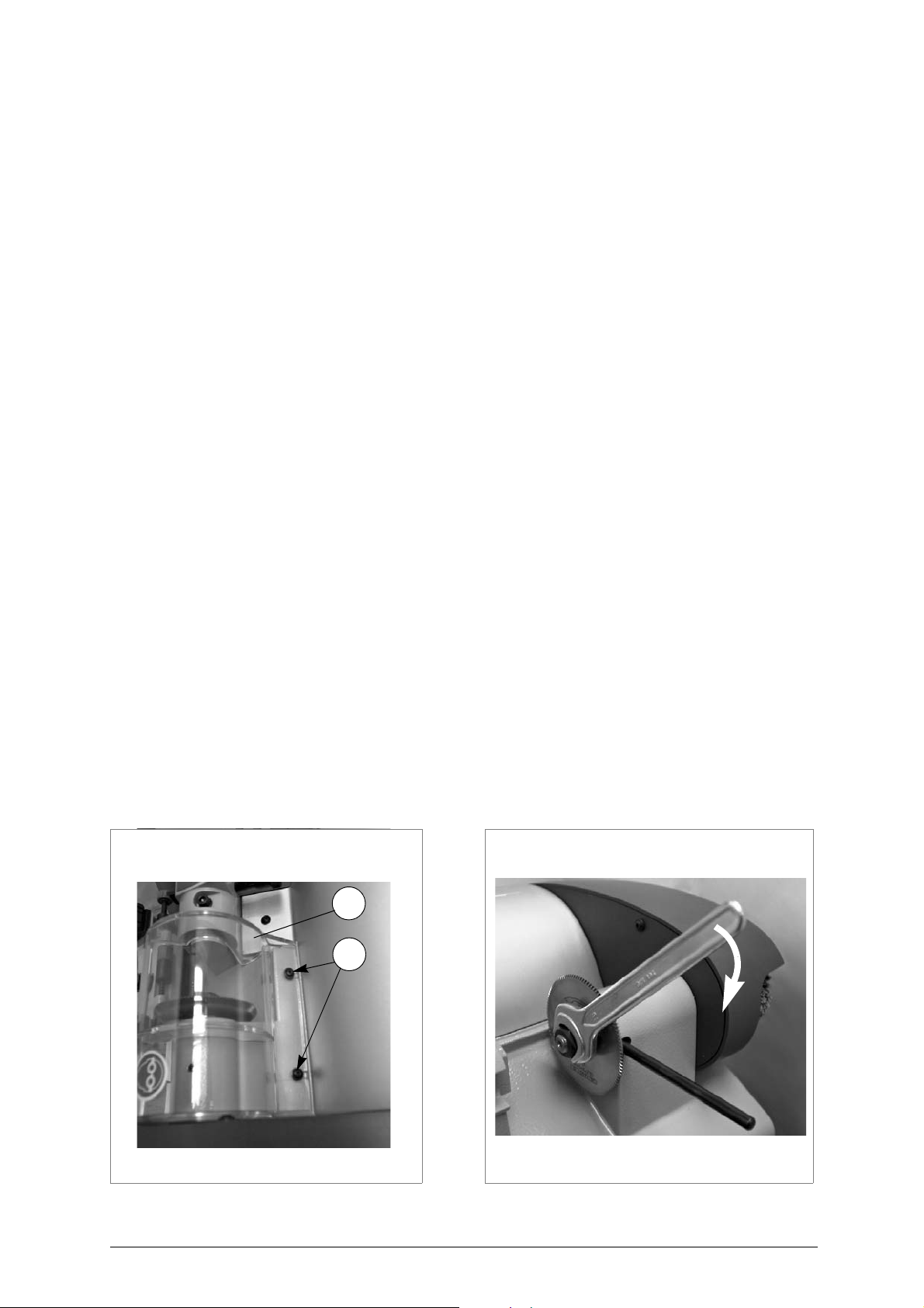
2) Remove the cutter locking screw (H1) and remove the cutter protective shield (H) (fig.25).
3) Place the locking pin into the groove in the base and the special hole in the cutting tool shaft (fig.26).
4) With the spanner provided loosen the cutting tool locking nut.
ATTENTION: the thread is left-handed.
5) Carefully clean the new cutting tool and all the parts which come into contact with it.
6) Replace the cutting tool and tighten the nut.
ATTENTION: the tool rotates clockwise.
7) Remove the locking pin and fix the shield (H) with screw (H1).
Fig. 25
Fig. 26
Copyright Silca 2011 21
Page 26
BRAVO MAXIMA II Operating manual - English
B
J
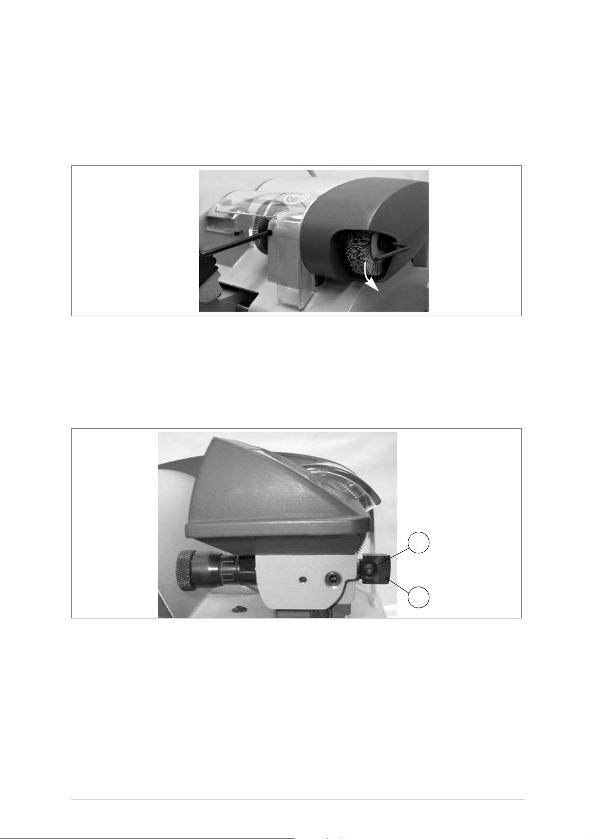
7.3 Replacing the brush
When the brush no longer cleans off the burrs it must be replaced as follows:
1) Turn the machine off and unplug it.
2) Place the locking pin into the groove in the base and into the special hole in the cutter shaft (fig.27).
3) Use the Allen wrench to loosen the screw holding the brush in place.
4) Replace the brush and tighten the screw with the Allen wrench.
5) Remove the locking pin.
Fig. 27
7.4 Replacing the tracer point
To replace the tracer point, proceed as follows:
1) Turn the machine off and unplug it.
2)
Loosen and remove the screw (J) and remove the tracer point
3)
Place the new tracer point in position and fix with the screw
4) Re-calibrate the machine, following the procedure described in chapter 5.10 on page 14.
Fig. 28
(B) (fig.28).
(J).
22 Copyright Silca 2011
Page 27
Operating manual - English BRAVO MAXIMA II
0,1 mm
3 mm
10 mm
vaschetta
porta fusibili
U
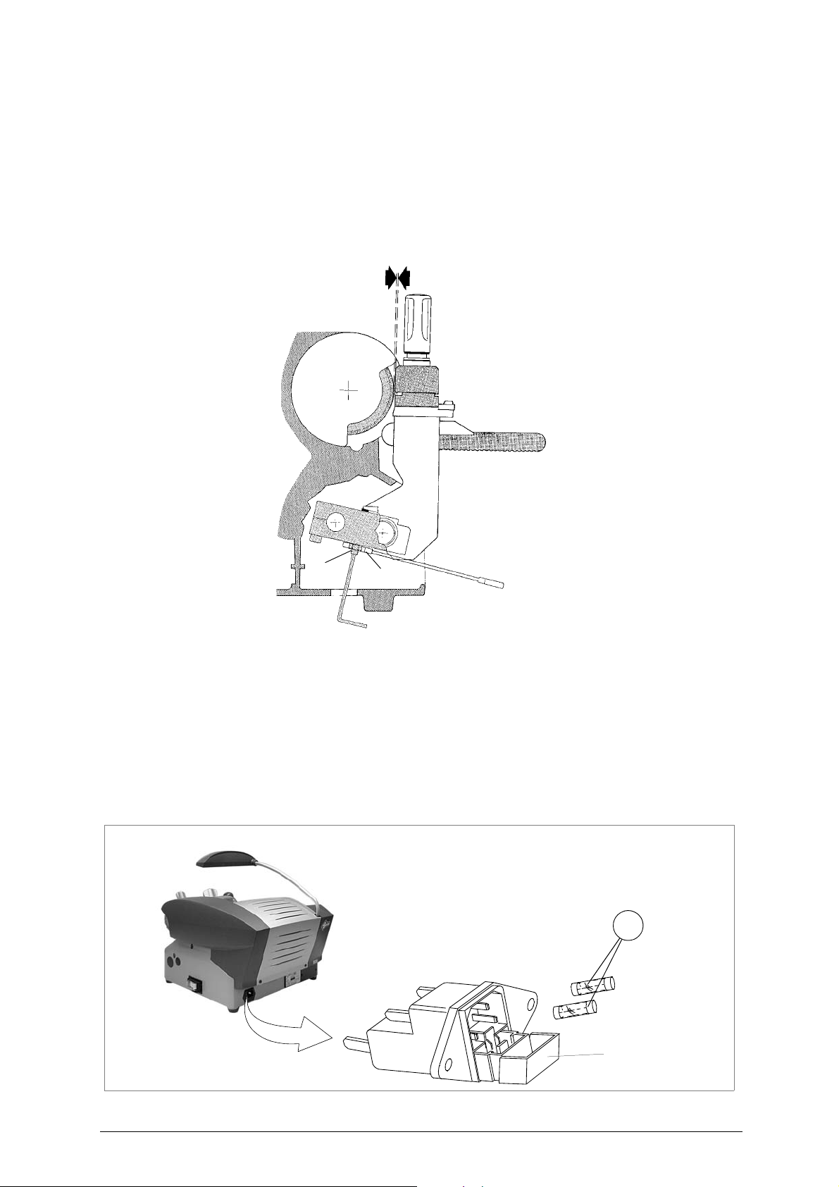
7.5 Regulating of maximum carriage depth
To prevent damage to the clamps and cutting tool, maximum cutting depth must be established.
ATTENTION: the distance between the cutting tool/tracer point and clamp must be 0.1 mm. If this is not the
case, proceed as follows:
1) Turn the machine off and unplug it.
2) Release the carriage and raise (against the cutting tool) at the end of run (fig.29).
3) Remove the chippings tray.
4) Use the 10 mm spanner to release the nut.
5) Use the 3 mm Allen wrench to regulate the grub screw, through the hole on the bottom of the machine.
6) Tighten the nut.
Fig. 29
7.6 Replacing the fuses
ATTENTION: fuses must always be replaced with others of the same type (rapid) and with the same Amps (5
Amps).
1) Turn the machine off and unplug it.
2) Turn the key-cutting machine so that the fuse box is easily reached.
3) Remove the fuses box placed below the key-cutting machine socket (fig.30).
4) Replace the fuses (U).
5) Close the fuses box and connect the power cable.
Fig. 30
Copyright Silca 2011 23
Page 28
BRAVO MAXIMA II Operating manual - English
W1
W2
W
W4
1432
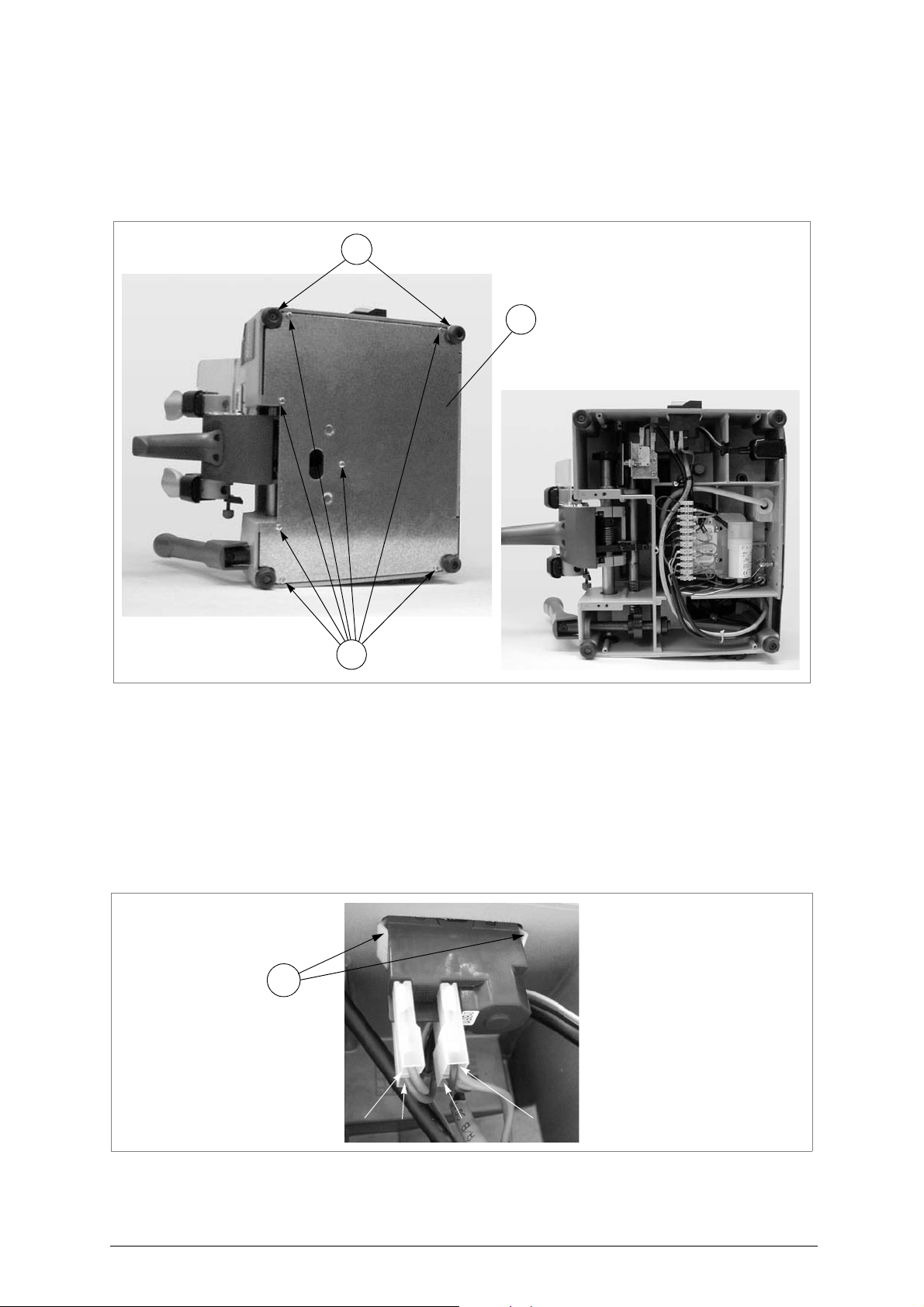
7.7 Access to bottom compartment
1) Turn the machine off and unplug it.
2) Remove the swarf tray.
3)
Turn the machine onto its left-hand side
4) Loosen the 7 screws (W) and 2 feet (W1) and remove the bottom safety plate (W2) (fig.31).
.
Fig. 31
7.8 Replacing the master switch
1) Turn the machine off and unplug it.
2) Remove the bottom panel (see ch. 7.7).
3) Detach the various connectors (1, 2, 3, 4) paying careful attention to their positions (fig.32).
4) Press on the 2 tabs (W4) on the switch and pull it out.
5) Fit the new switch properly, taking care to secure it well (tabs).
6) Reconnect the various connectors (1, 2, 3, 4).
7) Replace the bottom safety plate and fix with the 7 screws (W) and 2 feet. Fit the swarf tray.
Fig. 32
24 Copyright Silca 2011
Page 29
Operating manual - English BRAVO MAXIMA II
Z1
Z
Z2
Z2
1
2
Y
Y1
Y2
Y3
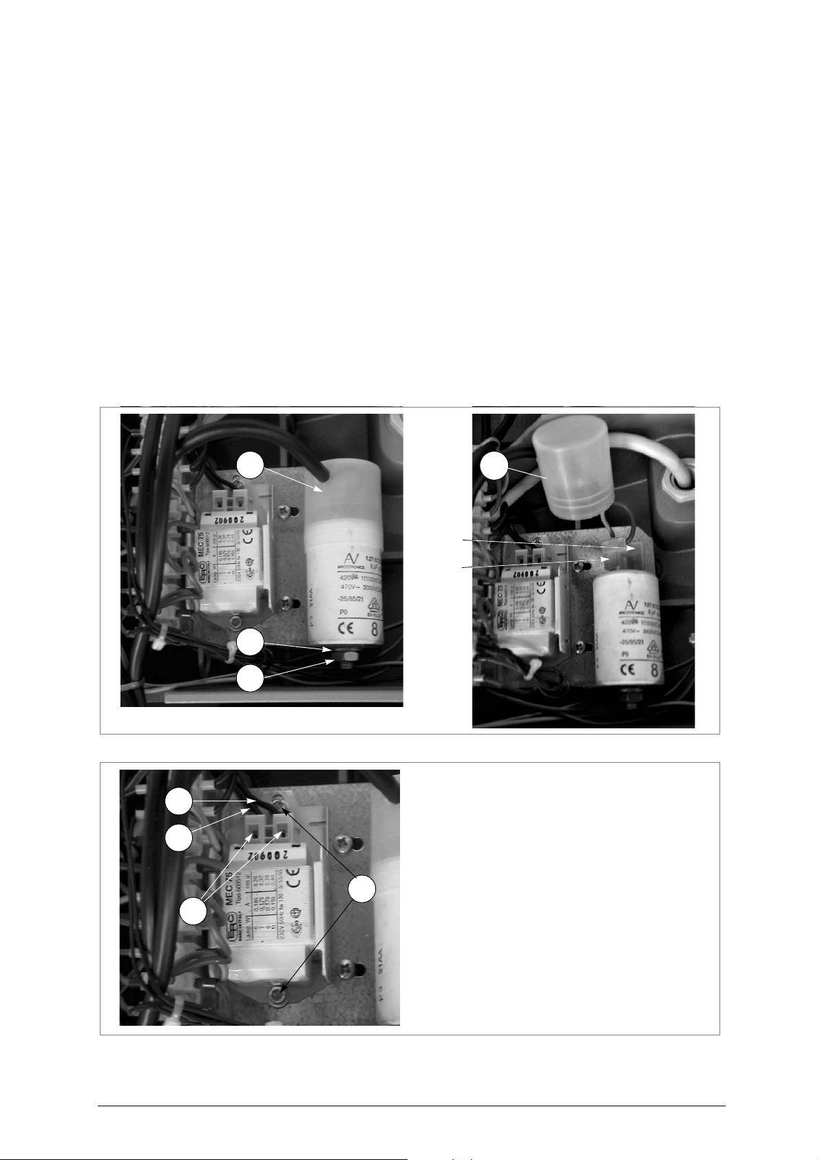
7.9 Replacing the condenser (motor) and/or feeder (lamp)
1) Remove the bottom panel (see ch. 7.7).
CONDENSER
1)
Loosen the nut (Z) and remove the washer (Z1) and condenser
2)
Fit the new condenser and fix with the washer (Z1) and nut
3)
Remove the cap (Z2) from the new condenser
4)
Remove the cap from the old condenser and detach the connectors (1 and 2) from the old
condenser to connect them to the new one, paying attention to their positions
5)
Replace the cap (Z2) on the new condenser
6)
Replace the bottom safety plate, fix with the 7 screws (W) and 2 feet (fig. 31, page 24). Fit the
swarf tray
LAMP REACTOR
1)
Loosen the 2 screws (Y) and remove the reactor
2) Use the tip of a small screwdriver to enter the slits (Y1) and detach the 2 wires (Y2), (Y3).
3) Fit the 2 wires (Y2), (Y3) into the special connections on the new reactor.
4) Place the new reactor in its seat and secure with the 2 screws (Y).
5) Replace the bottom safety plate and fix with the 7 screws (W) and 2 feet (W1) (fig. 31, page 24). Fit
the swarf tray.
.
.
.
(fig.34).
(fig.33).
(Z).
.
Fig. 33
Fig. 34
Copyright Silca 2011 25
Page 30
BRAVO MAXIMA II Operating manual - English
Q1
123
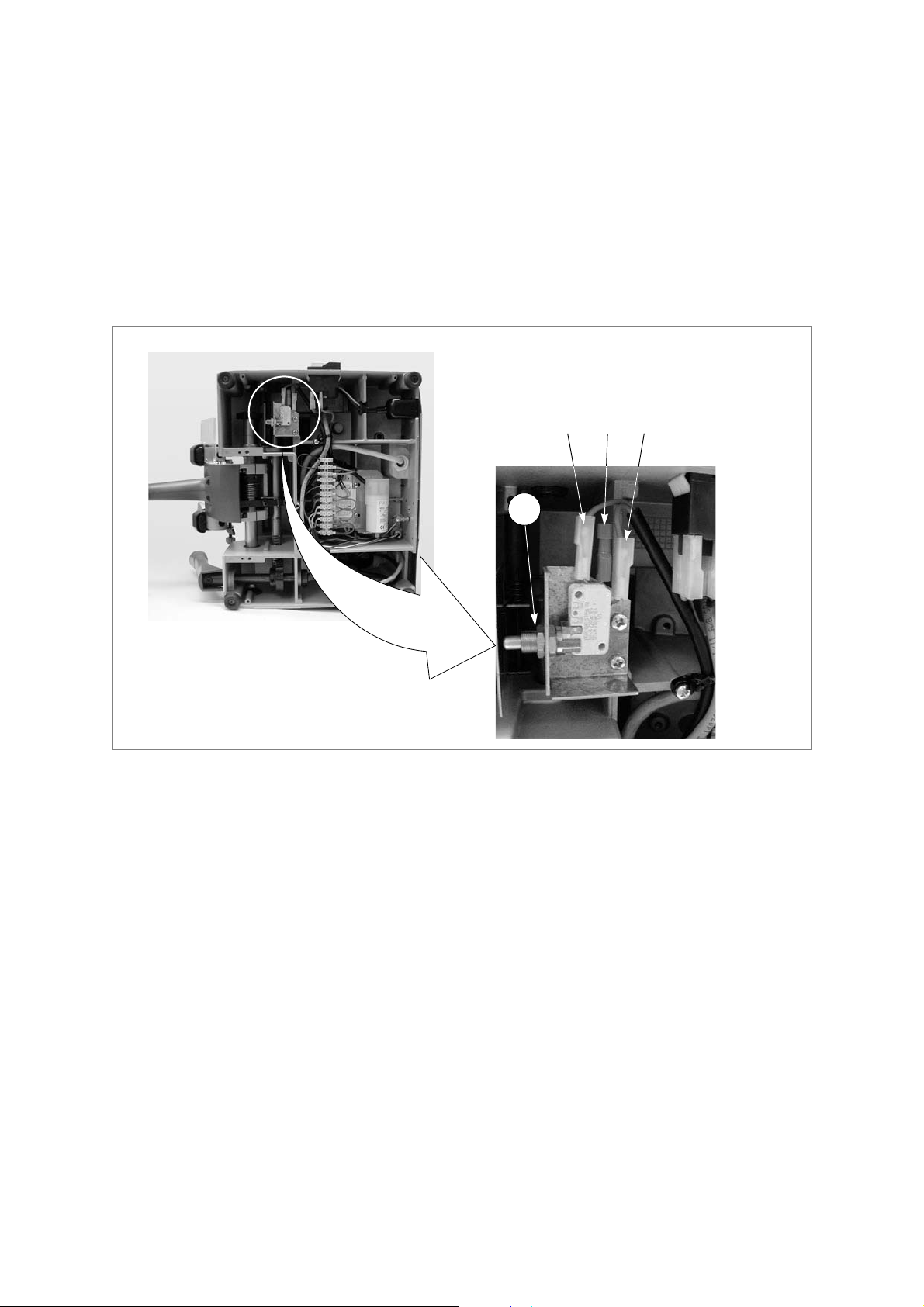
7.10 Replacing the microswitch
1) Turn the machine off and unplug it.
2)
Release the carriage and leave it in the working position (towards the tracer point
3) Remove the bottom panel (ch.7.7, page 24).
4)
Loosen the nut (Q1) and remove the microswitch
5)
Detach the connectors (1, 2 and 3) paying attention to their positions
6)
Fit the new microswitch into the seat of the previous one, and secure with the nut
7)
Connect the connectors
8)
Raise and lower the carriage to check that the microswitch works properly (click
9)
Replace the bottom safety plate and secure with the 7 screws (W) and 2 feet (W1) (fi g. 31, page
24). Fit the swarf tray
(1, 2 and 3).
.
(fig.35).
.
).
(Q1).
).
Fig. 35
26 Copyright Silca 2011
Page 31
Operating manual - English BRAVO MAXIMA II
C2
C1
C3
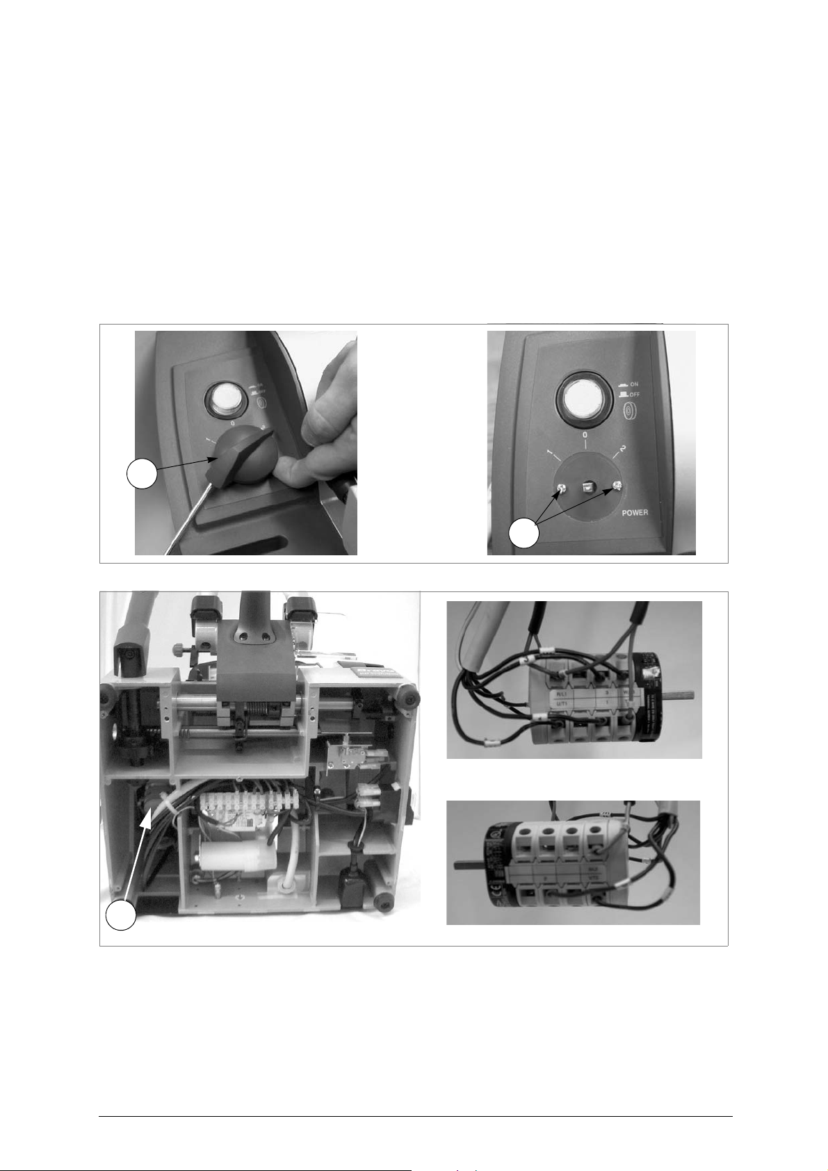
7.11 Replacing the commutator
1) Turn the machine off and unplug it.
2) Remove the swarf tray.
3) Pull out the commutator (C) knob (C1) and loosen the 2 fixing screws (C2) (fig.36).
4) Turn the machine onto its back side.
5) Loosen the 7 screws (W) and 2 feet (W1) and remove the bottom safety plate (W2) (fig.31, pag.24).
6) Pull the commutator (C3) downwards and disconnect the wires from their connections in order to
remove (fig.37).
7) Connect the wires to the new commutator.
8) Push into its seat and fix with the 2 screws (C2) (fig.36).
9) Replace the bottom safety plate, fix with the 7 screws (W) and 2 feet.
10)Place the machine upright again. Fit the swarf tray.
11)Fit the commutator knob (C1).
Pay attention to their position
.
Fig. 36
Fig. 37
Copyright Silca 2011 27
Page 32
BRAVO MAXIMA II Operating manual - English
H1
H
T1
T2
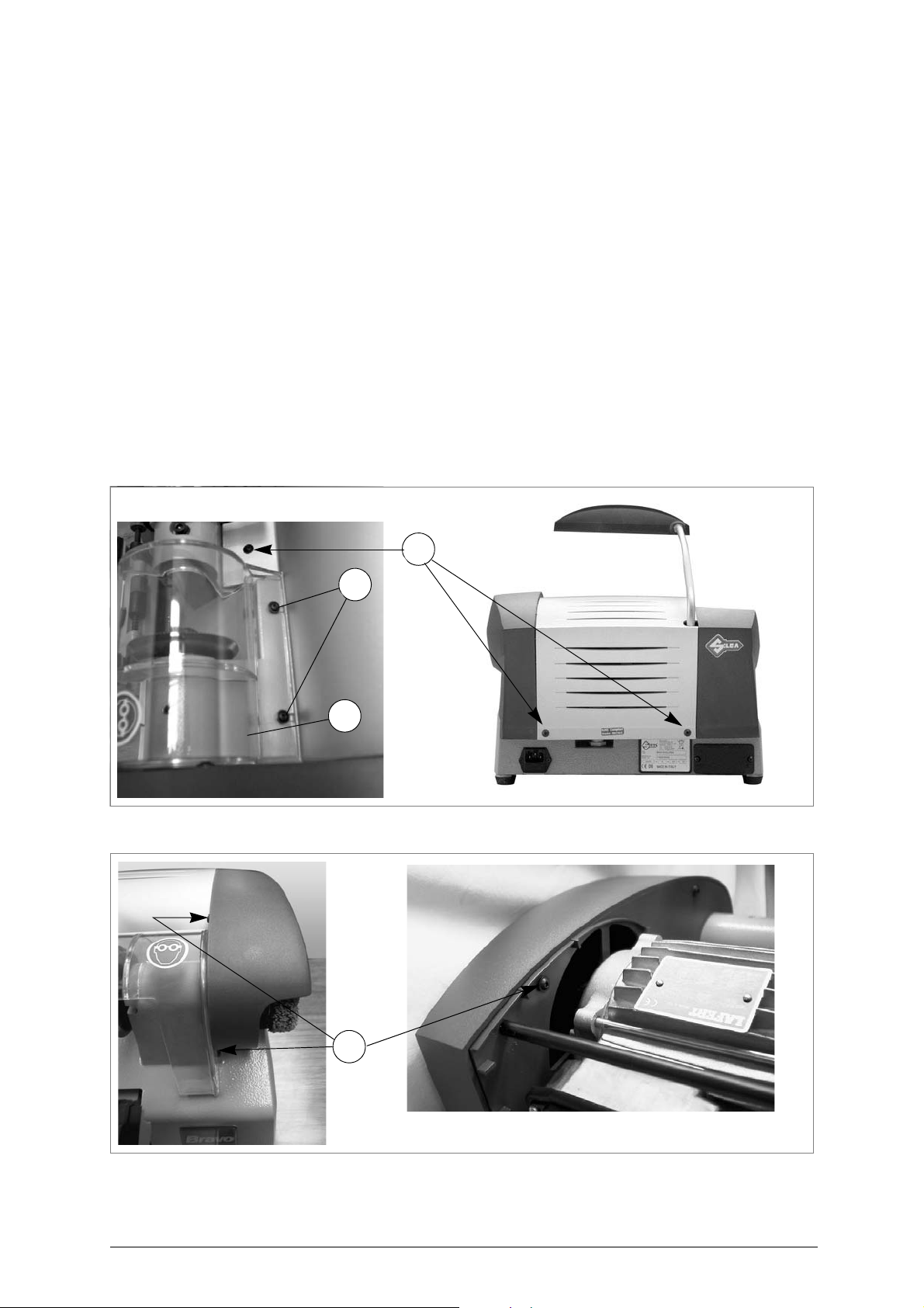
7.12 Replacing the push button
1) Turn the machine off and unplug it.
2)
Loosen the 2 screws (H1) on the cutter cover (H) and remove
3) Loosen the 3 screws (T1) on the central cover, raise slightly and remove, tipping a little.
4) Loosen the 3 screws (T2) (fig.39) on the belt cover and remove (pull out towards the front of the
machine).
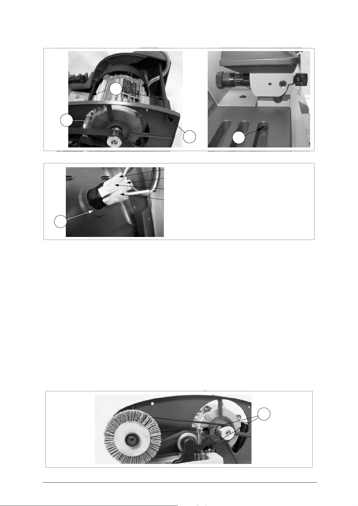
5) Remove the belt (ch.7.13, page 29).
6) Loosen the nuts (U1) on the stay bolts (U2) and remove together with their washers (fig. 40, page 29).
7) Loosen the stay bolts (U2) (fig.40) and remove.
8) Loosen the screw (U3) on the left-hand cover (fig.40).
9) Raise the left-hand cover to gain access to the switches.
10)Remove the connectors (1, 2, 3, 4), paying attention to their positions (fig. 41, page 29).
11)Press the tabs (W4) in order to remove the push button.
12)Fit the new push button, taking care that it is well secured (tabs).
13)Reconnect the various connectors (1, 2, 3, 4).
14)Replace the left-hand cover and tighten the screw (U3)
15)Fit the stay bolts (U2), screw onto the left-hand cover and secure with the washer and nut (U1).
16)Replace the belt cover and tighten the 3 screws (T2).
17)Replace the central cover and tighten the 3 screws (T1)
18)Replace the cutter cover and tighten the 2 screws (H1).
(fig.38).
Fig. 38
Fig. 39
28 Copyright Silca 2011
Page 33
Operating manual - English BRAVO MAXIMA II
U1
U2
U1
U3
W4
1
2
3
4
U4
Fig. 40
Fig. 41
7.13 Replacing and/or tightening the belt
1) Turn the machine off and unplug it.
2)
Loosen the 2 screws (H1) on the cutter cover (H) and remove
3)
Loosen the 3 screws (T1) on the central cover (fig.38), raise slightly and remove, tipping a little
4)
Loosen the 3 screws (T2) (fig. 39, page 28) on the belt cover and remove (pull towards the front
of the machine
TIGHTENING
-
screw the screw/nut (U4) until the belt is properly tightened
REPLACEMENT
-
loosen the screw/nut (U4) to lower the belt tightening pulley
remove the existing belt, turn the bigger pulley manually, exerting a little pressure on the belt (on
the motor pulley) and take out of it s se at
fit the new belt, placing it in the motor pulley then (forcing a little) in the bigger pulley, turning it
manually
5) Tighten the screw/nut (U4) until the belt is properly tightened.
6) Replace the belt cover and fix with the 3 screws (T2) (fig. 39, page 28).
7) Replace the central cover and fix with the 3 screws (T1) (fig. 38, page 28).
8) Replace the cutter cover and fix with the 2 screws (H1).
(*) Should the tightening be difficult to do, loosen the 4 fixing screws and move the motor until
it is properly placed. Tighten the 4 fixing screws.
).
:
:
.
.
(fig. 38, page 28).
.
(fig.42).
.
Fig. 42
Copyright Silca 2011 29
Page 34
BRAVO MAXIMA II Operating manual - English
U5
U7
U7
U6
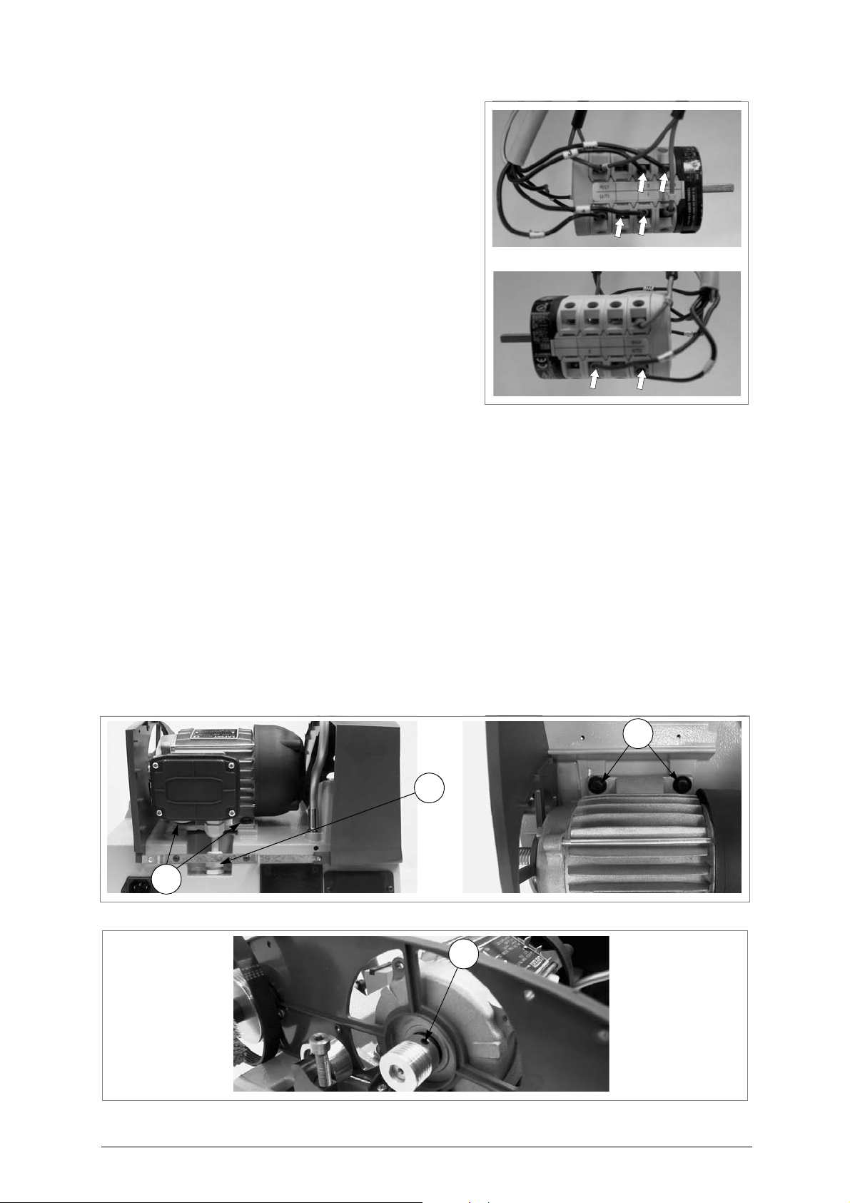
7.14 Replacing the 2 speed motor
1) Turn the machine off and unplug it.
2) Remove the swarf tray.
3)
Loosen the 2 screws (H1) on the cutter cover (H)
and remove
4) Loosen the 3 screws (T1) on the central cover, raise
slightly and remove, tipping a little (fig. 38, page 28).
5) Loosen the 3 screws (T2) (fig. 39, page 28) on the
belt cover and remove (pull towards the front of the
machine).
6) Pull the commutator knob (C1) off and loosen the 2
fixing screws (C2) (fig.36, pag.27).
7) Turn the machine onto its back-hand side.
8) Loosen the 7 screws (W) and 2 feet (W1) and
remove the bottom safety plate (W2) (fig. 31, page
24).
9) Pull the commutator downwards (fig. 37, page 27)
and disconnect the 6 motor wires from their
connections (fig.43).
10)Loosen the fairlead (U5) (fig.44).
11)Loosen the grub screw/nut (U4) (fig.42) in order to lower the belt tightening pulley and pull the belt off
the motor pulley.
12)Loosen the 4 fixing screws on the motor (fig.44) and remove, paying attention to the wire.
13)Loosen the grub screw (U6) on the motor pulley (fig.45). Remove the pulley and fit to the new motor.
Secure by tightening the grub screw (U6).
14)Fit the new motor into its housing, taking care to put the wires through first, then secure with the 4
screws (U7).
15)Tighten the fairlead (U5).
16)Fit the belt, first in the motor pulley then (forcing a little) in the bigger pulley, turning manually.
17)Tighten the grub screw/nut (U4) until the belt is properly tightened (fig. 42, page 29).
18)Replace the belt cover and fix with the 3 screws (T2) (fig. 39, page 28).
19)Replace the central cover and fix with the 3 screws (T1) (fig. 38, page 28).
20)Replace the cutter cover and fix with the 2 screws (H1) (fig.38).
21)Turn the machine onto its back-hand side.
22)Connect the 6 motor wires to the commutator (fig.43).
23)Push the commutator upwards to replace it in its ideal seat. Fix with the 2 screws (C2). Fit the knob
(C1) (fig. 36, page 27).
24)Replace the bottom plate and fix with the 7 screws (W) and 2 feet. Fit the swarf tray.
(fig. 38, page 28)
.
Fig. 43
Fig. 44
Fig. 45
30 Copyright Silca 2011
Page 35
Operating manual - English BRAVO MAXIMA II
S1
S
V2 V
D1
V1
Z
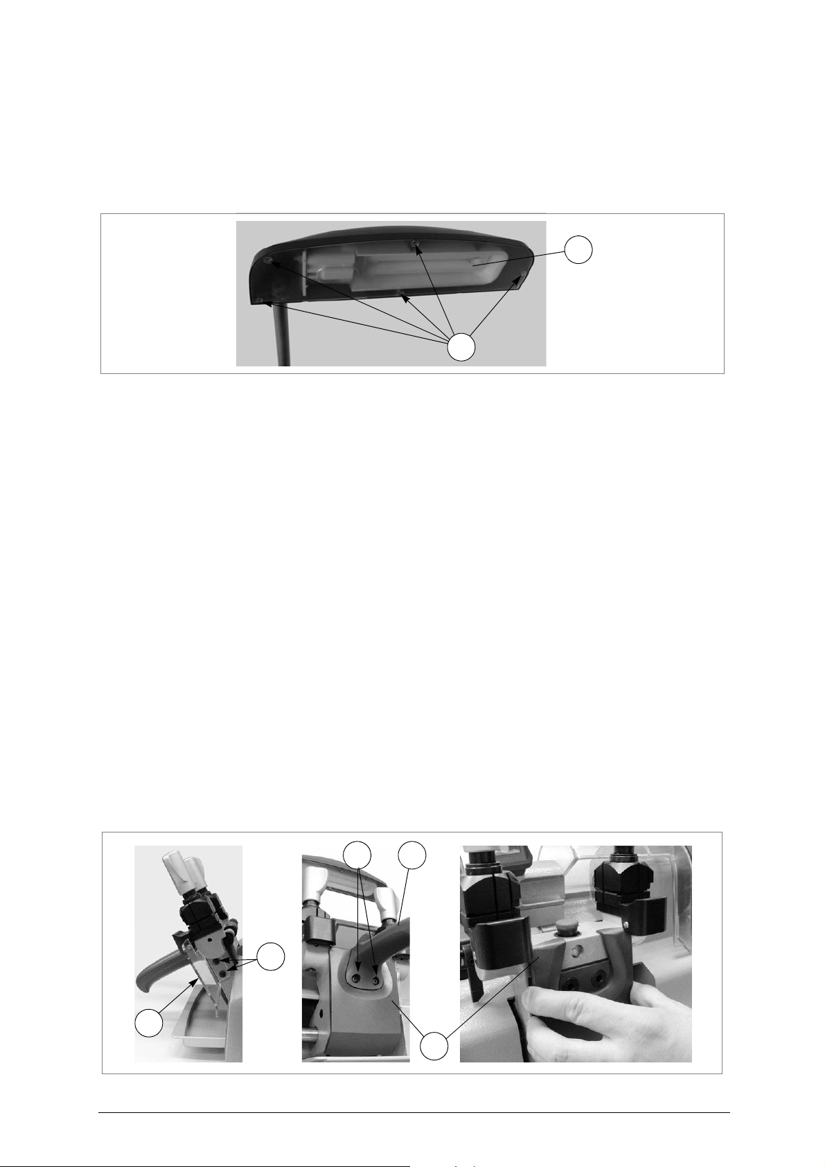
7.15 Replacing the light bulb
1) Turn the machine off and unplug it.
2)
Fig. 46
Loosen the 5 screws (S1) on the lamp shield and remove
3)
Remove the bulb (S) taking care not to use pointed utensils for this operation
4)
Fit the new bulb
5)
Replace the lamp shield and tighten the 5 screws (S1) to secure
.
.
.
.
7.16 Replacing carriage spring
1) Turn the machine off and unplug it.
2) Loosen the 2 screws (V1) and remove the protection from swarf (Z) (fig.47).
3)
Release the carriage and leave it in the working position (towards the tracer point
4)
Loosen the 2 screws (V2) on the carriage knob
5)
To remove the knob (V), raise a little and pull off
6)
Remove the plastic safety shield (D1) on the carriage
7)
Loosen the 2 screws (D2) on the carriage
8)
Remove the caps (D3) from the base
9)
Remove the swarf tray
10)
Turn the machine onto its back
11)
Loosen the 7 screws (W) and 2 feet (W1) and remove the bottom panel
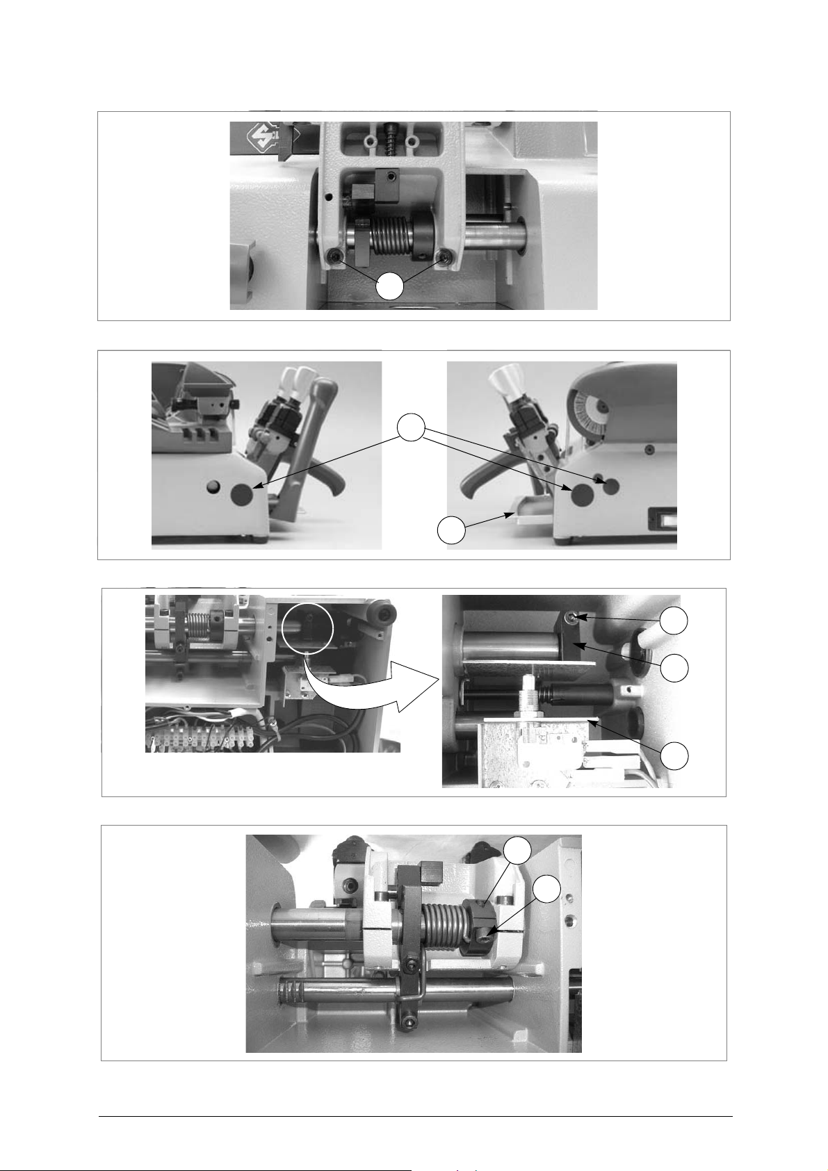
12)
Loosen the screw (N1) on the cam (N2) (fig. 50, page 32) and pull the cam to the right to remove
13)
Loosen the screw (Q1) on the spring ring nut (Q2)
14)
Push the carriage rod from right to left so that the spring can be removed
15)
Fit the new spring into its seat and push the carriage rod from left to right
16)Use a pivot to turn the ring nut (Q2), adjust spring tension and tighten the screw (Q1).
17)Take the carriage to the locked position (towards the operator).
18)Replace the cam (N2) so that it pushes the plate (N3) hard up against the microswitch; tighten the
screw (N1) (fig. 50, page 32).
19)Replace the bottom panel and fix with the 7 screws (W) and 2 feet. Fit the swarf tray.
20)Place the machine upright again (working position).
21)Fit the caps (D3).
22)Replace the carriage safety shield (D1) and fit the knob (V), pressing it downwards.
23)Tighten the 2 screws (V2).
24)Replace the protection from swarf (Z) and tighten the 2 scews (V1)
(N).
(fig. 49, page 32).
.
(V) (fig.47).
.
.
(fig. 48, page 32).
(W2) (ch.7.7, page 24).
(fig. 51, page 32).
.
. Tighten the 2 screws (D2).
).
.
Fig. 47
Copyright Silca 2011 31
Page 36
BRAVO MAXIMA II Operating manual - English
D2
D3
N
N2
N1
N3
Q2
Q1
Fig. 48
Fig. 49
Fig. 50
Fig. 51
32 Copyright Silca 2011
Page 37
Operating manual - English BRAVO MAXIMA II
X1
B4
X2
X3
B5
B6
-
+
NO! YES!
insulated points
with adhesive tape
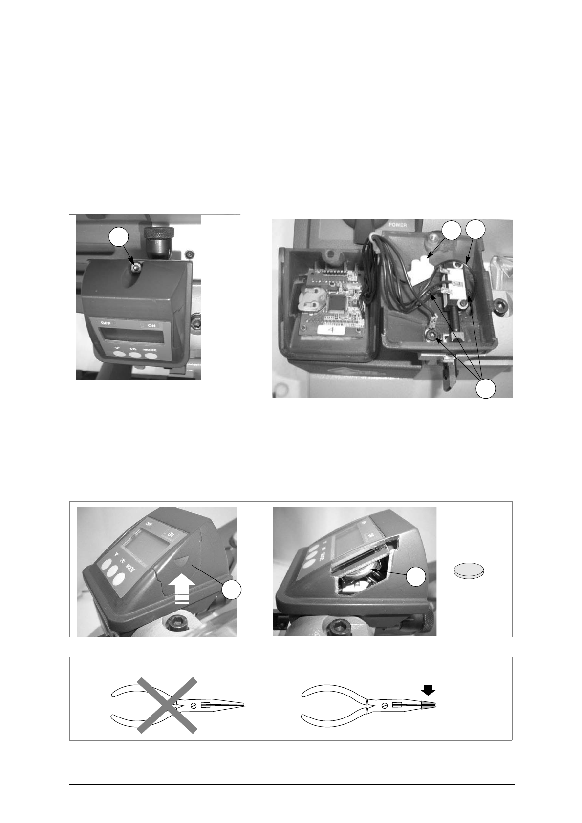
7.17 Replacing the Display unit
1) Turn the machine off and unplug it.
2) Loosen the screw (X1) and remove.
3) Pull the top part of the display out partially towards the front of the machine and raise.
4) Loosen the screw (X2) on the connector so that the wire (X3) is freed.
5) Loosen the 3 screws (B4) in order to remove the base of the display.
6) Fit the new display unit, first securing the new base with the 3 screws (B4), making sure you take the
wire (X3) through the special hole on the inside.
7) Replace the top part of the display, after connecting the wire (X3) to the connector, inserting it from
the front and pushing towards the back.
8) Tighten the screw (X1) to secure the top part of the display.
9) Check gauging with the electric contact (ch.5.11, page 14).
Fig. 52
7.18 Replacing the Display battery
1) Turn the machine off and unplug it.
2) Raise the side flap(B5) on the display assembly and remove.
3) Use a long-pronged pincer insulated with adhesive tape (fig.54) to remove the spent battery (B6).
4) Use long-pronged pincers with insulated points to fit the new battery, paying attention to the poles.
5) Replace the flap (B5) into its seat.
Fig. 53
Fig. 54
Copyright Silca 2011 33
Page 38

BRAVO MAXIMA II Operating manual - English
8 DISPOSAL
For correct disposal please refer to current standards.
INFORMATION FOR USERS OF PROFESSIONAL EQUIPMENT
From "Actuation of Directive 2012/19/EU regarding Waste Electrical and Electronic Equipment
(WEEE)"
The symbol of a crossed waste bin found on equipment or its packing indicates that at the end of the
product’s useful life it must be collected separately from other waste so that it can be properly treated
and recycled.
In particular, separate collection of this professional equipm ent when no longer in use is organised and
managed:
a) directly by the user when the equipment was placed on the market before 31 December 2010 and the
user personally decides to eliminate it without replacing it with new equivalent equipment designed for
the same use;
b) by the manufacturer, that is to say the subject which was the first to introdu ce and market new equip-
ment that replaces previous equipment, when the user decides to eliminate equipment placed on the
market before 31 December 2010 at the end of its useful life and replace it with an equivalent product
designed for the same use. In this latter case the user may ask the manufacturer to collect the existing
equipment;
c) by the manufacturer, that is to say the subject which was the first to introduce and market new equip-
ment that replaces previous equipment, if it was placed on the market after 31 December 2010;
With reference to portable batteries/accumulators, when such products are no longer in use the user
shall take them to suitable authorised waste treatment facilities.
Suitable separate collection for the purpose of forwarding discarded equipment and batteries/
accumulators for recycling, treatment or disposal in an environmentally friendly way helps to avoid
possible negative effects on the environmen t and human health and encourages re -use and/or recycling
of the materials making up the equipment.
To remove batteries/accumulators, consult the manufacturer’s specific instructions: (see relevant
chapter in the users’ manual)
The sanctions currently provided for by law shall apply to users who dispose of
equipment, batteries and accumulators in unauthorised ways
.
34 Copyright Silca 2011
Page 39

Operating manual - English BRAVO MAXIMA II
9 ASSISTANCE
Silca provides full assistance to purchasers of the BRAVO MAXIMA key-cutting machine.
To ensure complete safety for the operator, any job not specified in this manual should be carried out
by the manufacturer or in the special Service Centres recommended by Silca.
On the back cover of this manual is a list of the manufacturer’s addresses; listed below are the
addresses of specialised Service Centres.
9.1 How to request service
The guarantee attached to BRAVO MAXIMA key-cutting machines ensures free repairs or
replacements of faulty parts within 24 months of purchase. All other service calls must be arranged by
the customer with Silca or with a Silca service centre.
Note: the battery is not included in the guarantee.
Copyright Silca 2011 35
Page 40
VITTORIO VENETO 24/03/2011
CE DECLARATION OF MACHINE COMPLIANCE
SILCA S.p.A. - VIA PODGORA 20 ( Z.I.)
31029 VITTORIO VENETO (TV) - (ITALY)
TEL. 0438 9136 - FAX. 0438 913800
Declares under its own responsibility that the Key-cutting machine model
BRAVO MAXIMA
complies with the requirements of the following European Directives:
European Union DIRECTIVE 2006/42/CE (Machines)
and with the EN 292/1 – EN 292/2 Standards
European Union DIRECTIVE 2004/108/CE
and with the EN 55014-1:2000 + A1:2001 / EN 61000 – 3 – 2 :2000
EN 61000 – 3 – 3:1995 + A1:2001 Standards
European Union DIRECTIVE 2006/95/CE
and with the EN 60204-1 ( sections 20.2 – 20.3 – 20.4 ) Standards
Claudio Tomasella of the Silca S.p.A. Research & Development Division is authorized
to create a Technical File.
General Manager Basic Production Center
(Electromagnetic Compatibility)
(Low Voltage) | 03 |
Page 41
VITTORIO VENETO 24/03/2011
CE DECLARATION OF MACHINE COMPLIANCE
SILCA S.p.A. - VIA PODGORA 20 ( Z.I.)
31029 VITTORIO VENETO (TV) - (ITALY)
TEL. 0438 9136 - FAX. 0438 913800
Declares under its own responsibility that the Key-cutting machine model
BRAVO W - MAX
complies with the requirements of the following European Directives:
European Union DIRECTIVE 2006/42/CE (Machines)
and with the EN 292/1 – EN 292/2 Standards
European Union DIRECTIVE 2004/108/CE
and with the EN 55014-1:2000 + A1:2001 / EN 61000 – 3 – 2 :2000
EN 61000 – 3 – 3:1995 + A1:2001 Standards
(Electromagnetic Compatibility)
European Union DIRECTIVE 2006/95/CE
and with the EN 60204-1 ( sections 20.2 – 20.3 – 20.4 ) Standards
Claudio Tomasella of the Silca S.p.A. Research & Development Division is authorized
to create a Technical File.
General Manager Basic Production Center
(Low Voltage) | 03 |
Page 42

SILCA S.p.A.
Via Podgora, 20 (Z.I.)
31029 VITTORIO VENETO (TV)
Tel. 0438 9136 Fax 0438 913800
E-mail: [email protected]
www.silca.biz
Members of the Kaba Group
 Loading...