

silavent Green Line HRX2 Series, Green Line HRX2-S, Green Line HRX2-B, Green Line HRX2-FP, Green Line HRX2-BFP Installation And Operating Instructions Manual
LAB
939R, Issue 2, July 2014 Page 1
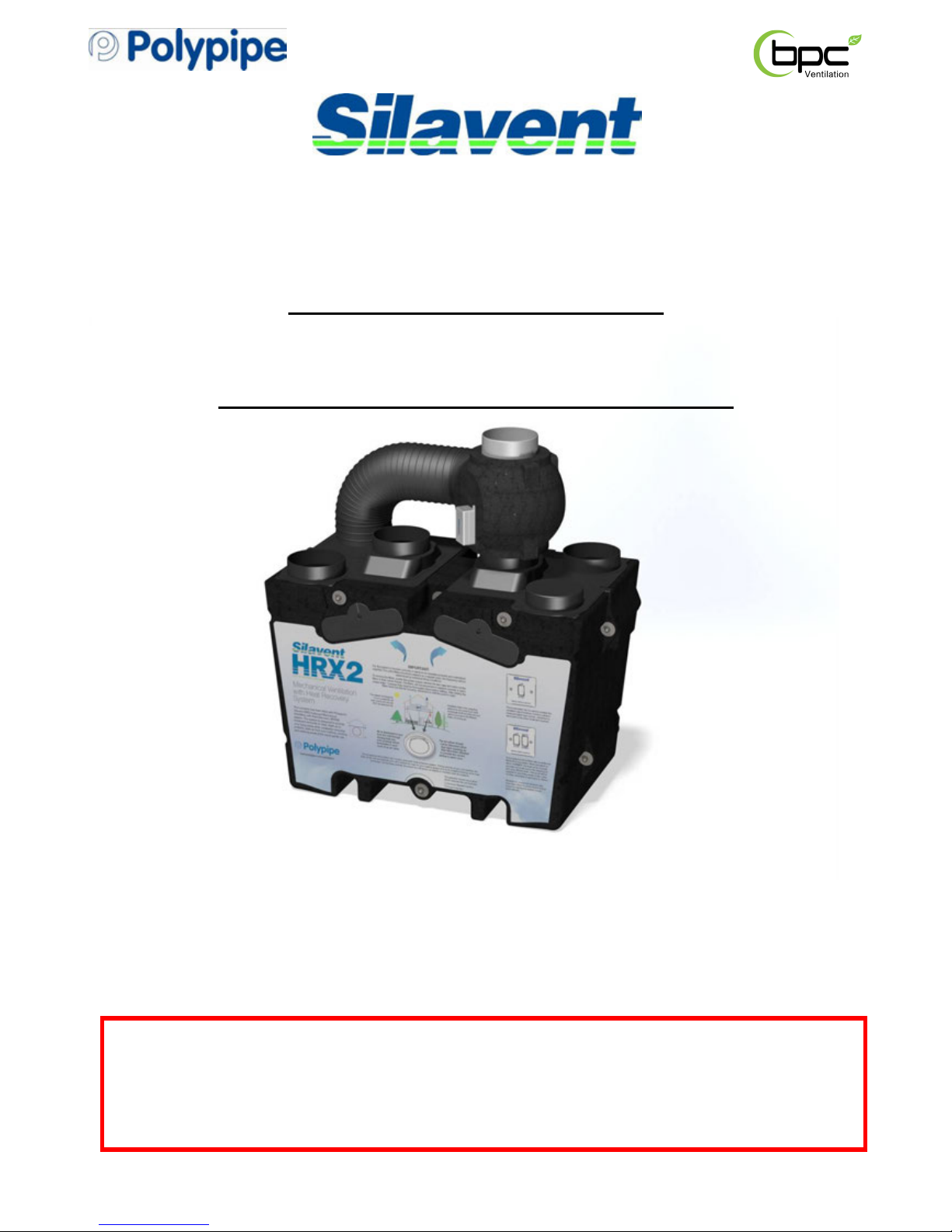
Green Line HRX2
Mechanical Ventilation with Heat Recovery appliance
Installation and Operating Instructions
Models: HRX2-S, HRX2-B, HRX2-FP, HRX2-BFP
These instructions must be given to the householder
DO NOT SWITCH OFF THE UNIT – it is designed to run continuously. If
the unit is switched off, indoor pollutants and moisture levels may
increase which could endanger your health or damage your home.
It is important to follow the advice in this manual and correctly maintain
the system to ensure a healthy indoor environment.
Have you considered an extended warranty package, for extra peace of
mind?
Polypipe offer extended warranty options. Please refer to page 22 for
further information or call 08443 715523.

LAB
939R, Issue 2, July 2014 Page 2
Warnings & Safety Information
IMPORTANT!
PLEASE READ THESE INSTRUCTIONS CAREFULLY BEFORE COMMENCING INSTALLATION
1. Do not install this appliance in areas where the following may be present or occur:
• Excessive oil or a grease laden atmosphere
• Corrosive or flammable gases, liquids or vapours
• Be subject to direct water spray
• Ambient temperatures higher than 50ºC and lower than -25ºC
• Possible obstructions that may hinder access or removal of the unit
2. This appliance is not intended for use by young children or infirm persons without adequate supervision.
3. All wiring must be in accordance with prevailing national regulations, for example the current IEE Wiring Regulations
BS7671. The electrical installation should be inspected and tested by a suitably qualified person after completion.
4. The appliance should be provided with a local double pole fused spur fitted with a 3Amp fuse and a minimum contact
separation of at least 3mm.
5. Ensure that the mains supply (Voltage and Frequency) complies with the rating label.
6. This appliance must be earthed.
7. When installing the appliance, care should be taken not to damage any hidden utilities.
8. The installer is responsible for the installation and electrical connection of the HRX2 system on site. It is the responsibility
of the installer to ensure that the equipment is safely and securely installed and left only when electrically and mechanically
safe.
9. All regulations and requirements must be strictly followed to prevent hazards to life and property, both during and after
installation and any subsequent servicing or maintenance.
10. In dwellings where it is intended to install open-flue appliances and extract ventilation, the combustion appliance should
be able to operate safely, whether or not the fans are running. A way of showing compliance with The Building Regulations
in these circumstances would be to follow the installation guidance shown below, and to show by tests that combustion
appliances operate safely, whether or not the fans are running.
A. For gas appliances: where a room contains an open-fl
ue appliance, the extract rate should not exceed
20l/s (72m³/h).
B. For oil appliances: where a room contains an open-flue appliance, the extract rate should be limited to
40l/s (144m³/h) for an appliance with a pressure jet burner and 20l/s (72m³/h) for an appliance with a
vaporising burner.
C. For solid fuel appliances: avoid installing extract ventilation in the same room.
Further reference should be made to Approved Document J of The Building Regulations.
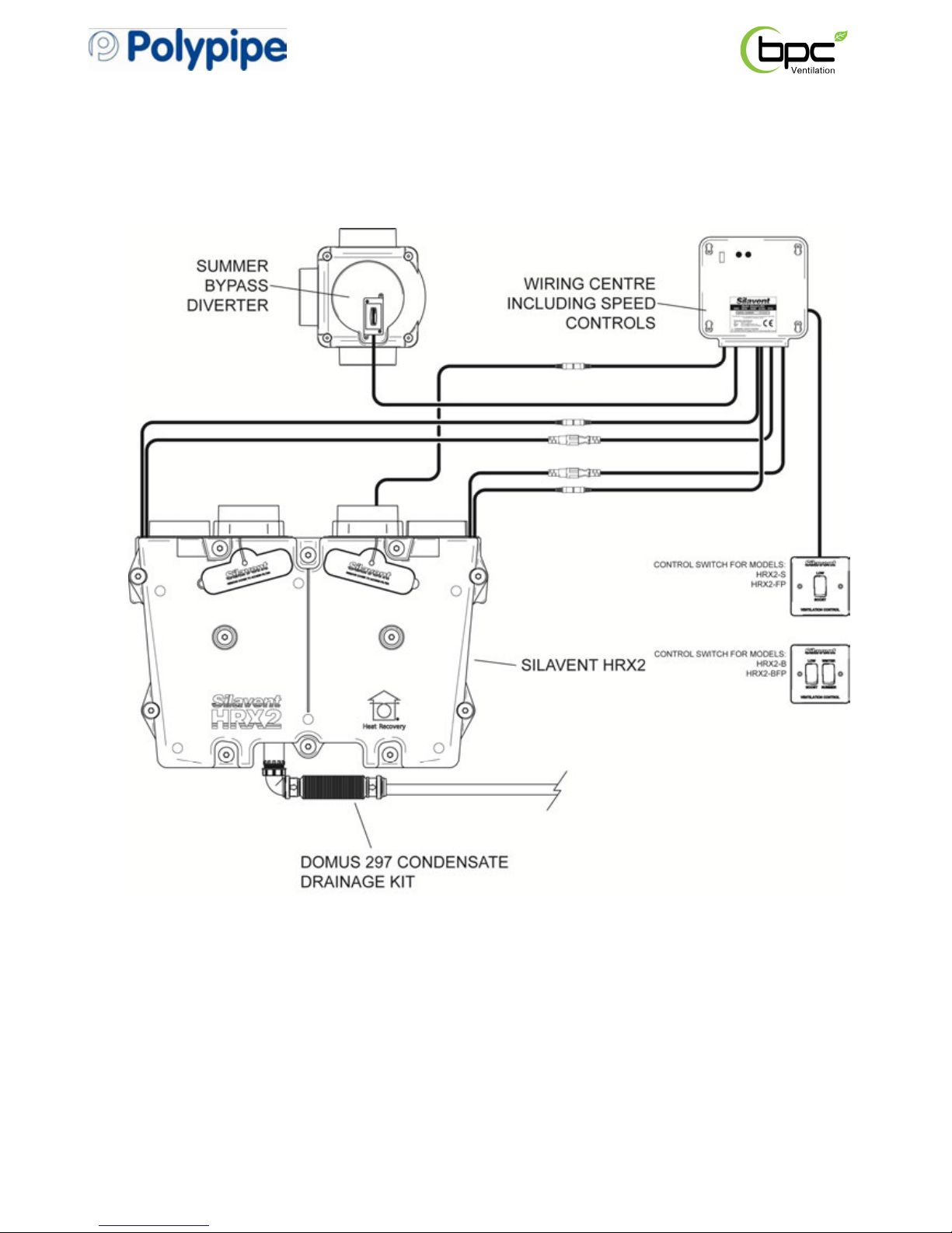
11. A condensate drain should be installed from the appliance to an appropriate drain location. Polypipe recommend
Domus 297 condensate drain kit.
12. The condensate drain and associated pipe work must be cleared of debris prior to commissioning and insulated where it
passes through unheated spaces and voids.
13. This appliance should not be connected to a tumble dryer or cooker hood.
14. The supply air must be drawn from the exterior of the property.
15. The extract air must be expelled to the exterior of the property.
16. It is recommended that the two external terminals or grilles are set at least 2m apart.
17. The supply and exhaust ceiling valves should be positioned at least 300mm from internal walls to allow airflow
measuring equipment to fit correctly over the valves.
18. Ducting should be insulated with Domus Thermal duct insulation where it passes through unheated spaces and voids
(e.g. loft spaces) to reduce the possibility of condensation forming and heat loss.

LAB
939R, Issue 2, July 2014 Page 3
Contents
Warnings & Safety Information
1.0 General description Page 4
1.1 Overview Page 4
1.2 Physical specification Page 6
1.3 Optional main features Page 6
1.3.1 Summer bypass Page 6
1.3.2 Frost protection Page 6
2.0 Installation Page 7
2.1 Overview Page 7
2.2 Preparation Page 7
2.3 Installing the frost protection sensor Page 9
2.4 Wall/surface fitting the HRX2 appliance Page 9
2.5 Fitting the bypass valve Page 10
2.6 Fitting the wiring centre Page 11
2.7 Fitting the condensate drain kit Page 12
2.8 Ducting guidelines Page 12
3.0 Electrical Page 14
3.1 Overview Page 14
3.2 Frost protection only, wiring-centre fan connections Page 14
4.0 Commissioning Page 15
4.1 Overview Page 15
4.2 System balancing Page 15
HRX2-S wiring diagram Page 16
HRX2-B wiring diagram Page 17
HRX2-FP wiring diagram Page 18
HRX2-BFP wiring diagram Page 19
ANC108A, ANC802A, ANC846A, ANC808A, ANC813A & ELE150R
wiring diagrams Page 20
5.0 Maintenance Page 21
5.1 Routine maintenance Page 21
6.0 Warranty Page 22

LAB
939R, Issue 2, July 2014 Page 4
1.0 General description (all models)
1.1 Overview
1.1.1 The Silavent HRX2 appliance is a key part of a whole house ventilation system specifically
designed to improve indoor air quality in dwellings. The system is designed to provide
measured amounts of filtered, fresh air to living areas while constantly removing polluted,
stale air from bathing, cooking and washing areas at the same gentle rate. Any available heat
in the outgoing stale air is recovered by a built-in heat exchanger and used to pre-warm the
fresh supply air.
1.1.2 A manual boost switch is provided to increase the ventilation rate, e.g. when cooking or
showering thereby maintaining a comfortable indoor environment.
1.1.3 The boost facility can also be triggered from a lighting circuit or by a range of sensors,
including humidity control and movement detection (supplied separately – see section 1.1.8)
1.1.4 The G3/EU3 filters in the appliance ensure that the fresh supply air is clean as it enters the
home. Additionally, the stale extract air is filtered to protect the heat exchanger from
unwanted contamination. These filters have to be cleaned regularly, depending on the levels
of pollution. The filters should be replaced when they start to show visible signs of wear.
1.1.5 This product is listed in SAP Appendix Q, therefore, part of the installation process requires
that an installation checklist is completed and submitted to the Building Control Body (BCB).
Blank checklists are available at www.sap-appendixq.org.uk
1.1.6 Pack includes:
• Silavent HRX2 appliance
• Two duct connection plates and a bag of 18 fixing screws.
• Wi
ring centre
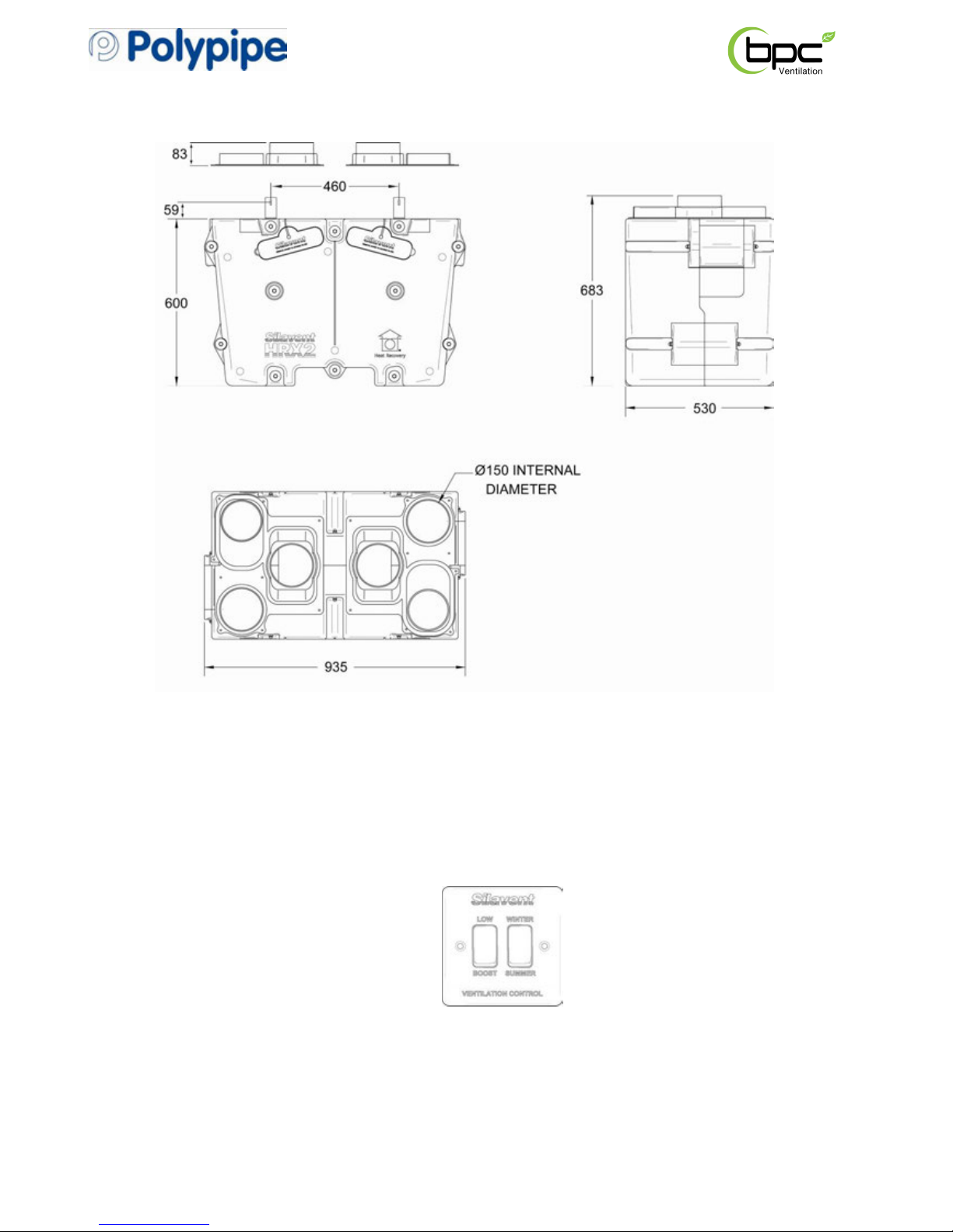
• Ventilation control switch - either one gang boost control (models HRX2-S, HRX2-FP) or two
gang combined boost and summer bypass control (models HRX2-B, HRX2-BFP)
• Installation and operating instructions manual and ‘householder-instruction cover’ with fixings
1.1.7 Ancillary items required:
• Domus Ø150mm rigid duct system (Domus 220mm x 90mm rectangular can be used in
restricted spaces), or Domus radial duct system (see 2.8)
• Optional Domus HRX2-CK1 ‘soft’ duct connection kit (see 2.8.3)
• Domus Thermal duct insulation (see 2.8.4)
• Domus 297 condensate drainage kit (see 2.7)
1.1.8 Ancillary options (see page 20)
• Silavent adjustable overrun timer, code ANC108A
• S
ilavent humidity control (with adjustable overrun timer), code ANC802A
• Silavent humidity control (with adjustable overrun timer and remote sensor), code ANC846A
• Silavent humidity control (with adjustable overrun timer and manual override with neon
indicator), code ANC808A
• Silavent PIR movement control (with adjustable overrun timer), code ANC813A
• Silavent 6-Switched live backfeed protected junction box, code ELE150R
LAB
939R, Issue 2, July 2014 Page 5
LAB
939R, Issue 2, July 2014 Page 6
1.2 Physical specification
net weight 20kg
1.3 Optional main features
1.3
.1 Summer bypass (HRX2-B, HRX2-BFP models)
The models listed above will be supplied with an additional Winter/Summer switch (see
highlighted option boxes on the appliance cardboard cover). When the switch is set to
summer, the fresh air is no longer pre-warmed by the heat in the outgoing stale air.
Important: when the switch is set to summer, both fans will stop for 45 seconds to allow the
bypass diverter valve to open.
1.3.2 Frost protection (HRX2-FP, HRX2-BFP models)
The models listed above are supplied with an automatic frost protection system. During
periods of very cold weather, the fresh air supply fan will automatically turn off to reduce the
load on your heating system and avoid possible freezing of the heat exchanger. During these
periods, the extract fan will speed up slightly to maintain an even air pressure. See also
section 2.3.
LAB
939R, Issue 2, July 2014 Page 7
2.0 Installation
2.1 Overview
2.1.1 The following instructions are intended to help prevent hazards. Installation should only be
carried out by a qualified electrician and competent persons in clean, dry conditions where
dust and humidity are at minimum levels.
Note: we advise installers to fix all mains, switch and sensor wiring (in accordance with the
latest edition of the Wiring Regulations) prior to fixing the HRX2 unit in position. For
convenience, buried cables for the wiring centre should terminate in a 2 gang metal box or
dry-lining box. The wiring centre can be fixed directly onto the box using standard M3.5
screws (not supplied).
2.2 Preparation
2.2.1 When accepting delivery of the appliance, inspect for transit damage. If in doubt, call our
Customer Services team on 08443 715523.
2.2.2 The HRX2 appliance and wiring centre can be fitted directly to a wall or suitable vertical or
horizontal timber support (if loft mounting). Important: if mounting on a horizontal surface,
make sure that adequate space/height has been considered for the condensate drain.
2.2.3 Ensure that the position chosen for the wiring centre is close enough to the HRX2 appliance
so that there is no undue strain applied to the cables between the HRX2 appliance and the
wiring centre. Important: these cables can not be lengthened or shortened.
2.2.4 Appropriate screw fixings to suit the support medium will need to be supplied by the installer.
The support brackets for vertical mounting are pre-drilled to suit 2 x 4mm (No.8) round/panhead screws.
2.2.5 Ensure that there is sufficient space for the wiring centre, condensation fittings and ductwork.
2.2.6 Ensure that there is sufficient space at the front of the appliance to access the filters and for
carrying out any future maintenance on the appliance.
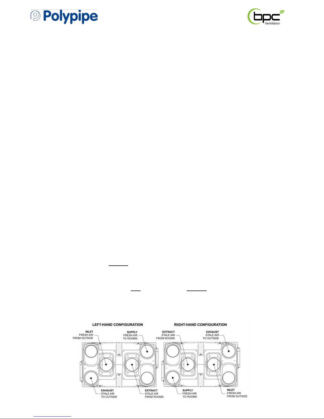
2.2.7 The HRX2 appliance can be mounted as a left-hand or right-hand installation, i.e. for
convenience the two external
duct connections can be either on the left or right-hand side.
This feature can be extremely useful in smaller houses or apartments where there is no space
to cross over ducts.
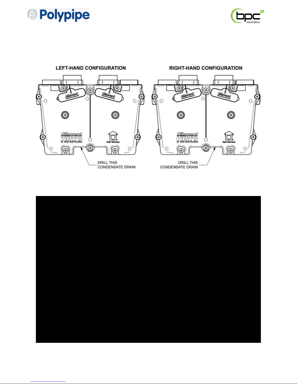
2.2.8 When viewed from above, the two duct configuration options are shown on the diagram
below:
IMPORTANT: The configuration selected will determine the connection point for the
condensate drain – see diagram below.
LAB
939R, Issue 2, July 2014 Page 8
2.2.9 Using a hole-saw of minimum diameter 20mm (3/4”) and maximum diameter 25mm (1”),
remove the closed end of the condensate tray ensuring that any debris is entirely removed.
For convenience a drill centring guide has been moulded into the tray – see diagram below.
 Loading...