

SIL B12-10C, C16-10, 107-10b, B12-10b Programming Manual
Minimum threshold or Low-level cut-off (% of FSD)
The percentage of full scale below which the output signal is cut-off
to zero. This is applicable only to successful measurements within
the period defined by the Static State Timeout.
Minimum: 0.1, Maximum: 100, Default: 1
Tip… This parameter is more suitable for measurements that
are typically well above 1Hz. As the sampling period is a
minimum of one second, it will take at least this time for
the output to clip to zero if such a measurement suddenly
stops.
NOTE: For correct functioning of the configuration software,
one place of decimal only may be entered.
Averaging count
Spurious input signals are attenuated by averaging the number of
input measurements specified by the Averaging Count. The
Averaging Count is the number of measurements used for
calculating the running average.
Minimum: 1 (no digital filtering), Maximum: 20, Default 5
Change threshold (%)
To enable a rapid response to a change in the input signal, the most
recent input measurement is continuously compared with the
running average. If the change in input is greater than that specified
by the Change Threshold parameter, the current averaging cycle is
abandoned and a new one started.
Minimum: 0 (no averaging), Maximum: 100, Default: 10
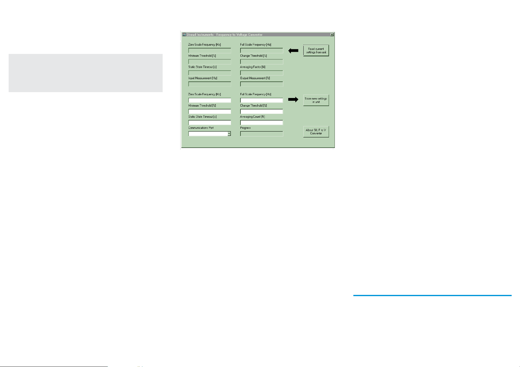
Input and output readings
With an input signal connected, the input measurement (Hz) and
output value (% of FSD) are displayed by the software.
NOTES:
(I) Storing or reading parameters will cause the current
measurement of the input signal to be abandoned. The
software will generate a warning if a new measurement has not
taken place since the last computer reading taken.
(ii) Parameter settings are restricted by the software to valid
limits. Notification is given by the software in the event of
range errors.
(iii) Fractional precision outside valid limits will be truncated on
downloading to the instrument.
(iv) A warning will be given by the software if the minimum
threshold setting corresponds to a time greater than the
combined static state timeout for high and low states.
(v) Measurements outside of defined input range are clipped to
limits with the exception of a 2.3% over-range which allows
measurements and outputs of up to 102.3% of full scale.
Troubleshooting
If no response is received from the F to A Converter, check the
following:
¨ The USB driver and programming software has been correctly
installed
¨ The Programme Protect Switch is set to the 'P' position.
¨ The correct COM port has been chosen.
¨ IR Link connections are secure.
¨ The F to A Converter is powered up.
¨ The IR Link Transceiver is positioned correctly.
¨ There are no other infrared sources which may temporarily
disrupt communications.
®
SIL
FREQUENCY TO ANALOGUE
CONVERTER
Programming Guide
For the following types B12-10C, C16-10 and
superceded types 107-10b and B12-10b
Document Ref: PGC16-10.vp Rev 2
STROUD INSTRUMENTS LTD.
36-40 Slad Road, Stroud, Glos. GL5 1QW, England
Telephone: +44 (0)1453 765433 Fax No: +44 (0)1453 764256
www.sil.co.uk

Frequency to analogue converter
configuration software
Minimum requirements
PROG-10U Programming Kit
PC with vacant USB port
The software is Windows™ 98/NT/ME/2000/XP, etc. compatible.
Install the USB Link IR virtual Com Port Driver
NB The driver should be installed before connecting the IR Link to the
PC.
1. Open the 'Freq_to_Analogue' folder on the CD.
2. Open the 'USB-LINK-IR' folder.
3. Double-click 'USB-LINK-IR.exe' to install.
4. Follow the on-screen instructions to complete the
installation.
5. Note: when installing on Windows 7 an update to the
'CP2102 USB to UART Bridge Controller' will be required. Win 7
normally searches for and installs this update automatically.
Should it fail to do so the driver update is provided on the CD in
the USB to UART Bridge Controller Update folder. The
'Read_Me_First' file on the CD also provides a link to the update
download page.
Install the configuration software
1. Open the 'Freq_to_Analogue' folder on the CD.
2. Double-click the 'F-to-A-Config' folder.
3. Double-click 'setup.exe' to install
NOTE: Software may be downloaded from
www.sil.co.uk/software.htm
Programme protect switch
To improve noise immunity in areas near to variable speed drives,
switch gear or other sources of strong magnetic fields, the F to A
Converter is supplied with a Programme Protect Switch: position ‘R’
(Run) is for normal operational mode and position ‘P’ for
programming the unit. The switch is located on the front of the
instrument. Please note: the Programme Protect Switch must be
returned to the 'R' position after programming. With the switch in
position 'P' the output is held at the zero value.
Positioning the IR transceiver
Infrared communications are effective at distances up to one metre.
The IR USB Link Transceiver must be pointed at the two infrared
transceiver windows, located on the front panel above the
Programme Protect Switch. The IR Link Transceiver has a beam angle
IR Link
of approximately 15
sight must be unobstructed.
NOTE: If there are other C16-10, B12-10 or 107-10B units in the
vicinity, ensure they are 'programme protected' i.e. by link - on
107-10b & B12-10b units, by switch on the B12-10C or C16-10
units, or otherwise shielded from the infrared beam.
o
so alignment is not critical however the line of
Setting up the IR link
Before communication with the F to A Converter can be initiated,
the software must be configured for the appropriate serial (COM)
port. Open the F to A Converter programmer application and select
the appropriate COM port from the ‘Communications Port’ drop
down list (bottom left hand of the application window).
Confirm communication with the F to A Converter has been
established by clicking the “Read current settings from unit” button.
Refer to ‘Troubleshooting’ if no reply is received from the unit.
Programming
Settings are stored in non-volatile memory. To obtain the settings
currently programmed into the F to A Converter, click the
'Read current settings from unit' button.
How digital filtering works
Digital filtering enables effective attenuation of noise yet permits a
rapid response to a change in the input signal.
Spurious input signals are attenuated by averaging a series of input
measurements. The number of measurements used in the averaging
process is specified by the ‘Averaging Count’ parameter.
When this is set to a count of ‘1’, no digital filtering is performed.
Increasing the Averaging Count will increase the amount of input
signal filtering but will incur a proportionate increase in response
time.
To enable a rapid response to a change in the input signal, the most
recent input measurement is continuously compared with the
current average. If the change is greater than that specified by the
‘Change Threshold’ parameter (this is specified as a percentage of
FSD), the current averaging cycle is abandoned and a new one
started.
The characteristics of the digital filter can therefore be modified by
the Change Threshold and Averaging Count parameters. Changes in
input due to noise or spurious signals that do not exceed the Change
Threshold will be filtered therefore increasing the Change Threshold
increases the maximum change in input that can be filtered.
Increasing the Averaging Count will increase the attenuation of these
spurious signals.
The response time for the output of the F to A Converter to settle
will depend on the number of readings specified by the Averaging
Count. Consequently a large value of Change Threshold will result in
slow response times for all but large changes in input.
Tip… The Change Threshold should be set to the lowest setting
that gives adequate noise rejection whilst providing
satisfactory response times for the application.
With the Change Threshold set low, the value of the Averaging
Count will not affect the response time for a step input change but
if the input is changing very slowly, a large value of Averaging Count
will cause the output signal to lag behind the input.
Tip… The Averaging Count should be set to the lowest value that
gives sufficient filtering.
Programmable parameters
Output scaling
The output signal may be scaled to any portion of the input signal
frequency range with the following parameters.
NOTE: For correct functioning of the configuration software,
two places of decimal only may be entered for the following
frequency settings.
1- Zero Scale Frequency (Hz)
The input signal frequency giving zero output signal.
Minimum: 0, Maximum: 5000, Default: 0
2- Full Scale Frequency (Hz)
The input signal frequency giving full scale output signal.
Minimum: 0.1, Maximum: 5000, Default: 1000
Static state timeout (seconds)
If the period in which the input signal remains unchanged exceeds
this value, the current measurement is abandoned and the output
signal cut to zero. In the event of a transducer or signal line failure,
this facility ensures the output is not erroneously held at the last
reading. The maximum allows for valid measurements to be taken
with a single pulse every 4000 seconds i.e. f=0.00025Hz.
NOTE: This parameter overrides ‘Minimum Threshold'.
Minimum: 2, Maximum: 4000, Default: 2
 Loading...