

Page 1

MULTIPLIER
Type 107-12A
User Guide
Doc ref ud107-12a.vp Rev 3
Page 2
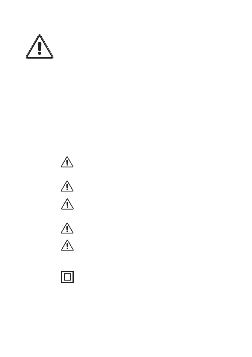
WARNING!
It is important that this guide is read and fully understood before
attempting installation or commissioning of the instrument.
Instructions appearing in this document, and current safety
legislation, must be observed to ensure personal safety and to
prevent damage to the instrument or equipment connected to it.
The instrument should be installed, commissioned and operated
only by suitably qualified and authorised personnel.
Safety and EMC information
Safety: EN61010 -1
Immunity: EN50082-1
Emissions: EN50081-1
CE certified
The specifications for the instrument must not be exceeded. If
the instrument is used in a manner not specified, the
protection provided by the instrument may be compromised.
The instrument must be installed in an enclosure that provides
adequate protection against electric shock.
Ensure that power to the instrument is switched off and signal
wiring isolated from hazardous voltages before carrying out
installation or maintenance.
The instrument is designed for installation in a clean, dry
environment (Pollution degree 1).
Stroud Instruments Ltd strongly recommends that repairs and
re-calibration work are done on a return to factory basis in
order that our quality standards, product specifications and
safety precautions are not compromised.
The instrument is double insulated
Note: Clean with a moist cloth - USE NO SOLVENTS.
Page 1
Page 3

Installation
WARNING: Installation should be
conducted by appropriately skilled and
authorised personnel only.
WARNING: Ensure that power to the
instrument is switched off and signal
wiring isolated from hazardous voltages
before carrying out installation.
WARNING: The instrument must be
installed in an enclosure that provides
adequate protection against electric shock.
Location
¨ The instrument is designed for
installation in a clean, dry environment
¨ Do not install near to switch gear,
motor controllers or other sources of
strong magnetic fields.
¨ Avoid exposure to direct sunlight and
ensure the ambient temperature inside
the enclosure that the unit is mounted
in will not exceed our specification.
Plug in Module
Retaining Screws
Optional DIN Clip
Dimensions in mm
Module height 95mm, units with dial 117mm
Fixing
107 Series Modules are designed to be
fitted to any flat dry surface using two
4mm screws. Alternatively, by fitting an
optional DIN clip, they may be clipped to
a rail conforming to BS5584:1978,
EN50 022, DIN46277-3.
Grommets are provided on three sides of
the base section and there are two rear
entry knock outs in the bottom.
Page 2
Page 4
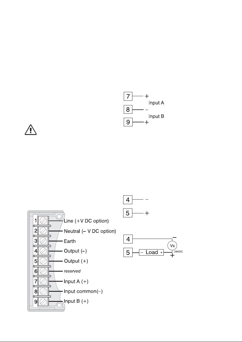
Wiring and connections
Segregate power supply and signal
¨
wiring.
Use screened cable for all signal wiring
¨
with the screen earthed at instrument
end only.
All connections should be made using
¨
ferrules.
Screw terminals are provided - wire
capacity 2 x 1.5mm
2
Access to Terminals
WARNING: Ensure that power to the
instrument is switched off and signal
wiring isolated from hazardous voltages
Loosen the two module securing screws.
Gently pull away the top section of the
module from its base to expose the fixing
points and wiring terminals. To refit the
module, align the module edge
connectors with the socket in the base
and carefully press home. NB do not
over tighten the module securing screws.
Input connections
Inputs are configured during manufacture
to suit the application specified. A change
in the type of input from voltage to current
or vice versa will require a return to factory
for re-configuration.
Voltage and mA
Output connections
Outputs are configured during
manufacture to suit the application
specified. A change in the type of output
will require a return to factory for
re-configuration.
Voltage and current
Current sink
Page 3
External
voltage
source
Page 5
Power supply connections
This instrument is supplied in one of two
power supply versions.
a.1. AC mains supply: 110, 200, 220 or
240 VAC ±10% 50/60Hz; 5VA
b.2. DC supply: 12, 24 or 48V -10% to
+20%; 3.5W
WARNING: Check that the supply voltage
on the data label (on side of instrument) is
suitable for the application.
WARNING: Ferrules must be used for AC
mains power wiring
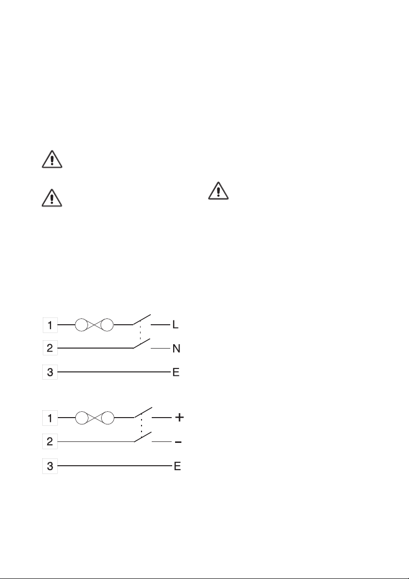
Power supply wiring to the instrument
should be protected by a suitable fuse
and double pole switch - see below. The
switch should be clearly marked as the
isolating switch for the instrument.
AC Mains
Please note:
The unit cannot be changed by the user
from one type of power supply version to
another. This conversion can only be
done on a return to factory basis.
Fuse replacement and
supply voltage
adjustments
Gaining access to power supply
WARNING: Switch off all supplies and
isolate signal and other wiring from
dangerous voltages before proceeding.
(i) Remove plug-in module as described
in Access to Terminals in the
Installation section.
(ii) The plate with the terminal
connections label can now be
removed by easing apart the longer
sides of the module to release the
interlocking tongue and groove.
(iii) Note the location of the printed circuit
board which must be replaced in the
same position. Slide out the board.
DC supply
Page 4
Page 6
Changing AC supply voltage
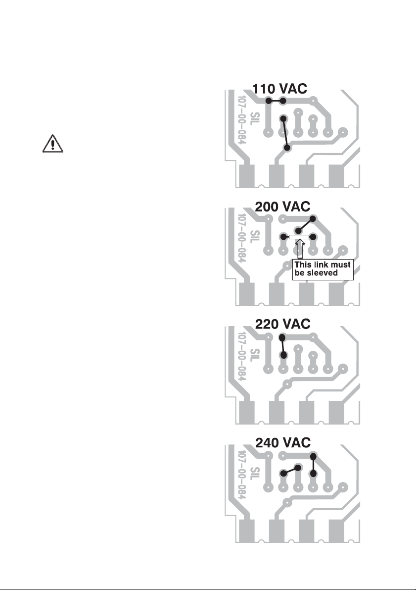
Mains powered units can be adapted for
operation on 110V, 200V, 220V or 240V
supplies. Fig 1 provides details of the
required link settings which are effected
by soldered tinned copper wire links.
WARNING: Links for 200V operation
must be insulated with silicon rubber
sleeving.
DC powered versions
The operating supply voltage on DC
powered units cannot be changed by the
user. This conversion can only be done
on a return to factory basis.
Fuse replacement
The fuse holder is located at the edge of
the circuit board and above the mains
transformer or DC power unit.
Fuse size: 20mm x 5mm dia.
Fuse ratings:
AC Supply - 100mA Quick Blow
12V/24V DC - 250mA Anti-surge
48V DC -100mA Anti-surge
Fig. 1 AC mains supply links
Re-assembly
Re-check your link selections.
Replace the printed circuit board into the
case ensuring that it is located in the slot
under the LED indicator window. Replace
the bottom plate by first engaging the
side with the two tongues into the slots in
the case and then press the plate home
to engage the side with the single tongue.
Plug the reassembled module into the
base section and secure with the two
captive screws provided - do not
overtighten.
Page 5
Page 7

SPECIFICATION
INPUTS
0-10 mA into 100 ohms
0-20 mA into 50 ohms
4-20 mA into 62.5 ohms
0-5v into greater than 1 M ohms
1-5v into greater than 1 M ohms
OUTPUTS
0-10 mA into 2000 (5000) ohms max
0-20 mA into 1000 (2500) ohms max
4-20 mA into 1000 (2500) ohms max
0-5v into 500 ohms min
1-5v into 500 ohms min
Current Sink 4-20mA @ 50 Volts max.
FUNCTION
Output = (A + a) (B + b) x k + c, where A and B
are inputs and a, b, c and k are constants.
CALIBRATED ACCURACY
Set at 100% to be within ± 0.2% FSD.
LINEARITY ERROR
≤ ± 0.4% FSD.
SUPPRESSION/ELEVATION ERROR
≤ ± 0.1% FSD.
OUTPUT RIPPLE
≤ 0.1% (Peak to Peak) of FSD.
LOAD RESISTANCE EFFECT
≤ 0.001% of span/100 ohms change.
ISOLATION
The inputs and output are not isolated from each
other, but are isolated from the power supply.
STABILITY
Over 24 hrs ± 0.05% FSD.
Over 1 year ± 0.1% FSD.
INTERFERENCE REJECTION
Filtering is incorporated to reject R.F. and
other industrial noise.
SERIES MODE REJECTION
< 0.2% error for 50 Hz RMS
Signal equal to 50% span
figures in
⎫
brackets
⎬
⎭
are options
INPUT OVER-RANGE PROTECTION
250 volts RMS or DC (voltage inputs only)
TEMPERATURE COEFFICIENTS
Zero: ± 0.02% span/°C
Span: ± 0.02% span/°C
TEMPERATURE RANGE
Operating: -10°C to + 60°C
Storage: -20°C to + 70°C
SUPPLY VOLTAGE REJECTION
Output change < 0.01% span/% supply change.
POWER SUPPLY
AC versions: 110, 220, 240V ± 10%
50/60Hz 5VA
Fuse (internal) 100mA quick-blow (20 x 5mm)
DC versions: 12, 24, 48V -10% +20% 3.5W
Fuse (internal) 250mA anti-surge (20 x 5mm)
ENCLOSURE DETAILS
Base: Phenol (black)
Cover: Polystyrol (light grey)
Protection: IP40
SAFETY & EMC
Safety: EN61010-1 Immunity: EN50082-1
Emissions: EN50081-1 CE certified
WEIGHT
Approximately 0.5 kg
Continuous development may necessitate changes in these details without notice.
Page 6
 Loading...