

USER'S MANUAL
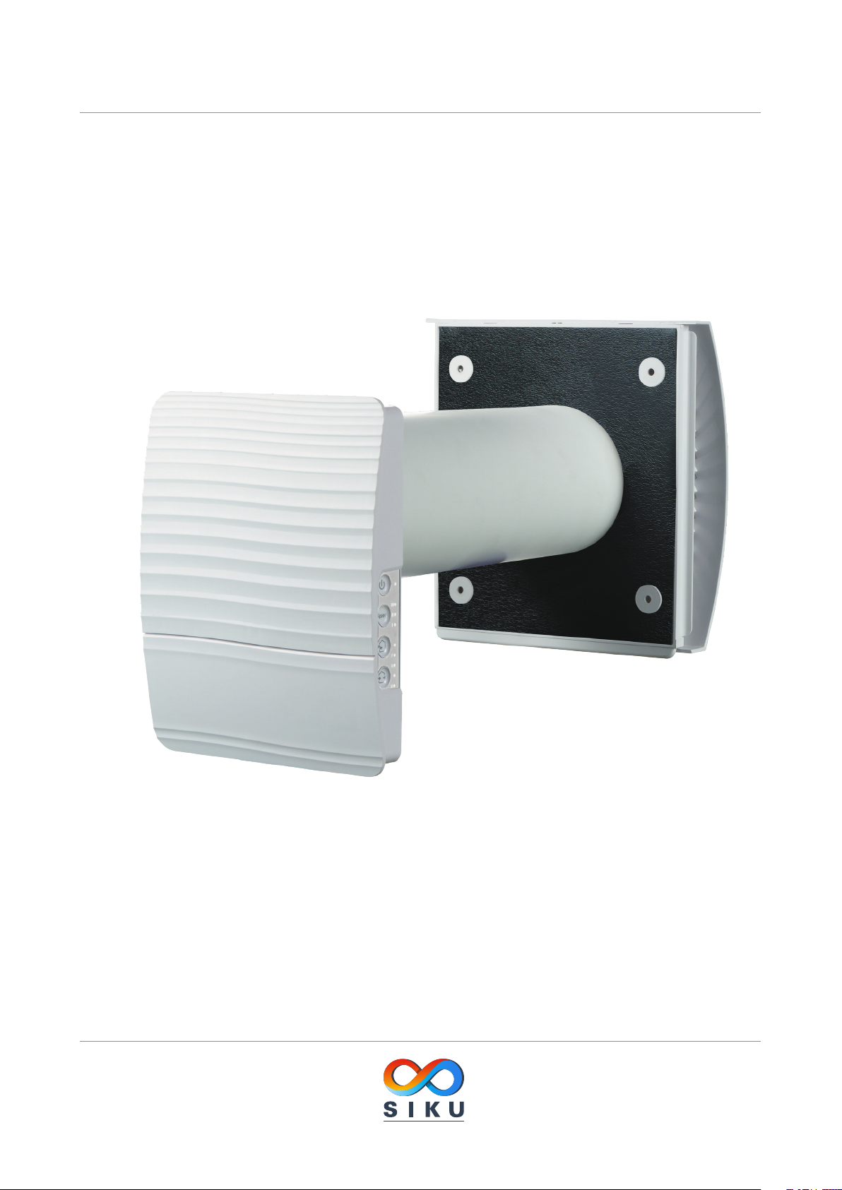
SIKU RV 25 W Pro WiFi V2
Single-room reversible energy regeneration ventilator

SIKU RV 25 W Pro WiFi V2
CONTENTS
Safety requirements .....................................................................................................................................................................2
Purpose ................................................................................................................................................................................................4
Delivery set ........................................................................................................................................................................................ 4
Designation key .............................................................................................................................................................................. 4
Technical data .................................................................................................................................................................................. 5
Unit design and operating principle ................................................................................................................................. 6
Installation and set-up................................................................................................................................................................ 7
Connection to power mains and control .......................................................................................................................10
Technical maintenance .............................................................................................................................................................. 21
Troubleshooting ............................................................................................................................................................................. 22
Storage and transportation regulations .......................................................................................................................... 22
Manufacturer’s warranty ........................................................................................................................................................... 23
Certificate of acceptance .......................................................................................................................................................... 27
Seller information .......................................................................................................................................................................... 27
Installation certificate .................................................................................................................................................................. 27
This user’s manual is a main operating document intended for technical, maintenance, and operating staff. The manual contains
information about purpose, technical details, operating principle, design, and installation of the SIKU RV 25 W Pro WiFi V2 unit and all its
modifications.
Technical and maintenance staff must have theoretical and practical training in the field of ventilation systems and should be able to
perform works in accordance with workplace safety rules as well as construction norms and standards applicable in the territory of the
country.
The information in this user’s manual is correct at the time of the document’s preparation.
The Company reserves the right to modify the technical characteristics, design, or configuration of its products at any time in order to
incorporate the latest technological developments.
No part of this publication may be reproduced, stored in a retrieval system, or transmitted, in any form or by any means in any information
search system or translated into any language in any form without the prior written permission of the Company.
SAFETY REQUIREMENTS
• Please read the user’s manual carefully prior to installing and operating the unit.
• All user’s manual requirements as well as the provisions of all the applicable local and national construction, electrical, and technical
norms and standards must be observed when installing and operating the unit.
• The warnings contained in the user’s manual must be considered most seriously since they contain vital personal safety information.
• Failure to follow the rules and safety precautions noted in this user’s manual may result in an injury or unit damage.
• After a careful reading of the manual, keep it for the entire service life of the unit.
• While transferring the unit control, the user’s manual must be turned over to the receiving operator.
UNIT INSTALLATION AND OPERATION SAFETY PRECAUTIONS
• Disconnect the unit from power mains prior
to any installation operations.
• The unit must be grounded!
• Unpack the unit with care.
• While installing the unit, follow the safety
regulations specific to the use of electric
tools.
2
www.siku.cc
SIKU RV 25 W Pro WiFi V2
• Do not change the power cable length at
• Do not use damaged equipment or cables
your own discretion. Do not bend the power
cable. Avoid damaging the power cable. Do
not put any foreign objects on the power
cable.
when connecting the unit to power mains.
• Do not lay the power cable of the unit in
close proximity to heating equipment.
• Do not operate the unit outside the
temperature range stated in the user’s
manual. Do not operate the unit in
aggressive or explosive environments.
• Do not touch the unit controls with wet
hands. Do not carry out the installation and
maintenance operations with wet hands.
• Do not allow children to operate the unit.
• Do not store any explosive or highly
flammable substances in close proximity to
the unit.
• Do not open the unit during operation.
• Do not block the air duct when the unit is
switched on.
• Do not wash the unit with water. Protect the
electric parts of the unit against ingress of
water.
• Disconnect the unit from power mains prior
to any technical maintenance.
• When the unit generates unusual sounds,
odour, or emits smoke, disconnect it from
power supply and contact the Seller.
• Do not direct the air flow produced by the
unit towards open flame or ignition sources.
• In case of continuous operation of the unit,
periodically check the security of mounting.
www.siku.cc
• Do not sit on the unit and avoid placing
foreign objects on it.
THE PRODUCT MUST BE DISPOSED SEPARATELY AT THE END OF ITS SERVICE LIFE.
DO NOT DISPOSE THE UNIT AS UNSORTED DOMESTIC WASTE.
• Use the unit only for its intended purpose.
3

SIKU RV 25 W Pro WiFi V2
PURPOSE
The ventilator is designed to ensure continuous mechanical air exchange in flats, cottages, hotels, cafés and other domestic and public
premises. The ventilator is equipped with a regenerator that enables supply of fresh filtered air heated by means of extract air heat energy
recovery. The ventilator is designed for wall flush mounting.
The unit is rated for continuous operation.
THE UNIT SHOULD NOT BE OPERATED BY CHILDREN OR PERSONS WITH REDUCED
PHYSICAL, MENTAL, OR SENSORY CAPACITIES, OR THOSE WITHOUT
THE APPROPRIATE TRAINING.
THE UNIT MUST BE INSTALLED AND CONNECTED ONLY BY PROPERLY QUALIFIED
PERSONNEL AFTER THE APPROPRIATE BRIEFING.
THE CHOICE OF UNIT INSTALLATION LOCATION MUST PREVENT UNAUTHORIZED
ACCESS BY UNATTENDED CHILDREN.
Transported air must not contain any flammable or explosive mixtures, evaporation of chemicals, sticky substances, fibrous materials,
coarse dust, soot and oil particles or environments favourable for the formation of hazardous substances (toxic substances, dust,
pathogenic germs).
DELIVERY SET
Name Quantity
Indoor unit 1 pc.
Air duct 1 pc.
Sound absorbing mat 1 pc.
Assembled cartridge 1 pc.
Outer ventilation hood 1 pc.
Cardboard mounting template 2 pc.
Fastening kit 2 sets
Polystyrene wedges 1 set
User's manual 1 pc.
Installation instruction for the ventilation hood 1 pc.
Packing box 1 pc.
4
www.siku.cc

SIKU RV 25 W Pro WiFi V2
TECHNISCHE DATEN
The unit is designed for indoor application at outdoor air temperatures from -15 ˚C (5 °F) up to +40°C (104 °F) and relative indoor humidity
up to 50 %.
The unit has Class II of protection against electric shock and must not be grounded.
Hazardous parts access and water ingress protection rating is IP24.
The unit design is constantly being improved, so some models may be slightly different from those ones described in this manual.
TECHNICAL DATA
Speed I II
Power supply voltage 50 (60) Hz [V] 1~100-240
Power consumption [W] 1.8 3.0 4.40
Current consumption [A] 0.027 0.037 0.051
Max. air flow [m3/h] (CFM) 10 (6) 20 (12) 30 (18)
Filters G3 (MERV 7);
Sound pressure level @ 1 m [dBA(Sones)] 30 (1.1) 37 (2.0) 40 (2.5)
Sound pressure level @ 3 m [dBA(Sones)] 21 (0.4) 28 (0.9) 31 (1.1)
Outdoor noise level attenuation [dBA (Sones)] 42 (2.5)
IP rating IP24
WIFI TECHNICAL DATA
Standard IEEE 802.11 b/g/n
Frequency band [GHz] 2.4
Transmission power [mW] (dBm) 100 (+20)
Power mains DHCP
WLAN safety WPA. WPA2
III
222
Länge des Lüftungsrohres
Air duct length
ø102,6
Außenhaube
ventilation
Außenabdeckung
Front panel
ø106,6
Outer
hood
The air duct length depends on the ventilator model, refer to the Designation
Key, page 4.
The supplied ventilation hood model depends on the ventilator model.
The distance A is 0-10 mm.
A
The overall dimensions of the front panel are stated below.
OVERALL DIMENSIONS OF THE INDOOR UNIT MM
189
123
www.siku.cc
175
39 55
140
5
SIKU RV 25 W Pro WiFi V2
die das Lüftungsrohr bei Abschalten der Lüftungsanlage schließt.
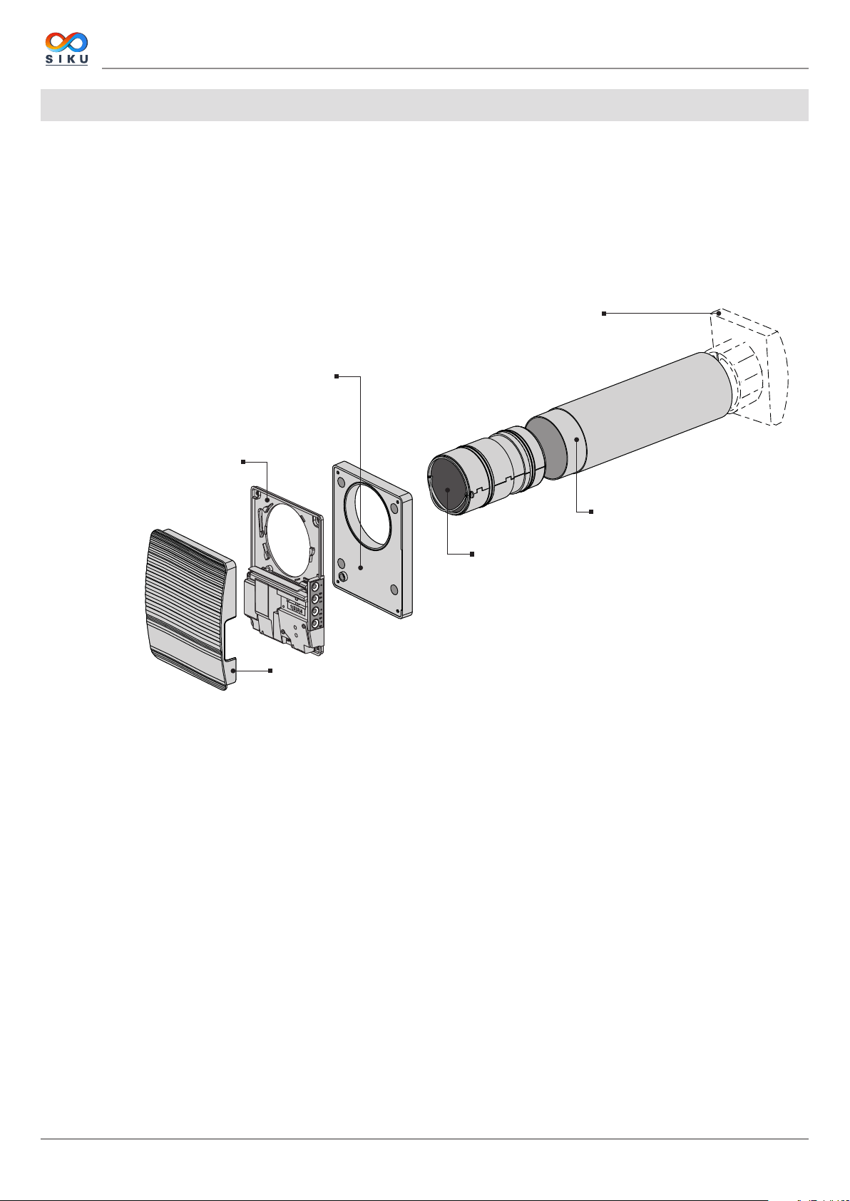
UNIT DESIGN AND OPERATING PRINCIPLE
The ventilator consists of an indoor unit with a decorative front panel, a cartridge, an air duct with a sound absorbing mat and an outer
ventilation hood.
Cartridge is the basic functioning part of the ventilator. The cartridge consists of a fan, a regenerator and two filters that ensure rough air
filtration and prevent ingress of dust and foreign objects into the regenerator and the fan.
The indoor unit is equipped with an automatic air damper that closes during shutdown of the ventilator and prevents air backdraft.
VENTILATOR DESIGN
Outer ventilation hood
Außenhaube
Each ventilator model has a matching ventilation hood model.
Wasser und Fremdkörpern von außen. Zu jedem Modell der
Mounting frame
Facilitates mounting of the ventilator in thin walls with the
Erleichtert die Montage der Lüftungsanlage in der dünnen
Wänden mit einer Dicke ab 135 mm.
Montagerahmen
thickness from 135 mm.
Protects the unit from ingress of water and foreign objects.
Schützt die Lüftungsanlage gegen Eindringen von
Lüftungsanlage gibt es eine passende Außenhaube.
Rückseite des Innenelementes
The unit includes a circuit control board
eine Steuerplatine und Sensor-Tasten.
Indoor unit rear side
Die Einheit umfasst
and touch buttons.
Cartridge
Patrone
Assembly unit consisting of a fan, a regenerator and air filters.
Einheit bestehend aus einem Ventilator, einem Wärmetauscher und
Generates air flow, provides energy regeneration and air cleaning.
Filtern. Erzeugt den Luftstrom und sorgt für die
Wärmerückgewinnung und Luftfiltration.
Indoor unit front panel
Außenabdeckung des Innenelementes
Equipped with an automatic air damper that closes up the air duct at
Mit einer automatischen Luftklappe versehen,
the ventilator power off.
Telescopic air duct
Teleskop-Lüftungsrohr
Plastic air duct.
Kunststoff-Luftleitung.
VENTILATOR OPERATION MODES
The ventilator has three operation modes:
Ventilation: the ventilator runs either in extract or supply mode at a set speed.
Air supply (available from a mobile device only): all the connected ventilators in the network go to the air supply mode.
Regeneration: the ventilator runs in the reversible mode with heat and humidity recovery.
In the Regeneration mode the ventilator operates in two cycles.
Cycle I. Warm stale extract air flows through the ceramic regenerator and heats it up and moisturizes the regenerator.
Cycle II. Fresh and cold intake air from outside flows through the ceramic regenerator, absorbs accumulated moisture and get heated up
to the room temperature with the heat accumulated in the heat exchanger.
6
www.siku.cc

SIKU RV 25 W Pro WiFi V2
A
A
The cover is
Die Abdeckung
closed
ist geschlossen
FUNCTIONING OF AUTOMATIC AIR DAMPER
The cover is
Die Abdeckung ist
open
geönet
The indoor unit has a front panel with automatic air damper. During the
ventilator operation the air damper opens to let the air flow through
the ventilator.
The air damper closes within 2 minutes after power off of the ventilator.
INSTALLATION AND SETUP
READ THE USER'S MANUAL BEFORE INSTALLING THE UNIT.
DO NOT BLOCK THE AIR DUCT OF THE INSTALLED VENTILATOR WITH DUST
ACCUMULATING MATERIALS, SUCH AS CURTAINS, CLOTH SHUTTERS, ETC.
AS IT PREVENTS AIR CIRCULATION IN THE ROOM.
1. Prepare a round core hole in the outer wall. The hole size is shown in the figure below.
A-A
"
16
min 500
min 19
/
11
min 500
min 19
11
/16"
min 500
min 19
ø 120
3
ø 4
11
/16"
/4"
2. Insert the air duct in the wall hole. For ease of installation use the polystyrene wedges included in the delivery set. The air duct end must
protrude for the distance A that enables installation of the outer ventilation hood. The distance A is 0-10 mm.
Polystyrolkeil
Polystyrene wedge
Füllen Sie die Hohlräume
Fill the gaps between the
zwischen dem Lüftungsrohr und
air duct and the hole with
der Wandöffnung mit
mounting foam.
Montageschaum aus.
ø106,6*ø102,6
min 3 mm
Install the air duct with the minimum slope of 3 mm downwards to
the outer wall side.
To cut the air duct either make preliminary calculations of the
required duct length or make sure to have access to the outer wall
after fixation of the air duct.
www.siku.cc
A
7

SIKU RV 25 W Pro WiFi V2
3. Take the required mounting template and then fasten it to the indoor wall using the adhesive tape. The large opening in the template
must be coaxial with the air duct. For aligning the template with respect to the horizon line it is recommended to use a builder’s level.
Then mark the fastening holes for installation of the supplied dowels and drill the holes to a required depth.
Route the power cable of the ventilator from the wall through the marked opening on the template.
Schablone zur Montage der
Mounting template for installation
Rückseite des Innenelements
of the rear part of the indoor unit
Schablone zur Montage
Mounting template for installation
des Montagerahmens
of the mounting frame
50
220
188
Ø120
123
Ø10
55
Ø5
140
160
36
140
220
Ø120
123
124.3
160
Ø5
Ø10
55
4. Pull the lug on the bottom to disconnect the front panel of the indoor unit from the rear part. Attach the mounting frame on the wall
if you use it.
Fix the rear part of the indoor unit on the wall or on the mounting frame using the screws supplied with the mounting kit of the ventilator.
5. Remove the two screws that retain the terminal cover to enable access to the connection terminals.
Route the power cable as figured below and connect the ventilator to power mains in compliance with the external wiring diagram, see
page 10.
Fix the power cable and the control cables with a cable clamp. After completion of the electrical connection re-install the transparent
terminal cover in site.
8
www.siku.cc
SIKU RV 25 W Pro WiFi V2
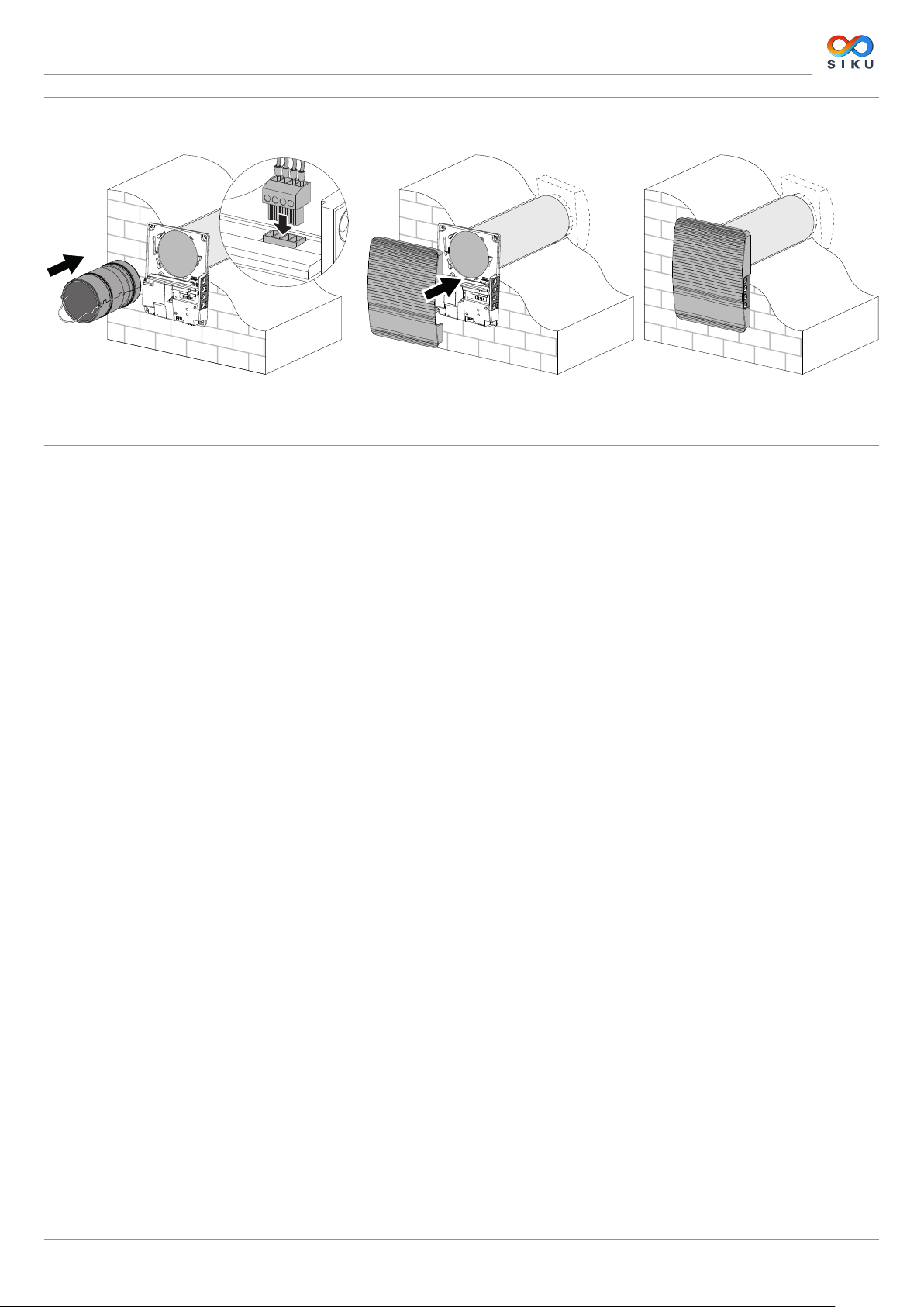
7. Insert the cartridge into the air duct and insert the plug cartridge to the controller. Re-install the front panel of the indoor unit rear part.
www.siku.cc
9

CONNECTION TO POWER MAINS AND CONTROL
POWER OFF THE POWER SUPPLY PRIOR TO ANY OPERATIONS WITH THE UNIT.
THE UNIT MUST BE CONNECTED TO POWER SUPPLY BY A QUALIFIED ELECTRICIAN.
THE RATED ELECTRICAL PARAMETERS OF THE UNIT ARE GIVEN ON THE
MANUFACTURER’S LABEL.
ANY TAMPERING WITH THE INTERNAL CONNECTIONS IS PROHIBITED
AND WILL VOID THE WARRANTY.
SIKU RV 25 W Pro WiFi V2
The ventilator is rated for connection to single-phase
AC 100 - 240 V / 50 (60) Hz power mains. The installation of power
cables is described in the Installation and set-up section.
Connect the unit to power mains uing durable, insulated and heatresistant conductors (cables and wires). The total minimum cross
section for the power cable must be 0.5 up to 0.75 mm2. The actual
wire cross section selection must be based on the maximum load
current, maximum conductor temperature depending in the wire type,
insulation, length and installation method.
Use copper wires for all the electric connections!
Connect the unit to power mains via the terminal block in compliance
with the wiring diagram and terminal designation. Connect the
ventilator to power supply through an automatic circuit breaker with
electromagnetic trip integrated into the home wiring system. The
rated trip current of the automatic circuit breaker or the safety fuses
must exceed the maximum current consumption of the unit, refer to
the Technical data section.
The recommended trip current of the circuit breaker or safety fuse is the
next current in the standard trip current row following the maximum
current of the connected unit.
WIRING DIAGRAM
1~100-240 V
50 (60) Hz
QF
L
N
Klemmenmarkierung auf dem
LT: circuit for activation of Boost mode
LT: Stromkreis zur Aktivierung des Betriebs Boost
L: line
L: Phasenleiter
N: neutral
N: Neutralleiter
QF: circuit breaker
QF: Leitungsschutzschalter
S: external relay sensor (switch for activation of Boost mode).
S: externer Relaissensor (Relais zur Aktivierung des Betriebs Boost).
S
Terminal designation on
the wiring diagram:
Anschlussschema:
LT(1)
L(2)
N(3)
10
ON DIP
1 2 3 4
Dip-Schalter
DIP switch
Reset to factory settings
Taste zum Zurücksetzen
button
auf Werkseinstellungen
Öffnungssensor der
Abdeckung
Cover opening sensor
USB-Schnittstelle
USB socket
VENTILATOR SETUP
Prior to operating the ventilator set it up using the DIP switch. It is located on
the controller circuit board.
To access the DIP switch take off the front panel of the indoor unit.
To reset the ventilator to the factory settings keep the reset button under the
front panel pressed for 5 seconds till a long beep. Reset to the factory settings
is also possible via the mobile application.
www.siku.cc

SIKU RV 25 W Pro WiFi V2
1
OFF: Master unit.
1
ON: Slave unit.
2
OFF: shutdown of the ventilator in the Standby mode.
2
ON: the ventilator is running at the first speed in the Standby mode.
3
OFF: the ventilator runs in the extract mode.
3
ON: the ventilator runs in the supply mode.
4
OFF: standard operation mode.
4
ON: programming mode.
POSITIONING OF THE DIP SWITCH
Setup of ventilator operation mode
Standby mode setup
Ventilation mode setup
Programming mode
Warning! The programming mode can be switched by the service engineers only!
VENTILATOR CONTROL
The ventilator is operated with the following controls:
• the buttons located on the side of the indoor unit (see the figure below)
• the mobile application "SIKU RV WIFI" installed on a smartphone or a tablet
• The Smart home application. The ventilators must be connected to the Smart home application in compliance with user’s manual
for this application.
Ein/Aus
On/O
Lüftungsstufe
Speed
Die Einstellung der Lüftungsstufe erfolgt zyklisch:
The speed selection sequence is follows:
low-medium-high.
niedrig-mittel-hoch.
Wärmerückgewinnung
Regeneration
Die Lüftungsanlage läuft im Reversbetrieb mit
The ventilator runs in the reversible mode with heat and
Wärme- und Feuchterückgewinnung.
humidity recovery.
www.siku.cc
Lüftung
Ventilation
The ventilator runs in the supply or extract mode with the set
Die Lüftungsanlage läuft in Zu- oder Abluftbetrieb
speed.
in der eingestellten Lüftungsstufe.
11

SIKU RV 25 W Pro WiFi V2
VENTILATOR CONTROL WITH THE BUTTONS ON THE INDOOR UNIT
On/Off
The speed selection sequence is follows: low-medium-high. The speed of all the interconnected ventilators in the
network is set with the Master unit.
I: permanent glowing of the indicator indicates running of the ventilator at the low speed.
Blinking of the indicator indicates activation of the timer Night mode.
I and II: permanent glowing of the indicators I and II indicates running of the ventilator at the medium speed.
I, II and III: permanent glowing of the indicators I, II and III indicates running of the ventilator at the high speed.
Synchronous blinking of the indicators I, II and III indicates activation of the timer in the Party mode or the
turn-off delay timer in the Boost mode in case of triggering of the integrated humidity sensor or the connected
external relay sensor. Alternate blinking of the indicators I, II and III indicates running of the ventilator at the speed
set with the mobile application using the slider selector for manual speed setting or activation of the scheduler.
Regeneration mode
Rotation direction of the fan is changed. Heat regeneration is accomplished in the Regeneration mode. To
enable operation of the ventilators in opposite direction change the position of the DIP switch No. 3.
Filter clogging indicator. The indicator starts blinking 90 days after installation of the cartridge. In this case clean
or replace the filters (see the «Technical maintenance» section).
F
After replacement of the filters reset the filter timer using the mobile application or press and hold the
button on the indoor unit of the Master unit for 5 seconds, until a signal beeps.
Alarm indicator. In case of a failure the Alarm indicator on the indoor unit starts to glow or to blink.
Reasons for glowing of the indicator:
• Alarm shutdown of a ventilator caused by another defective ventilator in the network.
Reasons of alarm blinking:
A
No glowing of the indicators «Regeneration» and «Ventilation» indicates activated supply ventilation mode of the ventilator..
M
Synchronous blinking of all the indicators on the ventilator casing indicates the activated Setup mode.
• Battery charge is below the allowable limit
• No connection between the Master unit and the router
• Alarm shutdown of a ventilator. This ventilator causes shutdown of all interconnected ventilators in the
network.
In case of communication loss of the Master unit with the router longer than 20 seconds the Master unit goes
to the Standby mode and the Slave units signal of communication loss with the Master unit. After resumption
of the connection the Slave units automatically get synchronized with the Master unit.
Ventilation mode
The ventilator operates in the supply or extract mode with the set speed. The fan rotation direction depends on
the position of the DIP switch 3.
Permanent glowing of the indicator identifies the Master unit in the network.
The blinking Indicator identifies the Slave unit in the network and no connection with the Master unit.
No glowing of the indicator identifies the Slave unit connected with the Master unit.
12
www.siku.cc

SIKU RV 25 W Pro WiFi V2
VENTILATOR CONTROL WITH MOBILE APPLICATION
To enable ventilator control with a mobile device install the App SIKU RV WIFI application.
SIKU RV WIFI - App Store SIKU RV WIFI Play Market
Your mobile device must have the operation system matching the following parameters:
• iOS – iOS: 8 or later. Compatible with iPhone, iPad, iPod.
• Android – Android: 4 or later.
CONNECTION OF MOBILE APPLICATION TO THE VENTILATOR
Download the SIKU RV WIFI application and install it on the mobile device.
If there is no connection with the ventilator during launching of the application the mobile device displays the following message:
Warning!
No communication with the
device!
Check the connection.
By default, the ventilator operates as a Wi-Fi access point. Connect the mobile device to the Wi-Fi access point with the name (FAN: + 16
ID Number characters) stated on the ventilator casing under the front panel.
Wi-Fi access point password: 11111111.
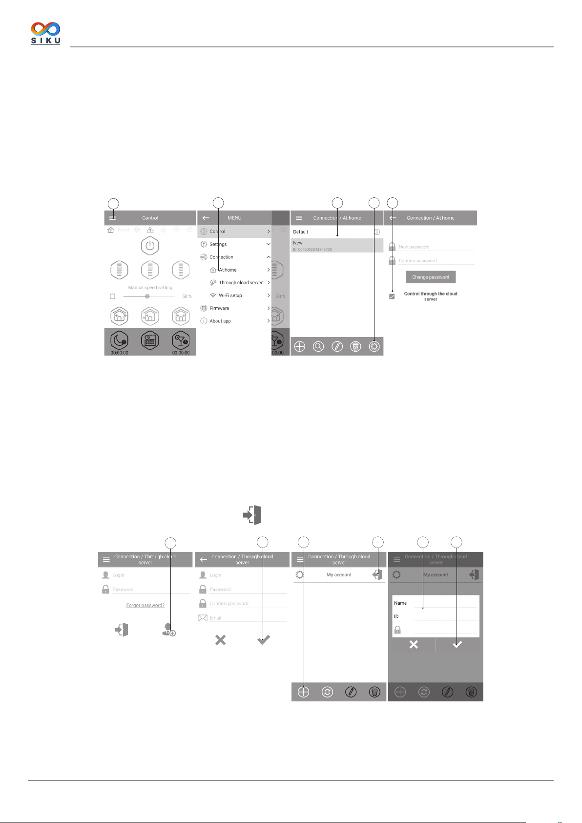
1 2 4 56 873
Enter the SIKU RV WIFI app and create a new connection as follows:
1. Enter the app menu.
2. Select Connection - At home.
3. If mobile device is connected to the Wi-Fi access point without router, select the default connection.
4. In case of connection via router start searching for ventilators in the network.
5. Find the new connection in the list and highlight its ID.
6. Edit the connection details.
7. If necessary, re-name the connection and enter the ventilator password. By default the ventilator password is 1111 (is highlighted in
the entry line automatically). The password 1111 is a default password for the ventilator.
WARNING! At this stage the password for the ventilator cannot be changed.
8. Confirm the entered data.
Once the connection has been established, go to the app menu and choose Control.
www.siku.cc
13

DESCRIPTION OF MOBILE APPLICATION CONTROL BUTTONS
ON/Standby. The Standby mode is determined by the DIP switch No. 2
position (see page 11).
SIKU RV 25 W Pro WiFi V2
Selection of the pre-set speed: low, medium and high speed respectively.
Manual speed setting. Check the scroll bar to activate it.
Ventilation.
The ventilator operates either in the extract or supply mode at the set
speed. The air direction is determined by the DIP switch No. 3 position
(see page 11).
Regeneration.
The fan rotation direction changes to opposite each 70 seconds. This
operation mode enables heat recovery.
Air supply.
The ventilator operates exclusively in supply mode.
Night mode. Activation of the low speed timer (the default setting is 8
hours, adjustable in the menu Settings-Timers).
Scheduler.
Activation of the week scheduled operation.
Party mode.
Activation of the high speed timer (4 hours by default, adjustable in the
menu Settings-Timers).
DESCRIPTION OF MOBILE APPLICATION INDICATORS
Current type of connection to the ventilator.
Home connection or connection via a cloud server through Internet respectively.
Maximum speed activation indicator. It goes on after actuation of the humidity or any other connected external relay
sensor. When this mode is active, all the other modes are disabled. After air humidity decrease or disappearance
of signal from an external relay sensor after countdown of the turn-off delay timer (default setting 30 minutes) the
ventilator reverts to the previous mode. Press the Power button to deactivate this operation mode.
Filter replacement indicator. To reset the filter timer go to Menu- Settings-Filter.
Alarm indicator. The indicator glows in case of alarm and it has two colours.
The indicator glows red in case of alarm shutdown of the ventilator.
The indicator glows orange if battery is not available or the battery charge is low.
Humidity indicator. It glows if the indoor humidity is above the set point.
External relay sensor indicator. It glows, if the sensor is actuated.
When simultaneously activating several operation modes that exclude each other, the operation mode selection is done according to
the following priority:
1. Night mode timer or Party mode timer.
2. Standby.
3. Boost.
4. Scheduler.
5. Regular mode.
14
www.siku.cc

SIKU RV 25 W Pro WiFi V2
VENTILATOR PASSWORD CHANGE
To change the ventilator password in the mobile application go to Menu--
Connection-At home.
1. Select the connection type and press the Settings button.
2. Enter and confirm the password.
3. Press the Change Password button.
TIMER SETUP
To set the Night mode, Party mode timer and the turn-off delay timer for the Boost mode, go to Menu
-Settings -Timers in the mobile application.
The Night mode timer defines switch delay to the low speed after activation of the Night mode (8
hours by default).
The Party timer defines switch delay to the high speed after activation of the Party mode (4 hours
by default).
The turn-o delay timer for the Boost mode defines switch delay to the high speed after triggering
of any sensor and reset of the sensor to the standard status.
1 2 3
SENSOR SETUP
To set up sensor operation via the mobile application go to Menu - Settings -Sensors.
Humidity sensor: actuation of the humidity sensor. When the indoor humidity exceeds the set point, the
ventilator goes to the high speed. When the indoor humidity drops down below the set point, the turnoff delay timer for the Boost mode is activated. After the delay timer counterdown, the ventilator reverts
to the previous speed setting. After the ventilator operation in the Boost mode comes to the end, the
ventilator reverts to the previous speed setting.
Relay sensor: triggering of the external relay sensor. As the NO contact of the external relay sensor is
closed, the ventilator goes to the high speed. As the NO contact opens, the turn-off delay timer for the
«Boost» mode is activated. After the ventilator operation in the Boost mode comes to the end, the ventilator
reverts to the previous speed setting.
This ventilator model can’t be connected to 0-10 V sensor, so setup of this sensor is disabled.
www.siku.cc
15

DATE AND TIME SETUP
To set up the ventilator date and time, go to Setting - Date and time.
Current time: set the current time.
Current date: set the current date.
WEEKLY SCHEDULE SETUP
To set up the weekly schedule in the mobile application go to Menu - Settings - Scheduler.
The weekly schedule can be set by means of 4 time intervals available for each day of the week.
You can select one of the three fan speeds or Standby for each time interval.
To receive the current settings for the selected day of the week press the Receive button.
To apply the selected settings for the selected day of the week press the Apply button.
For proper operation of the week scheduler check the settings for the date and time.
SIKU RV 25 W Pro WiFi V2
FILTER TIMER RESET
The ventilator filters must be serviced after every 90 hours of continuous operation. The need to replace
the filters is communicated by the indicator in the upper section of the Control menu. Replace the
filter and reset the filter timer.
To reset the filter timer via the mobile application go to Menu - Settings -Filter. Then press the Reset
lter timer button.
The 90 days are counted on the master ventilator only.
The filter replacement indication is replicated on all the Slave units. In this case replace the filters on all
the ventilators in the network. After filter timer reset the filter replacement indicator goes off on all the
connected ventilators.
The filter timer can also be reset by means of the button on the indoor unit (see page 12).
RESET TO FACTORY SETTINGS
To reset to the factory settings via the mobile application go to Menu - Setting - Factory settings. Then
press the Reset to factory settings button.
WARNING!
Reset to the factory settings may result in losing Wi-Fi connection with the device.
16
www.siku.cc

SIKU RV 25 W Pro WiFi V2
WIRELESS CONNECTION OF SEVERAL VENTILATORS
The ventilator has two operation modes.
Master unit (Master). The ventilator acts as a Master unit. The Slave units and the mobile devices are connected to the Master unit via
the Wi-Fi connection. The Master unit is controlled via the mobile application or the sensor buttons on the ventilator casing. The control
signal is automatically transmitted to all the Slave units in the network. In this mode the ventilator responds to signal from the sensors
and goes to a respective operation mode.
Slave unit (Slave). The unit acts as a Slave unit in the network. The ventilator responds to the control signals from the Master unit only.
Any other signals from other controls are ignored. In this mode the ventilator does not respond to the signals from the sensors. In case of
communication loss with the Master unit longer than 20 seconds the ventilator goes to the Standby mode.
WIFI PARAMETER SETUP
Setup of the Wi-Fi parameters is only possible on Master units. To set up ventilator Wi-Fi parameters via the
mobile app go to Menu - Connection - WI-FI setup.
Press the Receive button to display the current Wi-Fi settings.
Select one of the Wi-Fi operation modes:
Access point: access point mode without a home router.
Select the desired security level for the Access point mode:
• Open: open Wi-Fi network, not protected with password.
• WPA PSK: password-protected. The encryption technology based on the WPA protocol does not ensure
full security.
• WPA2 PSK: password-protected. The encryption technology is for modern networks.
• WPA/WPA2 PSK: password-protected (recommended). This combined technology activates WPA and
WPA2 and provides compatibility with any electronic devices.
Enter your access point password and press the Apply button.
Client: client mode. The ventilator operates in the home router network.
Enter the home router details and the IP address type for the client mode.
Enter the name of the Wi-Fi home router access point.
Enter the password for the Wi-Fi home router access point.
Select IP address type:
DHCP: the IP address is set up automatically upon connection to the home router (recommended).
Static: enables manual entry of the desired IP address, subnet mask and default gateway. These settings are
recommended for expert users only. Select this IP address type at your own risk.
Then press the Apply button.
www.siku.cc
17

SIKU RV 25 W Pro WiFi V2
VENTILATOR WIRELESS CONNECTION DIAGRAMS
Wiring diagram 1
Connection of up to 8 Slave units or mobile devices to the Master
unit with its own wireless access point.
Wiring diagram 2
Slave Nr.1 Slave Nr.2 Slave Nr. N
Slave No.1
Slave No.2 Slave No.N
Master-Anlage
Master
mit WLAN-Zugangspunkt
with a Wi-Fi access point
Mobile device
Mobilgerät
The Master units, the Slave units and the mobile devices are connected to a Wi-Fi access point of the router.
In this case, the Master unit can operate with the number (N) of Slave units, limited by the technical characteristics of the router.
Router
Router
mit WLAN-Zugangspunkt
with it’s wireless access point
Mobilgerät Mobilgerät
Master Slave Nr.1 Slave Nr. N
Master Slave No.1
Slave No.N
mobile device
mobile device
If the Wi-Fi router capacity is not enough to connect a required number of the ventilators, you may use an extra wireless access point to
connect the other units. Optionally connection of several Master units to the network for arranging a zone control is also possible.
Router
Router
mit WLAN-Zugangspunkt
with it’s wireless access point
Mobilgerät Mobilgerät
Master Slave Nr.1 Slave Nr. N
Slave No.1
Slave No.N
mobile device
mobile device
18
Zusätzlicher WLAN-Zugangspunkt
extra wireless acess point
Slave Nr. N+1 Slave Nr. N+N
Slave No.N+1
Slave No.N+N
Mobilgerät Mobilgerät
mobile device
mobile device
www.siku.cc

SIKU RV 25 W Pro WiFi V2
CONNECTING MASTER AND SLAVE VENTILATORS
WHILE COMPLETING THE CONNECTION MAKE SURE THAT THE SLAVE UNITS ARE
WITHIN COVERAGE OF THE BUILTIN WIFI IN THE MASTER UNIT
To connect a Master and a Slave unit set the DIP switches on each ventilator to set it as a Master or the Slave unit (see page 11).
Then set up the Wi-Fi parameters of the master unit (see page 17).
AFTER CHANGING THE WIFI PARAMETERS OF THE MASTER VENTILATOR REPEAT THE
CONNECTION STEPS!
Press and hold the Ventilation button on the Master unit casing. Wait for the beep and the blinking of all the LED lights on the
unit casing. Repeat the steps with all the Slave units and wait for the beep when all the LED lights stop blinking on each Slave unit. Set
the Master unit to the normal operation mode. Press and hold the Ventilation button. Wait for the beep and going down of all the
LED lights.
Note: If the home router works in conjunction with several Wi-Fi access points and the ventilators require connection to different access
points:
• Connect the Master unit to the first Wi-Fi access point.
• Complete the connection with the first group of Slave units.
• Connect the Master unit to the second Wi-Fi access point.
• Complete the connection with the second group of Slave units.
SPECIAL SETUP MODE
In the event of losing the Wi-Fi password or the Master unit password or in other cases use the recovery Setup mode to restore access
to the ventilator functions. To enter the special setup mode, press and hold the Ventilation button on the ventilator casing for 5
seconds, until the beep and blinking of all the LED lights.
The ventilator continues in this mode for 3 minutes and then automatically revert to the previous settings. To exit the Setup mode
immediately once again press and hold the Ventilation button on the ventilator casing for 5 seconds, until the beep and shutdown
of all the LED lights.
In this mode the following settings are available:
• Wi-Fi network name: Setup mode.
• Wi-Fi password: 11111111.
• The unit password cannot be read.
BATTERY REPLACEMENT
The Alarm indicator on the ventilator casing blinks, when the battery charge
is low. The mobile app will also display the , warning and show the
following message on pressing the indicator icon. Low battery power may
cause disruptions in the weekly schedule operation. Power off the unit before
replacing the battery. After replacing the battery re-set the time and date.
The battery is located on the control circuit board. Power off the ventilator
to replace the battery, remove the front panel and the cover protecting the
control circuit board. Remove the battery and install the new one.
Battery type: CR1220.
www.siku.cc
19
SIKU RV 25 W Pro WiFi V2
CLOUD SERVER CONNECTION
The ventilators can be controlled using the mobile app via a cloud server connection. This functions enables control of a single or
multiple ventilators connected according to Diagram 2 over any distance using the mobile app connected to the Internet.
By default the Control via cloud server function is disabled. To enable the function:
1. Enter the app menu.
2. Select Connection - At home.
3. Select the desired ventilator connection.
4. Enter the connection settings menu.
5. Enable Control via cloud server.
Note: With this function enabled any loss of Internet connection provided by the home server may result in temporary loss of
1
2 3 54
communication with the ventilator.
To control the master ventilator create a new account during the first connection through the cloud server. Re-use the account for all
further connection. Open the mobile app and go to Menu - Connection - Through cloud server:
1. Press the Add new account button.
2. Enter a login, a password and an e-mail address for password recovery. Then press the Apply button.
3. The app will log into the account automatically. Add a new master ventilator.
4. To exit the account press the respective button (if necessary).
5. Enter a ventilator name on your choice, the ventilator ID as stated on the casing under the front panel of the ventilator and the unit
password (1111 by default).
6. Confirm the entries.
To log into the account via the mobile app go to Menu - Connection - Through the cloud server.
Then enter the login and password and press the Enter button.
20
1 2 3 4 5 6
www.siku.cc
SIKU RV 25 W Pro WiFi V2
TECHNICAL MAINTENANCE
Maintenance of the ventilator means regular cleaning of the ventilator surfaces of dust and cleaning and replacement of the filters. To
enable access to the main serviced units follow the procedure described below. Turn off the ventilator from power supply with the help
of the automatic circuit breaker or the cut-out switch before.
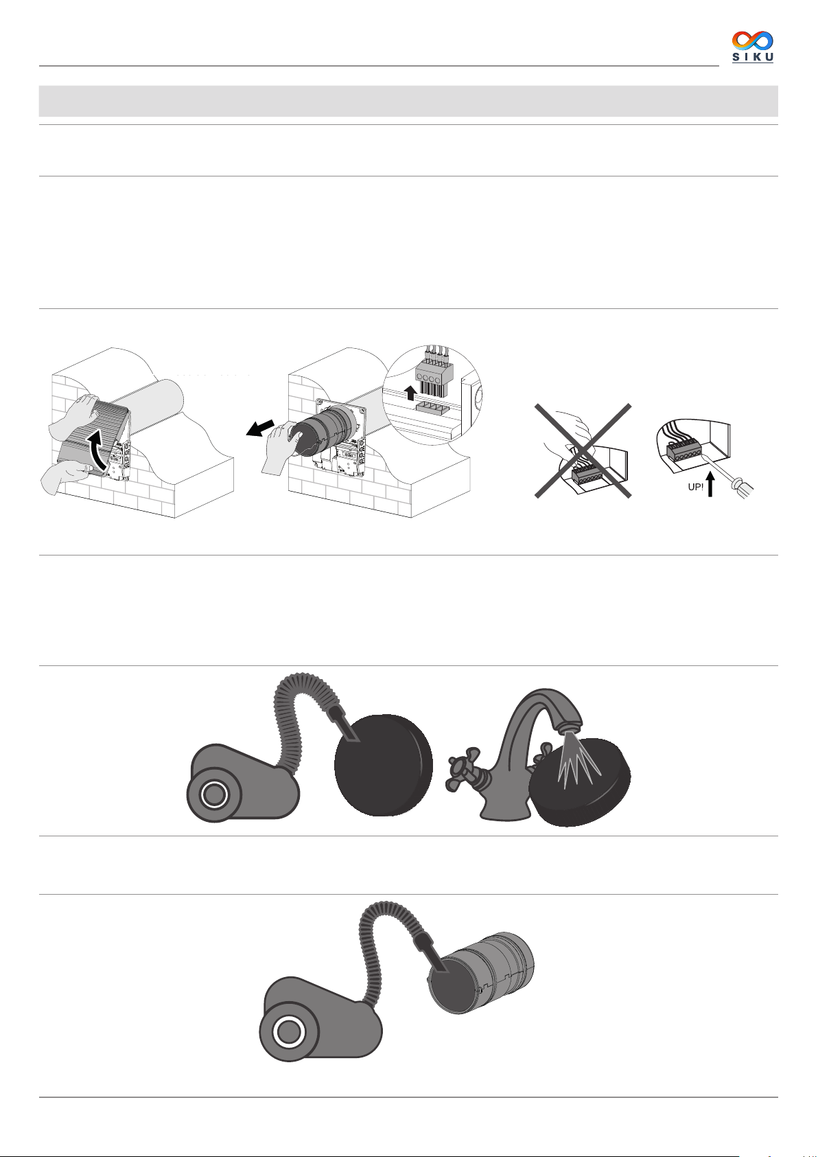
1. Press the lower lug to take off the front panel of the indoor unit. Make sure the thermal actuator rod is in lower position when installing
the front panel again. If the thermal actuator rod is up, please wait for about 2 minutes until it goes down.
2. Disconnect the connector from the control circuit board. While removing the connector do not pull the cable. Uplift it with a flat
screwdriver of a respective size.
3. Remove the cartridge from the air duct.
4. Remove the filters from the cartridge for cleaning.
5. After cleaning of the filters reassemble the ventilator in the reverse order.
Remove the filters from
Ziehen Sie die Filter
the cartridge.
aus der Patrone
Ziehen Sie nicht
Do not pull the wires!
an den Leitungen!
Use a flat screwd river to
Verwenden Sie dazu einen
disconnect the socket.
Schlitzschraubenzieher
Clean the filters as required, but not less than once in three months.
• In 90 days of non-stop operation the filter replacement indicator (Filter) starts glowing. Reset the filter timer using the mobile
application.
• Wash and let the filters dry out completely. Install the dry filters in the air duct.
• Vacuum cleaning is allowed.
• The filter rated service life is 3 years.
Even regular technical maintenance may not completely prevent dirt accumulation on the regenerator and the fan.
• Clean the regenerator regularly to ensure its high regeneration efficiency.
• Clean the regenerator with a vacuum cleaner not less than once a year.
www.siku.cc
21
SIKU RV 25 W Pro WiFi V2
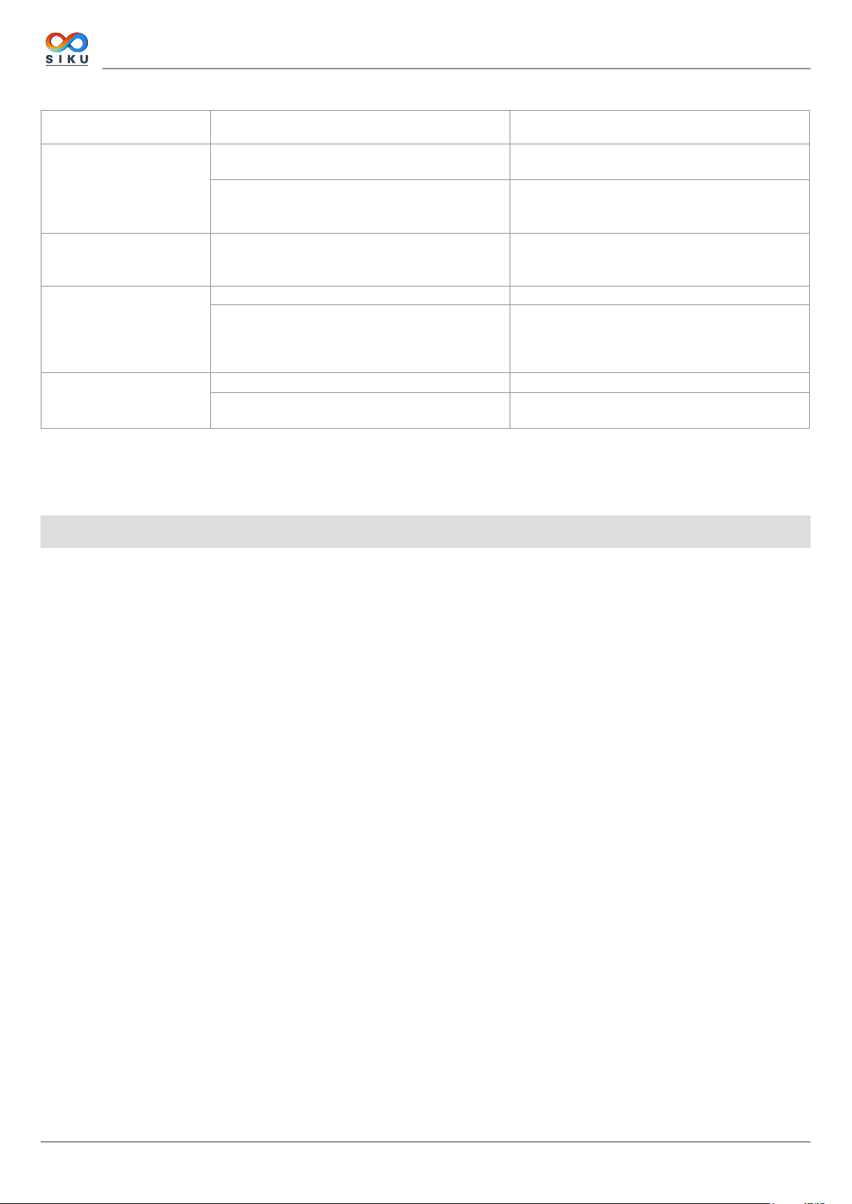
FAILURES AND TROUBLESHOOTING
Failure Possible reasons Troubleshooting
Make sure the power supply line is connected
correct, otherwise eliminate the connection error.
Turn the ventilator off. Troubleshoot the motor jam
and the impeller clogging.
Clean the blades. Turn the ventilator on.
Turn the ventilator off.
Contact the Seller for further information.
Clean or replace the filter. Clean the fan and the
regenerator.
Tighten the screws of the ventilator or the outer
ventilation hood.
The fan does not get started
during turning on.
Circuit breaker tripping
during turning of the
ventilator on.
Low air flow.
Noise, vibration.
No power supply
The motor is jammed, the impeller blades are
contaminated.
Overcurrent as a result of a short circuit in the
electric circuit.
Low set fan speed. Set the higher speed.
The filters, the fan or the regenerator are
contaminated.
The impeller is contaminated. Clean the impeller.
Loose screw connection in the ventilator casing or
in the outer ventilation hood.
STORAGE AND TRANSPORTATION REGULATIONS
• Store the unit in the manufacturer’s original packaging box in a dry closed ventilated premise with temperature range
von +5 °C bis +40 °C and relative humidity up to 70 %.
• Storage environment must not contain aggressive vapors and chemical mixtures provoking corrosion, insulation, and sealing
deformation.
• Use suitable hoist machinery for handling and storage operations to prevent possible damage to the unit.
• Follow the handling requirements applicable for the particular type of cargo.
• The unit can be carried in the original packaging by any mode of transport provided proper protection against precipitation and
mechanical damage. The unit must be transported only in the working position.
• Avoid sharp blows, scratches, or rough handling during loading and unloading.
• Prior to the initial power-up after transportation at low temperatures allow the unit to warm up at operation temperature for at least
3-4 hours.
22
www.siku.cc
SIKU RV 25 W Pro WiFi V2
MANUFACTURER’S WARRANTY
The product is in compliance with EU norms and standards on low voltage guidelines and electromagnetic compatibility. We hereby
declare that the product complies with the provisions of Electromagnetic Council Directive 2014/30/EU, Low Voltage Directive 2014/35/
EU and CE-marking Directive 93/68/EEC. This certificate is issued following test carried out on samples of the product referred to above.
The manufacturer hereby warrants normal operation of the unit for 24 Monaten after the retail sale date provided the user's observance
of the transportation, storage, installation, and operation regulations. Should any malfunctions occur in the course of the unit operation
through the Manufacturer's fault during the guaranteed period of operation, the user is entitled to get all the faults eliminated by the
manufacturer by means of warranty repair at the factory free of charge. The warranty repair includes work specific to elimination of faults
in the unit operation to ensure its intended use by the user within the guaranteed period of operation. The faults are eliminated by means
of replacement or repair of the unit components or a specific part of such unit component.
The warranty repair does not include:
• routine technical maintenance
• unit installation/dismantling
• unit setup
To benefit from warranty repair, the user must provide the unit, the user's manual with the purchase date stamp, and the payment
paperwork certifying the purchase. The unit model must comply with the one stated in the user’s manual. Contact the Seller for warranty
service.
The manufacturer’s warranty does not apply to the following cases:
• User’s failure to submit the unit with the entire delivery package as stated in the user’s manual including submission with missing
component parts previously dismounted by the user.
• Mismatch of the unit model and the brand name with the information stated on the unit packaging and in the user's manual.
• User’s failure to ensure timely technical maintenance of the unit.
• External damage to the unit casing (excluding external modifications as required for installation) and internal components caused
by the user.
• Redesign or engineering changes to the unit.
• Replacement and use of any assemblies, parts and components not approved by the manufacturer.
• Unit misuse.
• Violation of the unit installation regulations by the user.
• Violation of the unit control regulations by the user.
• Unit connection to power mains with a voltage different from the one stated in the user's manual.
• Unit breakdown due to voltage surges in power mains.
• Discretionary repair of the unit by the user.
• Unit repair by any persons without the manufacturer’s authorization.
• Expiration of the unit warranty period.
• Violation of the unit transportation regulations by the user.
• Violation of the unit storage regulations by the user.
• Wrongful actions against the unit committed by third parties.
• Unit breakdown due to circumstances of insuperable force (fire, flood, earthquake, war, hostilities of any kind, blockades).
• Missing seals if provided by the user’s manual.
• Failure to submit the user’s manual with the unit purchase date stamp.
• Missing payment paperwork certifying the unit purchase.
www.siku.cc
FOLLOWING THE REGULATIONS STIPULATED HEREIN WILL ENSURE A LONG AND
TROUBLEFREE OPERATION OF THE UNIT.
USER’S WARRANTY CLAIMS SHALL BE SUBJECT TO REVIEW ONLY UPON
PRESENTATION OF THE UNIT, THE PAYMENT DOCUMENT AND THE USER’S MANUAL
WITH THE PURCHASE DATE STAMP.
23

SIKU RV 25 W Pro WiFi V2
24
www.siku.cc

SIKU RV 25 W Pro WiFi V2
www.siku.cc
25

SIKU RV 25 W Pro WiFi V2
26
www.siku.cc

SIKU RV 25 W Pro WiFi V2
CERTIFICATE OF ACCEPTANCE
Unit Type Single-room reversible energy regeneration ventilator
Model SIKU RV __________________
Serial Number
Manufacture Date
Quality Inspector’s
Stamp
SELLER INFORMATION
Seller
Address
Phone Number
E-mail
Purchase Date
This is to certify acceptance of the complete unit delivery with the user’s manual. The warranty terms are
acknowledged and accepted.
Customer’s Signature
INSTALLATION CERTIFICATE
The SIKU RV __________________ unit has been connected to power mains pursuant to the
requirements stated in the present user’s manual.
Seller
Address
Phone Number
Installation
Technician’s Full Name
Installation Date: Signature:
The unit has been installed in accordance with the provisions of all the applicable local and national construction,
electrical and technical codes and standards. The unit operates normally as intended by the manufacturer.
Signature:
Seller’s Stamp
Installation Stamp
WARRANTY CARD
Unit Type Single/room reversible energz regeneration ventilator
Model SIKU RV __________________
Serial Number
Manufacture Date
Purchase Date
Warranty Period
Seller
www.siku.cc
Seller’s Stamp
27

SIKU VertriebsgmbH Tel.: +43 2262 61 521
Bundesstraße 5 Fax: +43 2262 61 520
2102 Bisamberg www.siku.cc
Austria office@siku.cc
BDA_50522_RV25W-V2_EN-01
 Loading...