

Page 1
300/18
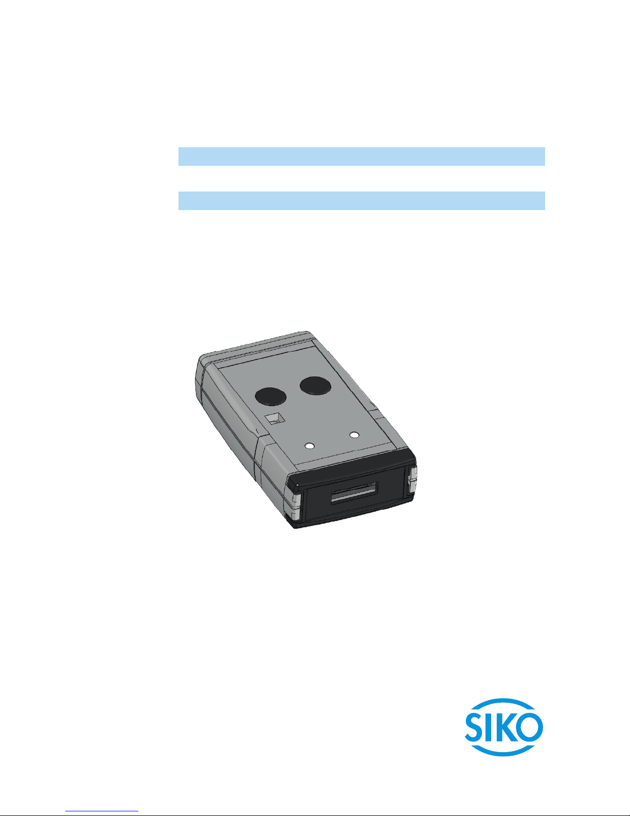
ProTool SGH
Programmiersoftware für SGH10, SGH25 und SGH50
Originalmontageanleitung Deutsch Seite2
Programming software for SGH10, SGH25 und SGH50
Translation of the Original Installation Instructions English page13
Page 2
ProTool SGH
Deutsch
ProTool SGH · Datum 04.09.2018 · Art. Nr. 89757 · Änd. Stand 300/18
2
Inhaltsverzeichnis
1 Dokumentation . . . . . . . . . . . . . . . . . . . . 3
2 Sicherheitshinweise . . . . . . . . . . . . . . . . . . 3
2.1 Bestimmungsgemäße Verwendung . . . . . . . . . . . 3
2.2 Kennzeichnung von Gefahren und Hinweisen . . . . . . 3
2.3 Zielgruppe . . . . . . . . . . . . . . . . . . . . 4
2.4 Grundlegende Sicherheitshinweise . . . . . . . . . . . 4
3 Installation . . . . . . . . . . . . . . . . . . . . . . 5
3.1 Treiberinstallation . . . . . . . . . . . . . . . . . 5
3.2 Programminstallation . . . . . . . . . . . . . . . . 5
3.3 Anschluss . . . . . . . . . . . . . . . . . . . . . 5
4 Funktionsbeschreibung . . . . . . . . . . . . . . . . . 8
4.1 Programmoberfläche und Funktionen . . . . . . . . . . 8
4.2 Grenzwertabgleich : (Nur Ausgang Analog) . . . . . . 11
4.3 Fehlerbeschreibung . . . . . . . . . . . . . . . . 12
5 Technische Daten . . . . . . . . . . . . . . . . . . 13
Page 3
ProTool SGH
Dokumentation Deutsch
ProTool SGH · Datum 04.09.2018 · Art. Nr. 89757 · Änd. Stand 300/18
3
1 Dokumentation
Zu diesem Produkt gibt es folgende Dokumente:
• Montageanleitung beschreibt die mechanische und die elektrische
Montage mit allen sicherheitsrelevanten Bedingungen und der dazugehörigen technischen Vorgaben.
Diese Dokumente sind auch unter
"http://www.siko-global.com/p/protool-sgh" zu finden.
2 Sicherheitshinweise
2.1 Bestimmungsgemäße Verwendung
Die Programmier-Software ProToolSGH bietet unter Windows 10/98/
NT/2000/XP/Vista/7/8/8.1 die Möglichkeit, den Seilzuggeber SGHXXschon vor der Montage mit entsprechenden Parametern zu programmieren. Der Umgang mit dem Programm ist sehr einfach, da die Funktionen
mit Bezeichnungen benannt sind, die aus den Bestellmerkmalen des Seilzuggebers bekannt sind. Die Werte werden mittels Schaltflächen ausgewählt.
1. Beachten Sie alle Sicherheitshinweise in dieser Anleitung.
2. Eigenmächtige Umbauten und Veränderungen an dem Programmierkabel sind verboten.
3. Die vorgeschriebenen Betriebs- und Installationsbedingungen sind
einzuhalten.
2.2 Kennzeichnung von Gefahren und Hinweisen
Sicherheitshinweise bestehen aus dem Signalzeichen und einem Signalwort.
Gefahrenklassen
Unmittelbare Gefährdungen die zu schweren irreversiblen Körperverletzungen mit Todesfolge, Sachschäden oder ungeplanten Gerätereaktionen
führen können, sofern Sie die gegebenen Anweisungen missachten.
Gefährdungen die zu schweren Körperverletzungen, Sachschäden oder
ungeplanten Gerätereaktionen führen können, sofern Sie die gegebenen
Anweisungen missachten.
GEFAHR
WARNUNG
Page 4
ProTool SGH
Sicherheitshinweise Deutsch
ProTool SGH · Datum 04.09.2018 · Art. Nr. 89757 · Änd. Stand 300/18
4
Gefährdungen die zu leichten Verletzungen, Sachschäden oder ungeplanten Gerätereaktionen führen können, sofern Sie die gegebenen Anweisungen missachten.
Wichtige Betriebshinweise die die Bedienung erleichtern oder die bei
Nichtbeachtung zu ungeplanten Gerätereaktionen führen können und
somit möglicherweise zu Sachschäden führen können.
Signalzeichen
2.3 Zielgruppe
Die Montageanleitung wendet sich an das Projektierungs-, Inbetriebnahme- und Montagepersonal von Anlagen- oder Maschinenherstellern,
das über besondere Kenntnisse innerhalb der Antriebstechnik verfügt.
Dieser Personenkreis benötigt fundierte Kenntnisse über die notwendige
Programmierung eines Seilzuggebers und dessen Integration in die komplette Maschinenanlage.
Nicht ausreichend qualifiziertes Personal
Personenschäden, schwere Schäden an Maschine und Geräten werden
durch nicht ausreichend qualifiziertes Personal verursacht.
` Projektierung, Inbetriebnahme, Montage und Wartung nur durch
geschultes Fachpersonal.
` Dieses Personal muss in der Lage sein, Gefahren, welche durch die
mechanische, elektrische oder elektronische Ausrüstung verursacht
werden können, zu erkennen.
Qualifiziertes Personal
sind Personen, die
• als Projektierungspersonal mit den Sicherheitsrichtlinien der Elektround Automatisierungstechnik vertraut sind;
• als Inbetriebnahme- und Monatagepersonal berechtigt sind, Stromkreise und Geräte/Systeme gemäß den Standards der Sicherheitstechnik in Betrieb zu nehmen, zu erden und zu kennzeichnen.
2.4 Grundlegende Sicherheitshinweise
Explosionsgefahr
` Programmierkabel nicht in explosionsgefährdeten Zonen einsetzen.
VORSICHT
ACHTUNG
WARNUNG
GEFAHR
Page 5
ProTool SGH
Installation Deutsch
ProTool SGH · Datum 04.09.2018 · Art. Nr. 89757 · Änd. Stand 300/18
5
3 Installation
Vor dem Einsatz des ProToolSGH müssen die entsprechend Treiber passend
zur verwendeten Windows-Version installiert werden.
3.1 Treiberinstallation
Es sind Administrationsrechte für die Treiberinstallation notwendig!
Die Installation der USB-Treiber ist pro Rechner nur einmalig notwendig.
Den Link zu den Treibern finden Sie auf unserer Homepage.
3.2 Programminstallation
Die Software-Datei "ProToolSGH.EXE" kann direkt von der Homepage herunter geladen werden.
3.3 Anschluss
Anschluss am Seilzugeber mit KV1H und Programmierkabel (M12)
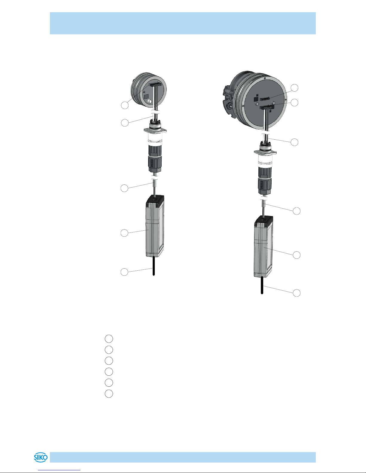
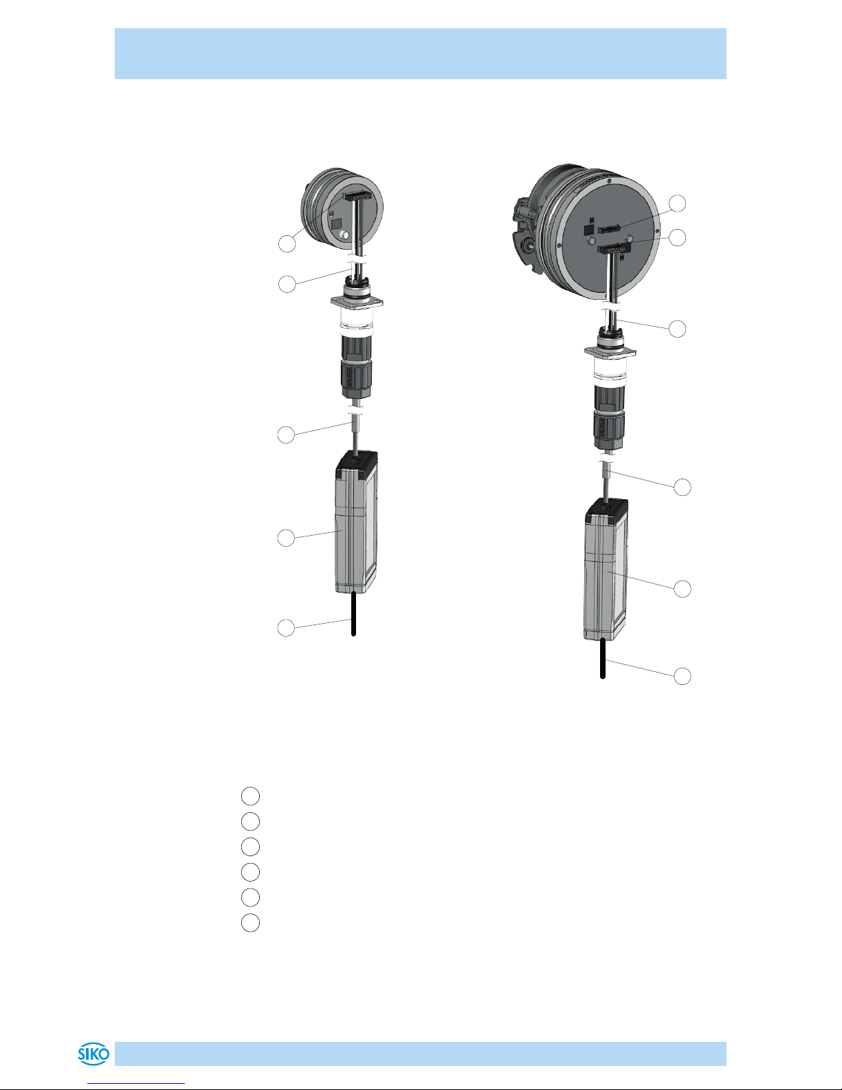
Die Parametrierung des Seilzuggebers erfolgt über das mitgelieferte Programmierkabel 1 (M12). Das Programmierkabel 1 wird über die Kabelverlängerung KV1H 2 mit dem SGHXX verbunden (siehe Abb. 1).
Die KV1H darf nur mit der Anschlußbelegung A1 verwendet werden.
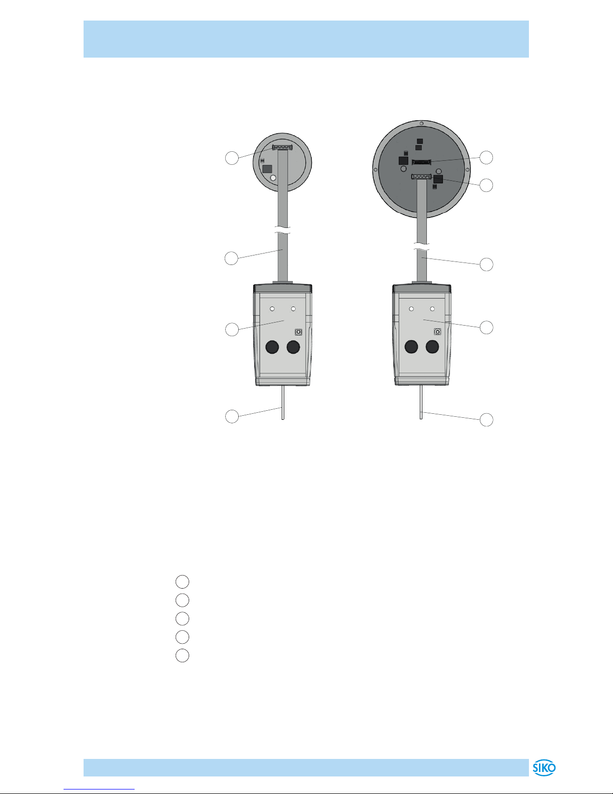
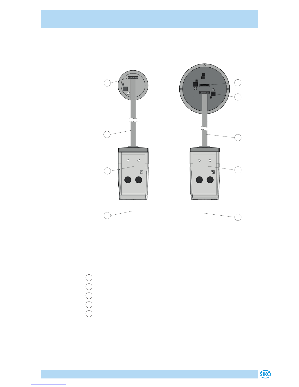
Anschluss am Seilzugeber mit Flachbandkabel (Anschluss im
unverbauten Zustand)
Vor dem Einbau des Seilzuggebers in den Zylinder kann der Anschluss des
ProTool SGH auch direkt mit der Flachbandleitung erfolgen. Diese ist im
Leiterplattenverbinder 1
5
und 2
6
einzustecken (siehe Abb. 2).
Anschluss am Computer
Für die Anbindung an die Programmier-Software muss das ProTool SGH
3
mit dem USB-Kabel
4
am Computer verbunden werden.
Alle Verkabelungsarbeiten dürfen nur im stromlosen Zustand erfolgen.
Alle redundanten Seilzuggeber müssen auch über den Leiterplattenverbinder 2
6
parametriert werden.
ACHTUNG
ACHTUNG
ACHTUNG
ACHTUNG
Page 6
ProTool SGH
Installation Deutsch
ProTool SGH · Datum 04.09.2018 · Art. Nr. 89757 · Änd. Stand 300/18
6
Abb. 1: Anschluss am Seilzugeber mit KV1H und Programmierkabel
2
1
Computer
3
4
5
2
1
Computer
3
4
5
6
SGHXX SGHXX (redundant)
1
Programmierkabel
2
KV1H
3
ProTool SGH
4
USB-Kabel
5
Leiterplattenverbinder 1
6
Leiterplattenverbinder 2 (redundant)
Page 7
ProTool SGH
Installation Deutsch
ProTool SGH · Datum 04.09.2018 · Art. Nr. 89757 · Änd. Stand 300/18
7
Abb. 2: Anschluss am Seilzugeber mit Flachbandkabel
1
5
3
4
Computer
1
3
5
6
4
Computer
SGHXX SGHXX (redundant)
1
Flachbandkabel
3
ProTool SGH
4
USB-Kabel
5
Leiterplattenverbinder 1
6
Leiterplattenverbinder 2 (redundant)
Page 8
ProTool SGH
Funktionsbeschreibung Deutsch
ProTool SGH · Datum 04.09.2018 · Art. Nr. 89757 · Änd. Stand 300/18
8
4 Funktionsbeschreibung
Die Kommunikation zwischen PC und SGHXX ist nur möglich, wenn die
Betriebsspannung des SGHXX von der Software (Button 4) eingeschaltet wurde.
Software-Version
Nach dem Start ([START]+[Power SGH on] 4 ) der Protokoll-SGH-Software
(SW) erscheint in der Kopfzeile die SW-Version (z.B. V1.00).
4.1 Programmoberfläche und Funktionen
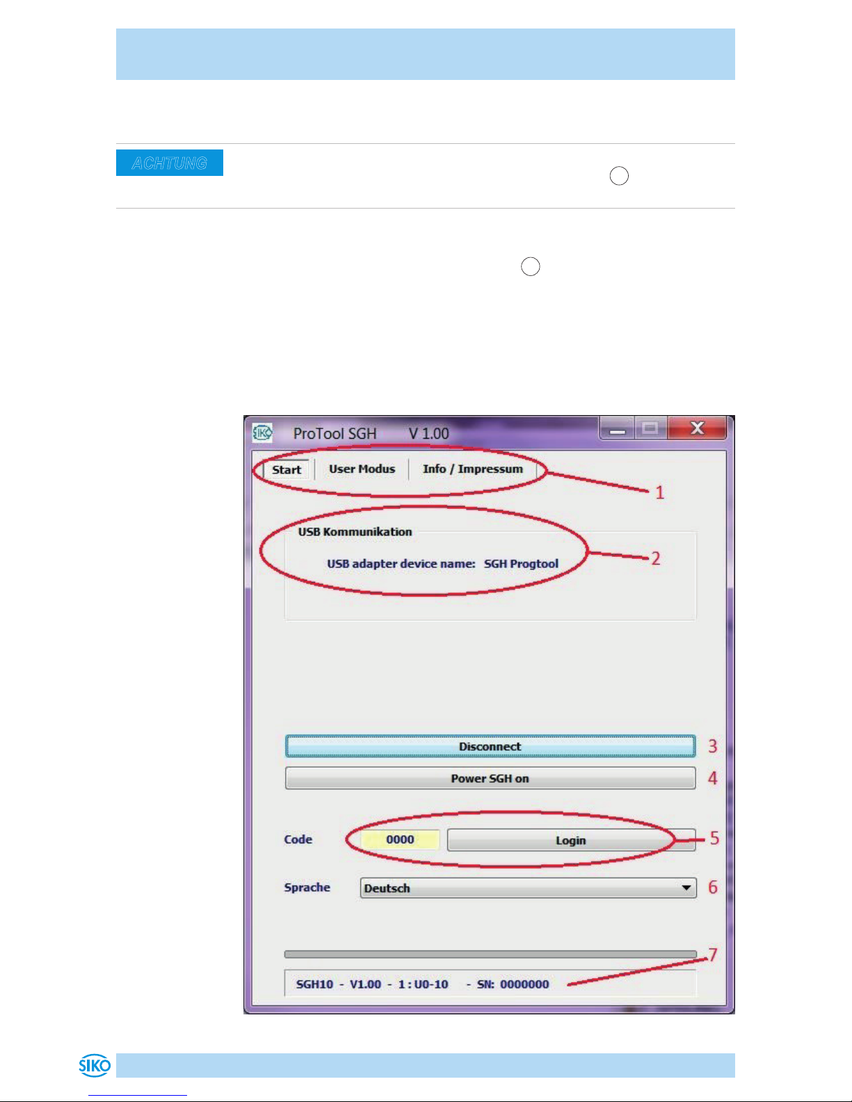
Reiter "Start"
ACHTUNG
Page 9
ProTool SGH
Funktionsbeschreibung Deutsch
ProTool SGH · Datum 04.09.2018 · Art. Nr. 89757 · Änd. Stand 300/18
9
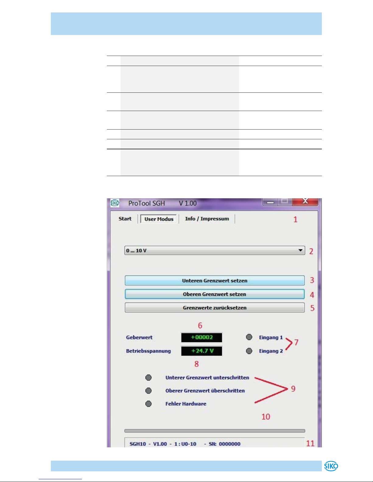
Nr. Beschreibung / Funktion Kommentar
1 Reiter: Wechsel mit Mausklick
2 Statusinformation über die Kommuni-
kation via USB zwischen PC und ProTool SGH
Hier Fehlerfrei
3 USB-Kommunikation ein- / ausschal-
ten
4 Betriebsspannung (24 V DC) für das
SGHXX ein- / ausschalten
5 Nur für werkseitige Verwendung
6 Sprachauswahl Deutsch / Englisch
7 Statusinformation des angeschlos-
senen SGHXX: Typ, Art der Ausgangs-
schaltung, Seriennummer
Nur bei USB-Kommunikation und Power on
Reiter "User Modus"
Page 10
ProTool SGH
Funktionsbeschreibung Deutsch
ProTool SGH · Datum 04.09.2018 · Art. Nr. 89757 · Änd. Stand 300/18
10
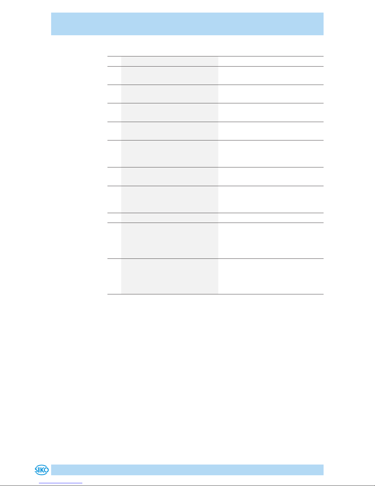
Nr. Beschreibung / Funktion Kommentar
1 Reiter: Wechsel mit Mausklick
2 Art des Analogausgangs para-
metrieren
Nicht bei Ausgang CAN
3 Unteren Grenzwert setzen Nicht bei Ausgang CAN (siehe
Kapitel 4.2.)
4 Oberen Grenzwert setzen Nicht bei Ausgang CAN (siehe
Kapitel 4.2 Grenzwertabgleich
5 Grenzwerte zurücksetzen Nicht bei Ausgang CAN (siehe
Kapitel 4.2)
6 Geberwertausgabe (ohne
Berücksichtigung der Grenz-
werte)
7 Statusanzeige der externen
Eingänge Lim 2 & LIM 2
Nicht bei Ausgang CAN
8 Betriebsspannung des SGHXX
(ca. 24 V DC gespeist aus der
USB-Schnittstelle)
9 Grenzwert- und Fehlerstatus Nicht bei Ausgang CAN
10 Geberwert als Balkendar-
stellung; grün innerhalb der
Grenzwerte; rot Grenzwert
über bzw. unterschritten.
11 Statusinformation des ange-
schlossenen SGHXX: Typ, Art
der Ausgangsschaltung, Seri-
ennummer
Nur bei USB-Kommunikation und
Power on
Page 11

ProTool SGH
Funktionsbeschreibung Deutsch
ProTool SGH · Datum 04.09.2018 · Art. Nr. 89757 · Änd. Stand 300/18
11
4.2 Grenzwertabgleich (Nur Ausgang Analog)
Unteren Grenzwert abgleichen über Programmier-Tool:
• Den SGHXX durch herausziehen des Seiles (Zylinders) an die Position
bringen, an der der minimale Analogwert (z.B. I 4-20mA; 4mA) ausgegeben werden soll.
• Drücken der LIM 1 Taste für >3 Sekunden.
Alternativ über Software:
• Betätigen des Buttons 3 „unteren Grenzwert setzen“ in der Software.
• Anschließend gibt der Geber seinen Minimalwert aus (Abhängig von
der Art des Ausgangs).
Oberen Grenzwert abgleichen über Programmier-Tool:
• Den SGHXX durch herausziehen des Seiles (Zylinders) an die Position
bringen, an der der maximale Analogwert (I 4-20mm; 20mA) ausgegeben werden soll.
• Drücken der LIM 2 Taste für >3 Sekunden.
Alternativ über Software:
• Betätigen des Buttons 4 „oberen Grenzwert setzen“ in der Software.
• Anschließend gibt der Geber seinen Maximalwert aus (Abhängig von
der Art des Ausgangs).
Page 12
ProTool SGH
Funktionsbeschreibung Deutsch
ProTool SGH · Datum 04.09.2018 · Art. Nr. 89757 · Änd. Stand 300/18
12
4.3 Fehlerbeschreibung
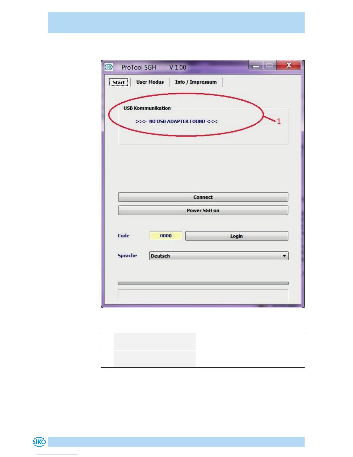
Nr. Beschreibung / Funktion Kommentar
1 Keine USB-Kommunikation - USB-Treiber nicht installiert
- ProTool SGH nicht mit PC verbunden
2 Keine Statusinformation - Kommunikation mit dem SGHXX ist
ausgeschaltet
Page 13
ProTool SGH
Technische Daten Deutsch
ProTool SGH · Datum 04.09.2018 · Art. Nr. 89757 · Änd. Stand 300/18
13
5 Technische Daten
Mechanische Daten Ergänzung
Gehäuse Kunststo
Farbe Achatgrau, Himmelblau
Kabellänge 1.8 m USB 2.0 A Stecker - USB 2.0
Mini-B Stecker
0.3 m 8-pol. Flachverbinder zum
Geber
Elektrische Daten Ergänzung
Betriebsspannung über USB
Anschlussart USB 2.0 Mini-B Buchse
Flachstecker 8-polig Buchse
Laborbuchse 2 Stück ø4 mm Strom- /Spannungsausgang
Umgebungsbedingungen Ergänzung
Umgebungstemperatur 0 ... 40 °C
Schutzart IP20
Page 14
ProTool SGH
English
ProTool SGH · Date 04.09.2018 · Art. No. 89757 · Mod. status 300/18
14
Table of contents
5 Documentation . . . . . . . . . . . . . . . . . . . 15
6 Safety information . . . . . . . . . . . . . . . . . . 15
6.1 Intended use . . . . . . . . . . . . . . . . . . . 15
6.2 Identification of dangers and notes . . . . . . . . . 15
6.3 Target group . . . . . . . . . . . . . . . . . . . 16
6.4 Basic safety information . . . . . . . . . . . . . . 16
7 Installation . . . . . . . . . . . . . . . . . . . . . 16
7.1 Driver installation . . . . . . . . . . . . . . . . 17
7.2 Program installation . . . . . . . . . . . . . . . 17
7.3 Connection . . . . . . . . . . . . . . . . . . . 17
8 Functional description . . . . . . . . . . . . . . . . 20
8.1 Program interface and functions . . . . . . . . . . . 20
8.2 Limit value adjustment: (analog output only) . . . . . 22
8.3 Error Description . . . . . . . . . . . . . . . . . 23
9 Technical data . . . . . . . . . . . . . . . . . . . . 24
Page 15
ProTool SGH
Documentation English
ProTool SGH · Date 04.09.2018 · Art. No. 89757 · Mod. status 300/18
15
1 Documentation
The following documents describe this product:
• The mounting instructions describe the mechanical and electrical
installation including all safety-relevant requirements and the associated technical specifications.
These documents can also be downloaded at "http://www.siko-global.
com/p/protool-sgh".
2 Safety information
2.1 Intended use
Under Windows 10/98/ NT/2000/XP/Vista/7/8/8 .1, the ProTool SGH programming software provides the option of programming the SGHXX wireactuated encoder with appropriate parameters even before installation.
The handling of the program is very simple, since the functions are named
with designations that are known from the ordering characteristics of the
wire-actuated encoder. The values are selected using buttons.
1. Observe all safety instructions contained herein.
2. Arbitrary modifications and changes to this programming cable are
forbidden.
3. Observe the prescribed operating and installation conditions.
2.2 Identification of dangers and notes
Safety notes consist of the signal symbol and a signal word.
Danger classes
Immediate danger that may cause irreversible bodily harm resulting in
death, property damage or unplanned device reactions if you disregard
the instructions given.
Danger that may cause serious bodily harm, property damage or
unplanned device reactions if you disregard the instructions given.
Danger that may cause minor injury, property damage or unplanned device
reactions if you disregard the instructions given.
DANGER
WARNING
CAUTION
Page 16
ProTool SGH
Installation English
ProTool SGH · Date 04.09.2018 · Art. No. 89757 · Mod. status 300/18
16
Important operating information that may facilitate operation or cause
unplanned device reactions if disregarded including possible property
damage.
Signal symbols
2.3 Target group
The mounting instructions are intended for the configuration, commissioning and mounting personnel of plants or machines manufacturers that
are well grounded in drive technology. This group of employees requires
well-founded knowledge of the necessary programming of a wire-actuated
encoder and its integration into a complete machinery.
Insuciently qualified personnel
Insuciently qualified personnel cause personal injury, serious damage to
machinery or units.
` Configuration, commissioning, mounting and maintenance by trained
expert personnel only.
` This personnel must be able to recognize danger that might arise from
mechanical, electrical or electronic equipment.
Qualified personnel are persons who
• are familiar with the safety guidelines of the electrical and automation
technologies when performing configuration tasks;
• are authorized to commission, earth and label circuits and devices/
systems in accordance with the safety standards.
2.4 Basic safety information
Danger of explosion
` Do not use the programming cable in explosive zones.
3 Installation
Before using ProToolSGH, the corresponding drivers required for the Windows version used must be installed.
NOTICE
WARNING
DANGER
Page 17
ProTool SGH
Installation English
ProTool SGH · Date 04.09.2018 · Art. No. 89757 · Mod. status 300/18
17
3.1 Driver installation
Administration rights for the driver installation are necessary!
The installation of the USB drivers is only necessary once per computer.
The link to the drivers can be found on our homepage.
3.2 Program installation
You can download the "ProToolSGH.EXE" software file directly from the
homepage.
3.3 Connection
Connection at the wire-actuated encoder with KV1H and programming
cable (M12)
The wire-actuated encoder is parameterized via the supplied programming
cable
1
( (M12). The programming cable 1 is connected to the SGHXX
via the KV1H 2 cable connection (see Fig. 1).
The KV1H may only be used with pin assignment A1.
Connection at the wire-actuated encoder with ribbon cable (connection
in uninstalled state)
Before installation of the wire-actuated encoder into the cylinder, the ProTool SGH can also be connected directly to the flat ribbon cable. This must
be plugged into PCB connectors 1
5
and 2
6
(see Fig. 2).
Connection to the computer
To connect to the programming software, the ProTool SGH 3 must be connected to the computer with the USB cable 4 .
All cabling work may only be carried out in the de-energized state.
All redundant wire-actuated encoders must also be parameterized via the
printed-circuit board (PCB) connector 2
6
.
NOTICE
NOTICE
NOTICE
NOTICE
Page 18
ProTool SGH
Installation English
ProTool SGH · Date 04.09.2018 · Art. No. 89757 · Mod. status 300/18
18
Fig. 1: Connection at the wire-actuated encoder with KV1H and programming
cable
2
1
Computer
3
4
5
2
1
Computer
3
4
5
6
SGHXX
SGHXX (redundant)
1
programming cable
2
KV1H
3
ProTool SGH
4
USB-cable
5
PCB connection 1
6
PCB connection 2 (redundant)
Page 19
ProTool SGH
Installation English
ProTool SGH · Date 04.09.2018 · Art. No. 89757 · Mod. status 300/18
19
Fig. 2: Connection at the wire-actuated encoder with ribbon cable
1
5
3
4
Computer
1
3
5
6
4
Computer
SGHXX
SGHXX (redundant)
1
flat ribbon cable
3
ProTool SGH
4
USB-cable
5
PCB connection 1
6
PCB connection 2 (redundant)
Page 20
ProTool SGH
Functional description English
ProTool SGH · Date 04.09.2018 · Art. No. 89757 · Mod. status 300/18
20
4 Functional description
Communication between PC and SGHXX is only possible if the operating
voltage of the SGHXX has been switched on by the software (button).
Software Version
After the start ([START]+[Power SGH on] 4 ), the SW version (e.g.,
V1.00) of the protocol SGH software 4 (SW) appears in the header.
4.1 Program interface and functions
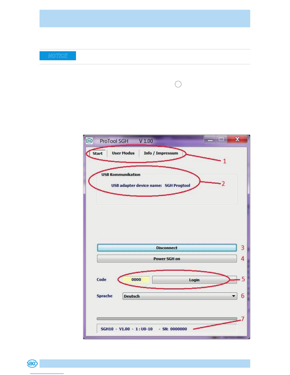
“Start” Tab
NOTICE
Page 21
ProTool SGH
Functional description English
ProTool SGH · Date 04.09.2018 · Art. No. 89757 · Mod. status 300/18
21
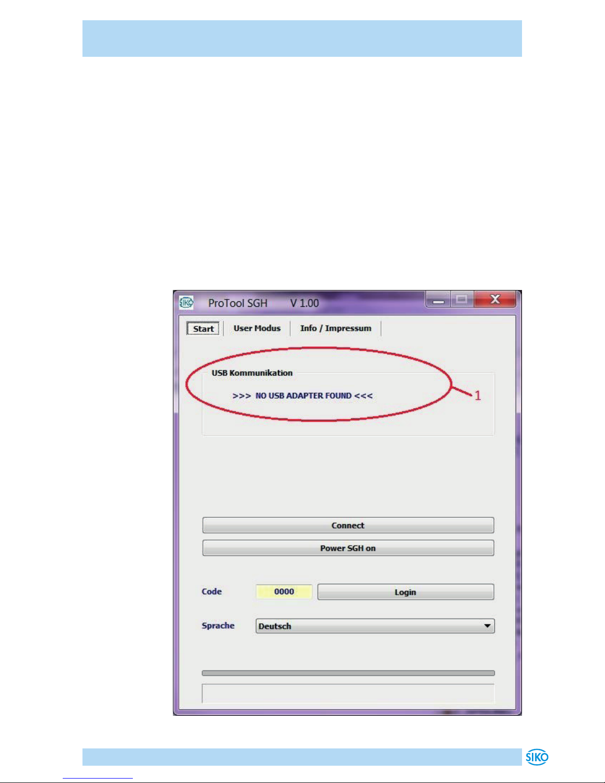
Nr. Description / function Comment
1 Tab: Switch with mouse click
2 Status information about the commu-
nication via USB between PC and SGH
Pro-Tool
Here error-free
3 Switch USB communication on/o
4 Switch the operating voltage on/off
(24 V DC) for the SGHXX
5 For factory use only
6 Language selection (German/Eng-
lish)
7 Status information of the connected
SGHXX: Type, type of output circuit,
serial number
Only for USB communication and power on
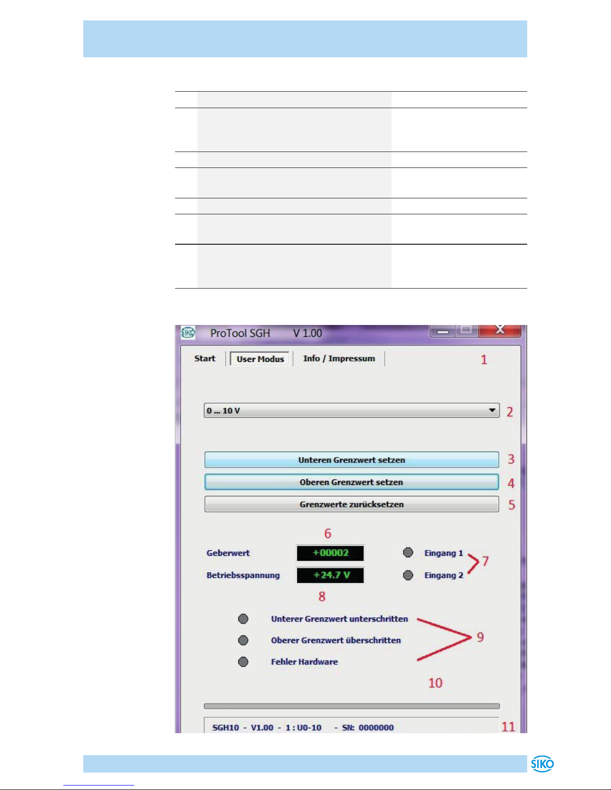
"User Mode" Tab
Page 22
ProTool SGH
Functional description English
ProTool SGH · Date 04.09.2018 · Art. No. 89757 · Mod. status 300/18
22
Nr. Description / function Comment
1 Tab: Switch with mouse click
2 Parameterize analog output
type
Not at CAN output
3 Set lower limit value Not at CAN output (see chapter
4.2.)
4 Set upper limit value Not at CAN output (see chapter
4.2 Limit Value Adjustment)
5 Reset limit values Not at CAN output (see chapter
4.2)
6 Encoder value output (without
taking into account the limit
values)
7 Status display of the external
inputs Lim 2 & LIM 2
Not at CAN output
8 Operating voltage of the SGHXX
(approx. 24 V DC powered from
the USB interface)
9 Limit value and error status Not at CAN output
10 Sensor value as bar represen-
tation; green within the limit
values; red when limit value
exceeded or fallen below.
11 Status information of the con-
nected SGHXX: Type, type of
output circuit, serial number
Only for USB communication and
power on
4.2 Limit value adjustment: (analog output only)
Adjust the lower limit value:
• Move the SGHXX to the position where the minimum analog value
(e.g., I 4-20 mA; 4 mA) is to be output by pulling out the wire (cylinder).
• Press the LIM 1 button for >3 seconds.
Alternative
• Press the “Set lower limit” button in the software.
• The encoder then outputs its minimum value (depending on the type
of output).
Page 23
ProTool SGH
Functional description English
ProTool SGH · Date 04.09.2018 · Art. No. 89757 · Mod. status 300/18
23
Adjust the upper limit value:
• Move the SGHXX to the position where the maximum analog value
(e.g., I 4-20 mA; 20 mA) is to be output by pulling out the wire (cylinder).
• Press the LIM 1 button for >3 seconds.
Alternative
• Press the “Set upper limit” button in the software.
• The encoder then outputs its maximum value (depending on the type
of output).
4.3 Error Description
Page 24
ProTool SGH
Technical data English
ProTool SGH · Date 04.09.2018 · Art. No. 89757 · Mod. status 300/18
24
Nr. Description / function Comment
1 No USB-communication - USB-driver not installed
- ProTool SGH not connected with PC
2 No status information - Communication with the SGHXX is
switched o
5 Technical data
Mechanical data Additional information
Housing plastic
Color Agate gray, sky blue
Cable length 1.8 m USB 2.0 A connector - USB 2.0
Mini-B connector
0.3 m 8-pol. flat connector to the
encoder
Electrical data Additional information
Operating voltage via USB
Type of connection USB 2.0, Mini-B bushing
flat connector 8-pole bushing
Laboratory bushing 2
pieces ø4 mm
Current output/voltage output
Ambient conditions Additional information
Ambient temperature 0 ... 40 °C
Protection category IP20
Page 25
ProTool SGH
25
Page 26
ProTool SGH
26
Page 27
ProTool SGH
27
Page 28

SIKO GmbH
Weihermattenweg 2
79256 Buchenbach
Telefon/Phone
+ 49 7661 394-0
Telefax/Fax
+ 49 7661 394-388
Änderungen vorbehalten · Subject to technical alternations · 04.09.2018 · 300/18
 Loading...