

Page 1
Benutzerinformation
MSA511 + MBA511
Magnetsensor, Magnetband
DEUTSCH
1. Gewährleistungshinweise
Lesen Sie vor der Montage und der Inbetriebnahme
•
dieses Dokument sorgfältig durch. Beachten Sie zu
Ihrer eigenen Sicherheit und der Betriebssicherheit
alle Warnungen und Hinweise.
Ihr Produkt hat unser Werk in geprüftem und be-
•
triebsbereitem Zustand verlassen. Für den Betrieb
gelten die angegeben Spezifikationen und die
Angaben auf dem Typenschild als Bedingung.
Garantieansprüche gelten nur für Produkte der
•
Firma SIKO GmbH. Bei dem Einsatz in Verbindung
mit Fremdprodukten besteht für das Gesamtsystem
kein Garantieanspruch.
Reparaturen dürfen nur im Werk vorgenommen
•
werden. Für weitere Fragen steht Ihnen die Firma
SIKO GmbH gerne zur Verfügung.
2. Identifikation
Das Typenschild zeigt den Gerätetyp mit Variantennummer. Die Lieferpapiere ordnen jeder Variantennummer eine detaillierte Bestellbezeichnung zu.
z.B. MSA511-0023
Varianten-Nr.
Geräte-Typ
3. Mechanische Montage
Die Montage darf nur gemäß der angegebenen IPSchutzart vorgenommen werden. Das System muss
ggfs. zusätzlich gegen schädliche Umwelteinflüsse, wie z.B. Spritzwasser, Staub, Schläge, Tempe-
MSA511+MBA511 Datum 15.02.2010 Art.Nr. 81105 Änd. Stand 48/10 1
ratur geschützt werden.
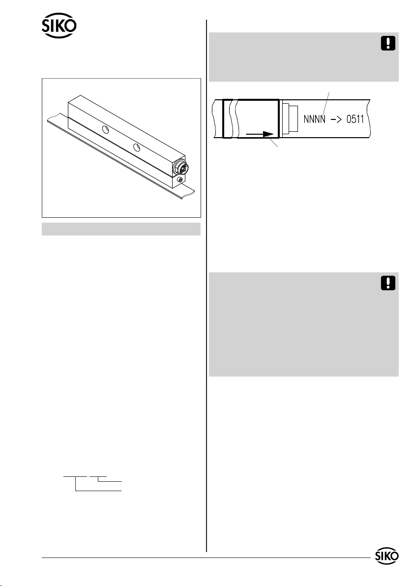
Achtung! Beachten Sie bei der Montage des Sensors oder des Magnetbandes die richtige Ausrichtung beider Systemkomponenten zueinander und
Einhaltung der Montagetoleranzen (siehe auch
Abb. 7).
Bedruckung auf Band
Bedruckung auf Sensor
Verfahrrichtung
Abb. 1: Ausrichtung
3.1 Montage Magnetband
Die Montage muss plan zur Montagefläche bzw.
der zu messenden Strecke erfolgen. Welligkeiten
verschlechtern immer die Messgenauigkeit. Es ist
für ausreichenden mechanischen Schutz zu sorgen
(z.B. gegen Schläge und Vibration).
Aus technischen Gründen muss bei der Länge,
gegenüber der Messstrecke, ein Zumaß von min.
178mm berücksichtigt werden.
Achtung! Um optimale Verklebungen zu erreichen müssen alle antiadhäsiven Fremdsubstanzen
(Öl, Fett, Staub usw.) durch möglichst rückstandslos verdunstende Reinigungsmittel entfernt werden. Als Reinigungsmittel eignen sich u.a. Ketone
(Aceton) oder Alkohole, die u.a. von den Firmen
Loctite und 3M als Schnellreiniger angeboten werden. Die Klebeflächen müssen trocken sein und es
ist mit höchstmöglichem Anpressdruck zu verkleben. Die Verklebungstemperatur ist optimal zwischen 20°C und 30°C in trockenen Räumen.
Tip! Bei Verklebung langer Bänder sollte die
Schutzfolie des Klebebandes über eine kurze Teilstrecke abgezogen werden, um das Band zu fixieren. Daraufhin erfolgt das Ausrichten des Bandes.
Nun kann über die restliche Länge die Schutzfolie,
unter gleichzeitigem Andruck des Bandes seitlich
herausgezogen werden (als Andruckhilfe kann z.B.
eine Tapetenandrückwalze verwendet werden).
Montageschritte (Abb. 2)
Befestigungsfläche (1) sorgfältig reinigen.
•
Am Magnetband die Schutzfolie (2) des Klebe-
•
bandes (3) entfernen.
Magnetband (4) unter Berücksichtigung der
•
Pfeilrichtung aufkleben.
Magnetbandoberfläche sorgfältig reinigen.
•
Page 2
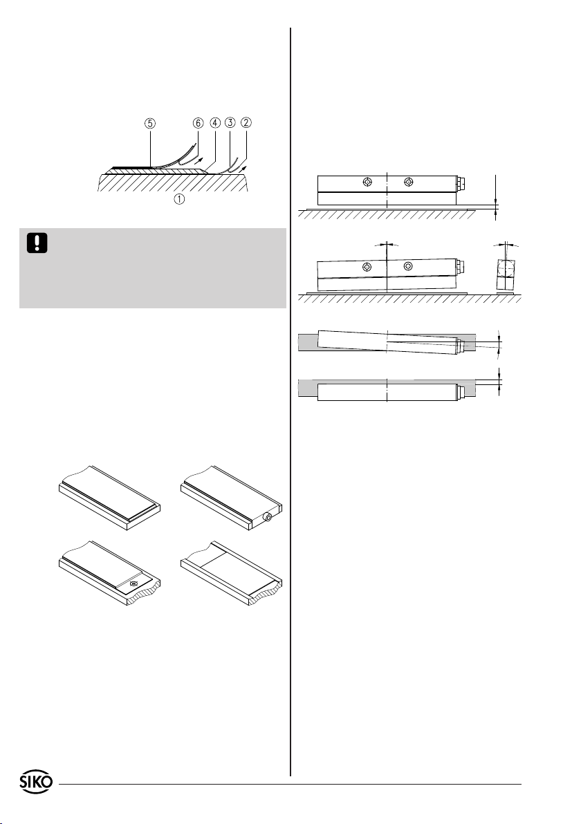
Am Abdeckband (5) die Schutzfolie (6) des Kle-
•
bebandes entfernen.
Abdeckband aufkleben (an beiden Enden leicht
•
überlappen lassen).
Die überlappenden Enden des Abdeckbandes gegen
•
Ablösen sichern.
Abb. 2: Montage Magnetband
Achtung! Die Beeinflussung durch magnetische
Felder ist zu vermeiden. Insbesondere dürfen keine Magnetfelder (z.B. Haftmagnete oder andere
Dauermagnete) in direkten Kontakt mit dem Magnetband geraten. Gleiches gilt für den Sensor im
Betrieb.
Montagebeispiele
Die einfache Montageart, durch angeschrägtes
Schutzband (Abb. 3), ist nur in sehr geschützter Umgebung zu empfehlen. Bei ungeschützer Umgebung
besteht Abschälgefahr. In solchen Fällen sind Montagearten, wie in Abb. 4 und 5 gezeigt, geeigneter.
Den optimalen Schutz bietet die Montage in einer Nut (Abb. 6), die so tief sein sollte, dass das
Magnetband vollständig darin eingebettet werden
kann (z.B. SIKO-PSA-Schiene).
Abb. 3 Abb. 4
Innerhalb der angegebenen Lageabweichung Abb.
7 ist der Messfehler vernachlässigbar.
Der maximale Abstand zwischen Sensor und
Band (ohne Abdeckband) beträgt 2mm. Bei
Verwendung eines Abdeckbandes reduziert sich
der eff. Abstand um die Dicke des Abdeckbandes inkl. Klebefolie. Der Sensor sollte das Magnetband nicht berühren.
Die Addition der Montagetolerenzen in allen Ebenen muss vermieden werden.
0.1 ... 2
<0.5°
<3°
<1°±1.0
Abb. 7: Montagetoleranzen
4. Elektrischer Anschluss
Anschlussverbindungen dürfen nicht unter
•
Spannung geschlossen oder gelöst werden!!
Verdrahtungsarbeiten dürfen nur spannungslos
•
erfolgen.
Litzen sind mit Aderendhülsen zu versehen.
•
Vor dem Einschalten sind alle Leitungsanschlüsse
•
und Steckverbindungen zu überprüfen.
Hinweise zur Störsicherheit
Alle Anschlüsse sind gegen äußere Störeinflüsse
Abb. 5 Abb. 6
3.2 Montage Sensor
Bei der Montage des Sensors ist unbedingt darauf
zu achten, dass die Pfeilrichtung des Sensoraufdruckes mit der Pfeilrichtung des Bandaufdruckes
übereinstimmt (Abb. 1).
Die Lage des Sensors zum Magnetband ist genau
definiert. Bei der Montage ist insbesondere zu beachten, dass über die gesamte Messstrecke zwischen Band und Sensor ein Luftspalt eingehalten
wird, unabhängig ob das Band oder der Sensor
bewegt werden (Abb. 7).
2 MSA511+MBA511 Datum 15.02.2010 Art.Nr. 81105 Änd. Stand 48/10
geschützt. Der Einsatzort ist aber so zu wählen,
dass induktive oder kapazitive Störungen nicht
auf den Geber oder deren Anschlussleitungen
einwirken können! Durch geeignete Kabelfüh-
rung und Verdrahtung können Störeinflüsse (z.B.
von Schaltnetzteilen, Motoren, getakteten Reglern oder Schützen) vermindert werden.
Erforderliche Maßnahmen:
Nur geschirmtes Kabel verwenden. Den Kabel-
•
schirm beidseitig auflegen. Litzenquerschnitt der
Leitungen 0,25mm2.
Die Verdrahtung von Abschirmung und Masse
•
Page 3
(GND) muss sternförmig und großflächig erfolgen.
Der Anschluss der Abschirmung an den Potentialausgleich muss großflächig (niederimpedant)
erfolgen.
Das System muss in möglichst großem Abstand von
•
Leitungen eingebaut werden, die mit Störungen
belastet sind; ggfs. sind zusätzliche Maßnahmen
wie Schirmbleche oder metallisierte Gehäuse
vorzusehen. Leitungsführungen parallel zu Energieleitungen sind zu vermeiden.
Schützspulen müssen mit Funkenlöschgliedern
•
beschaltet sein.
Spannungsversorgung: 24 VDC -20% ... +20%
Leistungsaufnahme: < 3 Watt
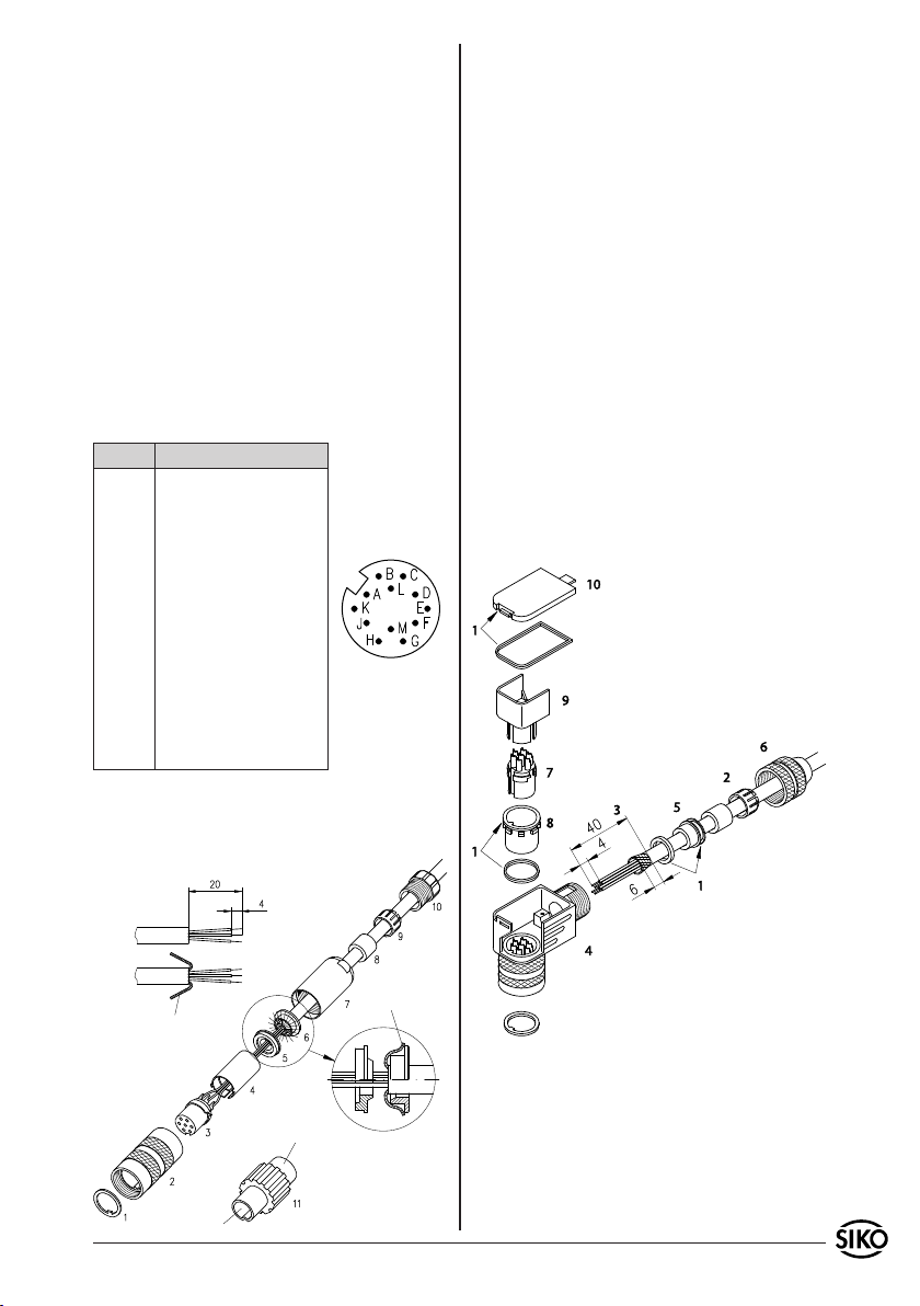
4.1 Anschlussbelegung (Kabellänge max. 100m)
12-pol. Stiftkontakt:
Pin Belegung
A SSI DatenB SSI Daten+
C SSI TaktD SSI Takt+
E +24VDC
F Sinus
G RS485 DÜA
H RS485 DÜB
J GND
Ansichtseite =
Steckseite
K N.C.
L Nullungseingang
M Cosinus
4.2 Anschlussstecker
12-pol. Gegenstecker gerade
Bei SIKO als Zubehör unter Art.Nr. 76572 erhältlich.
Pos. 6 ... 10 über Kabelmantel schieben.
1.
Kabel abisolieren.
2.
Schirm umlegen.
3.
Pos. 5 auf Litzen schieben.
4.
Litzen an Pos. 3 löten (entspr. Anschluss-
5.
plan).
Abstandhülse Pos. 4 aufweiten und über Litzen
6.
stülpen, zusammendrücken und auf Pos. 3 stecken. Schlitz und Nut (Pos. 3 und 4) müssen
deckungsgleich sein.
Pos. 6 an Pos. 5 drücken, überstehenden Schirm
7.
abschneiden.
Pos. 2 und 7 aufschieben und mittels Montage-
8.
werkzeug Pos. 11 verschrauben.
Pos. 8 in Pos. 9 stecken, beides in Pos. 7
9.
schieben.
Pos. 10 mit Pos. 7 verschrauben.
10.
Pos. 1 in Pos 2. schieben.
11.
12-pol. Gegenstecker winkel
Bei SIKO als Zubehör unter Art.Nr. 79666 erhältlich.
Schirm
Schirm
Gehen Sie schrittweise vor:
Dichtungen montieren (3x).
1.
Kabelteile auffädeln.
Buchsenteil
Stiftteil
MSA511+MBA511 Datum 15.02.2010 Art.Nr. 81105 Änd. Stand 48/10 3
2.
Kabel und Schirm abmanteln.
3.
Litzen durch das Gehäuse fädeln.
4.
Schirmring, Klemmkorb montieren.
5.
Druckschraube leicht andrehen.
6.
Page 4
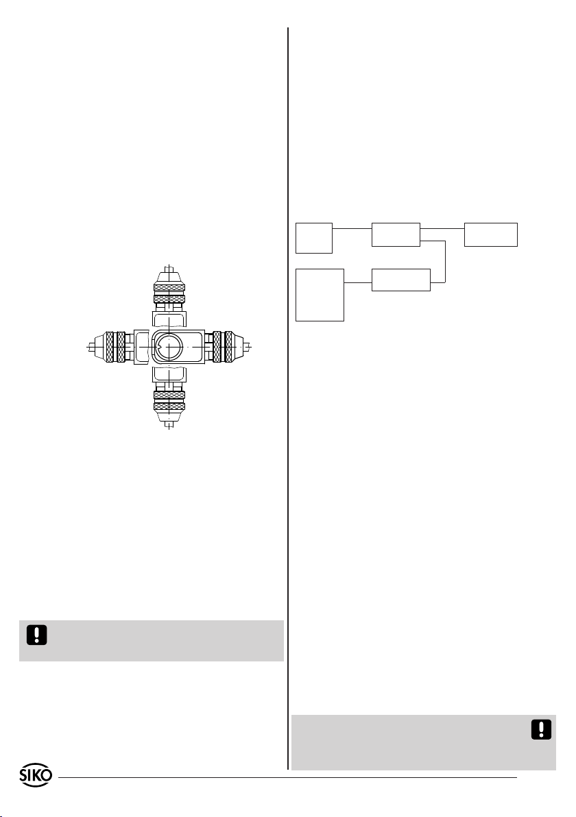
Litzen an Kontakteinsatz löten.
7.
Verdrehhülse in gewünschte Winkelstellung (Lage
8.
der Nase beachten) montieren (90°-Schritte,
siehe auch Kap. "Ändern der Winkelstellung").
Kontakteinsatz, Distanzhülse einsetzen.
9.
Deckel einhaken.
10.
Druckschraube festziehen (ca. 10-20 Nm).
11.
Ändern der Winkelstellung:
Druckschraube (6) leicht aufdrehen.
1.
Deckel (10) und Distanzhülse (9) entfernen.
2.
Kontakteinsatz (7) und Verdrehhülse (8) in
3.
gewünschte Winkelstellung (90° Schritte)
verdrehen.
Distanzhülse, Deckel und Druckschraube mon-
4.
tieren.
grammierung beginnen, indem Sie:
ein geeignetes Terminalprogramm (z.B. sikoterm.
•
exe) starten und Ihre Befehle gemäß der Tabelle
"Befehlsliste – Servicebetrieb MSA511" manuell
eingeben (siehe Kapitel 7). Berücksichtigen Sie
die vorgegebenen Schnittstellenparameter.
Das Programm "sikoterm.exe" können Sie bei SIKO
anfordern oder in ihrer aktuellsten Version aus
dem Internet abrufen unter der Adresse:
http://www.siko.de/download
5.2 Applikationsbeispiel zur Sensorprogrammie-
rung und visuelle Positionswertdarstellung
Netzteil:
24 VDC/
500mA
PC
+24V/GND
RS232
RXD/TXD/GND
Pegelwandler
RS232 <-> RS485
MSA511
Takt+/Takt-/
Daten+/Daten-
RS485
DÜA/DÜB/GND
z.B. MA10/3
SSI
Abb. 9: Konfiguration der SIKO Messanzeige MA10/3
SSI: Datenformat: no, Geberbits: 24, Singleturnbits:
unrelevant, Ausgabecode: Gray
Konfiguration der SIKO-Messanzeige MA10/4 SSI:
Gebertyp: linear; Geberbits: 24; Faktor: 1.0 (1/100mm
Anzeige); Ausgabecode: Gray
5.3 SSI-Schnittstelle des Sensors
5. Inbetriebnahme
Nach Montage von Band und Sensor und vollständiger Verdrahtung kann das System in Betrieb genommen werden. Der Sensor wurde werksseitig auf
das Band abgeglichen.
5.1 Programmierung des Sensors
Der MSA511 kann über die integrierte RS485
Schnittstelle an die Bedürfnisse angepasst werden. Hierfür haben Sie die Möglichkeit einige
spezifische Parameter zu programmieren, die dann
nichtflüchtig gespeichert werden aber jederzeit
geändert werden können.
Wird die RS485-Schnittstelle nicht benutzt, sollten die Signale DÜA und DÜB aus störtechnischen
Gründen an GND angeschlossen werden.
Gehen Sie wie folgt vor:
Stellen Sie über einen Pegelwandler (z.B. Fa. Spectra Typ I-7520) eine Verbindung zwischen der seriellen RS232 Schnittstelle Ihres PC´s und der RS485
Schnittstelle des Sensors her.
Nachdem die Stromversorgung des Sensors eingeschaltet wurde, können Sie sofort mit der Pro-
4 MSA511+MBA511 Datum 15.02.2010 Art.Nr. 81105 Änd. Stand 48/10
Die integrierte SSI-Schnittstelle des MSA511 ermöglicht eine synchrone Ausgabe des Positionswertes. Dessen Datenformat umfasst eine Breite
von 24Bit, die im Graycode (siehe Kapitel 7)
rechtsbündig ausgegeben werden. Alle nachfolgenden Bits (25, 26...) werden mit "0" ausgegeben.
Die Datensignale entsprechen der RS422. Die Takteingänge sind optoentkoppelt und entsprechen
ebenfalls der RS422. Die SSI Monoflopzeit beträgt
typ. 20...25µs, daraus ergibt sich die minimale
Taktrate von 62,5kHz.
Leitungslänge 2m : max. Taktrate 1MHz
Leitungslänge 10m : max. Taktrate 800kHz
Leitungslänge 100m : max. Taktrate 250kHz
Leitungslänge 200m : max. Taktrate 125kHz
Zu beachten ist, dass die mögliche max. Taktrate
und Datensicherheit stark von der Länge der Anschlussleitung abhängt.
Falls die integrierte SSI-Schnittstelle nicht verwendet wird, sollten aus störtechnischen Gründen
die SSI-Eingangssignale Takt+ und Takt- an GND
angeschlossen werden.
Page 5
5.4 Sinus-/Cosinus-Ausgang
Der MSA511 stellt einen Sinus und Cosinus Ausgang zur Verfügung.
Periodenlänge : 5mm
Amplitude : 1Vss
Gleichspannungsanteil : 2,5V
Impedanz : 100Ω
5.5 Nullung
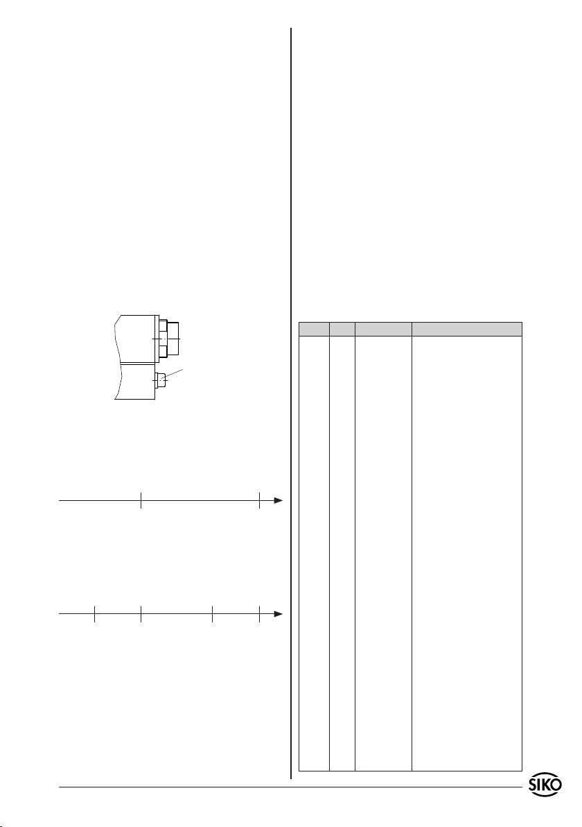
Der Sensor kann auf drei Arten genullt werden:
Aktivieren des Nullungseinganges (siehe Kapitel
1.
4.1) mit +24VDC (länger als 2 Sekunden).
Schnittstellenbefehl "l" (siehe Kapitel 7).
2.
Verwendung der Nullungsschraube. Zylinder-
3.
kopfschraube mit einem Sechskantstiftschlüssel
(SW2,5) bis zum spürbaren Anschlag herausdrehen. Nach ca. 1 Sekunde die Schraube
wieder ganz eindrehen, damit die Dichtwirkung
gegeben ist.
Nullungsschraube
5.6 Messbereich
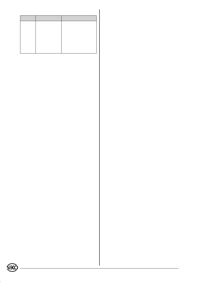
Bandkodierung:
Die absolute Kodierung des MBA511 erlaubt einen
max. Messbereich von 20480mm.
0 0
+20479999 +1 +20479999 +1
Positionswert (-480,000 ... +20.000mm)
Damit an der Position 0 keine Sprünge um den Maximalwert auftreten, wird dieser Maximalwert auf
20m begrenzt. Dadurch kann in negativer Verfahrrichtung ein Bereich bis -480mm erfasst werden.
0 0
+1999999 -48000 +1999999 -48000
-1 +1 -1 +1
6. Fehlerbehandlung
Typische Fehler, die bei Anbau und Betrieb auftreten können:
Der Sensor ist nicht, oder nicht korrekt ange-
•
schlossen (Pinbelegung siehe Kapitel 4).
Die Abstandstoleranz zwischen Sensor/Band
•
wurde nicht eingehalten (über die gesamte
Messstrecke!) oder der Sensor streift auf dem
Magnetband (siehe Abb. 7).
Kabelunterbrechung / Abtrennung durch scharfe
•
Kanten/Quetschung.
Der Sensor ist mit der aktiven Seite vom Band
•
abgewandt montiert (siehe Abb. 8).
Sensor und Band sind zueinander falsch ausge-
•
richtet (siehe Kapitel 1).
Magnetische Felder in unmittelbarer Nähe der
•
Messfläche verfälschen die Messwerte, ggf. sind
Maßnahmen zur Abschirmung nötig.
Falsche Messwerte infolge EMV Störungen (siehe
•
Kapitel 4).
7. Befehlsliste Servicemode
Parameter: 19200 Baud, kein Parity, 8Bit, 1
Ausgabe: ASCII / Hexadezimal
Wertebereiche: 2/3 Byte: 0...65535 / 0...± 2
Alle Ausgaben, die eine Bestätigung ">" beinhalten,
werden mit einem "CR" (Dez 13) abgeschlossen.
Befehl Länge Antwort Beschreibung
a 1/13 "MSA511V1.00>" Gerätetyp/Softwarekennung
b 1/4 "ba3f" 2x2 Byte Analog-Wandlerwerte
cxy 3/4 "xy>" EEPROM-Werte auslesen
dxyabcd 7/2 ">" EEPROM-Werte speichern
g 1/8 "a3170216" 2 Byte Offset-0;
k 1/0 "" Software-RESET
l11100 6/2 ">" Gerät nullen (Positionswert auf
p11100 6/2 ">" Abgleich starten
q 1/2 "31" 1. Byte = Mode;
s11100 6/2 ">" Gerät auf default-Werte setzen;
tx 1/2 ">" Zählrichtung setzen
u 1/5 "abc" a = quadrant (0 oder 1);
yx 2/10 "+abcdefg>" x=0: Feinwert
z 1/10 "+abcdefg>" Positionswert
Stopbit, ohne Handshake
(4 Byte)
xy = Adresse 00 ... 63 Rückgabewert 2 Byte Hexadezimal
xy = Adresse 00 ... 06 abcd 2
Byte-Wert Hexadezimal
2 Byte Offset-1;
2 Byte Ink-Gap;
2 Byte Abs-Nullwert
Null setzen)
2. Byte = Abgleichflag
Abgleich wird gelöscht!
default-Werte:
Zählrichtung = auf
(in Verfahrrichtung steigende
Werte, siehe Abb.1)
Nullpunktwert = 0
x=0: normal
x=1: invers
b = Pol1-Sensor (0 oder 1);
c = Pol2-Sensor (0 oder 1)
x=1: Grobwert
x=2: abs-wert-0
x=3: abs-wert-1
x=4: Positionswert
23
MSA511+MBA511 Datum 15.02.2010 Art.Nr. 81105 Änd. Stand 48/10 5
Page 6
EEPROM Speicherbelegung:
Adresse Größe in Word Belegung
0 1 Offset-0
1 1 Offset-1
2 1 Ink-Gap
3 1 Abs-null-wert
4 - 5 2 Nullungswert (Long)
6 1 Zählrichtung
6 MSA511+MBA511 Datum 15.02.2010 Art.Nr. 81105 Änd. Stand 48/10
Page 7
User Information
MSA511 + MBA511
Magnetic Sensor and Strip
ENGLISH
1. Warranty information
In order to carry out installation correctly, we
•
strongly recommend this document is read very
carefully. This will ensure your own safety and
the operating reliability of the device.
Your device has been quality controlled, tested
•
and is ready for use. Please observe all warnings
and information which are marked either directly
on the device or specified in this document.
Warranty can only be claimed for components
•
supplied by SIKO GmbH. If the system is used
together with other products, there is no warranty
for the complete system.
Repairs should be carried out only at our works.
•
If any information is missing or unclear, please
contact the SIKO sales staff.
2. Identification
Please check the particular type of unit and type
number from the identification plate. Type number
and the corresponding version are indicated in the
delivery documentation.
e.g. MSA511-0023
version number
type of unit
3. Installation
For mounting, the degree of protection specified
must be observed. Protect the unit, if necessary,
against environmental influences such as sprayed
MSA511+MBA511 Datum 15.02.2010 Art.Nr. 81105 Änd. Stand 48/10 7
water, dust, knocks, extreme temperatures.
Attention! When mounting sensor and magnetic
strip please observe that both components are
correctly aligned and that the mounting tolerances are respected (see fig. 7).
Marking on strip
Marking of sensor
Travel direction
Fig. 1: Alignment
3.1 Mounting the magnetic strip
The mounting surface/measuring track must be
flat. Buckles or bumps will lead to inaccurate
measurement results. Please protect the magnetic
strip from mechanical damage (e.g. against shocks
and vibration).
For technical reasons the strip should be min.
178mm longer than the actual measuring distance.
Attention! To guarantee optimal adhesion oil,
grease dust etc. must be removed by using cleansing agents which evaporate without leaving residues. Suitable cleansing agents are eg. ketones
(acetone) or alcohols; the companies Loctite and
3M can both supply such cleaning liquid. Make
sure that the surface to be glued is dry and apply
the strip with maximum pressure. Glueing should
preferably be carried out at temperatures between
20°C to 30°C and in dry atmosphere.
Advice! When applying long pieces of magnetic
strip do not immediately remove the complete
protective foil, but rather peel back a short part
from the end sufficient to fix the strip. Now align
the strip. As the protective strip is then peeled
back and out press the tape firmly onto the mounting surface. A wall paper roller wheel could be
used to assist in applying pressure onto the magnetic strip when fixing it in position.
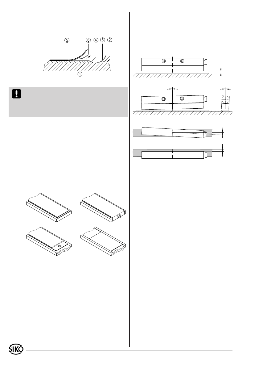
Mounting steps (fig. 2)
Carefully clean the mounting surface (1)
•
Remove protective foil (2) from the adhesive side
•
of the magnetic tape (3).
Stick down the magnetic strip (4) while ensuring
•
correct alignment.
Carefully clean the surface of the magnetic strip.
•
Remove protective foil (6) from adhesive tape on
•
the cover strip (5).
Page 8
Fix cover strip (both ends should slightly over-
•
lap).
Also fix cover strip's ends to avoid unintentional
•
peeling.
and magnetic strip (without cover strip) is
2mm. When using a cover strip, the gap is reduced by the thickness of the cover strip including its adhesive tape. The Sensor must not
touch the magnetic strip.
An accumulation of the different possible mounting tolerances should be avoided.
0.1 ... 2
Fig. 2: Mounting the magnetic strip
Attention! Do not expose the magnetic strip to
magnetic fields. Any direct contact of the magnetic
strip with magnetic fields (e.g. adhesive magnets
or other permanent magnets) is to be avoided. The
same applies to the sensor during operation.
Mounting examples
Mounting with chamfered ends (fig. 3) is not recommended unless the strip is installed in a safe
and protected place without environmental influences. In less protected mounting locations the
strip may peel. There we recommend mounting
accord. to fig. 4 and fig. 5.
Mounting in a groove (fig. 6) best protects the
magnetic strip. The groove should be deep enough
to totally embed the magnetic strip (e.g. SIKOPSA-rail).
Fig. 3 Fig. 4
Fig. 5 Fig. 6
3.2 Sensor mounting
When mounting the magnetic sensor, ensure that
the arrow on the sensor heads in the same direction as the arrows on the magnetic strip (fig. 1).
The sensor's position relative to the magnetic strip
is exactly defined. The correct gap between sensor and magnetic strip must be maintained over
the total travel distance, irrespective whether the
strip or sensor moves (fig. 7).
Within the defined limits (fig. 7), errors due to
deviation are less important than errors resulting
from strip and sensor tolerances.
The max. allowable distance between sensor
<0.5°
<3°
<1°±1.0
Fig. 7: Mounting tolerances
4. Electrical connection
Switch power off before any plug is inserted
•
or removed!!
Wiring must only be carried out with power off.
•
Provide standed wires with ferrules.
•
Check all lines and connections before switching
•
on the equipment.
Interference and distortion
All connections are protected against the effects
of interference. The location should be selected
to ensure that no capacitive or inductive interferences can affect the encoder or the connection lines! Suitable wiring layout and choice
of cable can minimise the effects of interference
(e.g. interference caused by SMPS, motors, cyclic
controls and contactors).
Necessary measures:
Only screened cable should be used. Screen should
•
be connected to earth at both ends. Cross section
of the lines = 0,25 mm2.
Wiring to screen and to ground (0V) must be via
•
a good earth point having a large surface area
for minimum impedance.
The unit should be positioned well away from
•
cables with interference; if necessary a protective
8 MSA511+MBA511 Datum 15.02.2010 Art.Nr. 81105 Änd. Stand 48/10
Page 9
screen or metal housing must be provided. The
running of wiring parallel to the mains supply
should be avoided.
Contactor coils must be linked with spark sup-
•
pression.
Power supply: 24 VDC -20% ... +20%
Power consumption: < 3 Watt
4.1 Connection type (cable length max. 100m)
12 pole plug pin:
Pin Designation
A SSI DataB SSI Data+
C SSI CycleD SSI Cycle+
E +24VDC
F sinus
G RS485 DÜA
H RS485 DÜB
J GND
viewing side =
plug-in side
K N.C.
L zero-setting entry
M cosinus
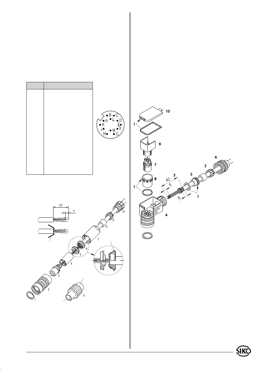
4.2 Connector
12-pole mating connector straight
Available from SIKO as accessory art. no. 76572.
Open spacer (part 4) and put it over ferrules,
6.
squeeze and push it onto part 3. Slot and keyway
of parts 3 and 4 must align.
Press parts 6 and 5 together; cut prodruding
7.
screening.
Push parts 2 and 7 together and screw
8.
part 11 using appropriate tool.
9.
Push part 8 into part 9 and slide both parts
10.
into part 7.
Screw parts 10 and 7 together.
11.
Push part 1 into part 2.
12.
12-pole mating connector angle
Available from SIKO as accessory art. no. 79666.
screening
socket
pin
Slip parts 6 to 10 over outer cable.
1.
Strip cable.
2.
Turn down screening.
3.
Push part 5 onto ferrules.
4.
Solder stranded wires at part 3 (follow connec-
5.
screening
tion diagram).
MSA511+MBA511 Datum 15.02.2010 Art.Nr. 81105 Änd. Stand 48/10 9
Please proceed as follows:
Mount seals (3x).
1.
Stringing cable parts.
2.
Dismantle cable and shield.
3.
Thread-up wires through the housing.
4.
Mount shielding ring and pinch ring.
5.
Turn on the pressing screw very slightly.
6.
Solder wires on insert.
7.
Adjust the turnable shell inside the connector to
8.
the required angular position (ensure position of
the stud) in steps of 90° (see chapter "Changing
the angle position").
Set in insert and distance sleeve.
9.
Mount cover.
10.
Fix pressing screw (approx. 10-20 Nm).
11.
Page 10
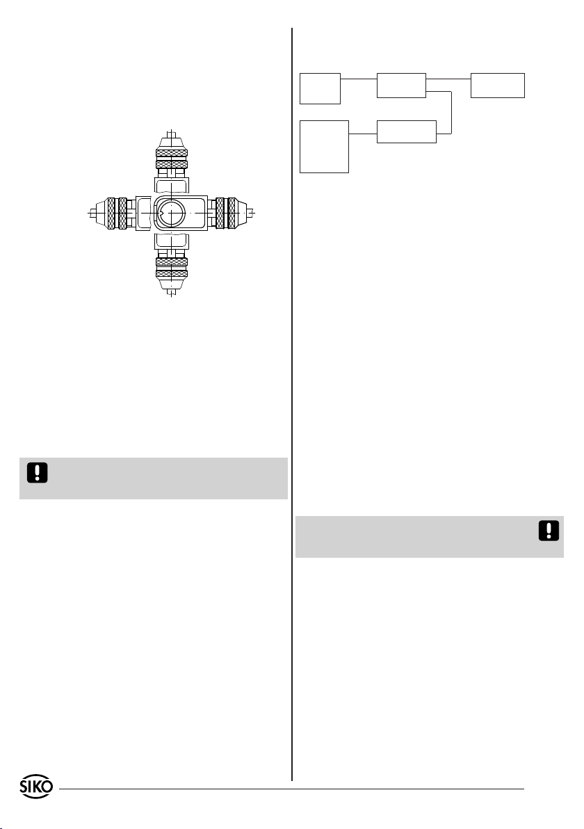
Changing the angle position:
Slightly unscrew screw (6).
1.
Remove cap (10) and distance sleeve (9).
2.
Adjust the contacts (7) and the shell (8) to the
3.
desired angular position (in 90° steps).
Mount distance sleeve, cap and screw.
4.
5. Commissioning
After mounting tape and sensor and after correct
wiring, the system is ready for use. Alignment of
sensor and tape is carried out by the manufacturer
before the material leaves the factory.
5.1 Sensor programming
Certain parameters of sensor MSA511 are programmable via its RS485 interface and are non volatile,
but can nevertheless be modified at any time.
If interface RS485 is not used, signals DÜA and
DÜB should be connected to GND to avoid interference.
Please proceed as follows:
Use a level converter (eg. type I-7520 from Spectra company) to establish a connection between
your PC's serial RS232 interface and the sensor's
RS485 interface.
Switch on the sensor's power supply and start with
programming by:
using a suitable terminal program (eg. sikoterm.
•
exe) and by manually entering your commands
accord. to the table "list of commands – service
operation of MSA511" (see chapter 7). Please
remember that your terminal has to be adjusted to
the pre-programmed interface parameters.
Please ask SIKO for software "sikoterm.exe" or
download it from our website - address:
http://www.siko.de/download
5.2 Application examples for sensor programming
and display of the position value
power pack:
24VDC/
500mA
PC
+24V/GND
RS232
RXD/TXD/GND
level converter
RS232 <-> RS485
MSA511
cycle+/cycle-/
data+/data-
RS485
DÜA/DÜB/GND
eg. MA10/3
SSI
Fig. 9: Programming of SIKO display MA10/3 SSI:
Data format: no; encoder bits: 24; singleturnbits:
irrelevant; output code: Gray
Programming of SIKO display MA10/4 SSI: encoder
type: linear; encoder bits: 24; factor: 1.0 (1/100mm
display); output code: Gray
5.3 Sensor's SSI-interface
MSA511's SSI-interface allows a synchronuous
output of the position value. Its data format comprises a width of 24 bit which are either issued as
Gray codes (see chapter 7) and right-aligned. All
following bits (25, 26...) are issued as "0".
Data signals correspond to RS422. Cycle inputs are
opto-decoupled and also correspond to RS422. Typical SSI monoflop time is. 20...25µs which gives
a min. cycle rate of 62,5kHz.
Cable length 2m : max. cycle rate 1MHz
Cable length 10m : max. cycle rate 800kHz
Cable length 100m : max. cycle rate 250kHz
Cable length 200m : max. cycle rate 125kHz
Please note that the possible max. cycle rate and
data integrity mainly depend on the length of the
connection line.
If the integral SSI-interface is not used, SSI input
signals cycle+ and cycle- should be connected to
GND to avoid interference.
5.4 Sinus-/Cosinus Output
MSA511 has a sinus and cosinus output:
cycle duration : 5mm
amplitude : 1Vss
d.c. voltage component : 2,5V
impedance : 100Ω
5.5 Zero-Setting
There are three possibilities for zeroing the sensor:
Zeroing input (see chapter 4.1) can be activated
1.
with +24 VDC (for more than 2 seconds).
By interface command "I" (see chapter 7).
2.
By using a zero-setting screw, e.g. a cylinder
3.
10 MSA511+MBA511 Datum 15.02.2010 Art.Nr. 81105 Änd. Stand 48/10
Page 11
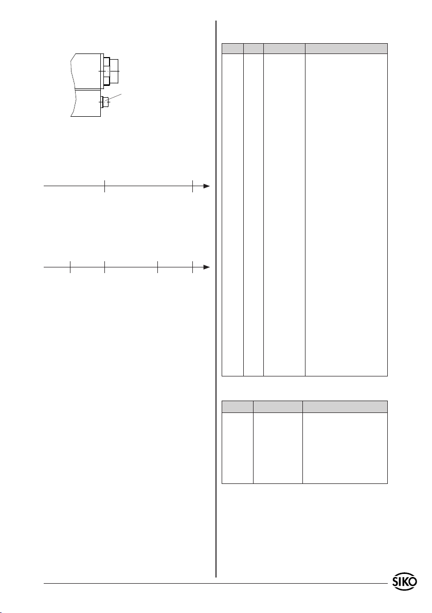
head stud (SW2,5) which must be screwed out
up to the stop and then, after approx. 1 second,
entirely screwed in to maintain tightness.
zero-setting screw
5.6 Measurement range
Band coding:
The absolute coding of MBA511 enables a max.
measurement range of 20480mm.
0 0
+20479999 +1 +20479999 +1
Position value (-480,00 ... +20.000mm)
In order to avoid leaps occurring around the maximum value at the 0 position, this maximum value
is limited to 20m. This enables recording of a range of up to -480mm in negative travel direction.
0 0
+1999999 -48000 +1999999 -48000
-1 +1 -1 +1
6. Trouble shooting
Below there are some typical errors which may occur during installation and operation:
Sensor not or incorrectly connected (for pin
•
connection see chapter 4).
Tolerance for the gap between magnetic sensor and
•
magnetic strip not observed over the total travel
distance. Sensor touches strip (see chapter 7).
Cable squeezed / interrupted / cut by sharp
•
edges.
Sensor's active side not mounted towards the
•
magnetic strip (see fig. 8).
Sensor and magnetic strip have been incorrectly
•
aligned (see chapter 1).
Magnetic fields near the measuring surface distort
•
the measuring values. If required, provide for
adequate screening.
Wrong measuring values due to EMC interferences
•
(see chapter 4).
All replies which are confirmed by ">" end with
"CR" (Dez 13).".
Com. Length Reply Description
a 1/13 "MSA511V1.00>" Device type/software version
b 1/4 "ba3f" 2x2 byte analogue converter
cxy 3/4 "xy>" Readout EEPROM values
dxyabcd 7/2 ">" Stores EEPROM values
g 1/8 "a3170216" 2 byte offset-0;
k 1/0 "" Software reset
l11100 6/2 ">" Zero-setting (position value is
p11100 6/2 ">" Starts alignment
q 1/2 "31" 1. byte = mode;
s11100 6/2 ">" Set device to default values;
tx 1/2 ">" Determine counting direction
u 1/5 "abc" a = quadrant (0 or 1);
yx 2/10 "+abcdefg>" x=0: fine value
z 1/10 "+abcdefg>" position value
values (4 byte)
xy = address 00 ... 63 value returned 2 byte hexadecimal
xy = address 00 ... 06 abcd 2
byte values hexadecimal
2 byte offset-1;
2 byte Ink-Gap;
2 byte absolute zero value
set to 0)
2. byte = alignment flag
Alignment will be cleared!
default values:
counting direction = up
(in travel direction, increasing
values; see fig. 1)
Zero point value = 0
x=0: up
x=1: down
b = Pol1-sensor (0 or 1);
c = Pol2-sensor (0 or 1)
x=1: rough value
x=2: absolute value 0
x=3: absolute value 1
x=4: position value
EEPROM memory array:
Address Size in words Assignment
0 1 offset-0
1 1 offset-1
2 1 ink-Gap
3 1 absolut-null-wert
4 - 5 2 zero setting value (Long)
6 1 counting direction
7. List of commands / service mode
Parameters: 19200 Baud, no parity, 8 bit, 1 stop
Data code: ASCII / Hexadecimal
Value range: 2/3 Byte: 0...65535 / 0...± 2
MSA511+MBA511 Datum 15.02.2010 Art.Nr. 81105 Änd. Stand 48/10 11
bit, no handshake
23
Page 12
SIKO GmbH
Werk / Factory:
Weihermattenweg 2
79256 Buchenbach-Unteribental
Postanschrift / Postal address:
Postfach 1106
79195 Kirchzarten
Telefon/Phone +49 7661 394-0
Telefax/Fax +49 7661 394-388
E-Mail [email protected]
Internet www.siko.de
Service [email protected]
12 MSA511+MBA511 Datum 15.02.2010 Art.Nr. 81105 Änd. Stand 48/10
 Loading...