

Page 1
Benutzerinformation
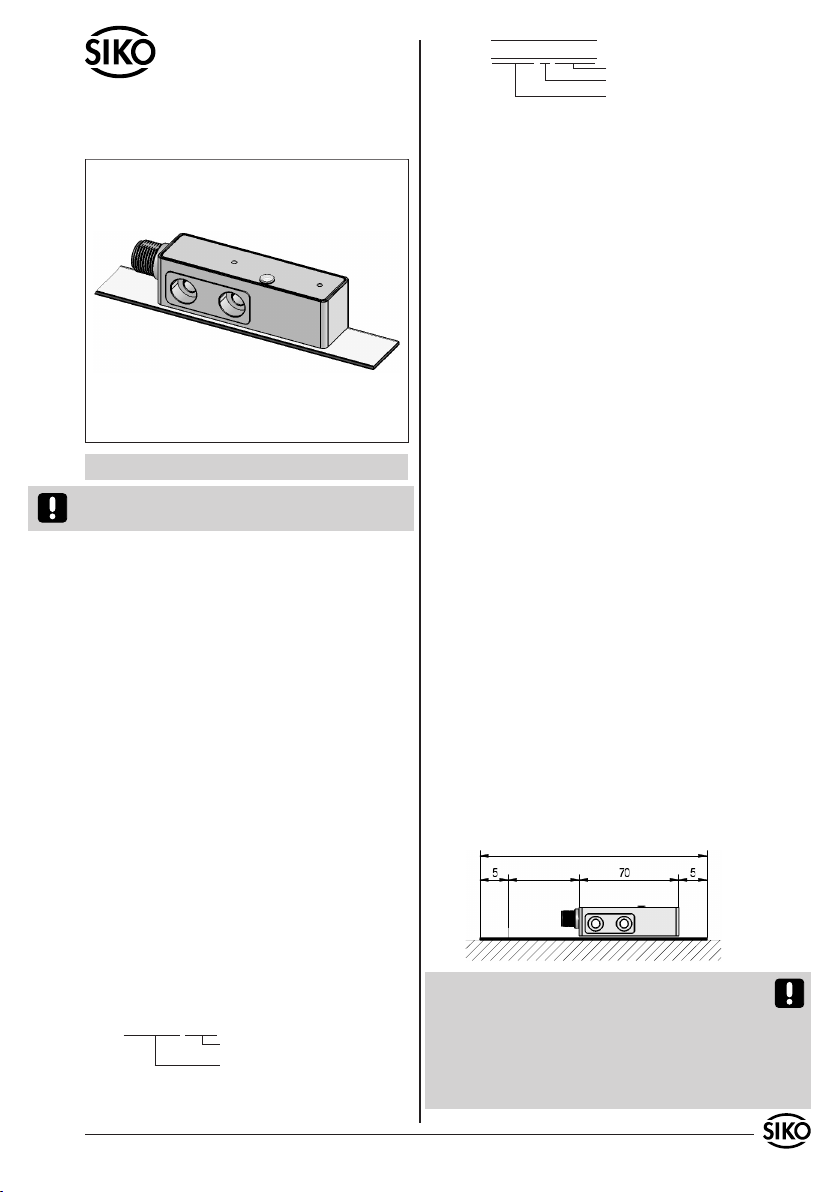
MSA501, MBA501
Magnetsensor, Magnetband
DEUTSCH
Sensordarstellungen sind exemplarisch und gültig
für alle Bauformen, sofern nicht gesondert beschrieben.
1. Gewährleistungshinweise
Lesen Sie vor der Montage und der Inbetriebnahme
•
dieses Dokument sorgfältig durch. Beachten Sie zu
Ihrer eigenen Sicherheit und der Betriebssicherheit
alle Warnungen und Hinweise.
Ihr Produkt hat unser Werk in geprüftem und be-
•
triebsbereitem Zustand verlassen. Für den Betrieb
gelten die angegeben Spezifikationen und die
Angaben auf dem Typenschild als Bedingung.
Garantieansprüche gelten nur für Produkte der
•
Firma SIKO GmbH. Bei dem Einsatz in Verbindung
mit Fremdprodukten besteht für das Gesamtsystem
kein Garantieanspruch.
Reparaturen dürfen nur im Werk vorgenommen
•
werden. Für weitere Fragen steht Ihnen die Firma
SIKO GmbH gerne zur Verfügung.
2. Identifikation
Magnetsensor: Das Typenschild zeigt den Ge-
rätetyp mit Variantennummer. Die Lieferpapiere
ordnen jeder Variantennummer eine detaillierte
Bestellbezeichnung zu.
z.B. MSA501-0023
Varianten-Nr.
Geräte-Typ
Magnetband: Das Magnetband ist durch eine fortlaufende Bedruckung identifizierbar.
MBAxxxx WT NNNNNN
Chargennummer
Werkstoff-Trägerband
MBA Typ
3. Kurzbeschreibung
Der Sensor erfasst die absolute Weginformation
des codierten Magnetbandes MBA501. Über die
Geberschnittstelle kann der absolute Positionswert mit einer Auflösung von 5µm (bzw. 10µm)
von einer übergeordneten Steuerung ausgelesen
werden. Optional steht zusätzlich eine Inkremental-Schnittstelle mit Quadratursignalen in unterschiedlichen Auflösungen zur Verfügung. Über
einen externen Eingang kann der Sensor in verschiedene Betriebsmodi versetzt werden (Parametrierung, Kalibrierwert setzen).
In der durch den externen Eingang "Config" eingstellten Servicemode-Betriebsart arbeitet die
Datenschnittstelle (D+, D-) im bidirektionalen
RS485-Mode. Mit Hilfe eines RS485/RS232-Protokollwandlers kann der Sensor an einen PC angeschlossen und über ein beliebiges Terminalprogramm gemäß dem definierten Befehlssatz
parametriert werden.
Zu Diagnosezwecken befindet sich an der Oberseite
des Sensors eine Zweifarben-LED, welche die Darstellung von Fehler- bzw. Status-Zuständen erlaubt.
4. Mechanische Montage
Die Montage darf nur gemäß der angegebenen IPSchutzart vorgenommen werden. Das System muss
ggfs. zusätzlich gegen schädliche Umwelteinflüsse, wie z.B. Spritzwasser, Staub, Schläge, Temperatur geschützt werden.
Montage Magnetband
Die Montage muss plan zur Montagefläche bzw. der
zu messenden Strecke erfolgen. Welligkeiten verschlechtern immer die Messgenauigkeit. Es ist für
ausreichenden mechanischen Schutz zu sorgen.
(z.B. gegen Schläge und Vibration).
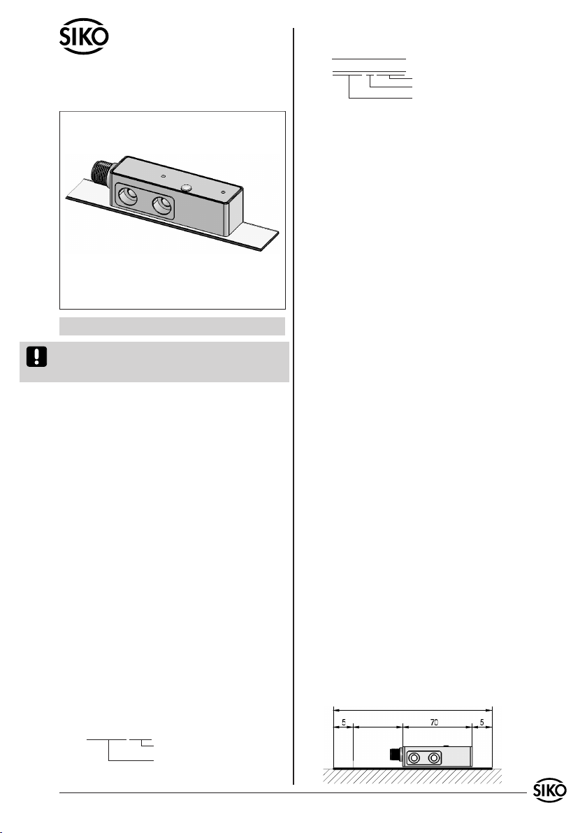
Aus technischen Gründen muss bei der Länge, gegenüber der Messstrecke, ein Zumaß von 80mm
berücksichtigt werden.
erf. Bandlänge = Messweg + 80mm (min. 200mm)
Messweg
MSA501, MBA501 Datum 14.12.2010 Art.Nr. 85613 Änd. Stand 449/10 1
Page 2
NNNNNN
Achtung! Um optimale Verklebungen zu erreichen
müssen alle antiadhäsiven Fremdsubstanzen (Öl,
Fett, Staub usw.) durch möglichst rückstandslos
verdunstende Reinigungsmittel entfernt werden.
Als Reinigungsmittel eignen sich u.a. Ketone (Aceton) oder Alkohole, die u.a. von den Firmen Loctite und 3M als Schnellreiniger angeboten werden.
Die Klebeflächen müssen trocken sein und es ist
mit höchstmöglichem Anpressdruck zu verkleben.
Die Verklebungstemperatur ist optimal zwischen
20°C und 30°C in trockenen Räumen.
Tip! Bei Verklebung langer Bänder sollte die
Schutzfolie des Klebebandes über eine kurze Teilstrecke abgezogen werden, um das Band zu fixieren. Daraufhin erfolgt das Ausrichten des Bandes.
Nun kann über die restliche Länge die Schutzfolie
unter gleichzeitigem Andruck des Bandes, seitlich
herausgezogen werden (als Andruckhilfe kann z.B.
eine Tapetenandrückwalze verwendet werden).
gebung besteht Abschälgefahr. In solchen Fällen
sind Montagearten, wie in Abb. 3 und 4 gezeigt,
geeigneter.
Den optimalen Schutz bietet die Montage in einer Nut (Abb. 5), die so tief sein sollte, dass das
Magnetband vollständig darin eingebettet werden
kann.
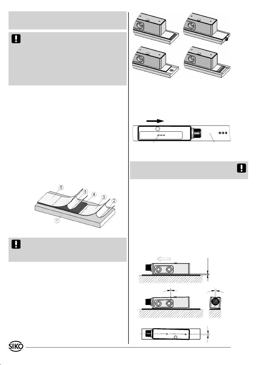
Abb. 2 Abb. 3
Abb. 4 Abb. 5
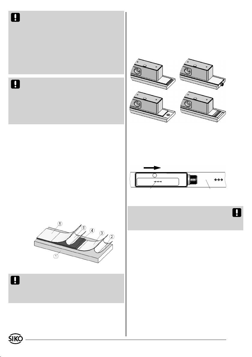
Montageschritte (Abb. 1)
Befestigungsfläche (1) sorgfältig reinigen.
•
Am Magnetband die Schutzfolie (2) des Klebe-
•
bandes (3) entfernen.
Magnetband (4) unter Berücksichtigung der
•
Abgleichrichtung aufkleben.
Magnetbandoberfläche sorgfältig reinigen.
•
Am Abdeckband (5) die Schutzfolie (6) des Kle-
•
bebandes entfernen.
Abdeckband aufkleben (an beiden Enden leicht
•
überlappen lassen).
Die überlappenden Enden des Abdeckbandes gegen
•
Ablösen sichern.
Abb. 1: Montage Magnetband
Achtung! Die Beeinflussung durch magnetische
Felder ist zu vermeiden. Insbesondere dürfen keine Magnetfelder (z.B. Haftmagnete oder andere
Dauermagnete) in direkten Kontakt mit dem Magnetband geraten.
Montagebeispiele
Die einfache Montageart, durch angeschrägtes
Schutzband (Abb. 2), ist nur in sehr geschützter
Umgebung zu empfehlen. Bei ungeschützter Um-
Montage Sensor
Der Magnetsensor muss so montiert werden, dass
die Pfeilrichtung des Sensoraufdrucks mit der
Pfeilrichtung des Bandaufdrucks übereinstimmt
(siehe Abb. 6).
Verfahrrichtung
Bedruckung auf Sensor
Bedruckung auf Band
Abb. 6: Ausrichtung
Achtung! Sobald das Abdeckband aufgebracht
wurde, ist der Bandaufdruck nicht mehr sichtbar.
Es wird empfohlen, das Abdeckband entsprechend
zu markieren.
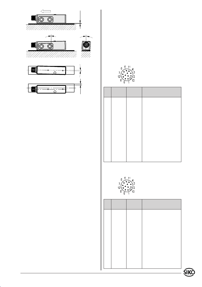
Die Lage des Sensors zum Magnetband ist genau
definiert. Bei der Montage ist insbesondere zu beachten, dass über die gesamte Messstrecke zwischen Band und Sensor ein Luftspalt eingehalten
wird, unabhängig ob das Band oder der Sensor
bewegt wird (Abb. 7). Als Montagehilfe kann die
beiliegende Abstandslehre verwendet werden.
Größere Montageabweichungen können zu Messfehlern bzw. zu Funktionsstörungen führen.
Bei Verwendung eines Abdeckbandes reduziert
sich der eff. Abstand um die Dicke des Abdeckbandes inkl. Klebefilm.
2 MSA501, MBA501 Datum 14.12.2010 Art.Nr. 85613 Änd. Stand 449/10
Page 3
Verfahrrichtung
<1°
0.2 ... 1.3
<4°
vorzusehen. Leitungsführungen parallel zu Energieleitungen vermeiden.
Schützspulen müssen mit Funkenlöschgliedern
•
beschaltet sein.
Spannungsversorgung: 4,5VDC ... 30VDC
(verpolgeschützt)
Leistungsaufnahme: <1,5W
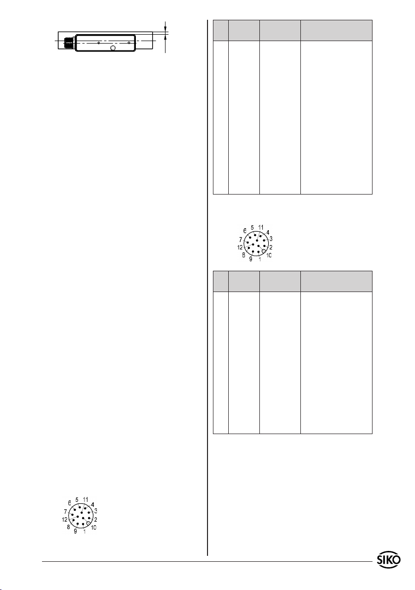
5.1 Anschlussbelegung
Anschluss SSI mit 12-pol. Stiftkontakt.
<1.5°
<3
Abb. 7: Montagetoleranzen, Maße in mm
5. Elektrischer Anschluss
Verdrahtungsarbeiten dürfen nur spannungslos
•
erfolgen.
Vor dem Einschalten sind alle Leitungsanschlüsse
•
und Steckverbindungen zu überprüfen.
Hinweise zur Störsicherheit
Alle Anschlüsse sind gegen äußere Störeinflüsse
geschützt. Der Einsatzort ist aber so zu wählen,
dass induktive oder kapazitive Störungen nicht
auf den Geber oder dessen Anschlussleitungen
einwirken können! Durch geeignete Kabelfüh-
rung und Verdrahtung können Störeinflüsse (z.B.
von Schaltnetzteilen, Motoren, getakteten Reg-
Pin Signal
mit LD
1 - - - - - 2 D+ D+
3 D- D-
4 T- T5 +UB +UB
6 /A - - 7 A - - 8 /B - - 9 B - - -
10 Config Config
11 T+ T+
12 GND GND
Anschluss RS485 (SIKONETZ3) mit 12-pol. Stiftkontakt.
Ansichtseite = Steckseite
Signal
Beschreibung
ohne LD
- - SSI-Daten + bzw. DÜA im Servi-
cemode
SSI-Daten – bzw. DÜB im Servi-
cemode
SSI-Takteingang -
Versorgungsspannung Sensor
Invertiertes Quadratursignal
Quadratursignal
Invertiertes Quadratursignal
Quadratursignal
Kalibriereingang bzw. umschal-
ten in Servicemode
SSI-Takteingang +
Masseanschluss Sensor
lern oder Schützen) vermindert werden.
Ansichtseite = Steckseite
Erforderliche Maßnahmen:
Verwendung einer geschirmten Anschlussleitung
•
mit paarweise verdrillten Litzen. Die Aderpärchen sind den entsprechenden differentiellen
Signalen zuzuordnen (D+, D-), (T+, T-), (A, /A),
(B, /B) (Empfehlung: Encoder-/Resolver-Leitung
Fa. LAPP-Kabel, 5*2*0,14²+2*0,5², Typ-Nr.:
70388728).
Die Verdrahtung von Abschirmung und Masse
•
(GND) muss sternförmig und großflächig erfolgen.
Der Anschluss der Abschirmung an den Potentialausgleich muss großflächig (niederimpedant)
erfolgen.
Das System muss in möglichst großem Abstand von
•
Leitungen eingebaut werden, die mit Störungen
belastet sind; ggfs. sind zusätzliche Maßnahmen
wie Schirmbleche oder metallisierte Gehäuse
MSA501, MBA501 Datum 14.12.2010 Art.Nr. 85613 Änd. Stand 449/10 3
Pin Signal
mit LD
1 - - - - - 2 DÜA DÜA
3 DÜB DÜB
Signal
ohne LD
Beschreibung
- - Daten +
Daten –
4 - - - - - - - - 5 +UB +UB
6 /A - - 7 A - - 8 /B - - 9 B - - -
10 Config Config
Versorgungsspannung Sensor
Invertiertes Quadratursignal
Quadratursignal
Invertiertes Quadratursignal
Quadratursignal
Kalibriereingang bzw. umschal-
ten in Servicemode
11 - - - - - - - - 12 GND GND
Masseanschluss Sensor
Page 4
6. Zubehör Anschluss-Stecker
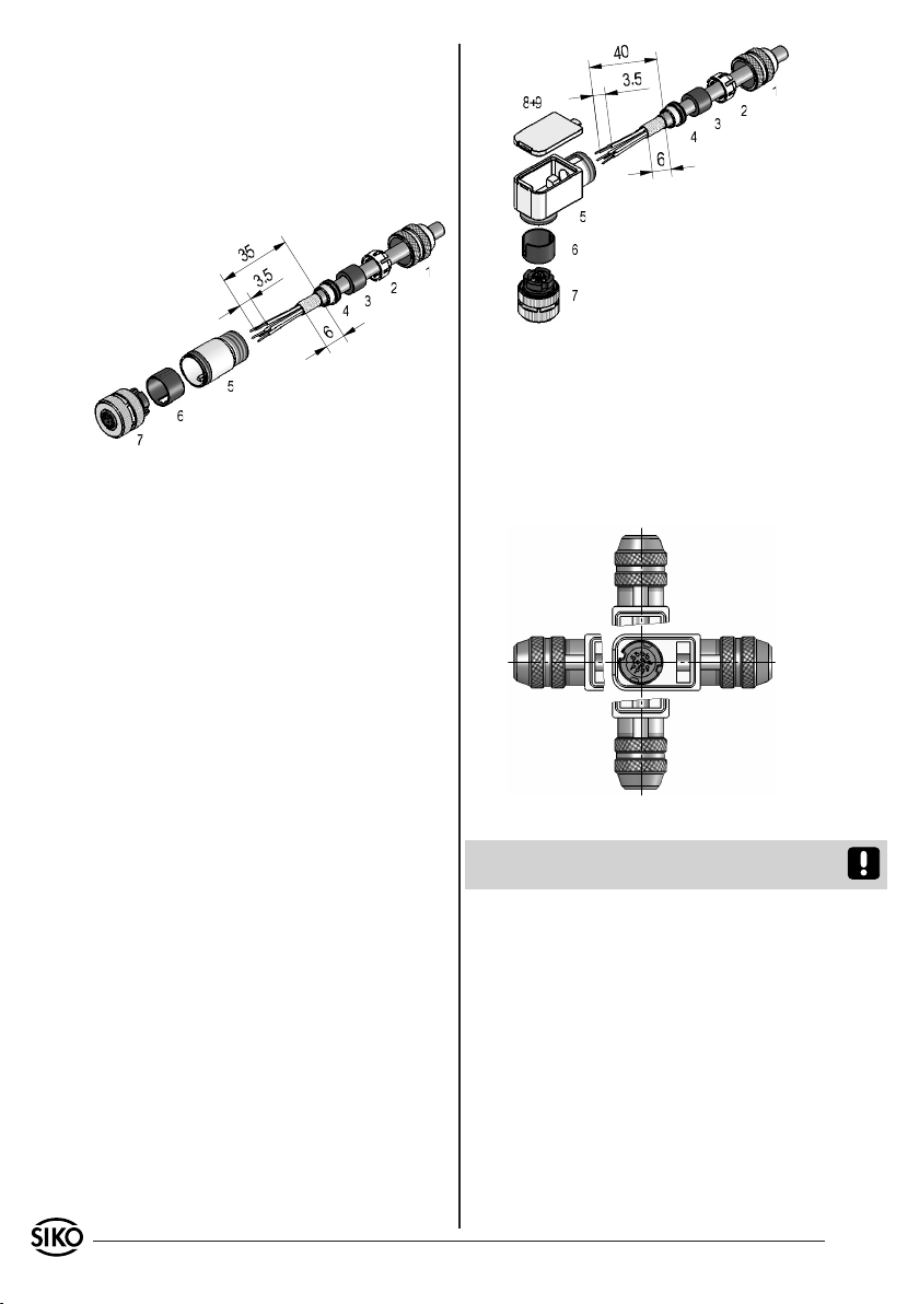
Gegenstecker gerade (12-pol.)
Bei SIKO als Zubehör unter Art.Nr. 85277 erhältlich. Litzenquerschnitt der Leitungen max.
0,25mm². Kabeldurchlass: 6-8mm.
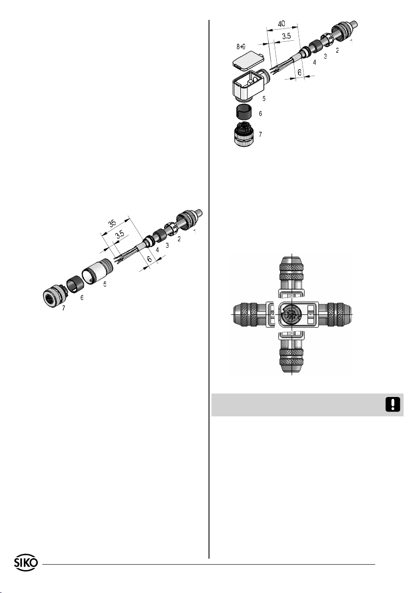
Bei der Stecker-Montage gehen Sie bitte schrittweise vor (Abb. 8):
Pos. 1 ... 4 über Kabelmantel schieben.
1.
Kabel abisolieren, Schirm kürzen und aufweiten.
2.
Schirm um Pos. 4 legen und in Pos. 5 ein-
3.
schieben.
Pos. 6 in Pos. 5 schieben.
4.
Litzen an Pos. 7 löten (entspr. Anschlussplan)
5.
und mit Pos. 5 verschrauben.
Pos. 3 in Pos. 2 stecken, beides in Pos. 1 schieben
6.
und mit Pos. 5 verschrauben.
Abb. 9: Gegenstecker gewinkelt
Ändern der Winkelstellung (von Abb. 10):
Druckschraube Pos. 1 leicht aufdrehen.
1.
Deckel Pos. 8 entfernen.
2.
Kontakteinsatz Pos. 7 aufdrehen und in ge-
3.
wünschte Winkelstellung (90° Schritte) verdrehen und wieder aufschrauben.
Deckel und Druckschraube montieren.
4.
Abb. 8: Gegenstecker gerade
Gegenstecker gewinkelt (12-pol.)
Bei SIKO als Zubehör unter Art.Nr. 85278 erhältlich. Litzenquerschnitt der Leitungen max.
0,25mm². Kabeldurchlass: 6-8mm.
Bei der Stecker-Montage gehen Sie bitte schrittweise vor (Abb. 9):
Pos. 1 ... 4 über Kabelmantel schieben.
1.
Kabel abisolieren, Schirm kürzen und aufwei-
2.
ten.
Pos. 6 in Pos. 5 schieben.
3.
Litzen durch das Gehäuse Pos. 5 führen. Schirm
4.
um Pos. 4 legen und in Pos. 5 einschieben.
Pos. 3 in Pos. 2 stecken, beides in Pos. 1 schieben
5.
und leicht auf Pos. 5 aufschrauben.
Litzen nach Anschlussplan an Kontakteinsatz
6.
Pos. 7 löten.
Kontakteinsatz Pos. 7 in Pos. 5 einschrauben.
7.
Dichtung Pos. 9 in Deckel Pos. 8 montieren.
8.
Deckel Pos. 8 einhaken.
9.
Druckschraube Pos. 1 festziehen.
10.
4 MSA501, MBA501 Datum 14.12.2010 Art.Nr. 85613 Änd. Stand 449/10
Abb. 10: Winkelstellungen
Die Softwarebeschreibung ist dem Beiblatt zu
entnehmen.
Page 5
User Information
MSA501, MBA501
Magnetic Sensor and Strip
ENGLISH
Exemplary sensor illustrations are valid for all sensor types unless described separately.
3. Summary description
The sensor collects the absolute travel information
of the encoded magnetic band MBA501. The absolute position value can be read from an upstream
control unit with a resolution of 5μm (or 10µm)
via encoder interface. In addition, an incremental
interface with quadrature signals in various resolutions is available as an option. Various sensor
operational modes (parameterization, calibration
value) can be set via external input.
In the service mode set via the "Config" external
input, the data interface (D+, D-) functions in the
bidirectional RS485 mode. Using a RS485/RS232
protocol converter, the sensor can be connected
to a PC and parameterized according to the predefined set of commands via any terminal program.
On the sensor's upper side, there is a two-colour
LED for diagnostic purposes, which permits the indication of error and other states.
MBAxxxx WT NNNNNN
batch number
carrier strip
MBA type
4. Installation
1. Warranty information
In order to carry out installation correctly, we
•
strongly recommend this document is read very
carefully. This will ensure your own safety and
the operating reliability of the device.
Your device has been quality controlled, tested
•
and is ready for use. Please observe all warnings
and information which are marked either directly
on the device or specified in this document.
Warranty can only be claimed for components
•
supplied by SIKO GmbH. If the system is used
together with other products, there is no warranty
for the complete system.
Repairs should be carried out only at our works.
•
If any information is missing or unclear, please
contact the SIKO sales staff.
For mounting, the degree of protection specified
must be observed. If necessary, protect the unit
against environmental influences such as sprayed
water, dust, knocks, extreme temperatures.
Mounting the magnetic strip
The mounting surface / measuring track must be flat.
Buckles or bumps will lead to measuring inaccuracies. Please protect the magnetic strip from mechanical damage (e.g. against blows and vibration).
For technical reasons the strip should be approx.
80mm longer than the actual measuring distance.
required tape length = measuring section + 80mm
measuring
section
(min. 200mm)
2. Identification
Magnetic sensor: Please check the particular type
of unit and type number from the identification
plate. Type number and the corresponding version
are indicated in the delivery documentation.
e.g. MSA501-0023
version number
type of unit
Magnetic strip: identification by printing on the
strip.
MSA501, MBA501 Datum 14.12.2010 Art.Nr. 85613 Änd. Stand 449/10 5
Attention! To guarantee optimal adhesion oil,
grease dust etc. must be removed by using cleansing agents which evaporate without leaving residues. Suitable cleansing agents are e.g. ketones
(acetone) or alcohols; Messrs. Loctite and 3M can
both supply such cleaning liquid. Make sure that
the surface to be glued is dry and apply the strip
Page 6
NNNNNN
with maximum pressure. Glueing should preferably
be undertaken at temperatures between 20°C to
30°C and in dry atmosphere.
Advice! When applying long pieces of magnetic
strip do not immediately remove the complete
protective foil, but rather peel back a short part
from the end sufficient to fix the strip. Now align
the strip. As the protective strip is then peeled
back and out press the tape firmly onto the mounting surface. A wall paper roller wheel could be
used to assist in applying pressure onto the magnetic strip when fixing it in position.
Mounting steps (fig. 1)
Clean mounting surface (1)
•
Remove protective foil (2) from the adhesive side
•
of the magnetic tape (3).
Stick down the magnetic strip (4) while ensuring
•
correct alignment.
Clean surface of magnetic strip carefully.
•
Remove protective foil (6) from adhesive tape on
•
the cover strip (5).
Fix cover strip (both ends should slightly over-
•
lap).
Also fix cover strip's ends to avoid unintentional
•
peeling.
Fig. 1: Mounting the magnetic strip
Attention! Do not expose the magnetic strip to
magnetic fields. Any direct contact of the magnetic
strip with magnetic fields (e.g. adhesive magnets
or other permanent magnets) is to be avoided.
Fig. 2 Fig. 3
Fig. 4 Fig. 5
Mounting the sensor
The magnetic sensor must be mounted so that the
direction of the arrow on the sensor label corresponds with the direction of the arrow on the band
label (see fig. 6).
Travel direction
Marking on sensor
Marking on strip
Fig. 6: Alignment
Caution! After attaching the cover strip, he strip
imprint is no longer visible. It is recommended
that you mark the cover strip correspondingly.
When mounting the magnetic sensor, ensure that
over the total travel distance there is a gap between sensor and strip, irrespective whether the
strip or sensor moves. In order to maintain the
correct gap when mounting the sensor, use the
distance piece supplied with it as a gauge.
Major deviations from mounting instructions may
cause measurement errors or malfunctions.
When using cover strip, the gap is reduced by
the thickness of cover strip including its adhesive film.
Travel direction
Mounting examples
0.2 ... 1.3
Mounting with chamfered ends (fig. 2) is not recommended unless the strip is installed in a safe
and protected place without environmental influ-
<1°
<4°
ences. In less protected mounting places the strip
may peel. There we recommend mounting accord.
to fig. 3 and fig. 4.
Mounting in a groove (fig. 5) best protects the
magnetic strip. The groove should be deep enough
to totally embed the magnetic strip.
6 MSA501, MBA501 Datum 14.12.2010 Art.Nr. 85613 Änd. Stand 449/10
<1.5°
Page 7
<3
Fig. 7: Mounting tolerances, dimensions in mm
5. Electrical connection
Wiring must only be carried out with power off.
•
Check all lines and connections before switching
•
on the equipment.
Interference and distortion
All connections are protected against the effects
of interference. The location should be selected
to ensure that no capacitive or inductive interferences can affect the sensor or the connection lines! Suitable wiring layout and choice
of cable can minimise the effects of interference
(e.g. interference caused by SMPS, motors, cyclic
controls and contactors).
Necessary measures:
Use of screened connection cable with trunk
•
cable in pairs. Pairs to be allocated differentialsignal wise (D+, D-), (T+, T-), (A, /A), (B, /B)
(Recommendation: encoder/-resolver line from
Messrs. LAPP-Kabel, 5*2*0,14²+2*0,5², type-no.:
70388728).
Wiring to the screen and ground (GND) must
•
be secured to a good point. Ensure that the
connection of the screen and earth is made to
a large surface area with a sound connection to
minimise impedance.
The sensor should be positioned well away from
•
cables with interference; if necessary a protective
screen or metal housing must be provided. The
running of wiring parallel to the mains supply
should be avoided.
Contactor coils must be linked with spark sup-
•
pression.
Power supply: 4,5VDC ... 30VDC
(with polarity protection)
Power consumption: <1,5W
5.1 Connection type
SSI with 12 pole coupling plug pin.
viewing side = plug-in side
Pin Signal
with LD
1 - - - - - 2 D+ D+
3 D- D-
4 T- T5 +UB +UB
6 /A - - 7 A - - 8 /B - - 9 B - - -
10 Config Config
11 T+ T+
12 GND GND
Signal
without LD
Description
- - -
SSI data + or DÜA in service
mode
SSI data - or DÜB in service
mode
SSI cycle input -
Power supply sensor
inverted quadrature signal
Quadrature signal
inverted quadrature signal
Quadrature signal
calibration input or switching over to service mode
SSI cycle input +
sensor earth connection
RS485 (SIKONETZ3) with 12 pole coupling plug
pin.
viewing side = plug-in side
Pin Signal
with LD
1 - - - - - 2 DÜA DÜA
3 DÜB DÜB
4 - - - - - 5 +UB +UB
6 /A - - 7 A - - 8 /B - - 9 B - - -
10 Config Config
11 - - - - - 12 GND GND
Signal
without LD
Description
- - -
Data +
Data -
- - -
Power supply sensor
inverted quadrature signal
Quadrature signal
inverted quadrature signal
Quadrature signal
calibration input or switching over to service mode
- - -
sensor earth connection
6. Accessory connector for connection
type
Straight mating connector (12 pole)
12 pole connector available from SIKO as accessory art. no. 85277. Wire cross section is max.
0,25mm². Cable channel: 6-8mm.
Please proceed as follows (fig. 8):
Slip parts 1 to 4 over outer cable.
1.
Strip cable, shorten and enlarge the screen.
2.
MSA501, MBA501 Datum 14.12.2010 Art.Nr. 85613 Änd. Stand 449/10 7
Page 8
Tilt the shielding around part 4 and insert in
3.
part 5.
Push part 6 into part 5.
4.
Solder stranded wires at part 7 (follow connection
5.
diagram) and screw part 5 together.
Push part 3 into part 2 and slide both parts into
6.
part 1 and screw part 5 together.
Fig. 9: Right angle mating connector
Changing the angle position (from fig. 9):
Slightly unscrew screw part 1.
1.
Remove cap part 8.
2.
Untwist part 7 and turn to the desired angle
Fig. 8: Straight mating connector
Right angle mating connector (12 pole)
3.
position (90° steps) and then twist it again.
Mount cap and screw.
4.
12 pole connector available from SIKO as accessory art. no. 85278. Wire cross section is max.
0,25mm². Cable channel: 6-8mm.
Please proceed as follows (fig. 9):
Slip parts 1 to 4 over outer cable.
1.
Strip cable, shorten and enlarge the screen.
2.
Push part 6 into part 5.
3.
Push the strands through the housing part 5.
4.
Tilt the shielding around part 4 and insert in
part 5.
Push part 3 into part 2 and slide both parts into
5.
part 1 and screw part 5 together.
Solder the strands according to the pin assign-
6.
ment table plug insert part 7.
Plug insert part 7 to be mounted into part 5.
7.
Mount the sealing part 9 into the cover part 8.
8.
Mount cover part 8.
9.
Fix pressing screw part 1.
10.
Fig. 10: Angled postions
For software description please refer to the
supplementary sheet.
SIKO GmbH
Werk / Factory:
Weihermattenweg 2
79256 Buchenbach-Unteribental
Postanschrift / Postal address:
Postfach 1106
79195 Kirchzarten
Telefon/Phone +49 7661 394-0
Telefax/Fax +49 7661 394-388
E-Mail [email protected]
Internet www.siko.de
Service [email protected]
8 MSA501, MBA501 Datum 14.12.2010 Art.Nr. 85613 Änd. Stand 449/10
 Loading...