

Page 1
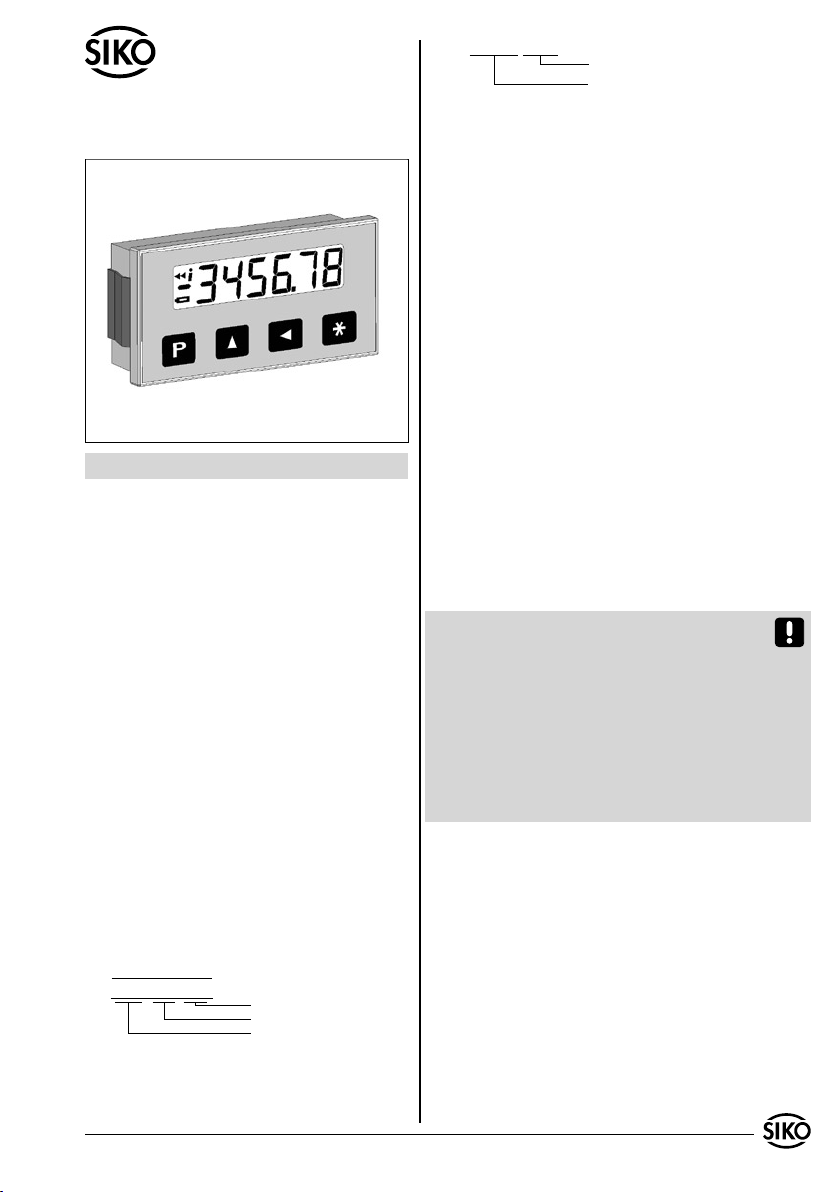
Benutzerinformation
z.B. MA564-0023
Varianten-Nr.
Geräte-Typ
MA564
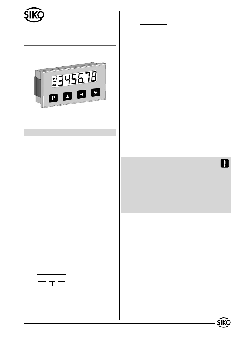
Quasiabsolute Magnetbandanzeige
3. Mechanische Montage
Die Montage darf nur gemäß der angegebenen
IP-Schutzart vorgenommen werden. Das System
muss ggfs. zusätzlich gegen schädliche Umwelteinflüsse, wie z.B. Spritzwasser, Lösungsmittel,
Staub, Schläge, Vibrationen und starke Temperaturschwankungen geschützt werden.
3.1 Einbaugehäuse EG
Für den Schalttafeleinbau gelten empfohlene Abmessungen entspr. DIN 43700.
3.4 Montage Magnetband
Die Montage muss plan zur Montagefläche bzw. der
zu messenden Strecke erfolgen. Welligkeiten verschlechtern immer die Messgenauigkeit.
DEUTSCH
1. Gewährleistungshinweise
Lesen Sie vor der Montage und der Inbetriebnahme
•
dieses Dokument sorgfältig durch. Beachten Sie zu
Ihrer eigenen Sicherheit und der Betriebssicherheit
alle Warnungen und Hinweise.
Ihr Produkt hat unser Werk in geprüftem und be-
•
triebsbereitem Zustand verlassen. Für den Betrieb
gelten die angegeben Spezifikationen und die
Angaben auf dem Typenschild als Bedingung.
Garantieansprüche gelten nur für Produkte der
•
Firma SIKO GmbH. Bei dem Einsatz in Verbindung
mit Fremdprodukten besteht für das Gesamtsystem
kein Garantieanspruch.
Reparaturen dürfen nur im Werk vorgenommen
•
werden. Für weitere Fragen steht Ihnen die Firma
SIKO GmbH gerne zur Verfügung.
Überall wo aufgrund unzureichender Befestigungsmöglichkeiten
keine geeignete Montage des Magnetbandes möglich ist, kann das
Magnetband Typ MB500 in eine als Zubehör lieferbare Profilschie-
ne (z.B. Typ PS) montiert werden.
Magnetbandeinheit.
Dadurch entsteht eine kompakte
Aus technischen Gründen muss bei der Länge, gegenüber der Messstrecke, ein Zumaß von 100mm
berücksichtigt werden.
Achtung! Um optimale Verklebungen zu erreichen müssen alle antiadhäsiven Fremdsubstanzen
(Öl, Fett, Staub usw.) durch möglichst rückstandslos verdunstende Reinigungsmittel entfernt werden. Als Reinigungsmittel eignen sich u.a. Ketone
(Aceton) oder Alkohole, die u.a. von den Firmen
Loctite und 3M als Schnellreiniger angeboten werden. Die Klebeflächen müssen trocken sein und es
ist mit höchstmöglichem Anpressdruck zu verkleben. Die Verklebungstemperatur ist optimal zwischen 20°C und 30°C in trockenen Räumen.
Tip! Bei Verklebung langer Bänder sollte die
Schutzfolie des Klebebandes über eine kurze Teil-
2. Identifikation
Magnetband: Das Magnetband ist durch eine fort-
laufende Bedruckung identifizierbar.
Beispiel Magnetbandbedruckung:
1
0
NNNN 5000
Magnetbandanzeige: Das Typenschild zeigt den
Gerätetyp mit Variantennummer. Die Lieferpapiere ordnen jeder Variantennummer eine detaillierte
Bestellbezeichnung zu.
MA564 Datum 15.01.2008 Art.Nr. 84321 Änd. Stand 004/08 1
Polbreite: 5mm
Bandgenauigkeit: 0.1mm
Seriennummer
strecke abgezogen werden, um das Band zu fixieren. Daraufhin erfolgt das Ausrichten des Bandes.
Nun kann über die restliche Länge die Schutzfolie,
unter gleichzeitigem Andruck des Bandes, seitlich
herausgezogen werden (als Hilfsmittel kann eine
Tapetenandrückwalze verwendet werden).
Montageschritte (Abb. 1)
Befestigungsfläche (1) sorgfältig reinigen.
•
Am Magnetband die Schutzfolie (2) des Klebe-
•
bandes (3) entfernen.
Magnetband (4) aufkleben.
•
Page 2
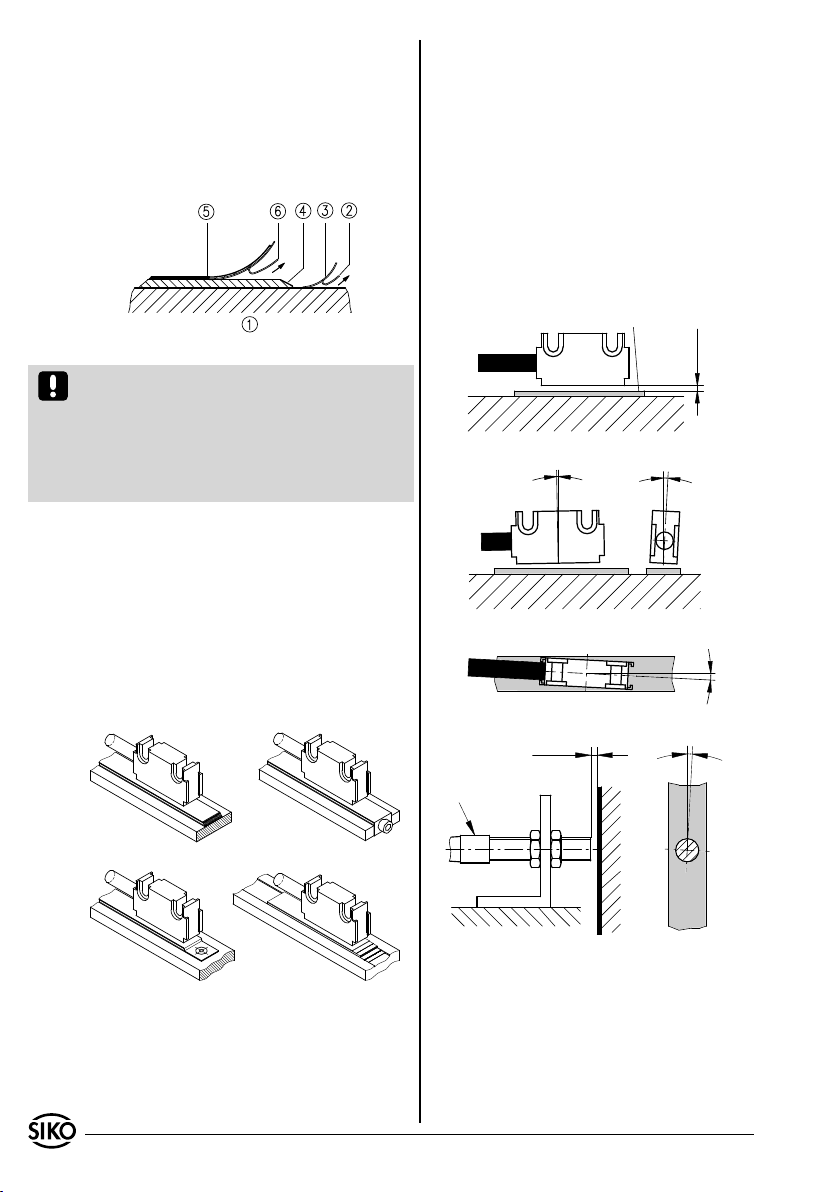
Magnetbandoberfläche sorgfältig reinigen.
•
Am Abdeckband (5) die Schutzfolie (6) des Kle-
•
bebandes entfernen.
Abdeckband aufkleben (an beiden Enden leicht
•
überlappen lassen).
Die überlappenden Enden des Abdeckbandes gegen
•
Ablösen sichern.
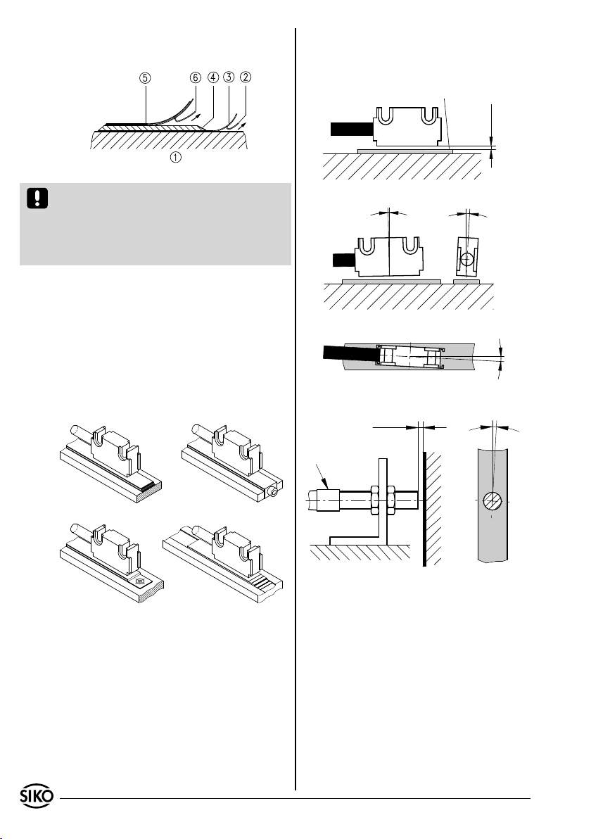
Abb. 1: Montage Magnetband
Achtung! Die Beeinflussung durch magnetische
Felder ist zu vermeiden. Insbesondere dürfen keine
Magnetfelder (z.B. Haftmagnete oder andere Dauermagnete) in direkten Kontakt mit dem Magnetband
geraten. In stromlosem Zustand werden Bewegungen oder Verstellungen des Magnetsensors von der
Folgeelektronik nicht erkannt und erfaßt.
Montagebeispiele
Die einfache Montageart, durch angeschrägtes
Schutzband (Abb. 2), ist nur in sehr geschützter
Umgebung zu empfehlen. Bei ungeschützer Umgebung besteht Abschälgefahr. In solchen Fällen
sind Montagearten, wie in Abb. 3 und 4 gezeigt,
geeigneter.
Den optimalen Schutz bietet die Montage in einer
Nut (Abb. 5), die so tief sein sollte, dass das Magnetband vollständig darin eingebettet werden kann.
Der Magnetsensor Typ F kann z.B. an einen Monta-
gewinkel mit entsprechender Befestigungsbohrung
durch Anziehen der zwei Muttern M8x0.5 befestigt
werden.
Kabel sind so zu verlegen, dass keine Beschä-
•
digungsgefahr durch Zug oder andere Maschinenteile besteht. Falls nötig Schleppkette oder
Schutzschlauch verwenden und Zugentlastung
vorsehen.
Abstandmaße zwischen Sensor und Magnetband
•
sowie Winkeltoleranzen beachten, diese müssen
über die gesamte Messstrecke eingehalten werden!
(siehe Abb. 6)
aktive Seite
0,1 ... 2mm
Abstand Sensor / Magnetband
< 1°
Maximale Fluchtungsfehler
< 3°
< 3°
0,1 ... 2mm
Pfeil
< 3°
Abb. 2 Abb. 3
Abb. 6: Ausrichtung des Sensors
Abb. 4 Abb. 5
3.3 Montage Magnetsensor
Der Magnetsensor Typ L kann durch Verwendung
von 2 Schrauben M3 über die ø3.1mm Durchgangslöcher befestigt werden.
2 MA564 Datum 15.01.2008 Art.Nr. 84321 Änd. Stand 104/08
4. Elektrischer Anschluss
Verdrahtungsarbeiten dürfen nur spannungslos
•
erfolgen!
Litzen sind mit Aderendhülsen zu versehen.
•
Vor dem Einschalten sind alle Leitungsanschlüsse
•
und Steckverbindungen zu überprüfen.
Page 3
Hinweise zur Störsicherheit
Alle Anschlüsse sind gegen äußere Störeinflüsse
geschützt. Der Einsatzort ist aber so zu wählen,
dass induktive oder kapazitive Störungen nicht
auf die Anzeige oder deren Anschlussleitungen
einwirken können! Durch geeignete Kabelfüh-
rung und Verdrahtung können Störeinflüsse (z.B.
von Schaltnetzteilen, Motoren, getakteten Reglern oder Schützen) vermindert werden.
Das System muss in möglichst großem Abstand
von Leitungen eingebaut werden, die mit Störungen belastet sind; ggfs. sind zusätzliche Maß-
nahmen wie Schirmbleche oder metallisierte
Gehäuse vorzusehen. Leitungsführungen parallel
zu Energieleitungen vermeiden.
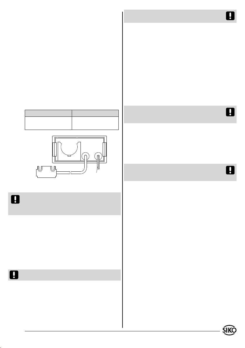
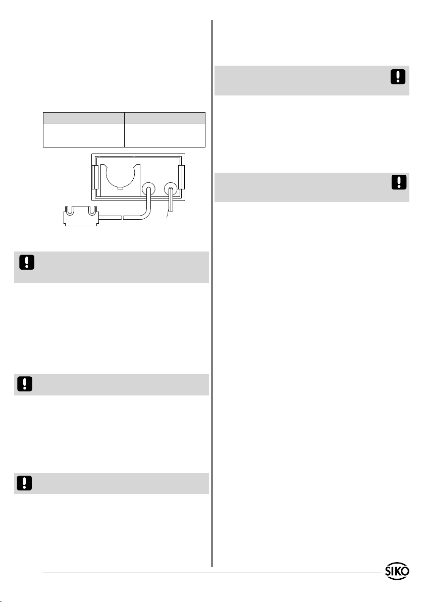
Stromversorgung: 24VDC
Belegung Litzenfarbe
+UB rot
GND schwarz
Sensor L oder F
Anschlusskabel für
Spannungsversorgung
Abb. 7: Einbaugehäuse EG
Achtung! Bei einem Batteriewechsel bleiben alle
programmierten Parameter erhalten. Der Positionswert wird nicht gespeichert und die Anzeige
muss neu referenziert werden.
Batterietypen
Batterie ist Bestandteil der Lieferung. Folgender
Standardtyp kann eingesetzt werden:
"CR2477N"
Batteriewechsel
Erscheint in der Anzeige das Batteriesymbol, so ist
baldmöglichst ein Batteriewechsel vorzunehmen.
Achten Sie beim Wechsel der Batterien unbedingt
auf die richtige Polarität!
Die Batterie kann gewechselt werden, wenn die
Versorgungsspannung eingeschaltet ist. So ist die
quasiabsolute Funktion über den Batteriewechsel
aktiv.
Batterie einlegen, ohne das die Versorgungsspannung eingeschaltet ist, so startet die Messanzeige
und geht automatisch in den Backup-Mode.
Achtung! Der Sensoranschluss darf nicht geändert
werden (z.B durch Kabelverlängerungen).
5. Inbetriebnahme
Die Bedienung und Programmierung der Anzeige
erfolgt mit den vier frontseitigen Folientasten.
Betriebsarten
Es gibt zwei Betriebsarten, in denen das Gerät
mittels der Tastatur beeinflusst werden kann:
1. Programmiermodus: Einmalige Einrichtung der
Anzeige auf die Anwendung.
2. Eingabemodus: Funktionen, die während der
normalen Anwendung benötigt werden.
Hinweis: Wird keine Batterie in die Halterung
eingelegt, funktioniert die Messanzeige wie eine
Messanzeige ohne Backup-Funktion.
6. Wartung des Magnetbandes
Die Oberfläche des Magnetbandes ist bei starker
Verschmutzung durch Staub, Späne, Feuchtigkeit,
usw., von Zeit zu Zeit mit einem weichen Lappen
zu reinigen.
Tastenfuktion / Programmiermodus / Parameterbeschreibung / Eingabemodus etc., siehe
Beiblatt Softwarebeschreibung.
MA564 Datum 15.01.2008 Art.Nr. 84321 Änd. Stand 004/08 3
Page 4
4 MA564 Datum 15.01.2008 Art.Nr. 84321 Änd. Stand 104/08
Page 5
User Information
e.g. MA564-0023
version number
type of unit
MA564
Quasi-absolute magnetic band-based
display
ENGLISH
1. Warranty information
In order to carry out installation correctly, we
•
strongly recommend this document is read very
carefully. This will ensure your own safety and
the operating reliability of the device.
Your device has been quality controlled, tested
•
and is ready for use. Please observe all warnings
and information which are marked either directly
on the device or specified in this document.
Warranty can only be claimed for components
•
supplied by SIKO GmbH. If the system is used
together with other products, there is no warranty
for the complete system.
Repairs should be carried out only at our works.
•
If any information is missing or unclear, please
contact the SIKO sales staff.
2. Identification
Magnetic strip: identification by printing on the
strip. Example Magnetic strip printing:
1
0
NNNN 5000
Electronic display: Please check the particular
type of unit and type number from the identification plate. Type number and the corresponding version are indicated in the delivery documentation.
MA564 Datum 15.01.2008 Art.Nr. 84321 Änd. Stand 004/08 5
pole pitch: 5mm
accuracy: 0.1mm
serial number
3. Installation
For mounting, the degree of protection specified
must be observed. If necessary, protect the unit
against environmental influences such as sprayed
water, dust, knocks, extreme temperatures, solvents.
3.1 Panel case type EG
For switchboard installation the recommended dimensions of DIN 43700 are valid.
3.2 Mounting the magnetic strip
The mounting surface / measuring track must be
flat. Buckles or bumps will lead to measuring inaccuracies.
For applications which do not allow properly glueing of the magnetic strip, it can be inserted into a profile rail (accessory) - eg. rail
type PS thus forming a compact mounting unit.
For technical reasons the strip should be approx.
100mm longer than the actual measuring distance.
Attention! To guarantee optimal adhesion oil,
grease dust etc. must be removed by using cleansing agents which evaporate without leaving residues. Suitable cleansing agents are eg. ketones
(acetone) or alcohols; Messrs. Loctite and 3M can
both supply such cleansing liquid. Make sure that
the surface to be glued is dry and apply the strip
with maximum pressure. Glueing should preferably be undertaken at temperatures between 20 to
30°C and in dry atmosphere.
Advice! When applying long pieces of magnetic
strip do not immediately remove the complete
protective foil, but rather peel back a short part
from the end sufficient to fix the strip. Now align
the strip. As the protective strip is then peeled
back and out press the tape firmly onto the mounting surface. A wall paper roller wheel could be
used to assist in applying pressure onto the magnetic strip when fixing it in position.
Mounting steps (see fig. 1)
Clean mounting surface (1) carefully.
•
Remove protective foil (2) from the adhesive
•
side of the magnetic strip (3).
Stick down the magnetic strip (4).
•
Clean surface of magnetic strip carefully.
•
Remove protective foil (6) from adhesive tape on
•
the cover strip (5).
Page 6
Fix cover strip (both ends should slightly overlap).
•
Also fix cover strip’s ends to avoid unintenti-
•
onal peeling.
When mounting the magnetic sensor, ensure that
•
the gap between strip and sensor and the max.
admissable deviation are maintained over the
total measuring length! (see fig. 6)
active side
0,1 ... 2mm
Fig. 1: Mounting of the magnetic strip
Attention! Do not expose the system to magnetic fields. Any direct contact of the magnetic strip
with magnetic fields (eg. adhesive magnets or
other permanent magnets) is to be avoided. Sensor movements during power loss are not captured
by the follower electronics.
Mounting examples
Mounting with chamfered ends (fig. 2) is not recommended unless the strip is installed in a safe
and protected place without environmental influences. In less protected mounting places the strip
may peel. There we recommend mounting accord.
to fig. 3 and 4.
Mounting in a groove (fig. 5) best protects the
magnetic strip. The groove should be deep enough
to totally embed the magnetic strip.
Fig. 2 Fig. 3
Gap between sensor and magnetic strip
< 1°
Max. deviation
0,1 ... 2mm
arrow
< 3°
< 3°
< 3°
Fig. 6: Mounting of sensor
Fig. 4 Fig. 5
3.3 Mounting the sensor
Use two M3 screws to fix the magnetic sensor L
via the ø3.2 mm through holes.
Magnetic sensor F can for example be mounted
by using a mounting bracket. For fixing sensor
to mounting bracket use bores and the two nuts
M8x0.5.
Cable layout should avoid damages due to cable
•
strain or other machine parts. If necessary use
a drag chain or protective hose and provide for
strain relief.
6 MA564 Datum 15.01.2008 Art.Nr. 84321 Änd. Stand 104/08
4. Electrical connection
Wiring must only be carried out with power off!
•
Provide standed wires with ferrules.
•
Check all lines and connections before switching
•
on the equipment.
Interference and distortion
All connections are protected against the effects
of interference. The location should be selected
to ensure that no capacitive or inductive interferences can affect the sensor or the connection lines! Suitable wiring layout and choice
of cable can minimise the effects of interference
Page 7
(eg. interference caused by SMPS, motors, cyclic
controls and contactors).
The sensor should be positioned well away from
cables with interference; if necessary a protec-
tive screen or metal housing must be provided.
The running of wiring parallel to the mains supply
should be avoided.
Power supply: 24VDC
Designation Color
+UB red
GND black
sensor L or F
cable for power supply
Fig. 7: Built-in housing EG
Attention! All programmed parameters will survive battery change. The position value will not be
stored and the display must be referenced anew.
Battery types
Battery is supplied with the device. The following
standard types could be used:
"CR2477N"
Change of batteries
When display shows battery symbol, battery
should be replaced as soon as possible.
When exchanging the batteries take care that
their polarity is correct!
The battery may be replaced while the supply
voltage is switched on. Thus, the quasi-absolute
function remains active beyond battery change.
When inserting the battery while the supply voltage is switched off, then the magnetic display
starts and switches over automatically to the
backup mode.
Attention! No modifiction of the sensor connection, eg. by cable extension, is permitted.
1. Programming mode: to program the display at
initial installation.
2. Input mode: to enter parameters/select func-
tions used during standard operation.
Hint: If no battery is inserted into the holder,
then the magnetic display will work like a magnetic display with no backup function.
6. Maintenance of the magnetic
strip
We recommend cleaning the magnetic strip’s surface from time to time with a soft rag. This avoids dirt (dust, chips, humidity ...) sticking to the
strip.
Key's function / Programming mode / Parameter description / Input mode etc., see enclosed
page with software description.
5. Commissioning
Four membrane keys on the front panel are used
for programming and operation of the display.
Operating modes
There are two operating modes accessible via the
keyboard:
MA564 Datum 15.01.2008 Art.Nr. 84321 Änd. Stand 004/08 7
Page 8
SIKO GmbH
Werk / Factory:
Weihermattenweg 2
79256 Buchenbach-Unteribental
Postanschrift / Postal address:
Postfach 1106
79195 Kirchzarten
Telefon/Phone +49 7661 394-0
Telefax/Fax +49 7661 394-388
E-Mail [email protected]
Internet www.siko.de
Service [email protected]
8 MA564 Datum 15.01.2008 Art.Nr. 84321 Änd. Stand 104/08
 Loading...