

Page 1
3
5
Benutzerinformation
MA508
Magnetband Messanzeige
DEUTSCH
1. Gewährleistungshinweise
Lesen Sie vor der Montage und der Inbetriebnahme
•
dieses Dokument sorgfältig durch. Beachten Sie zu
Ihrer eigenen Sicherheit und der Betriebssicherheit
alle Warnungen und Hinweise.
Ihr Produkt hat unser Werk in geprüftem und be-
•
triebsbereitem Zustand verlassen. Für den Betrieb
gelten die angegeben Spezifikationen und die
Angaben auf dem Typenschild als Bedingung.
Garantieansprüche gelten nur für Produkte der
•
Firma SIKO GmbH. Bei dem Einsatz in Verbindung
mit Fremdprodukten besteht für das Gesamtsystem
kein Garantieanspruch.
Reparaturen dürfen nur im Werk vorgenommen
•
werden. Für weitere Fragen steht Ihnen die Firma
SIKO GmbH gerne zur Verfügung.
möglich. Als Maßstab dienen Magnetbänder bzw.
Magnetringe mit einer Pollänge von 5mm. Der
Positionswert wird mittels 5-stelligem LC-Display
angezeigt.
4. Mechanische Montage
Die Montage darf nur gemäß der angegebenen IPSchutzart vorgenommen werden. Das System muss
ggf. zusätzlich gegen schädliche Umwelteinflüsse,
wie z.B. Spritzwasser, Staub, Schläge, Temperatur
geschützt werden.
Achtung! Die Beeinflussung durch magnetische
Felder ist zu vermeiden. Insbesondere dürfen keine Magnetfelder (Haft- oder Dauermagnete) in direkten Kontakt mit dem Magnetband geraten.
Folgende Punkte führen unverzüglich zum Verfall
der Garantie:
Zerlegen der Messanzeige (soweit dies nicht
•
ausdrücklich in dieser Benutzerinformation beschrieben wird).
Schläge auf das Gehäuse oder die Folientastatur,
•
da dadurch interne Elemente beschädigt werden
können.
Unsachgemäße Befestigung der Messanzeige.
•
Lagerung und Betrieb der Messanzeige außerhalb
•
der spezifizierten Umgebungsbedingungen.
4.1 Anbau der Messanzeige
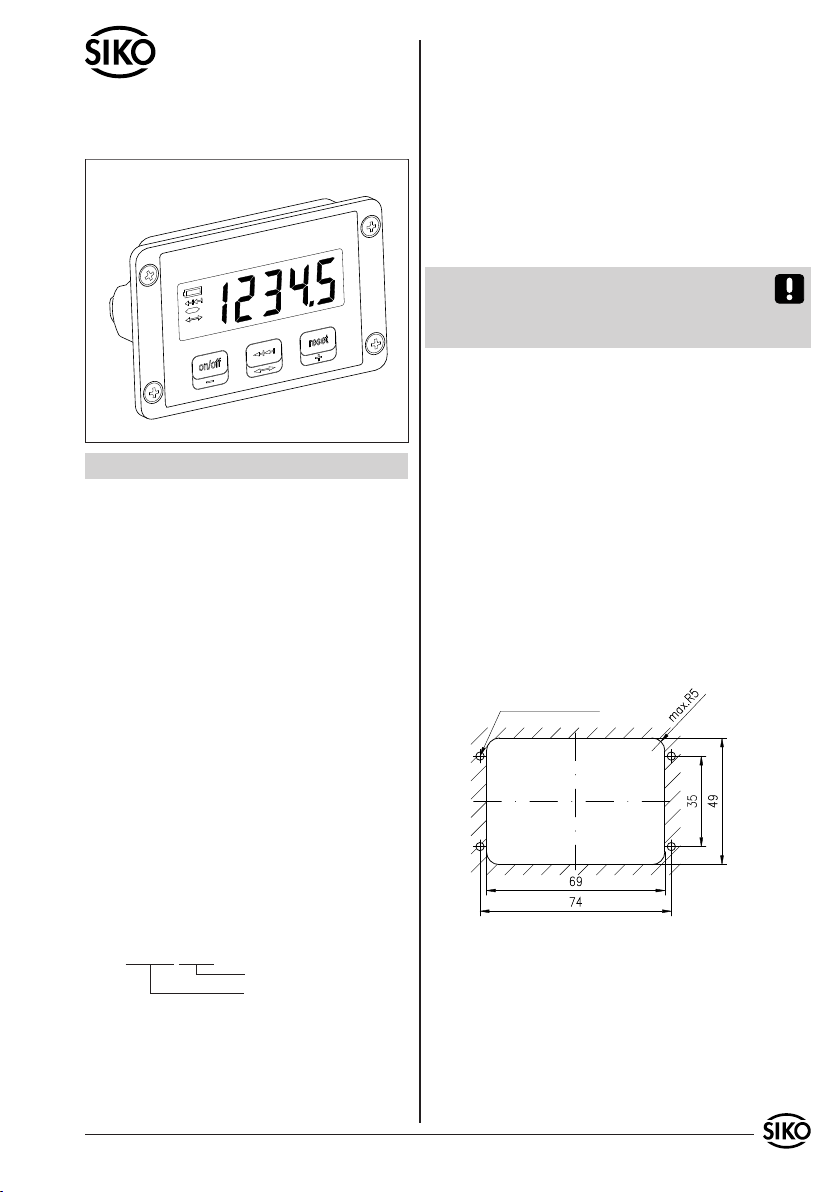
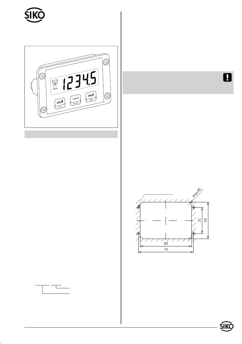
Das Gehäuse kann mittels 4 Montagebohrungen in
•
einem Schalttafelausschnitt befestigt werden.
für Gewinde M3
2. Identifikation
Das Typenschild zeigt den Gerätetyp mit Variantennummer. Die Lieferpapiere ordnen jeder Variantennummer eine detaillierte Bestellbezeichnung zu.
z.B. MA508-0023
Varianten-Nr.
Geräte-Typ
3. Kurzbeschreibung
Die Messanzeige MA508 ist ein netzunabhängiges
Messsystem. Die integrierte Batterie garantiert
eine mehrjährige Betriebsdauer. Hierdurch wird
eine quasi absolute Weg- bzw. Winkelmessung
MA508 Datum 11.03.2008 Art.Nr. 83093 Änd. Stand 77/08 1
Abb. 1: Schalttafelausschnitt
4.2 Montage Magnetsensor:
Die Abstandsmaße zwischen aktiver Sensorfläche
•
und Magnetband, sowie die Winkeltoleranzen sind
zu beachten. Diese müssen über die gesamte
Messstrecke eingehalten werden.
Innerhalb der angegebenen Lageabweichungen
•
ist der Messfehler vernachlässigbar.
Die Addition der Montagetoleranzen in allen
•
Page 2
Ebenen muss vermieden werden.
Bei externem Sensor ist die Anschlussleitung so zu
•
verlegen, dass keine Gefahr der Beschädigung durch
andere Maschinenteile oder Zugkraft besteht.
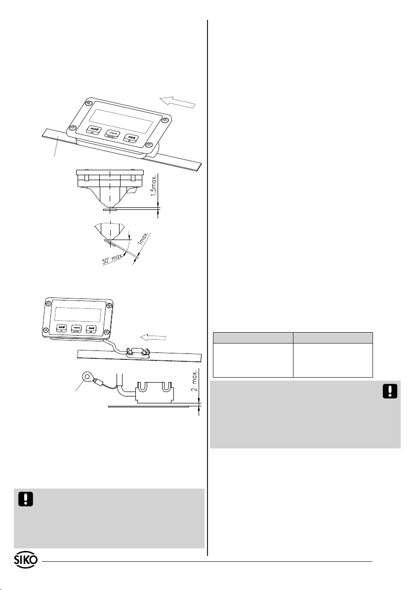
4.2.1 Sensorausführung integrierter Sensor (IS):
Verfahrrichtung:
positive Zählrichtung
Magnetband
Abb. 2: Montagetoleranzen interner Sensor
4.2.2 Sensorausführung externer Sensor (ES):
Verfahrrichtung:
positive Zählrichtung
PE-Anschluss
(Kabelschuh für M3 nur bei
Sensorkabellänge >0,3m)
Abb. 3: Montagetoleranzen externer Sensor
5. Elektrischer Anschluss
Ein kundenseitiger elektrischer Anschluss entfällt,
da das Gerät netzunabhängig über eine integrierte
Lithium Batterie versorgt wird und der Sensor fest
mit der Anzeige verbunden ist.
Achtung! Die Anschlussleitung des Magnetsensors
darf nicht aufgetrennt bzw. verlängert werden! Da
jede Anzeige explizit auf den angeschlossenen Sensor abgeglichen ist, kann ein Austausch (z.B. nach
Kabelbruch oder mechanischer Zerstörung des Sensors) nur werksmäßig vorgenommen werden.
Hinweise zur Störsicherheit
Der Einsatzort der Messanzeige, sowie bei ex-
ternem Sensors des Magnetsensors, ist so zu
wählen, dass induktive oder kapazitive Störungen nicht auf das Gerät oder dessen Anschlussleitungen einwirken können! Durch geeignete
Kabelführung und Verdrahtung können Störeinflüsse (z.B. von Schaltnetzteilen, Motoren, getakteten
Reglern oder Schützen) vermindert werden.
Erforderliche Maßnahmen:
Das System muss in möglichst großem Abstand von
•
Leitungen eingebaut werden, die mit Störungen
belastet sind; ggfs. sind zusätzliche Maßnahmen
wie Schirmbleche oder metallisierte Gehäuse
vorzusehen. Leitungsführungen parallel zu Energieleitungen vermeiden.
Schützspulen müssen mit Funkenlöschgliedern
•
beschaltet sein.
Bei Sensorkabellänge > 0,3m, muss das Anzeigen-
•
gehäuse und der PE-Anschluss beim Sensor (siehe
Abb. 3) ordnungsgemäß geerdet werden!
Spannungsversorgung
Die automatische Überwachung des Ladezustandes
gewährleistet einen sicheren Zählbetrieb auch bei
ausgeschaltetem LC-Display über mehrere Jahre.
Die Nutzungsdauer hängt im Wesentlichen von der
gewählten Einschaltdauer des LC-Displays ab. Es
können folgende Richtwerte (bei 23°C) genannt
werden:
Einschaltdauer Batterielebensdauer
100% ca. 6 Jahre
40% ca. 9 Jahre
20% > 10 Jahre
Achtung! Sobald die Batteriespannung einen definierten Schwellenwert unterschreitet, wird dies
in der Anzeige durch ein Symbol signalisiert. In
diesem Stadium ist die Funktion der Messanzeige
über einen begrenzten Zeitraum gewährleistet, jedoch sollte baldmöglichst ein Austausch der Batterie bei SIKO vorgenommen werden.
6. Bedienung und Betriebsarten
Die Bedienung der Anzeige bzw. der Wechsel in unterschiedliche Betriebsarten erfolgt mit den drei
frontseitigen Folientasten. Die Tasten können je
nach Betriebsart weitere Funktionen besitzen. Sie
werden einzeln und zeitabhängig betätigt.
2 MA508 Datum 11.03.2008 Art.Nr. 83093 Änd. Stand 77/08
Page 3
Programmierung des Offset Wertes:
Änderung des Wertes durch die Tasten (+)
1
2
3
und (-). Bei kurzem Druck wird der Wert nur
um ein Inkrement geändert, bei längerem Druck
(Schnelllauf) werden Stellen im Schnelllauf inkrementiert bzw. dekrementiert.
Übernehmen des programmierten Offset Wertes:
Erneuter Druck auf die Taste . Die Änderung
wird übernommen und die Betriebsart wechselt
54
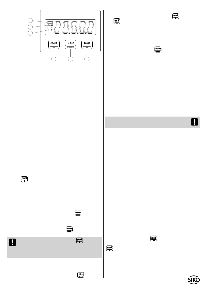
Anzeige Low-Batt
1.
Anzeige Kettenmaß aktiv
2.
Anzeige Offsetwerteingabe
3.
-LC-Display Ein-/Ausschalten
4.
-Offsetwert dekrementieren
-Kettenmaß
5.
-Offseteingabe
-Reset / Kalibrierung
6.
-Offsetwert inkrementieren
6.1 Absolutmaß
Nach der Inbetriebnahme befindet sich die Messanzeige in der Betriebsart "Absolutmaß". Hier wird
der verrechnete Positionswert angezeigt (siehe
Berechnung des Anzeigewertes).
Es ist notwendig, das Messsystem in den folgenden Fällen zu kalibrieren:
Nach der ersten Inbetriebnahme
•
Nach einem Austausch der Backup Batterie
•
Falls der Sensor in eine Lage außerhalb der
•
Montagetoleranzen gebracht wurde.
Die Kalibrierung erfolgt durch Druck auf die Taste
. Damit wird der Positionswert auf den Wert
des Offsets (Default = 0) gesetzt. In Abhängigkeit
des Parameters "Reset Delay" reagiert die Taste
auf kurzen Druck oder verzögert.
6
wieder in das "Absolutmaß". Nachdem Anzeigenparameter programmiert wurden (siehe Kapitel
7. Programmierung der Benutzerparameter) bzw.
nach einem "PowerOn" (Batteriewechsel) beträgt
der Offset Wert = 0.
6.4 ERROR
In den Zustand "ERROR" wird die MA508 unabhängig davon versetzt, ob das Display ein- oder ausgeschaltet ist. Bei eingeschaltetem Display wird
der Status "ERROR" durch gleichnamigen Text auf
dem Display signalisiert.
Achtung! Sobald der Status "ERROR" eintritt, werden Positionsänderungen nicht mehr erfasst.
Mögliche Ursachen für den ERROR Status:
Der Abstand zwischen Magnetband und der Sensor-
1.
abtastfläche liegt außerhalb der Montagetoleranz.
-> Ausrichtung und Montagetoleranzen Magnetsensor/ Band überprüfen und ggf. neu justieren.
Überschreitet der Absolutzähler den Wert
2.
+99´999 bzw. wird der Wert -99´999 unterschritten, wird bei eingeschaltetem Display der Wert
"FULL" angezeigt. Intern werden Positionsänderungen weitergezählt. Sobald der interne
Zähler jedoch den Wert ±180´000 übersteigt,
wechselt die Anzeige in die Betriebsart "ERROR".
-> Bei Überschreiten des Wertebereiches ist der
Parameter Interpolationsschritte/Pol zu reduzie-
6.2 Kettenmaß
Wechsel in die Betriebsart "Kettenmaß":
Durch kurzen Druck auf die Taste . Im Display
erscheint nun der Wert "0".
Rückkehr in die Betriebsart "Absolutmaß":
Erneutes Drücken der Taste . Änderungen des
Positionswertes werden übernommen.
Achtung! Ein Druck auf die Taste in der Be-
triebsart "Kettenmaß" bewirkt ebenfalls den Wechsel in das "Absolutmaß", jedoch wird die Anzeige
gleichzeitig neu kalibriert.
6.3 Offseteingabe
Eintritt in die Betriebsart "Offset Eingabe":
Durch längeren Druck auf die Taste .
MA508 Datum 11.03.2008 Art.Nr. 83093 Änd. Stand 77/08 3
ren (siehe Parameterbeschreibung: Auflösung
bzw. Interpolationsschritte/Pol).
Die maximal mögliche Verfahrgeschwindigkeit
3.
des Sensors wurde überschritten.
-> Geschwindigkeit reduzieren
Aufhebung des Status "ERROR":
Display einschalten (Taste ), den Sensor auf
den Kalibrierpunkt positionieren und die Taste
betätigen.
Mit dem Parameter "Reset Delay" kann bestimmt
werden, ob die Taste auf kurze Betätigung oder
erst nach ca. 2 sec. reagiert (Berührungsschutz).
Sofern nicht der LC-Display Mode "LCD ist immer
eingeschaltet" ("Lc.On") programmiert wurde, wirkt
Page 4
sich der "ERROR" Status direkt auf das Display Verhalten (siehe Kapitel 8. Parameterbeschreibung) aus:
Einschalten ist nur per Taste möglich.
•
Sensorbewegungen werden nicht mehr ausge-
•
wertet.
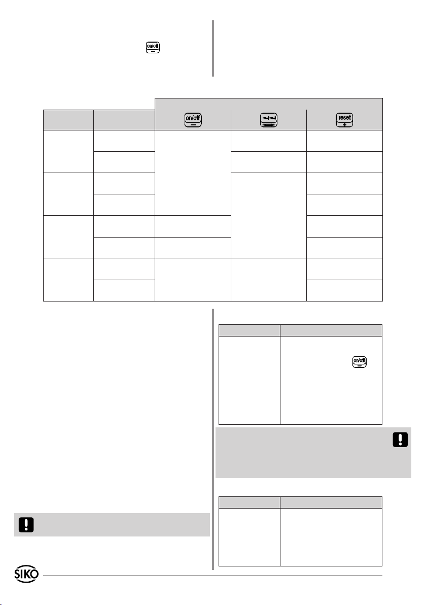
Zusammenfassung der Betriebsarten und Tastenfunktionen
Betriebsart Betätigungszeit
<1 sec.
Absolutmaß
Kettenmaß
Offset
Eingabe
ERROR
Zustand
> 2 sec.
< 1 sec.
> 2 sec. Kalibrieren
< 1 sec.
> 2 sec.
< 1 sec.
> 2 sec. Kalibrieren
LCD ein-/
ausschalten
(in Abhängigkeit
von Parameter
LC-Display Mode)
Offsetwert
dekrementieren
Offsetwert
"-" Schnelllauf
LCD ein-/
ausschalten
(in Abh. v. Parameter
LC-Display Mode
Umschalten in die
Offsetwerteingabe
Taste
Umschalten ins
Kettenmaß
Umschalten ins
Absolutmaß
keine Funktion
Kalibrieren, falls
Reset Delay OFF
Kalibrieren
Kalibrieren, falls
Reset Delay OFF
Offsetwert
inkrementieren
Offsetwert
"+" Schnelllauf
Kalibrieren, falls
Reset Delay OFF
7. Programmierung der Benutzerpa-
rameter
Die Programmierung der Messanzeige erfolgt mittels eines Handgerätes, das unter der Bezeichnung
"PTM" als Zubehörartikel bei SIKO erhältlich ist. Zur
Programmierung muss der Programmierstecker durch
die Öffnung auf der Rückseite der MA508 in die Anschlüsse eingesteckt werden. Um den elektrischen
Kontakt zu gewährleisten, sollte der Stecker leicht
verkantet werden. Nachdem die Parameter im "PTM"
wunschgemäß konfiguriert wurden (siehe Benutzerinformation "PTM"), können sie in die Messanzeige
übertragen werden. Nach erfolgreicher Übertragung
steht der Positionswert der MA508 auf "0" und das
Gerät befindet sich in der Betriebsart "Absolutmaß".
Nach der Programmierung ist der Offsetwert = 0, sowie der Kalibrierpunkt gelöscht.
Die Messanzeige wird mit einer Standardprogrammierung ab Werk ausgeliefert.
Achtung! Diese Werte sind nicht identisch mit
den "PowerOn" Defaultwerten.
4 MA508 Datum 11.03.2008 Art.Nr. 83093 Änd. Stand 77/08
Zusammenfassung der Werkseinstellung:
Parameter Wert
LC-Display Mode Display schaltet ab und wird
durch Sensorbewegung oder
Druck auf die Taste ge-
weckt.
Auflösung 0.1 mm
Dezimalpunkt 0.0
Zählrichtung Positiv
Reset Delay Aus
Achtung! Bei ausgeschaltetem LC-Display bleiben
die programmierten Parameter bestehen. Falls jedoch die Spannungsversorgung zur Batterie unterbrochen wird, werden sämtliche Parameter wieder
auf die "PowerOn" Defaults gesetzt.
Zusammenfassung der "PowerOn" Defaultwerte:
Parameter Wert
LC-Display Mode Display immer eingeschaltet
Auflösung 0.1 mm
Dezimalpunkt 0.0
Zählrichtung Positiv
Reset Delay Aus
Page 5
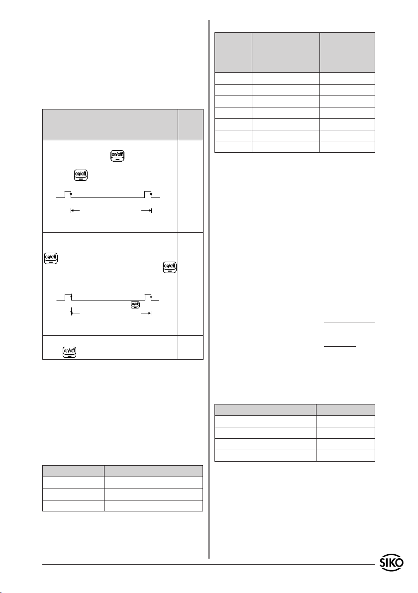
8. Parameterbeschreibung
Nachfolgend werden alle Messanzeigenparameter
und deren Funktion erläutert. In der Spalte "Menütext PTM" ist die zugeordnete Textanzeige des
PTMs dargestellt. Im PTM wird hierzu die Betriebsart "PCon" ausgewählt (siehe Benutzerinformation
"PTM").
8.1 LC-Display Mode
Beschreibung Menü-
Der Anwender weckt das LC-Display durch
Betätigen der Taste . Das LC-Display
wird automatisch beim nächsten Betätigen
der Taste oder nach 15 Minuten Inaktivität ausgeschaltet.
LCD
Ein
LC-Display LC-Display eingeschaltet
Aus
Ausschalten
nach 15 min.
Das LC-Display erscheint bei Sensor-Bewegung* oder durch Betätigen der Taste
. Das LC-Display wird automatisch
beim nächsten Betätigen der Taste
oder nach 15 Minuten Inaktivität ausgeschaltet.
LCD
Ein mit Bewegung oder Taste
LC-Display LC-Display eingeschaltet
Ausschalten
nach 15 min.
LC-Display ist immer eingeschaltet. Die
Taste hat keinen Einfluss.
* Die Bedingung Sensor-Bewegung ist erfüllt, sobald
der Sensor um mindestens 2,5mm bewegt wurde
und kein "ERROR"-Status vorliegt (siehe Kapitel
7.4 ERROR). Inaktivität liegt entsprechend dann
vor, wenn der Sensor innerhalb von ca. 15min.
nicht um ebenfalls mindestens 2,5mm bewegt
wird. Das LC-Display wird dann ausgeschaltet.
8.2 Auflösung
8.2.1 Lineare Messung:
Auflösung Menütext PTM
0,1mm IP.50
1mm IP. 5
10mm IP.0.5
text
PTM
"Lc.tA"
Oder
"Lc.SE"
Aus
Oder
"Lc.On"
8.2.2 Rotative Messung:
Auflösung Beschreibung
(Angezeigter Wert
im Display nach
100mm)
Menütext PTM
Interpolati-
onsschritte
pro Pol
0,1mm 1000 IP.50
10mm* 10 IP.0.5
5mm* 20 IP. 1
2,5mm* 40 IP. 2
2mm* 50 IP.2.5
1,25mm* 80 IP. 4
1mm* 100 IP. 5
* Diese Stufen sind für rotative Anwendungen
vorgesehen, um den Faktor Spindelsteigung in der
Messanzeige zu berücksichtigen.
Berechnung des Anzeigewertes
Anzeigewert = Anzahl
x Interpolations-
Pole
schritte pro Pol
Beispiel:
Spindelsteigung: 4mm / Umdrehung
Maßstab: Magnetring mit Polzahl 20
Nach 10 Umdrehungen (d.h. 40mm in Verfahrrichtung) soll im Display der Wert 40.0 angezeigt
werden. Das Messsystem erfasst über diese Strecke
10 x 20 Pole (= 200 Pole).
Interpolationsschritte pro Pol =
Anzeigewert
Anzahl Pole
=
400
200
= 2
Dies entspricht einer Auflösung von 2,5mm.
8.3 Position des Dezimalpunktes
Beschreibung Menütext PTM
Kein Dezimalpunkt "dP. 0"
1 Nachkommastelle: "0.0" "dP. 1"
2 Nachkkommastellen: "0.00" "dP. 2"
3 Nachkommastellen: "0.000" "dP. 3"
Die Position des Dezimalpunktes wird nur für die
Darstellung im Display verwendet und geht nicht
in die Berechnung ein.
MA508 Datum 11.03.2008 Art.Nr. 83093 Änd. Stand 77/08 5
Page 6
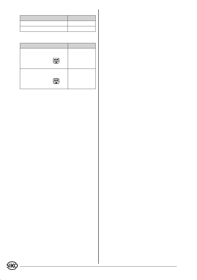
8.4 Zählrichtung (siehe mechanische Montage)
Beschreibung Menütext PTM
Die Zählweise ist positiv "Zr.uP"
Die Zählweise ist negativ "Zr.dn"
8.5 Reset Delay
Beschreibung Menütext PTM
Die Reset Funktion der MA508
wird nach kurzer Betätigung
(< 1 sec.) der Taste ausgelöst.
Die Reset Funktion der MA508
wird nach langer Betätigung
(> 2 sec.) der Taste ausgelöst.
"rd.no"
"rd.On"
9. Fehlerbehandlung
Fehlerbeschreibung:
Anzeige "ERROR" lässt sich nicht löschen.
•
Mögliche Ursachen / Abhilfe:
Abstand bzw. Winkel zwischen aktiver Sensor-
•
fläche und Magnetband liegt außerhalb der
Montagetoleranzen.
Fehlerbeschreibung:
Anzeigewert stimmt nicht mit der Position überein
•
nachdem das System kalibriert und der Sensor
verfahren wurde.
Mögliche Ursachen / Abhilfe:
Parameter Auflösung kontrollieren und überprüfen
•
ob für die Applikation verwendbar.
Abstand bzw. Winkel zwischen Sensorfläche und
•
Magnetband optimieren.
Fehlerbeschreibung:
Nach dem Einschalten des LC-Displays erscheint
•
das Batteriesymbol.
Mögliche Ursachen / Abhilfe:
Gerät zum Austausch der Batterie zu SIKO
•
schicken.
6 MA508 Datum 11.03.2008 Art.Nr. 83093 Änd. Stand 77/08
Page 7
3
5
User Information
MA508
Magnetic strip Electronic display
ENGLISH
1. Warranty information
In order to carry out installation correctly, we
•
strongly recommend this document is read very
carefully. This will ensure your own safety and
the operating reliability of the device.
Your device has been quality controlled, tested
•
and is ready for use. Please observe all warnings
and information which are marked either directly
on the device or specified in this document.
Warranty can only be claimed for components
•
supplied by SIKO GmbH. If the system is used
together with other products, there is no warranty
for the complete system.
Repairs should be carried out only at our works.
•
If any information is missing or unclear, please
contact the SIKO sales staff.
quasi-absolute distance or angle measurement.
Magnetic strips or rings, respectively, having a
pole length of 5 mm serve as the scale. The position value is displayed via a 5-digit LC display.
4. Installation
For mounting, the degree of protection specified
must be observed. If necessary, protect the unit
against environmental influences such as sprayed
water, dust, knocks, extreme temperatures.
Attention! Avoid influences by magnetic fields.
Take special care that no magnetic fields (holding
or permanent magnets) come into direct contact
with the magnetic strip.
The following points will result in immediate
forfeit of guarantee
Disassembly of the electronic display (unless
•
explicitly described in the present User information).
Knocks on the housing or membrane keyboard since
•
internal components could be damaged.
Improper fastening of the electronic display.
•
Storage and operation of the electronic display
•
outside the specified ambient conditions.
4.1 Mounting the electronic display
The housing can be fastened by means of 4
•
mounting bores in a front panel cutout.
for screw M3
2. Identification
Please check the particular type of unit and type
number from the identification plate. Type number
and the corresponding version are indicated in the
delivery documentation.
e.g. MA508-0023
version number
type of unit
3. Short description
The electronic display MA508 is a mains-independent measuring system. The integrated battery
ensures several years of service life thus enabling
MA508 Datum 11.03.2008 Art.Nr. 83093 Änd. Stand 77/08 7
Fig. 1: Panel cutout
4.2 Mounting the magnetic sensor
The distance measures between active sensor
•
surface and magnetic strip as well as the angle
tolerances must be observed and kept over the
whole measurement section.
The measuring error is negligible within the
•
specified positional deviations.
Addition of the mounting tolerances on all levels
•
should be avoided.
In case of an external sensor the service line
•
Page 8
should be layed so as to exclude any danger of
damage caused by other machine parts or tensile
strength.
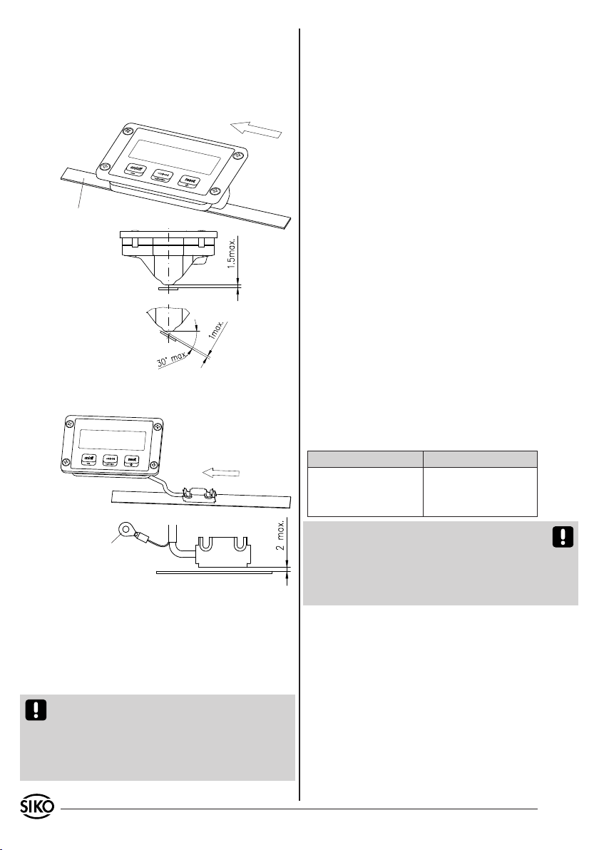
4.2.1 Sensor design: integrated sensor (IS):
travel direction:
positive counting direction
magnetic strip
Fig. 2: Mounting tolerances of internal sensor
4.2.2 Sensor design: external sensor (ES):
travel direction:
positive counting direction
PE-connection
(cable shoe for M3 only with
sensor cable length > 0,3 m)
Fig. 3: Mounting tolerances of external sensor
Interference and distortion
All connections are protected against the effects
of interference. The location should be selected
to ensure that no capacitive or inductive interferences can affect the encoder or the connection lines! Suitable wiring layout and choice
of cable can minimise the effects of interference
(eg. interference caused by SMPS, motors, cyclic
controls and contactors).
Necessary measures:
The unit should be positioned well away from
•
cables with interference; if necessary a protective
screen or metal housing must be provided. The
running of wiring parallel to the mains supply
should be avoided.
Contactor coils must be linked with spark sup-
•
pression.
With sensor cable lengths > 0,3m the display's
•
housing and the PE-connection near the sensor
(see fig. 3) must be properly earthed!
Power supply
The automatic monitoring of the storage status
ensures safe counting operation for many years
even when the LC display is turned off. The service
life depends essentially on the chosen duty cycle
of the LC display. The following standard values
apply (at 23°C):
Duty cycle Battery life
100% ca. 6 years
40% ca. 9 years
20% > 10 years
Attention! As soon as the battery voltage falls
below a defined value, this will be signalled by
a symbol on the display. On this stage, the functioning of the electronic display is ensured for a
limited time. However, the battery should be replaced by SIKO as soon as possible.
5. Electrical connection
The customer needn't provide a service line since
the device is operated mains-independent via an
integrated lithium battery and the sensor is hardwired to the display.
Attention! The service line of the magnetic sensor
must not be ripped open or extended since ebery
6. Operation and operational modes
The operation of the display or the change to
other operating modes is perfored by means of the
three membrane keys on the front side. Depending
on the operating mode the keys may have additional functions. They are actuated individually and
time-dependent.
display has beed configured explicitly to the connected sensor. Therefore, it can be replaced in our
factory only (e.g., because a cable break or mechanical destruction of the sensor has occured).
8 MA508 Datum 11.03.2008 Art.Nr. 83093 Änd. Stand 77/08
Page 9
6.3 Input offset value
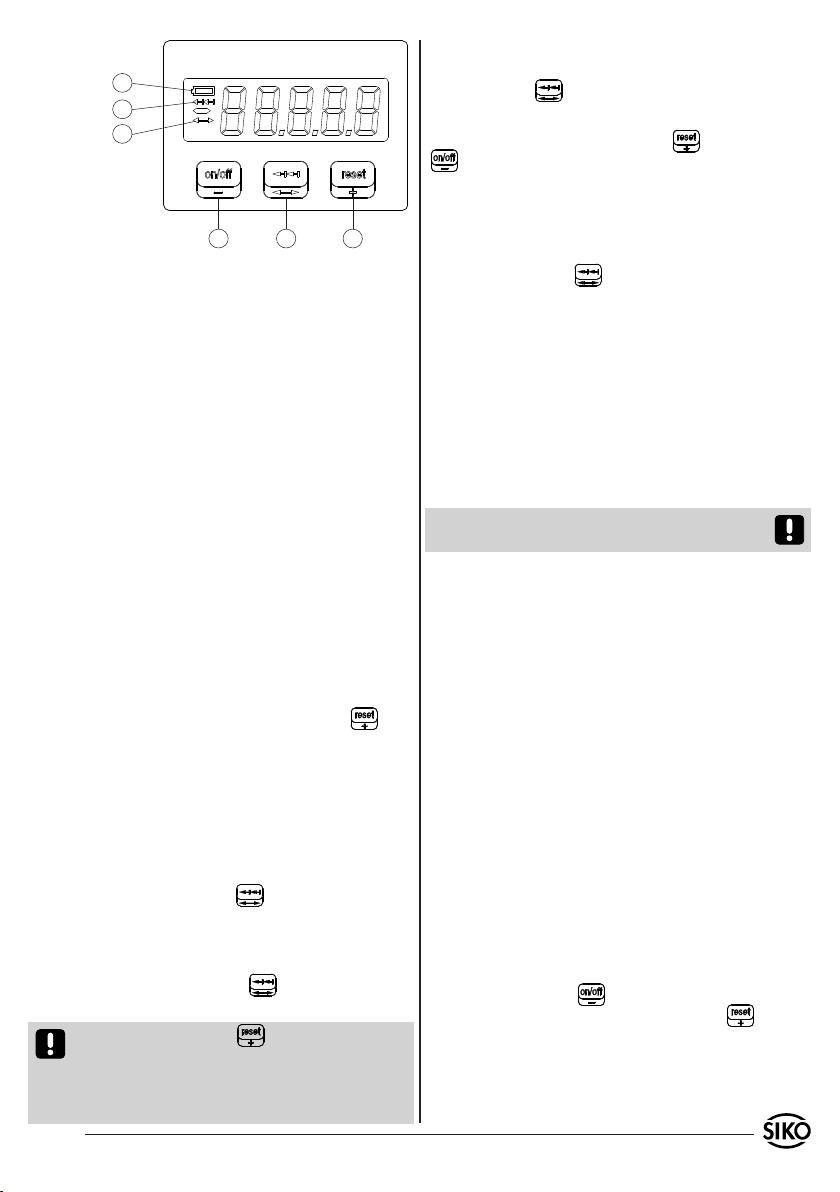
1
2
3
Entering the operation mode "Offset input":
By pressing the key for a longer time.
Programming the offset value:
Change of the value by pressing the (+) and
(-) keys. By pressing the keys shortly, the
value will be changed by one increment only, if
pressed for a longer time (fast mode) the digits
are incremented or decremented in the fast mode.
54
Display: Low-Batt
1.
Display: incremental measurement active
2.
Display: input of offset value
3.
-Turn on/off LC-Display
4.
-Decrement offset value
-Incremental measure
5.
6
Taking over the programmed offset value:
Renewed pressing the key. The changed value
is taken over and the operating mode changes to
"absolute measurement" again. After programming
display parameters (see chapter 7. Programming
the user parameters) or after "Power On" (battery
replacement) the offset value = 0.
-Offset input
-Reset / calibration
6.
-Increment offset value
6.4 ERROR
The MA508 is set to the "ERROR" no matter whether
the display is switched on or off. When the display
6.1 Absolute measurement
Following start-up, the electronic display is in the
"absolute measure" operating mode. Here the offset
position value is displayed (see calculation of the
reading).
Calibration of the measuring system is necessary
in the following cases:
After commissioning
•
After exchanging the backup battery
•
If the sensor has been brought into a position
•
outside the mounting tolerances.
The device is calibrated by pressing the key.
This sets the position value to the value of the
offset (default = 0). Depending on the parameter
"Reset Delay", the key responds to a short pressure or delayed.
6.2 Incremental measurement
Change to the operation mode "incremental
measurement":
By shortly pressing the key, the value "0" will
now be displayed.
Change to the operation mode "incremental
measurement":
Renewed pressing of the key. Changes of the
position value are taken over.
Caution! Pressing the key in the operating
mode "Incremental measurement" will also result
in a change to the "Absolute measurement", the
display will be re-calibratedat the same time, ho-
is switched on, the "ERROR" status is signalled on
the display by a text of the same name.
Attention! As soon as the "ERROR" status occurs,
position changes will no longer be sensed.
Possible causes for the ERROR status:
The distance between the magnetic strip and
1.
the sensor's scanning surface is outside the
mounting tolerance.
-> check alignment and mounting tolerances of
magnetic sensor/strip and readjust if necessary.
If the absolute counter exceeds the value
2.
+99´999 or goes below the value -99´999 then
the value "FULL" will be displayed if the display
is switched on. Position changes will still be
counted internally. However, as soon as the
counter exceeds the value ±180´000, the display
will change to the operation mode "ERROR".
-> When the value range is exceeded, then the
parameter interpolation steps/pole should be
reduced (see parameter description: resolution
or interpolation steps/pole, respectively).
The maximum travel speed of the sensor was
3.
exceeded. -> Reduce the speed.
Cancellation of the "ERROR" status:
Switch on the display ( key), position the sensor on the calibration point and press the
key.
Using the "Reset Delay" parameter you can define
wether the key should respond to a short actuation
or only after approx. 2 secs (touch protection).
wever.
MA508 Datum 11.03.2008 Art.Nr. 83093 Änd. Stand 77/08 9
Page 10
Unless the LC display mode "have LCD always switched on" ("Lc.On") has been programmed, the "ERROR" status directly influences the display behaviour
(see chapter 8. Parameter description):
Switching on is only possible via the key.
•
Sensor movements are no longer translated.
•
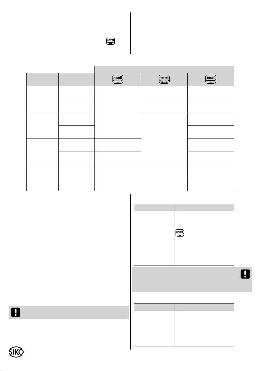
Summary of operating modes and key functions
operating
mode
absolute
measure-
ment
incremental
measure-
ment
input
offset value
ERROR
state
actuation time
<1 sec.
> 2 sec.
< 1 sec.
> 2 sec. calibrate
< 1 sec.
> 2 sec.
< 1 sec.
> 2 sec. calibrate
switch LCD on/ off
(depending on
parameter
LC-display mode)
decrement
offset value
Offset value
"-" fast mode
switch LCD on/off
(depending on
parameter
LC-Display Mode
key
Switching to
incremental measure
Switching to
offset value input
Switching to
absolute measure
no function
Calibrate if
Reset Delay OFF
calibrate
Calibrate if
Reset Delay OFF
increment
offset value
Offset value
"+" fast mode
Calibrate if
Reset Delay OFF
7. Programming the user parameters
The electronic display is programmed by means of
a hand device available from SIKO as an accessory
called "PTM". for programming, the programming
plug must be plugged into the ports through the
opening on the rear side of the MA508. In order
to ensure electrical contact, the plug should be
slightly bent. After configuring the parameters
in the "PTM" as desired (see User information
"PTM"), they can be transmitted to the electronic display. Following successful transmission, the
position value of the MA508 is at "0" and the device is in the operating mode "Absolute measure".
After programming, the offset value = 0, and the
calibration point deleted.
Display MA508 is pre-programmed to standard values at the factory.
Attention! These values are not identical with the
"PowerOn" default values.
10 MA508 Datum 11.03.2008 Art.Nr. 83093 Änd. Stand 77/08
Summary of the pre-programmed standard values:
Parameter Value
LC-Display mode Display switches off and is
reactived either by a sensor
movement or by pressing key
.
resolution 0,1 mm
decimal point 0.0
counting direction positive
Reset Delay off
Attention! While the LC display is off, the programmed parameters remain valid. However, if the
voltage supply to the battery is interrupted, all parameters will be reset to the "PowerOn" defaults.
Summary of the "PowerOn" default values:
Parameter Value
LC-Display mode display always on
resolution 0,1 mm
decimal point 0.0
counting direction positive
Reset Delay off
Page 11
8. Parameter Description
Below, all parameters and functions of the electronic display are explained. The column "Menu text
PTM" showns the allocated text display. For this
purpose, the operating mode "PCon" is selected in
the PTM (see User information "PTM").
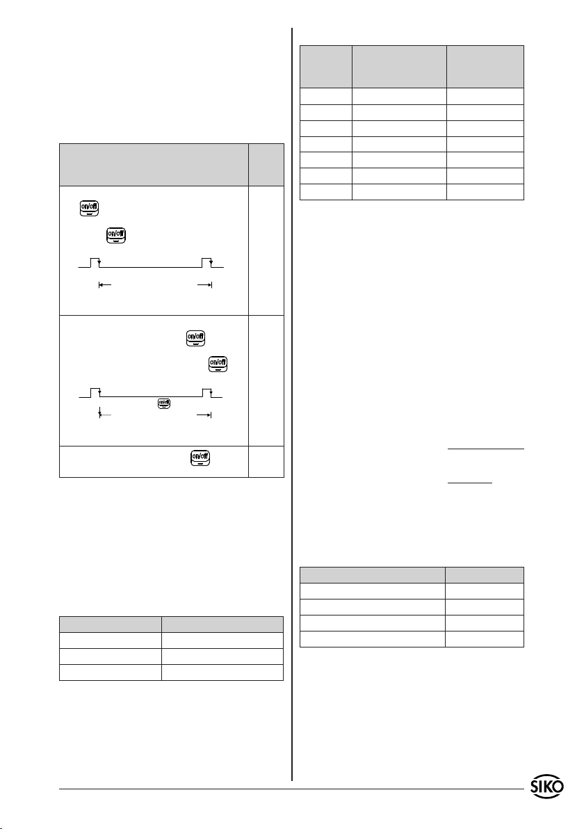
8.1 LC-Display Mode
Description Menu
The user wakes the LC display by pressing
the key. The LC display is automatically switched off after the next actuation of the key of after 15 minutes of
inactivity.
LCD
ON
LC-Display LC-Display ON
OFF
switch off
after 15 min.
The LC display appears with sensor movements* or by pressing the key. The
LC display is automatically switched off
after the next actuation of the key
or after 15 minutes of inactivity.
LCD
ON with movement or
LC-Display LC-Display ON
key
switch off
after 15 min.
LC display is olways on. The key has
no effect.
* The condition sensor movement is met as soon,
as the sensor was moved by at least 2.5 mm and no
"ERROR" status exists (see chapter 7.4 ERROR).
Accordingly, there is inactivity when the sensor
has not been moved by 2,5mm within approx.
15min. The LC display will then be switched off.
8.2 Auflösung
8.2.1 Lineare Messung:
Resolution Menu text PTM
0,1mm IP.50
1mm IP. 5
10mm IP.0.5
text
PTM
"Lc.tA"
or
"Lc.SE"
OFF
or
"Lc.On"
8.2.2 Rotative Measurement:
Resolution Description
(displayed value
after 100mm)
Menu text PTM
Interpolation
steps per pole
0,1mm 1000 IP.50
10mm* 10 IP.0.5
5mm* 20 IP. 1
2,5mm* 40 IP. 2
2mm* 50 IP.2.5
1,25mm* 80 IP. 4
1mm* 100 IP. 5
* These Stages are intended for rotative applications to account for the factor spindle pitch in the
electronic display.
Calculation of the displayed value
display value = number
of poles
x Interpolation
steps per pole
Example:
Spindle pitch: 4mm / Umdrehung
scale magnetic ring with 20 poles
After 10 revolutions (i.e. 40mm in the travel direction) the value 40.0 shall be indicated on the
display. The measuring systems senses 10 x 20 poles (= 200 poles) over this distance.
Interpolationsschritte pro Pol =
display value
number of poles
400
=
200
= 2
This corresponds to a resolution of 2,5mm.
8.3 Position of the decimal point
Description Menu text PTM
no decimal point "dP. 0"
1 Decimal place: "0.0" "dP. 1"
2 Decimal place: "0.00" "dP. 2"
3 Decimal place: "0.000" "dP. 3"
The position of the decimal place is only used for
being indicated on the display and is not considered for the calculation.
MA508 Datum 11.03.2008 Art.Nr. 83093 Änd. Stand 77/08 11
Page 12
8.4 Counting direction (see mechanical mounting)
Description Menu text PTM
Positive counting "Zr.uP"
Negative counting "Zr.dn"
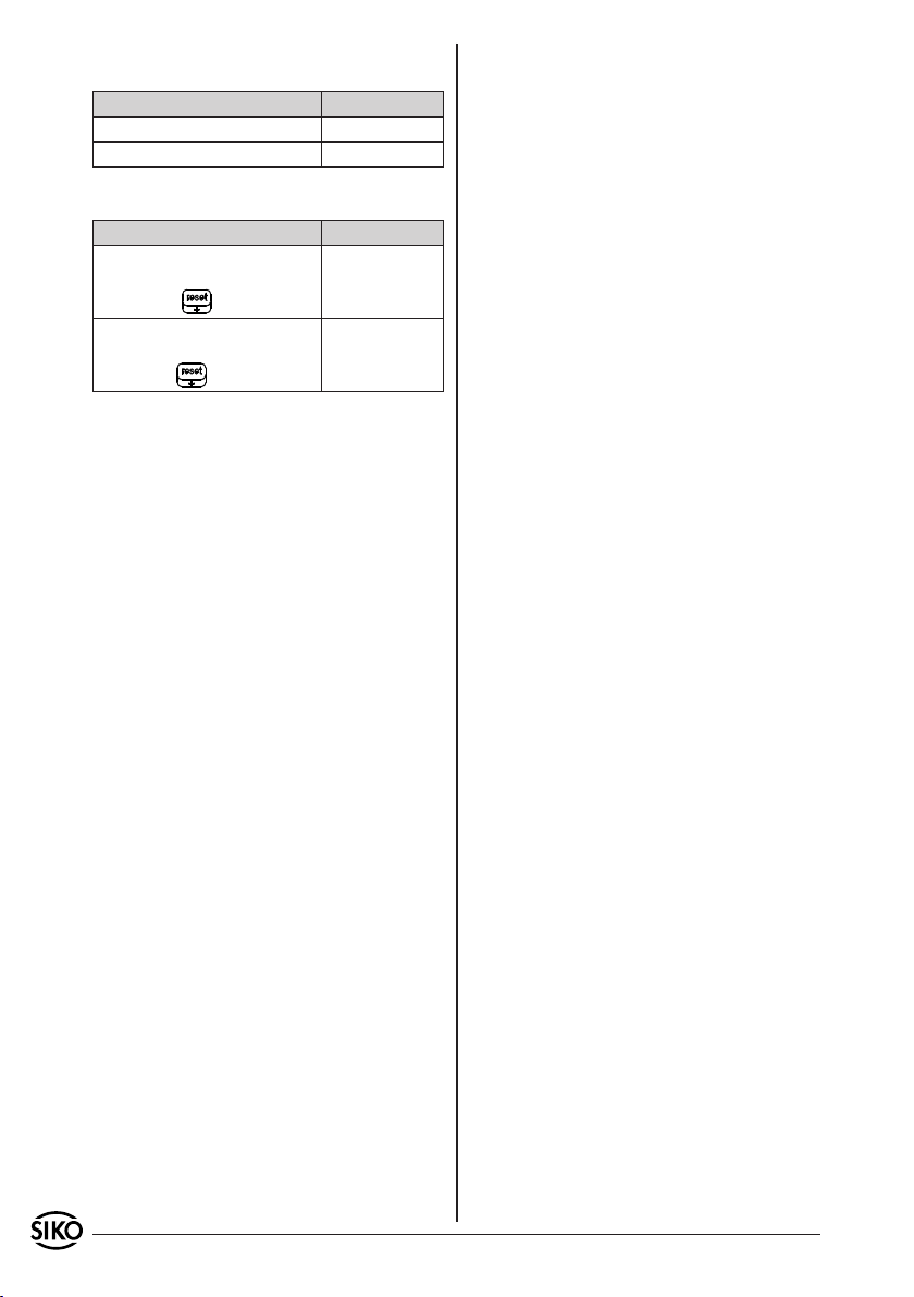
8.5 Reset Delay
Description Menu text PTM
The reset function of the MA508
is triggered after short actuating of the key (< 1 sec.).
The reset function of the MA508
is triggered after longer actuating of the key (> 2 sec.).
"rd.no"
"rd.On"
9. Trouble shooting
Error description:
"ERROR" display cannot be deleted.
•
Possible causes / remedy:
Distance or angle between active sensor surface
•
and magnetic strip is outside the mounting
tolerances.
Error description:
Displayed value does nor correspond to the posi-
•
tion after calibration of the system and traveling
of the sensor.
Possible causes / remedy:
Control resolution parameter and check whether
•
it is usable for the application.
Optimize distance or angle between sensor surface
•
and magnetic strip.
Error description:
The battery symbol appears after switching on
•
the LC display.
Possible causes / remedy:
Send device to SIKO for battery replacement.
•
12 MA508 Datum 11.03.2008 Art.Nr. 83093 Änd. Stand 77/08
Page 13
3
5
Informations pour
l‘utilisateur
MA508
Bande magnétique Affichage des mesures
FRANÇAIS
1. Consignes de garantie
Lisez ce document attentivement avant le montage
•
et la mise en service. Pour votre sécurité et pour la
sécurité de fonctionnement de l‘appareil, respectez
tous les avertissements et conseils.
Votre produit a quitté notre usine après un con-
•
trôle de son parfait état de fonctionnement. Les
spécifications données et les indications portées
sur la plaque signalétique sont les garantes de
son bon fonctionnement.
Les droits à garantie ne concernent que les
•
produits de la société SIKO GmbH. Il n‘y a pas
droit à garantie pour l‘ensemble du système en
cas d‘utilisation de produits autres.
Les réparations ne doivent être effectuées qu‘en
•
usine. La société SIKO GmbH est à votre disposition
pour tous renseignements.
d‘utilisation de plusieurs années. L‘appareil permet
un mesurage d‘angle ou de distance quasi absolu.
Les bandes magnétiques ou les bagues magnétiques servent de référence avec une longueur de
borne de 5 mm. La valeur de position est affichée
sur un écran LCD à 5 chiffres.
4. Montage mécanique
Le montage doit être effectué conformément à la
catégorie de protection IP indiquée. Le système
doit être le cas échéant protégé contre des conditions environnantes nocives, comme par exemple
projections d‘eau, dissolvants, poussière, chocs,
vibrations et fortes variations de températures.
Attention! Il faut éviter l‘influence de champs
magnétiques. En particulier, aucun champ magnétique (ex: aimants magnétiques ou autres aimants
permanents) ne doit entrer en contact direct avec
la bande magnétique.
Les critères suivants conduisent à la suppression
de la garantie:
Démontage de l‘affichage (dans la mesure où cela
•
n‘est pas décrit expressément dans la présente
information pour l‘utilisateur).
Chocs sur le boîtier ou sur le clavier à effleurement,
•
car ils peuvent entraîner des détériorations de
composants internes.
Mauvaise fixation de l‘affichage.
•
Stockage et utilisation de l‘affichage dans des
•
conditions environnementales non prévues.
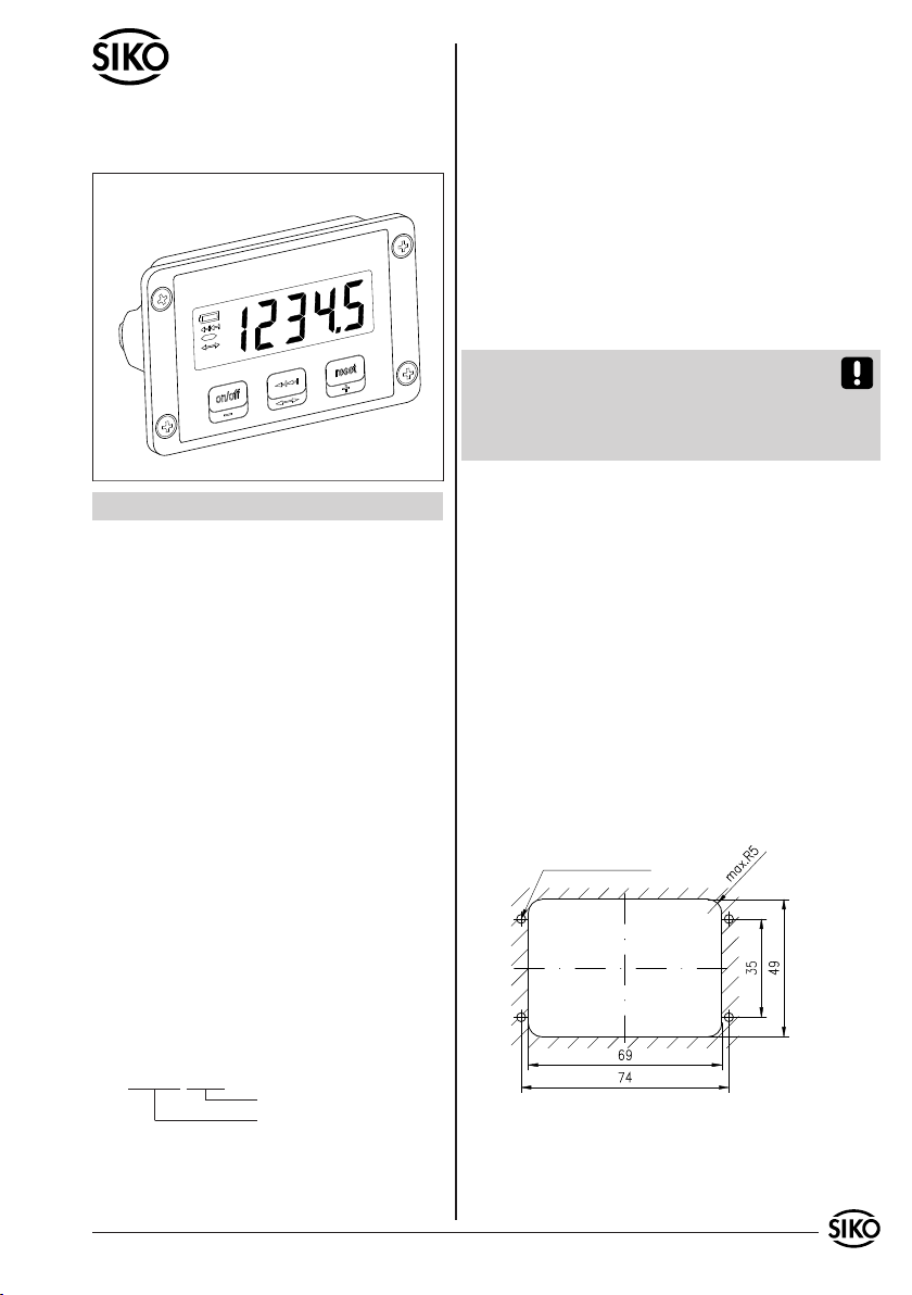
4.1 Montage de l‘affichage
Le boîtier peut être fixé dans un encastrement
•
pour tableau de distribution au moyen de 4
orifices de montage.
pour filetage M3
2. Identification
La plaque signalétique indique le modèle d‘appareil
avec le numéro de variante. Les documents de livraison attribuent à chaque numéro de variante une
description de commande détaillée.
Ex: MA508-0023
N° de variante
Modèle de l‘appareil
3. Description sommaire
L‘affichage MA508 est un système de mesure
autonome. La pile intégrée garantit une durée
MA508 Datum 11.03.2008 Art.Nr. 83093 Änd. Stand 77/08 13
Ill 1: Encastrement pour tableau de distribution
4.2 Montage détecteur magnétique:
Les distances d‘écartement entre la surface active
•
du détecteur et la bande magnétique ainsi que
les tolérances angulaires doivent être respectées,
Page 14
et ce, sur toute la longueur de la distance de
mesure.
Une erreur de mesure dans les limites des écarts
•
de position définis est négligeable.
Il faut éviter une addition des tolérances de
•
montage à tous les niveaux.
En cas de détecteur externe, le câble de raccor-
•
dement doit être posé de manière à ce qu‘il n‘y
ait aucun danger de détérioration par d‘autres
éléments de la machine ou par une force de
traction.
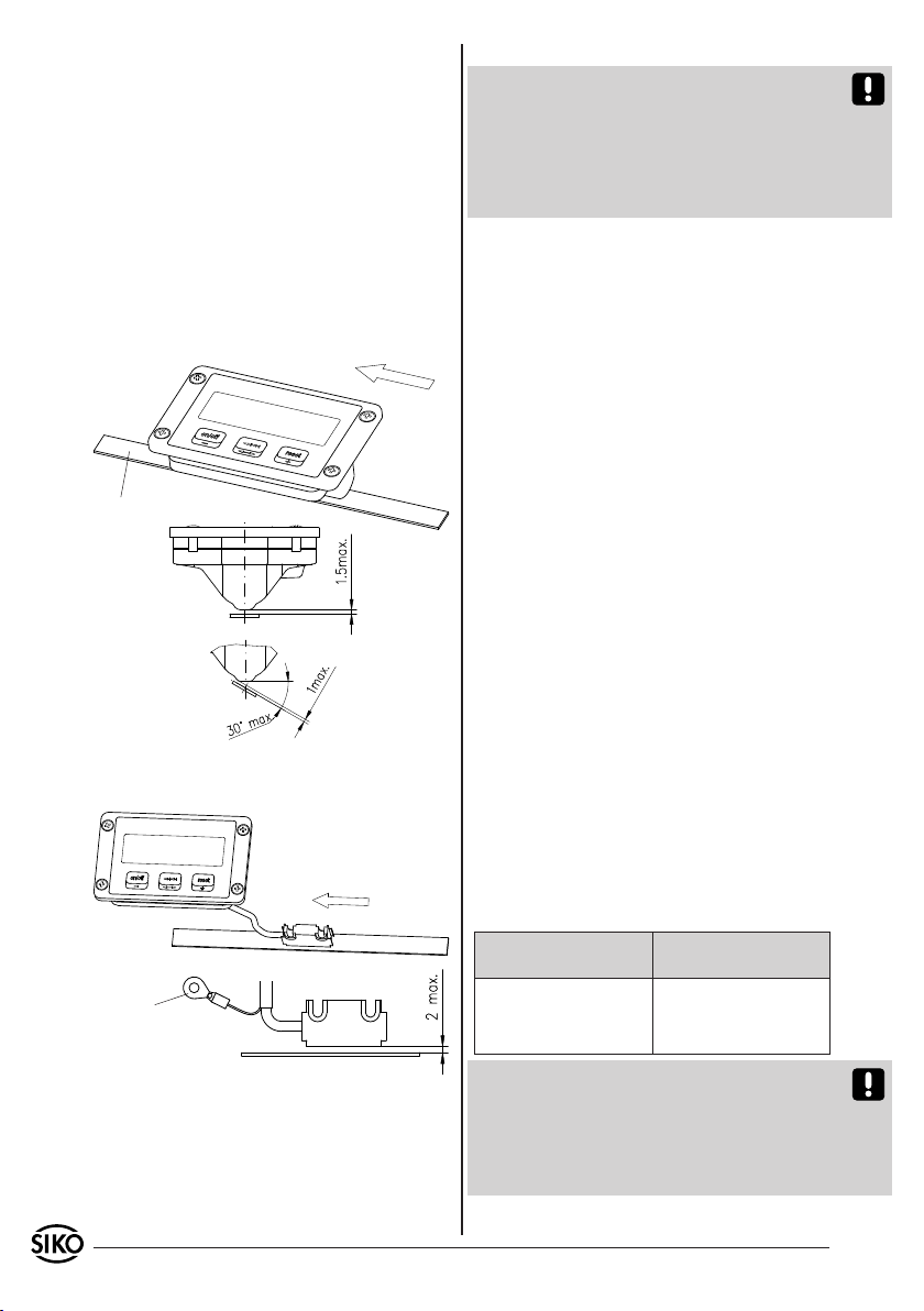
4.2.1 Modèle de détecteur Détecteur intégré (IS):
Sens de déplacement:
Sens de comptage positif
Bande magnétique
Ill 2: Tolérance de montage Détecteur interne
4.2.2 Modèle de détecteur Détecteur externe (ES):
Sens de déplacement:
Sens de comptage positif
manière fixe avec l‘affichage.
Attention! Le câble de raccordement du détecteur
magnétique ne doit pas être séparé ou prolongé!
Etant donné que chaque affichage est explicitement règle en fonction du détecteur branché, un
échange ne peut être effectué qu‘en usine (par
exemple après une rupture de câble ou une détérioration mécanique du détecteur).
Conseils pour l‘insensibilité aux parasites
L‘emplacement de l‘affichage doit être choisi
de manière à ce que des perturbations inductives ou capacitives ne puissent intervenir sur
l‘affichage ou sur ses câbles de branchement!
Les influences de parasites (ex éléments du réseau
de distribution, moteurs, régulateurs ou protections synchronisés) peuvent être réduites par un
circuit de câblage approprié.
Mesures appropriées:
Le système doit être monté le plus loin possible
•
de conduites présentant des parasites. Le cas
échéant, des mesures supplémentaires doivent
être prévues, comme des écrans de protection
ou des boîtiers métalliques. Eviter des câblages
parallèles aux conduites de transport d‘énergie.
Les bobines de protection doivent être câblées
•
avec des étouffeurs d‘étincelles.
Pour les longueurs de câble de détecteur >
•
0,3m, le boîtier de l‘affichage et le raccord PE du
détecteur (voir ill. 3) doivent être correctement
mis à la terre!
Alimentation électrique
Le contrôle automatique de l‘état de charge assure un comptage sûr pendant plusieurs années,
même lorsque l‘écran LCD est éteint. La durée
d‘utilisation dépend principalement de la durée de
fonctionnement sélectionnée de l‘écran LCD. Les
valeurs de référence peuvent être les suivantes:
Raccord PE
(Cosse de câble pour M3
uniquement pour une longueur de câble de détecteur >0,3m)
Ill 3: Tolérance de montage Détecteur externe
5. Branchement électrique
Aucune installation électrique de branchement
n‘est nécessaire étant donné que l‘appareil est
Durée de
fonctionnement
100% env. 6 ans
40% env. 9 ans
20% > 10 ans
Attention! Dès que la tension de la pile se situe
en dessous d‘une valeur seuil définie, un symbole
apparaît à l‘affichage. A ce stade, le fonctionnement de l‘affichage est garanti pour une certaine
période mais la pile devrait être changée le plus
rapidement possible auprès de SIKO.
Durée de vie des
piles
alimenté de manière autonome par une pile au
lithium intégrée et que le détecteur est relié de
14 MA508 Datum 11.03.2008 Art.Nr. 83093 Änd. Stand 77/08
Page 15
6. Manipulation et modes de fonctionnement
La manipulation de l‘affichage ou le changement
de mode de fonctionnement s‘effectuent au moyen des trois touches à effleurement frontales. Les
touches peuvent disposer de fonctions supplémentaires selon le mode de fonctionnement. Elles ont
une action individuellement et en fonction de la
durée d‘actionnement.
Retour au mode de fonctionnement "Mesure
absolue":
A appuyant de nouveau sur la touche . Les
modifications du paramètre de position sont prises
en compte.
Attention! Une pression de la touche en
mode de fonctionnement "Mesure incrémentale"
actionne également le passage en mode "Mesure
absolue". L‘affichage est alors recalibré en même
temps.
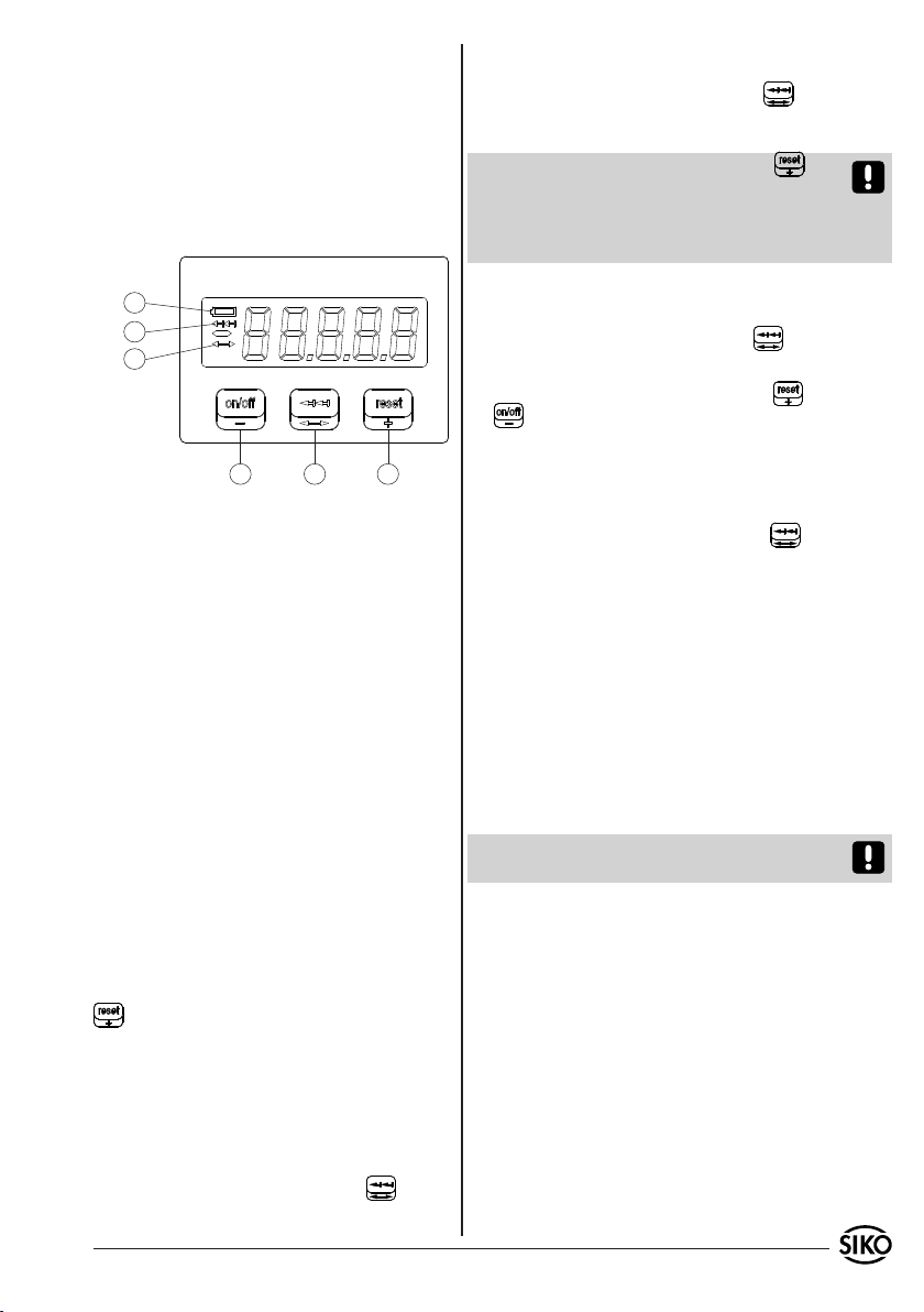
1
2
3
54
Affichage batterie faible
1.
Affichage mesure incrémentale activée
2.
Affichage saisie valeur offset
3.
-Allumer / Eteindre écran LCD
4.
-décrémenter valeur offset
-Mesure incrémentale
5.
-Saisie offset
-Réinitialisation / Calibrage
6.
-Incrémenter valeur offset
6.1 Mesure absolue
Après la mise en service, l‘affichage se trouve en
mode de fonctionnement "Mesure absolue". Le paramètre de position calculé est affiché (voir calcul
des valeurs d‘affichage).
Il est nécessaire de calibrer le système de mesure
dans les cas suivants:
Après la première mise en service
•
Après un changement de pile Back Up
•
Dans le cas où le détecteur se trouve dans une
•
position située en dehors des tolérances de
montage.
Le calibrage s‘effectue en appuyant sur la touche
qui réinitialise le paramètre de position (par
défaut = 0). La touche réagit à une pression brève
ou en différé en fonction du paramètre "Reset Delay".
6.2 Mesure incrémentale
Changement en mode de fonctionnement "Mesure incrémentale".
En appuyant brièvement sur la touche . La valeur "0" apparaît alors à l‘affichage.
6
6.3 Saisie offset
Entrée en mode de fonctionnement "Saisie Offset":
En appuyant longuement sur la touche .
Programmation de la valeur Offset:
Modification de la valeur avec les touches (+)
et (-). En appuyant brièvement, la valeur est
modifiée d‘un incrément, en appuyant plus longtemps (avance rapide), les chiffres augmentent ou
diminuent en mode rapide.
Mémorisation de la valeur Offset programmée:
En appuyant de nouveau sur la touche . La
modification est enregistrée et le mode de fonctionnement bascule de nouveau sur "Mesure absolue". Une fois que les paramètres d‘affichage sont
programmés (voir chapitre 7 Programmation des
paramètres utilisateur) ou après un "PowerOn"
(changement de pile), la valeur Offset est égale
à 0.
6.4 ERROR
En position "ERROR", le MA 508 est déplacé indépendamment du fait que l‘écran soit ou non allumé
ou éteint. Lorsque l‘écran est allumé, l‘état "ERROR" est signalé à l‘écran par ce même mot.
Attention! Dès que l‘état "ERROR" apparaît, les
modifications de position ne sont plus saisies.
Causes possibles de l‘état "ERROR":
L‘écart entre la bande magnétique et la surface
1.
du détecteur se trouve en dehors de la tolérance
de montage. -> Contrôle et le cas échéant réglage
de l‘alignement et des tolérances de montage
détecteur magnétique / bande.
Si le compteur absolu dépasse la valeur +99´999
2.
ou si la valeur -99´999 n‘est pas atteinte, la valeur
"FULL" s‘affiche si l‘écran est allumé. Les modifications de position continuent à être comptées
en interne. Dès que le compteur interne dépasse
cependant la valeur ±180´000, l‘affichage bascule
en mode de fonctionnement "ERROR".
-> En cas de dépassement de la plage des valeurs,
le paramètre Etapes d‘interpolation/Pôle doit
MA508 Datum 11.03.2008 Art.Nr. 83093 Änd. Stand 77/08 15
Page 16
être réduit (voir Description des paramètres:
définition ou étapes d‘interpolation / pôle).
La vitesse de déplacement maximum possible
3.
du détecteur a été dépassée.
-> Réduire la vitesse
Suppression de l‘état "ERROR":
Brancher l‘écran (touche ), positionner le
détecteur sur le point de calibrage et actionner
la touche .
Le paramètre "Reset Delay" permet de déterminer
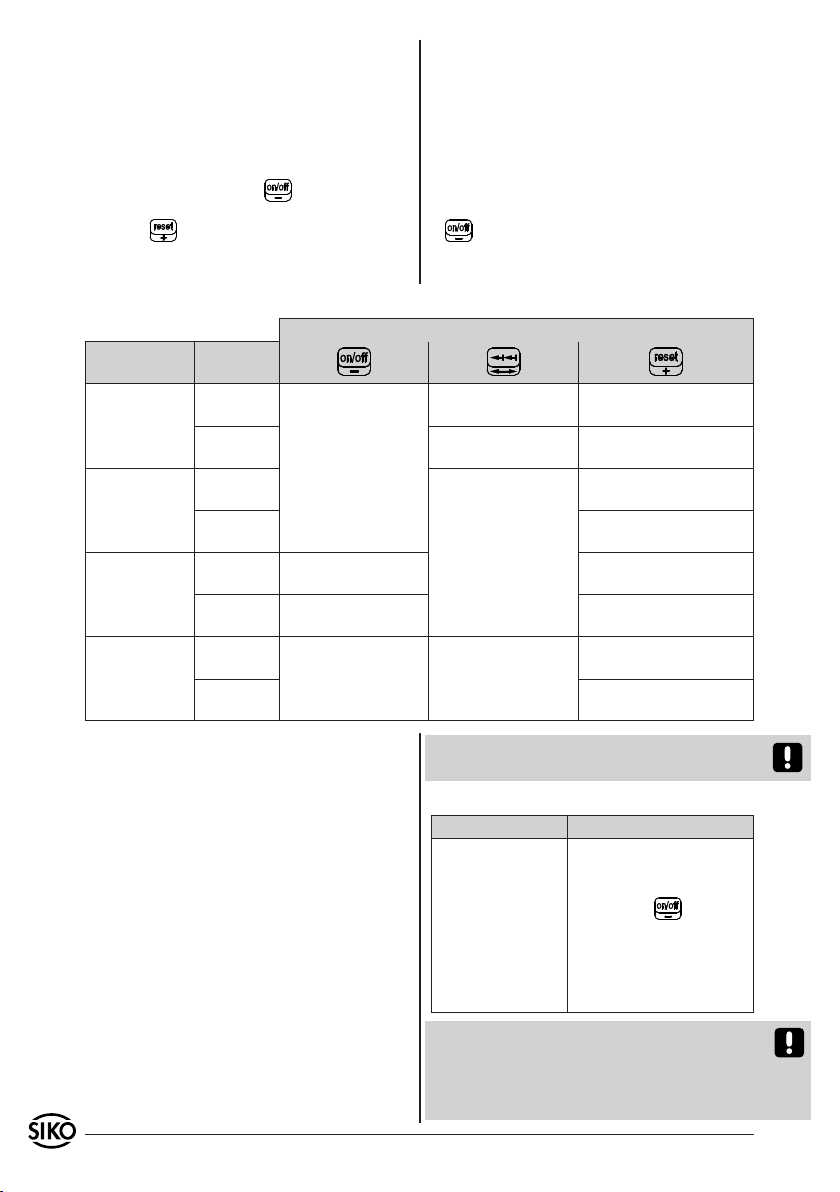
Résumé des modes de fonctionnement et des touches de fonction
Mode de fonc-
tionnement
Saisie Offset
Mesure
incrémental
Saisie Offset
Etat
ERROR
Durée
d‘action
< 1 sec.
> 2 sec.
< 1 sec.
> 2 sec. Calibrage
< 1 sec.
> 2 sec.
< 1 sec.
> 2 sec. Calibrage
Brancher / débran-
cher écran
(en fonction du pa-
ramètre Mode écran)
Décrémenter la
valeur Offset
Valeur offset "-"
Avance rapide
Brancher / débran-
cher écran
(en fonction du pa-
ramètre Mode écran)
si la touche réagit à une action brève ou seulement au bout de 2 secondes environ (protection
contre les contacts accidentels).
Si le mode d‘affichage "Ecran en permanence allumé" ("Lc.On") n‘a pas été programmé, l‘état "ERROR" intervient directement sur le comportement
de l‘affichage (voir chapitre 8 - Description des
paramètres:
Le branchement n‘est possible qu‘avec la touche
•
.
Les mouvements du détecteur ne sont plus
•
exploité.
Touche
Bascule en mesure
incrémentale
Bascule en saisie
Offset
Bascule en mesure
absolue
Aucune fonction
Calibrage si réinitialisati-
on Reset Delay sur OFF
Calibrage
Calibrage si réinitialisati-
on Reset Delay sur OFF
Incrémenter la valeur
Offset
Valeur offset
"+" Avance rapide
Calibrage, si réinitialisa-
tion Reset Delay sur OFF
7. Programmation des paramètres
utilisateur
La programmation de l‘affichage s‘effectue au moyen d‘un appareil manuel, disponible comme accessoire chez SIKO sous la désignation "PTM". Pour la
programmation, la fiche de programmation doit être
branchée dans les raccordements par l‘orifice situé
à l‘arrière du MA508. Pour établir le contact électrique, la fiche doit être légèrement penchée. Une
fois que les paramètres ont été configurés selon
les besoins dans le "PTM" (voir information pour
l‘utilisateur "PTM"), ils peuvent être transférés à
l‘affichage. Une fois le transfert effectué, la valeur
de position du MA508 est sur "0" et l‘appareil se
trouve en mode de fonctionnement "Mesure absolue". Après la programmation, la valeur Offset est
égale à 0, et le point de calibrage est effacé.
L‘affichage est livré départ usine avec une programmation standard.
16 MA508 Datum 11.03.2008 Art.Nr. 83093 Änd. Stand 77/08
Attention! Ces valeurs ne sont pas identiques aux
valeurs par défaut "PowerOn".
Résumé des réglages usine:
Paramètre Valeur
Mode écran LCD L‘écran s‘éteint et se rallu-
me avec un mouvement du
détecteur ou une pression
de la touche .
Résolution 0.1 mm
Virgule décimale 0.0
Sens de comptage Positif
Reset Delay Arrêt
Attention! Lorsque l‘écran est éteint, les paramètres programmés sont conservés. Cependant, si
l‘alimentation de la pile devait être interrompue,
l‘ensemble des paramètres sera déplacé sur les valeurs par défaut "PowerOn".
Page 17
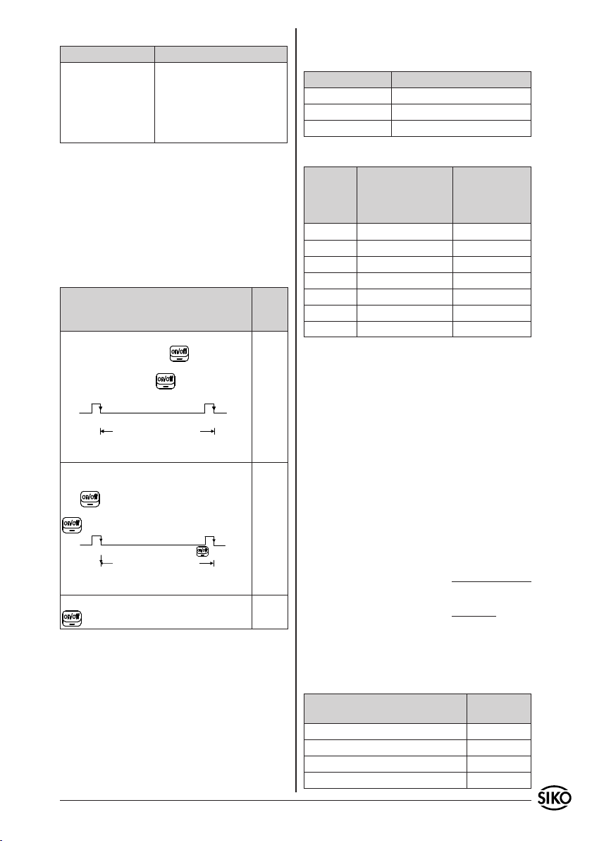
Résumé des valeurs par défaut "PowerOn":
Paramètre Valeur
Mode écran LCD Ecran toujours allumé
Résolution 0.1 mm
Virgule décimale 0.0
Sens de comptage Positif
Reset Delay Arrêt
8. Description des paramètres
Tous les paramètres d‘affichage et leurs fonctions
sont expliqués ci-après. Dans la colonne "Texte menu
PTM", le texte affiché du PTM est présenté. Pour cela,
le mode de fonctionnement "PCon" doit être sélectionné au PTM (voir information pour l‘utilisateur
"PTM").
8.1 Mode écran LCD
Description Texte
L'utilisateur rallume l'écran LCD avec une
pression de la touch . L'écran LCD
s‘éteint automatiquement avec la pression
suivante de la touche ou au bout de 15
mn d'inactivité.
LCD
Marche
Ecran LC L‘écran allumé
Arrêt
L'écran LCD apparaît avec un mouvement
du détecteur* ou une pression de la touche . L'écran LCD s‘éteint automatiquement avec la pression suivante de la touche
ou au bout de 15 mn d'inactivité.
LCD
Marche avec mouvement ou touche
Ecran LC L‘écran allumé
de 15 mn
L‘écran est toujours allumé. La touche
n‘a aucune action.
* La condition Mouvement du détecteur est remplie
dès que le détecteur se déplace d‘au moins 2,5mm
et qu‘il n‘y a pas de message "ERROR" (voir chapitre 7.4 Error). Il n‘y a en revanche aucune activité
lorsque le détecteur ne se déplace pas d‘au moins
2,5mm pendant environ 15 minutes. L‘écran LCD
s‘éteint alors.
ou éteint
au bout
de 15 mn
Arrêt
ou éteint
au bout
menu
PTM
"Lc.tA"
"Lc.SE"
"Lc.On"
8.2 Résolution
8.2.1 Mesurage linéaire:
Résolution Texte menu PTM
0,1mm IP.50
1mm IP. 5
10mm IP.0.5
8.2.2 Mesurage rotatif:
Résolution Description
(valeur affichée à
l‘écran au bout de
100 mm)
Texte menu
PTM Etape
interpolation
par pôle
0,1mm 1000 IP.50
10mm* 10 IP.0.5
5mm* 20 IP. 1
2,5mm* 40 IP. 2
2mm* 50 IP.2.5
1,25mm* 80 IP. 4
1mm* 100 IP. 5
* Ces étapes ne sont prévues que pour les applications rotatives, pour tenir compte à l‘affichage du
facteur pas de broche.
Calcul de la valeur d‘affichage
Valeur
d‘affichage
= Nombre
de pôles
x Etape d‘inter-
polation par pôle
Exemple:
Pas de broche: 4mm / tour
Echelle: Bague magnétique avec 20 pôles
Au bout de 10 tours (c‘est-à-dire 40 mm dans le
sens du déplacement), la valeur 40.0 doit apparaître à l‘affichage. Le système de mesure saisit sur
cette distance 10 x 20 pôles (= 200 pôles).
Etapes d‘interpolation par pôle =
Valeur d‘affichage
Nombre de pôles
400
=
200
= 2
Cela correspond à une résolution de 2,5mm.
8.3 Position du virgule décimal
Description Texte menu
PTM
Pas de virgule décimale "dP. 0"
1 chiffre après la virgule: "0.0" "dP. 1"
2 chiffre après la virgule: "0.00" "dP. 2"
3 chiffre après la virgule: "0.000" "dP. 3"
MA508 Datum 11.03.2008 Art.Nr. 83093 Änd. Stand 77/08 17
Page 18
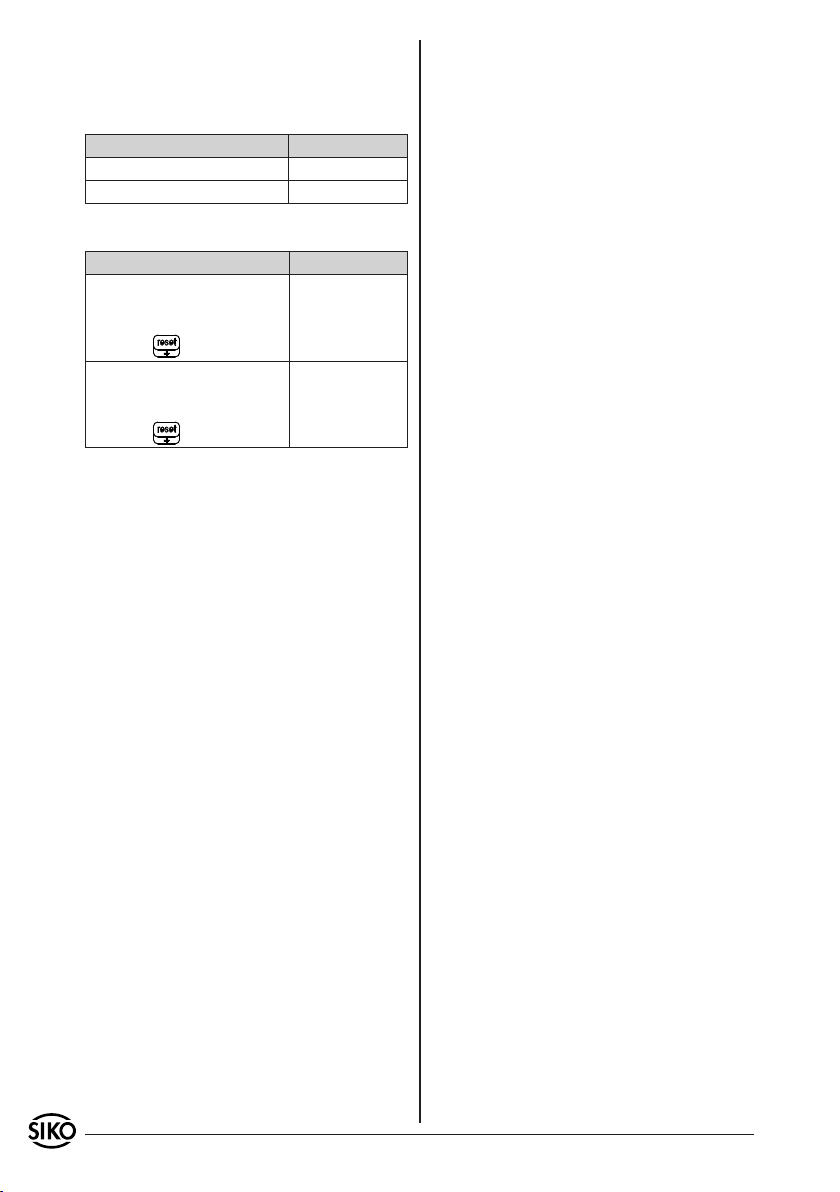
La position de la virgule décimale n‘est utilisée
que pour la présentation à l‘écran et n‘intervient
pas dans le calcul.
8.4 Sens de comptage (voir Montage mécanique)
Description Texte menu PTM
Mode de comptage positif "Zr.uP"
Mode de comptage negatif "Zr.dn"
8.5 Reset Delay
Description Texte menu PTM
La fonction réinitialisation du
MA508 se déclenche en actionnant brièvement (< 1 sec.)
la touche .
La fonction réinitialisation du
MA508 se déclenche en actionnant longuement (> 2 sec.)
la touche .
"rd.no"
"rd.On"
9. Dépannage
Description de la panne:
L‘affichage "ERROR" ne peut être effacé.
•
Causes possibles / remède:
Ecartement ou angle entre la surface active du
•
détecteur et la bande magnétique en dehors des
limites de tolérance du montage.
Description de la panne:
La valeur affichée ne correspond pas à la posi-
•
tion une fois que le système a été calibré et le
détecteur déplacé.
Causes possibles / remède:
Contrôler le paramètre Résolution et vérifier s‘il
•
est utilisable pour l‘application en cours.
Optimiser l‘écart ou l‘angle entre la surface du
•
détecteur et la bande magnétique.
Description de la panne:
Le symbole Pile apparaît lorsque l‘écran
•
s‘allume.
Causes possibles / remède:
Envoyer l‘appareil à SIKO pour changer la pile.
•
18 MA508 Datum 11.03.2008 Art.Nr. 83093 Änd. Stand 77/08
Page 19

MA508 Datum 11.03.2008 Art.Nr. 83093 Änd. Stand 77/08 19
Page 20

SIKO GmbH
Werk / Factory:
Weihermattenweg 2
79256 Buchenbach-Unteribental
Postanschrift / Postal address:
Postfach 1106
79195 Kirchzarten
Telefon/Phone +49 7661 394-0
Telefax/Fax +49 7661 394-388
E-Mail [email protected]
Internet www.siko.de
Service [email protected]
20 MA508 Datum 11.03.2008 Art.Nr. 83093 Änd. Stand 77/08
 Loading...