

Page 1
Benutzerinformation
MA505
Magnetbandanzeige absolut
DEUTSCH
ratur geschützt werden.
Achtung! Systeminfo! Nur bei Sensoranschluss
MSA! Beachten Sie bei der Montage eines Sensors
oder des Magnetbandes den im Kapitel 6 (Sensorabgleich) angegebenen notwendigen Abgleichweg
und die richtige Ausrichtung beider Systemkomponenten zueinander.
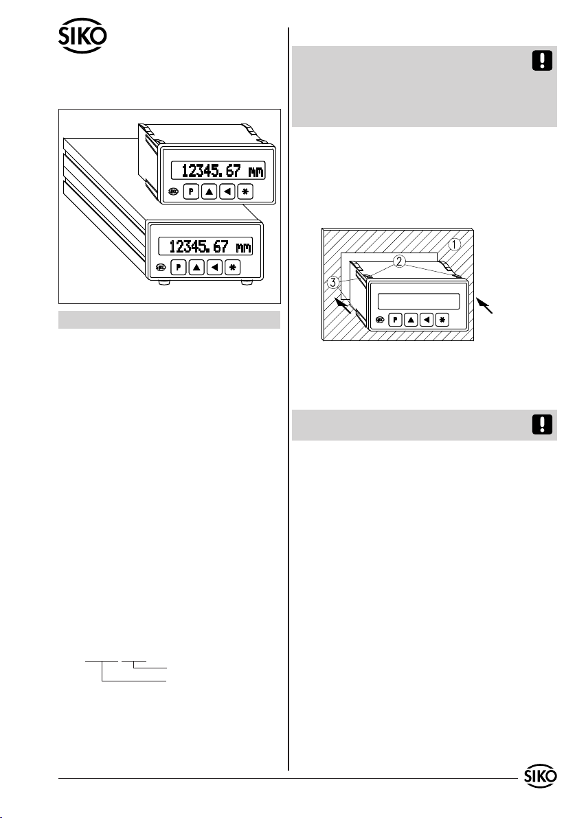
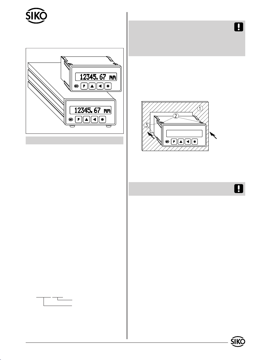
Einbaugehäuse EG
Gerät in Schalttafelausschnitt (1) schieben bis die
•
Panel-Clips (2) das Gehäuse lose halten.
Die seitliche Zentrierung (3) leicht andrücken und
•
das Gehäuse in den Ausschnitt (1) schieben bis
die Panel-Clips (2) vollständig einrasten.
1. Gewährleistungshinweise
Lesen Sie vor der Montage und der Inbetriebnahme
•
dieses Dokument sorgfältig durch. Beachten Sie zu
Ihrer eigenen Sicherheit und der Betriebssicherheit
alle Warnungen und Hinweise.
Ihr Produkt hat unser Werk in geprüftem und be-
•
triebsbereitem Zustand verlassen. Für den Betrieb
gelten die angegeben Spezifikationen und die
Angaben auf dem Typenschild als Bedingung.
Garantieansprüche gelten nur für Produkte der
•
Firma SIKO GmbH. Bei dem Einsatz in Verbindung
mit Fremdprodukten besteht für das Gesamtsystem
kein Garantieanspruch.
Reparaturen dürfen nur im Werk vorgenommen
•
werden. Für weitere Fragen steht Ihnen die Firma
SIKO GmbH gerne zur Verfügung.
2. Identifikation
Das Typenschild zeigt den Gerätetyp mit Variantennummer. Die Lieferpapiere ordnen jeder Variantennummer eine detaillierte Bestellbezeichnung zu.
z.B. MA505-0023
Varianten-Nr.
Geräte-Typ
3. Mechanische Montage
Die Montage darf nur gemäß der angegebenen IPSchutzart vorgenommen werden. Die Anzeige muss
ggfs. zusätzlich gegen schädliche Umwelteinflüsse, wie z.B. Spritzwasser, Staub, Schläge, Tempe-
MA505 Datum 25.09.2008 Art.Nr. 80475 Änd. Stand 369/08 1
Abb. 1: Einbau
Tischgehäuse TG, TG/DV
Zum Anschrauben des Gerätes können die Gummifüße entfernt werden.
Achtung! Die max. Einschraubtiefe von 6,5mm
darf nicht überschritten werden!
4. Elektrischer Anschluss
Anschlussverbindungen dürfen nicht unter
•
Spannung geschlossen oder gelöst werden!
Verdrahtungsarbeiten dürfen nur spannungslos
•
erfolgen!
Litzen sind mit Aderendhülsen zu versehen.
•
Vor dem Einschalten sind alle Leitungsanschlüsse
•
und Steckverbindungen zu überprüfen.
Hinweise zur Störsicherheit
Alle Anschlüsse sind gegen äußere Störeinflüsse
geschützt. Der Einsatzort ist aber so zu wählen,
dass induktive oder kapazitive Störungen nicht
auf die Anzeige oder deren Anschlussleitungen
einwirken können! Durch geeignete Kabelfüh-
rung und Verdrahtung können Störeinflüsse (z.B.
von Schaltnetzteilen, Motoren, getakteten Reglern oder Schützen) vermindert werden.
Erforderliche Maßnahmen
Nur geschirmtes Kabel verwenden. Den Kabel-
•
schirm beidseitig auflegen. Litzenquerschnitt der
Leitungen min. 0,14mm², max. 0,5mm².
Page 2
Die Verdrahtung von Abschirmung und Masse
•
(0V) muss sternförmig und großflächig erfolgen.
Der Anschluss der Abschirmung an den Potentialausgleich muss großflächig (niederimpedant)
erfolgen.
Das System muss in möglichst großem Abstand von
•
Leitungen eingebaut werden, die mit Störungen
belastet sind; ggfs. sind zusätzliche Maßnahmen
wie Schirmbleche oder metallisierte Gehäuse
vorzusehen. Leitungsführungen parallel zu Energieleitungen vermeiden.
Schützspulen müssen mit Funkenlöschgliedern
•
beschaltet sein.
PE-Verbindung mit 2,5 – 4mm² über PE-Anschluss
•
(Bei Einbaugehäuse gemäß Abb. 2 mit Flachsteckhülse 6,3x0,8).
Spannungsversorgung
Die Spannungsversorgung erfolgt über die rückseitigen Anschlussmöglichkeiten gemäß Abb. 2 oder
Abb. 3. Die Spannungswerte sind abhängig von
der Geräteausführung und sind den Lieferpapieren
oder dem Typenschild zu entnehmen ist.
z.B.: 230 VAC ±10%
Sensoranschluss
Der Anschluss erfolgt über die 8-polige Mini-Din
Buchse an der Rückseite (Abb. 2/Abb. 6).
Achtung! Der Sensoranschluss darf nicht geändert
werden (z.B. durch Kabelverlängerungen).
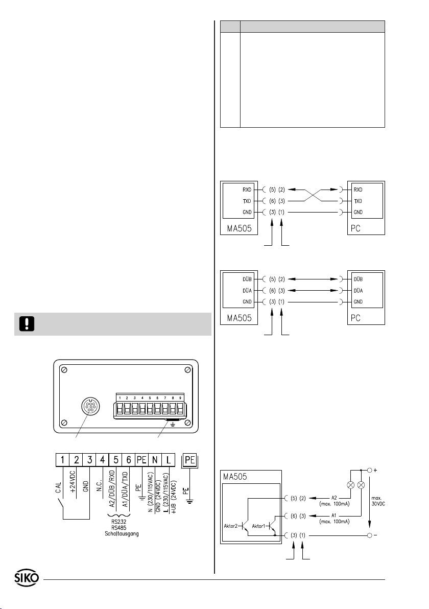
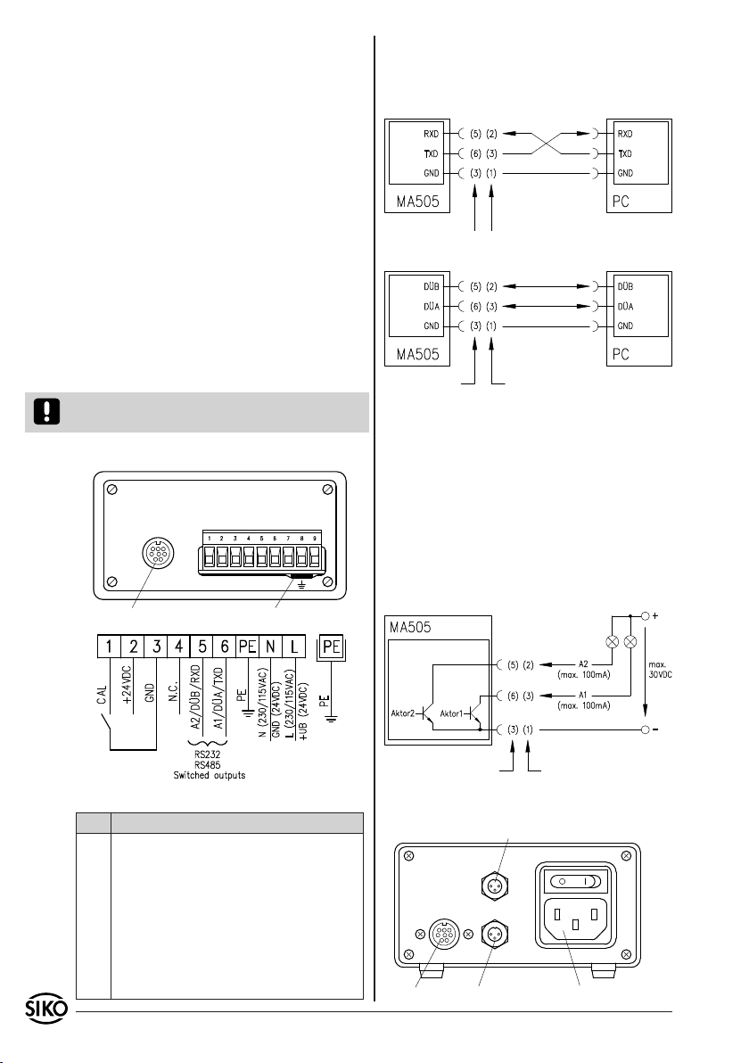
4.1 Anschluss Einbaugehäuse EG
Sensor PE Anschluss für Flachsteckhülse
Nr. Belegung
1 CAL
2 UB = +12V (für Kalibriereingang)
3 GND
4 N.C.
5 RS232 (RXD), RS485 (DÜB), A2
6 RS232 (TXD), RS485 (DÜA), A1
7 PE
8 N (230/115 VAC), GND (24 VDC)
9 L (230/115 VAC), UB (24 VDC)
4.1.1 Option serielle Schnittstelle RS232 oder RS485
Der Anschluss der seriellen Schnittstelle RS232
bzw. RS485 erfolgt über die Klemmen 3 (GND), 6
(TXD/ DÜA) und 5 (RXD/ DÜB).
Belegung
Klemmleiste EG
Belegung
Stecker TG
Abb. 3: Anschlussschema Schnittstellenoption RS232
Belegung
Klemmleiste EG
Belegung
Stecker TG
Abb. 4: Anschlussschema Schnittstellenoption RS485
4.1.2 Option Schaltausgänge
Es stehen zwei Open-Kollektor Ausgänge A1 (Klemme 6) und A2 (Klemme 5) zur Verfügung. Der gemeinsame Minuspol dieser Ausgänge ist an Klemme
3 anzuschließen. Der zulässige Spannungsbereich
ist 30 VDC, der zulässige Maximalstrom 100mA pro
Ausgang. Das Schaltverhalten dieser Ausgänge ist
programmierbar.
Positionswert > oberer Grenzwert (OGW): Aktor 1 aktiv
•
Positionswert < unterer Grenzwert (UGW): Aktor 2 aktiv
•
Abb. 2: Anschlussbelegung EG
Belegung
Klemmleiste EG
Belegung
Stecker TG
Abb. 5: Anschlussschema Option Schaltausgänge
2 MA505 Datum 25.09.2008 Art.Nr. 80475 Änd. Stand 369/08
Page 3
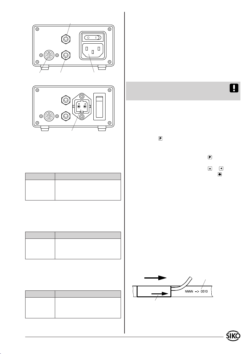
4.2 Anschluss Tischgehäuse TG, TG/DV
Schnittstelle/Schaltausgänge
Sensor Kalibriereingang Spannungsversorgung
Spannungsversorgung 24 VDC
230VAC, 115 VAC
Abb. 6: Anschlussbelegung TG, TG/DV
Option Kalibriereingang
Der Anschluss erfolgt mittels beiliegendem Kupplungsstecker an der rückseitigen Flanschdose (Abb.
6) gemäß nachfolgender Belegung.
Nr. Belegung
1 CAL
2 GND
3 UB
Option serielle Schnittstelle
Der Anschluss erfolgt mittels beiliegendem Kupplungsstecker an der rückseitigen Flanschdose (Abb.
6) gemäß nachfolgender Belegung.
Nr. Belegung
1 GND
2 RXD / DÜB
3 TXD / DÜA
Option Schaltausgänge
Der Anschluss erfolgt mittels beiliegender Kupplungsdose an dem rückseitigen Flanschstecker
(Abb. 6) gemäß nachfolgender Belegung.
Nr. Belegung
1 GND
2 A2
3 A1
5. Inbetriebnahme
Nach ordnungsgemäßem Anschluss und dem Einschalten der Betriebsspannung erfolgt:
Hardwarekennung (z.B. SIKO:MA505) ca. 1,5s
•
Anzeige des Firmware-Standes (z.B. V1.00)
•
Anzeige des Sensortyps (z.B. MSA)
•
Anzeige der Adresse (z.B. Adresse: 31) nur bei
•
Schnittstellenprotokoll SIKONETZ 3
Anschließend kann die Anzeige anwendungsspezifisch programmiert werden.
Bei Neuinstallation des Systems oder einer Komponente (Messanzeige, Sensor, Band) ist jeweils
einmalig ein Sensorabgleich notwendig.
5.1 Sensorabgleich MSA, LSA200
Beachten Sie, dass bei Montage des Systems die
Pfeilrichtung des Sensoraufdruckes mit der Pfeilrichtung des Magnetbandaufdruckes übereinstimmt
(siehe Abb. 7).
Halten Sie die -Taste für mind. 5s (Werkseinstellung) gedrückt um in den Programmiermode zu
gelangen.
Durch mehrmalige kurze Betätigung der -Taste
erreichen Sie nun den Menüpunkt "CODE". Hier
geben Sie über die beiden Pfeiltasten +
den Wert "00100" ein und bestätigen mit der Taste. Ab jetzt befinden Sie sich im automatischen
Abgleichmodus, was durch eine alternierende Anzeige von "ink", "abs" oder "Versatz" (nur LSA200)
und den entsprechenden Abgleichwerten im Display dargestellt wird.
Der Sensor muss nun in Richtung des Kabelabganges mit einer Geschwindigkeit von max.
1mm/s (LSA200) bzw. max. 10mm/s (MSA) bewegt werden. Der Abgleich ist nach ca. 20mm
beendet. In der Anzeige erscheint nun der tat-
sächliche Messwert. Geben Sie nun die notwendigen Parameter im Programmiermodus ein und
führen Sie eine Nullung/Kalibrierung durch. (Hin-
weise zur Menüführung finden Sie im Beiblatt zur
Softwarebeschreibung)
Verfahrrichtung beim Abgleich Bedruckung
Bedruckung auf Sensorunterseite (aktive Seite)
Abb. 7: Sensor MSA
auf Band
MA505 Datum 25.09.2008 Art.Nr. 80475 Änd. Stand 369/08 3
Page 4
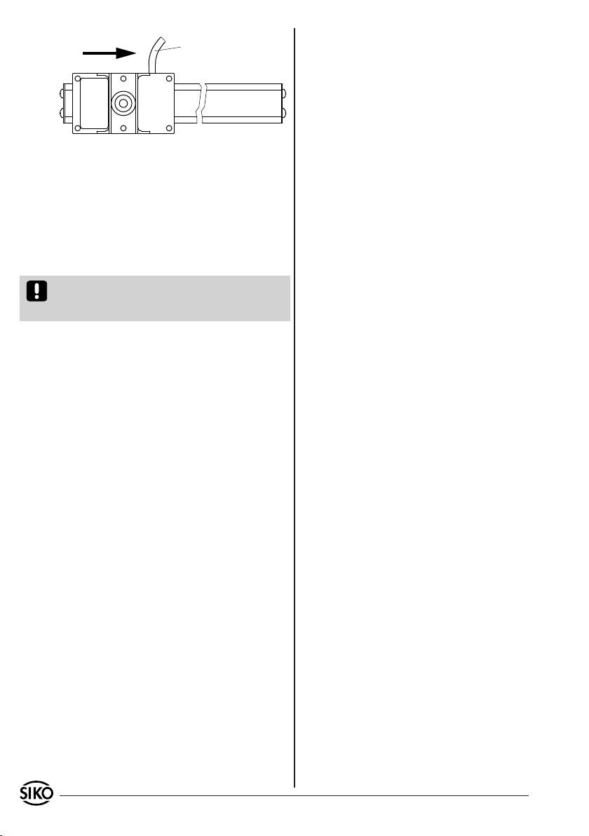
Verfahrrichtung
beim Abgleich
Kabelabgang
Abb. 8: LSA200
Betriebsarten
Es gibt zwei Betriebsarten, in denen das Gerät
mittels der Tastatur beeinflusst werden kann:
Programmiermodus: Einmalige Einrichtung der
1.
Anzeige auf die Anwendung.
Eingabemodus: Funktionen, die während der
2.
normalen Anwendung benötigt werden.
Tastenfuktion / Programmiermodus / Parameterbeschreibung / Eingabemodus etc., siehe
Beiblatt Softwarebeschreibung.
4 MA505 Datum 25.09.2008 Art.Nr. 80475 Änd. Stand 369/08
Page 5
User Information
MA505
Electronic Display absolute
ENGLISH
water, dust, knocks, extreme temperatures.
Attention! Systeminformation! Only when combined with sensor MSA! Before mounting sen-
sor and/or magnetic tape, please read chapter 6
(sensor alignment) and ensure that: the necessary
alignment length is available; that sensor and magnetic tape are aligned correctly.
Built-in housing EG
Push the device into the panel (1) until the panel
•
clips (2) hold the housing loosely.
Press the lateral centering (3) slightly down and
•
push the housing into the cut-out (1) until the
panel clips (2) snap completely.
1. Warranty information
In order to carry out installation correctly, we
•
strongly recommend this document is read very
carefully. This will ensure your own safety and
the operating reliability of the device.
Your device has been quality controlled, tested
•
and is ready for use. Please respect all warnings
and information which are marked either directly
on the device or specified in this document.
Warranty can only be claimed for components
•
supplied by SIKO GmbH. If the system is used
together with other products, there is no warranty
for the complete system.
Repairs should be carried out only at our works.
•
If any information is missing or unclear, please
contact the SIKO sales staff.
2. Identification
Please check particular type of unit and type number from the identification plate. Type number and
the corresponding versionare indicated in the delivery documentation.
eg. MA505-0023
version number
type of unit
3. Installation
For mounting, the degree of protection specified
must be observed. If necessary,protect the unit
against environmental influences such as sprayed
MA505 Datum 25.09.2008 Art.Nr. 80475 Änd. Stand 369/08 5
Fig. 1: Installation
Bench housing TG, TG/DV
The rubber feet can be removed in order to screw
down the unit.
Attention! Maximum screw insert depth of 6,5mm
must be strictly adhered to!
4. Electrical connection
Switch power off before any plug is inserted
•
or removed!
Wiring must only be carried out with power off!
•
Provide standed wires with ferrules.
•
Check all lines and connections before switching
•
on the equipment.
Interference and distortion
All connections are protected against the effects
of interference. The location should be selected
to ensure that no capacitive or inductive interferences can affect the display or the connection lines! Suitable wiring layout and choice
of cable can minimise the effects of interference
(eg. interference caused by SMPS, motors, cyclic
controls and contactors).
Necessary measures
Only screened cable should be used. Wire cross sec-
•
tion is to be at least 0,14mm², max. 0,5mm².
Wiring to screen and to ground (0V) must be via
•
Page 6
a good earth point having a large surface area
for minimum impedance.
The unit should be positioned well away from
•
cables with interference; if necessary a protective
screen or metal housing must be provided. The
running of wiring parallel to the mains supply
should be avoided.
Contactor coils must be linked with spark sup-
•
pression.
PE-connection with 2,5 – 4mm² via PE-clamp (fig. 2).
•
Power supply
is made via mains connection on rear of the device. The correct supply voltage is indicated in
the delivery documentation:
eg.: 230 VAC ±10%
Sensor connection
via 8-poles rear side Mini-Din socket (fig. 2/fig. 6).
Attention! No modifiction of the sensor connection, eg. by cable extension, is permitted.
4.1 Connection, Panel Mounting EG
Sensor PE tag for connection
4.1.1 Optional serial RS232 or RS485 interface
The RS232 or RS485 serial interfaces are connected via terminals 3 (GND), 6 (TXD/ DÜA) and 5
(RXD/ DÜB).
Allocation
terminal EG
Allocation
of TG plug
Fig. 3: Connection diagram RS232 interface option
Allocation
terminal EG
Allocation
of TG plug
Fig. 4: Connection diagram RS485 interface option
4.1.2 Switching output option
Two open collector outputs A1 (terminal 6) and
A2 (terminal 5) are available. The common negative pole of these outputs should be connected to
terminal 3. The admissible voltage range is 30VDC,
the admissible maximum current 10mA per output. The switching behaviour of these outputs is
programmable.
Position value > upper limiting value (UPL): actuator 1 active
•
Position value < lower limiting value (LOL): actuator 2 active
•
Fig. 2: Pin outs EG
No. Description
1 CAL
Allocation
terminal EG
Fig. 5: Connection diagram switching outputs
4.2 Conn., Bench Top Casing TG, TG/DV
Interface/switched outputs
Allocation
of TG plug
2 UB = +12V (for calibration input)
3 GND
4 N.C.
5 RS232 (RXD), RS485 (DÜB), A2
6 RS232 (TXD), RS485 (DÜA), A1
7 PE
8 N (230/115 VAC), GND (24 VDC)
9 L (230/115 VAC), UB (24 VDC)
6 MA505 Datum 25.09.2008 Art.Nr. 80475 Änd. Stand 369/08
Sensor Calibration input Power 230VAC, 115 VAC
Page 7
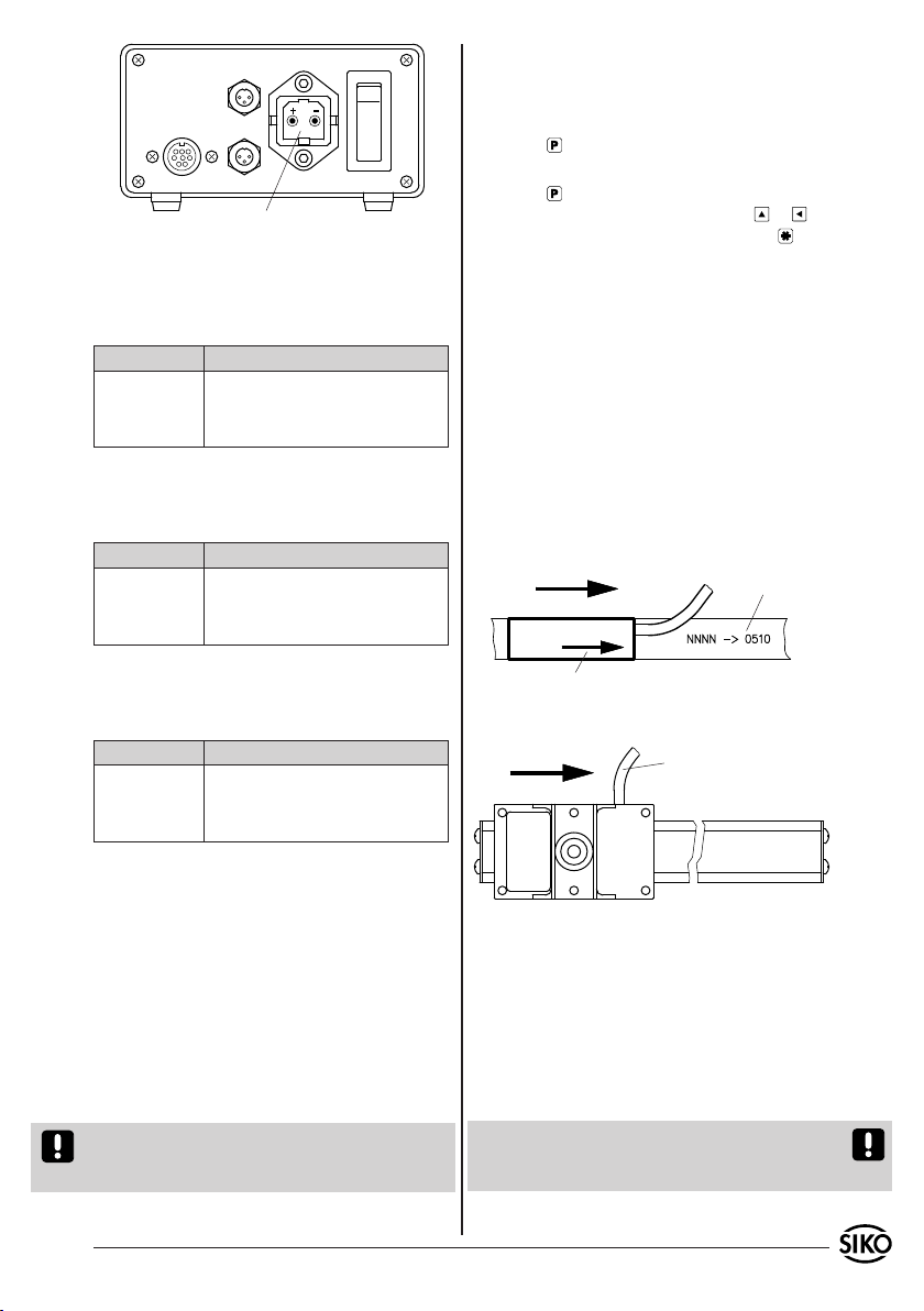
Power 24 VDC
Fig. 6: Rear panel connections TG, TG/DV
Option: Calibration input
via a socket at the rear; pin connections are to be
made as follows (fig. 6):
No. Description
1 CAL
2 GND
3 UB
Option: serial interface
via a socket at the rear; pin connections are to be
made as follows (fig. 6):
No. Description
1 GND
2 RXD / DÜB
3 TXD / DÜA
5.1 MSA, LSA200 Sensor Alignment
When mounting the system, please ensure that the
arrows marked on sensor and magnetic strip head
in the same direction (see Fig. 7).
Press key for at least 5s (pre-programmed) to
enter into programming mode.
Press key briefly and repeately to reach menu
point "CODE". Use the two arrow keys + to
enter value "00100" and confirm with key . You
are now in automatic alignment mode, which ist
signalled by the alternating display of "ink", "Versatz" (only LSA200) or "abs" and the corresponding alignment values.
Now sensor must be moved at a speed of max.
1mm/s (LSA200) or max. 10mm/s (MSA) in the
direction of the cable outlet. Sensor alignment
will be completed after approx. 20mm. The
actual position value is now displayed. Now go
on with parameter programming in programming
menu and zero/calibrate the MA505. (The manual
is supplied with an appendix called ‘software description’ which also gives information on the programmable parameters.)
Travel direction during alignment Printing on
the strip
Option: switched outputs
via a socket at the rear; pin connections are to be
made as follows (fig. 6):
No. Description
1 GND
Printing on the botton of the sensor (active side)
Fig. 7: Sensor MSA
Travel direction
during alignment
Cable outlet
2 A2
3 A1
5. Commissioning
When switched on and correctly connected:
hardware version display (eg. SIKO:MA505) for
•
approx. 1,5 s
firmware version display (eg. V1.00)
•
sensor type is displayed (eg. MSA)
•
display of address (eg. address: 31) only with
•
Interface protocol SIKONETZ 3
Subsequently the specific parameters of the machine can be programmed.
Before the first use of the system or after replacement of one of its components (display, sensor or
magnetic strip) the sensor must be calibrated.
MA505 Datum 25.09.2008 Art.Nr. 80475 Änd. Stand 369/08 7
Fig. 8: LSA200
Operating mdes
There are two operating modes accessible via the
keyboard:
Programming mode: to program the display at
1.
initial installation.
Input mode: to enter parameters/select func-
2.
tions used during standard operation.
Key's function / Programming mode / Parameter description / Input mode etc., see enclosed
page with software description.
Page 8
SIKO GmbH
Werk / Factory:
Weihermattenweg 2
79256 Buchenbach-Unteribental
Postanschrift / Postal address:
Postfach 1106
79195 Kirchzarten
Telefon/Phone +49 7661 394-0
Telefax/Fax +49 7661 394-388
E-Mail [email protected]
Internet www.siko.de
Service [email protected]
8 MA505 Datum 25.09.2008 Art.Nr. 80475 Änd. Stand 369/08
 Loading...