

Page 1
IF09P Datum 07.11.2001 Art.Nr. 79121 Z.Nr. 8666013 Änd.Stand 374/01 1
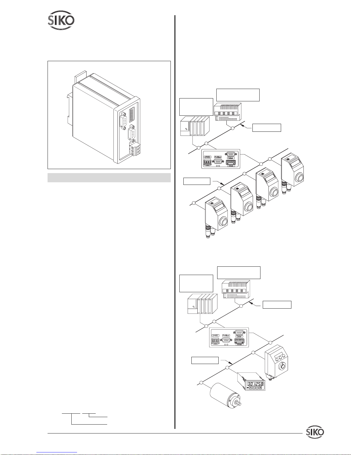
3. Systemaufbau
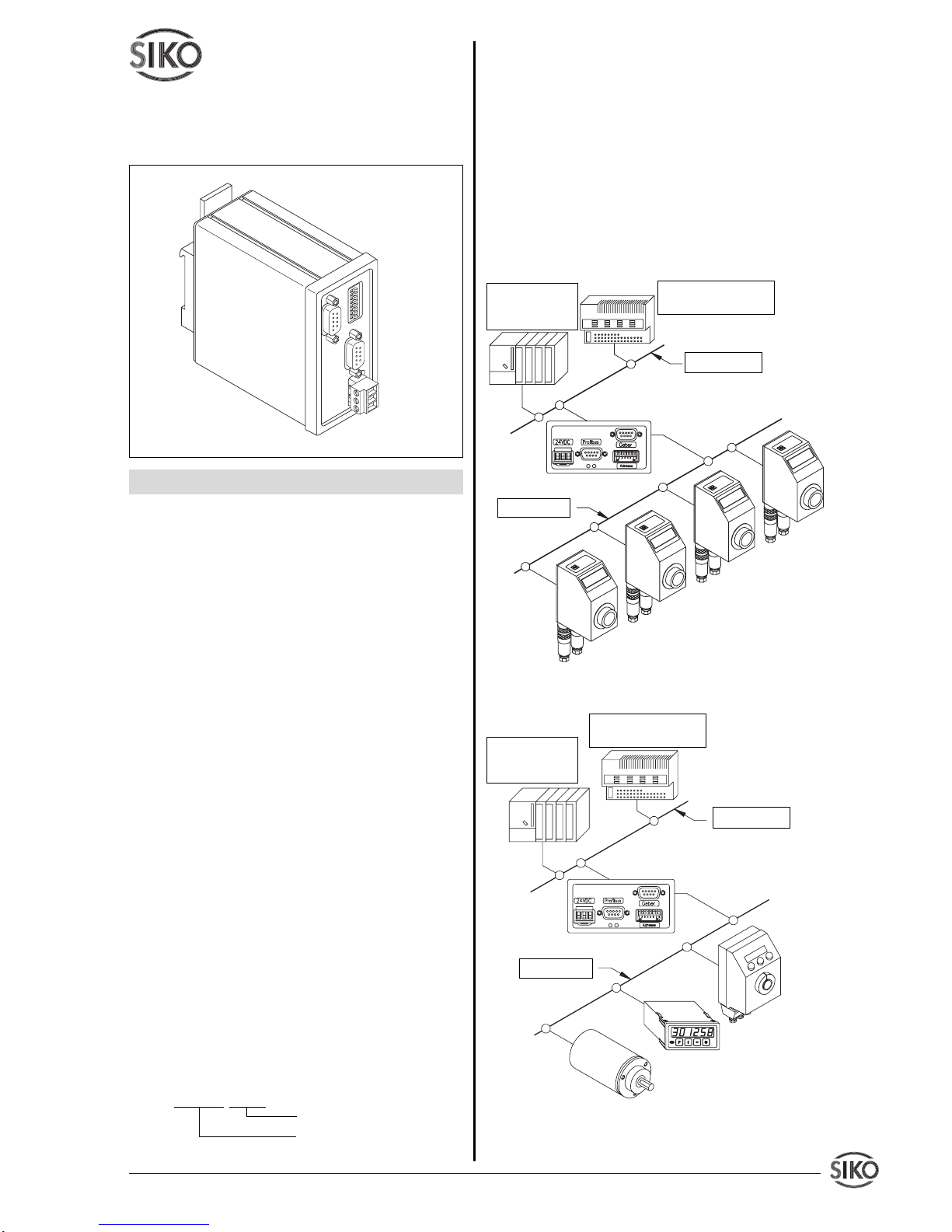
Die Aufgabe des Profibus-Gateway IF09P besteht hauptsächlich darin, SIKO-Positionswertgeber vom Typ AP09 an den PROFIBUS-DP
anzukoppeln. Wahlweise besteht die Möglichkeit, Geräten mit SIKONETZ3-Schnittstelle den
Anschluss an PROFIBUS-DP zu ermöglichen.
Ein gemeinsamer Anschluss von AP09 und
SIKONETZ3-Geräten ist nicht möglich. Die Auswahl der beiden Schnittstellenprotokolle erfolgt
über einen DIP-Schalter am IF09P.
Abb. 1 : Systemaufbau (IF09P mit AP09)
Abb. 2 : Systemaufbau (IF09P mit SIKONETZGeräten)
Benutzerinformation
IF09P
Interface Profibus
DEUTSCH
1. Gewährleistungshinweise
• Lesen Sie vor der Montage und der Inbetriebnahme dieses Dokument sorgfältig durch. Beachten Sie zu Ihrer eigenen Sicherheit und der
Betriebssicherheit alle Warnungen und Hinweise.
• Ihr Produkt hat unser Werk in geprüftem und
betriebsbereitem Zustand verlassen. Für den
Betrieb gelten die angegeben Spezifikationen
und die Angaben auf dem Typenschild als Bedingung.
• Garantieansprüche gelten nur für Produkte
der Firma SIKO GmbH. Bei dem Einsatz in
Verbindung mit Fremdprodukten besteht für das
Gesamtsystem kein Garantieanspruch.
• Die Garantiezeit beträgt 6 Monate ab Rechnungsdatum
• Reparaturen dürfen nur im Werk vorgenommen werden. Für weitere Fragen steht Ihnen die
Firma SIKO GmbH gerne zur Verfügung.
2. Identifikation
Das Typenschild zeigt den Gerätetyp mit Variantennummer. Die Lieferpapiere ordnen jeder
Variantennummer eine detaillierte Bestellbezeichnung zu.
z.B. IF09P-0023
Varianten-Nr.
Geräte-Typ
Profibus-DP
PROFIBUS-Slave,
z.B.: ET200B
Master-SPS,
z.B.:SIEMENS
S7-315
IF09P
SIKONETZ3
WK58
MA10/3
AP03/1
IF09P
AP09
AP09
AP09
AP09
RS485-Bus
Profibus-DP
PROFIBUS-Slave,
z.B.: ET200B
Master-SPS,
z.B.:SIEMENS
S7-315
Page 2
2 IF09P Datum 07.11.2001 Art.Nr. 79121 Z.Nr. 8666013 Änd.Stand 374/01
4. Mechanische Montage
Die Montage darf nur gemäß der angegebenen
IP-Schutzart vorgenommen werden. Das System muss ggfs. zusätzlich gegen schädliche
Umwelteinflüsse, wie z.B. Spritzwasser, Staub,
Schläge, Temperatur geschützt werden.
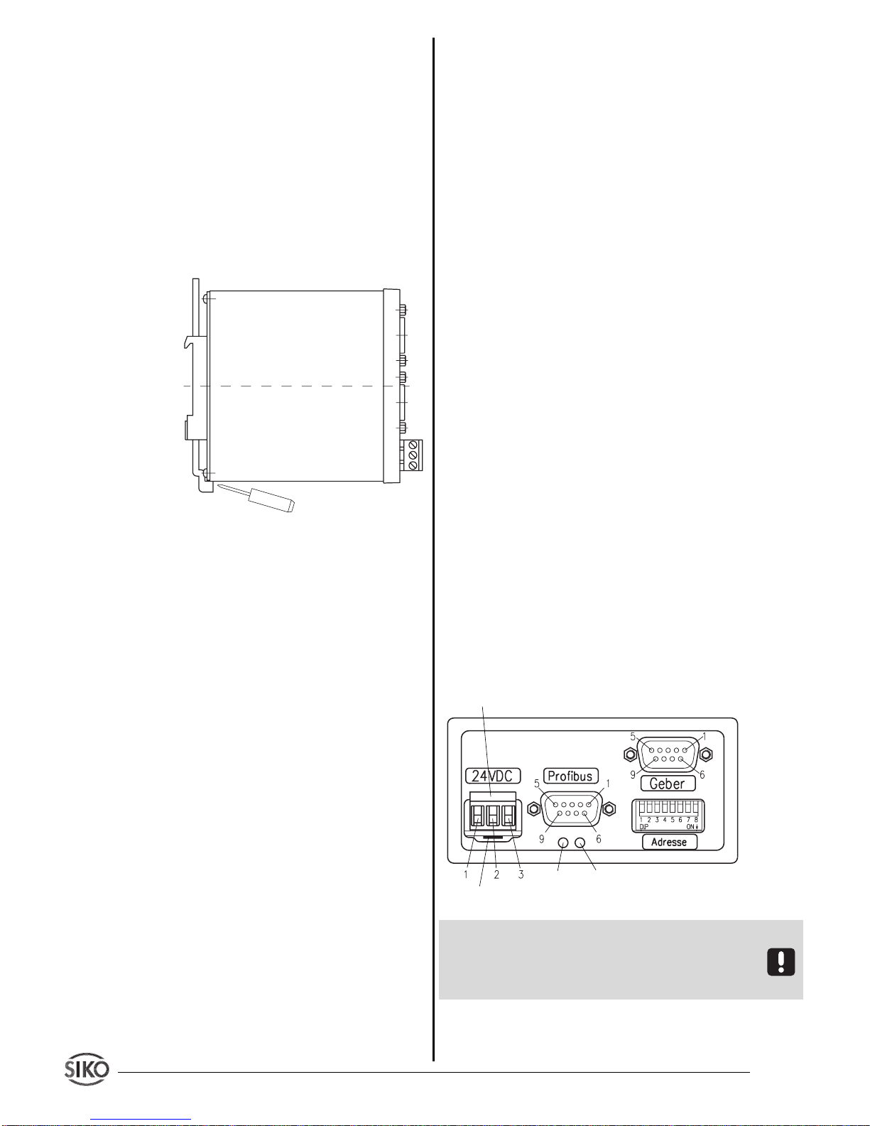
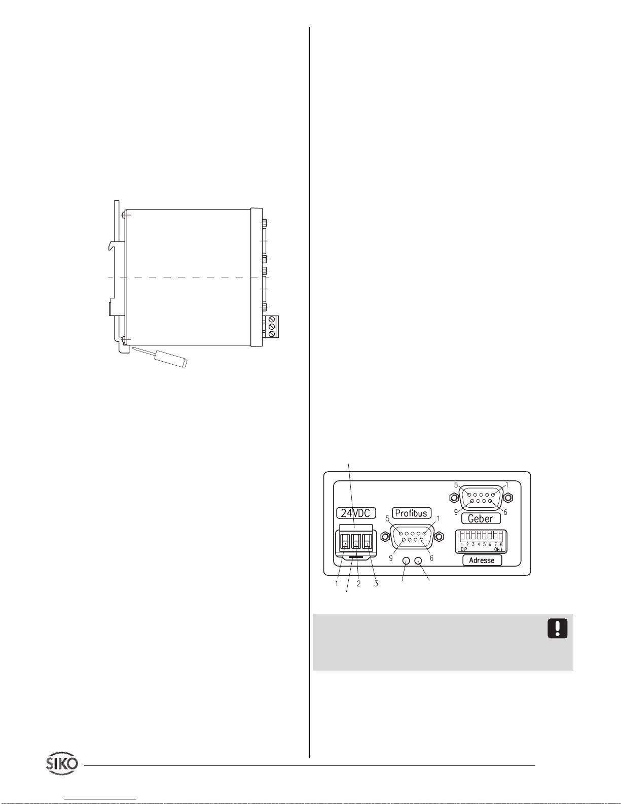
Das IF09P ist zum Anbau an eine Hutschiene
35x7.5 nach DIN 50022 vorgesehen. Zur Montage ist der Halter auf die Hutschiene aufzuschnapppen und darauf zu achten, dass sich die
Verriegelung unten befindet. Zur Demontage
wird der Riegel nach unten geschoben.
Abb. 3 : Einbau
5. Elektrischer Anschluss
• Bei Verwendung in Antriebssystemen sind
zusätzliche Sicherheitsabschaltungen z.B. durch
Endlagenschalter oder andere Verriegelungen
vorzusehen.
• Verdrahtungsarbeiten dürfen nur spannungslos erfolgen!
• Litzen sind mit Aderendhülsen zu versehen.
• Vor dem Einschalten sind alle Leitungsanschlüsse und Steckverbindungen zu überprüfen.
Hinweise zur Störsicherheit
Alle Anschlüsse sind gegen äußere Störeinflüsse geschützt. Der Einsatzort ist aber so zu
wählen, dass induktive oder kapazitive Störungen nicht auf das Gerät oder dessen Anschlussleitungen einwirken können! Durch
geeignete Kabelführung und Verdrahtung können Störeinflüsse (z.B. von Schaltnetzteilen,
Motoren, getakteten Reglern oder Schützen)
vermindert werden.
Erforderliche Maßnahmen:
• Nur geschirmtes Kabel verwenden. Den Kabelschirm beidseitig auflegen. Litzenquerschnitt der
Leitungen min. 0,14 mm2, max. 0,5 mm2.
• Die Verdrahtung von Abschirmung und Masse (0 V) muss sternförmig und großflächig erfolgen. Der Anschluss der Abschirmung an den
Potentialausgleich muss großflächig (niederimpedant) erfolgen.
• Das System muss in möglichst großem Abstand von Leitungen eingebaut werden, die mit
Störungen belastet sind; ggfs. sind zusätzliche
Maßnahmen wie Schirmbleche oder metallisierte Gehäuse vorzusehen. Leitungsführun-
gen parallel zu Energieleitungen vermeiden.
• Schützspulen müssen mit Funkenlöschgliedern beschaltet sein.
• PE- Verbindung mit 2.5– 4 mm2 über PE-Anschluss (Flachsteckhülse 6,3x0,8).
• Zur Datenübertragung sind Kabellängen bis
max. 200m möglich.
Technische Daten
• Stromversorgung 24VDC ±20%
• Leistungsaufnahme ca. 1,8W
• DC/DC-Wandler für galvanisch getrennte DPSchnittstelle
• Mikrocontroller 80C528
• Siemens SPC3-Controller
• Datenrate bis 12 Mbit/s.
• 7-Bit-Adresse über DIP-Schalter wählbar. (Profibus-Teilnehmeradresse)
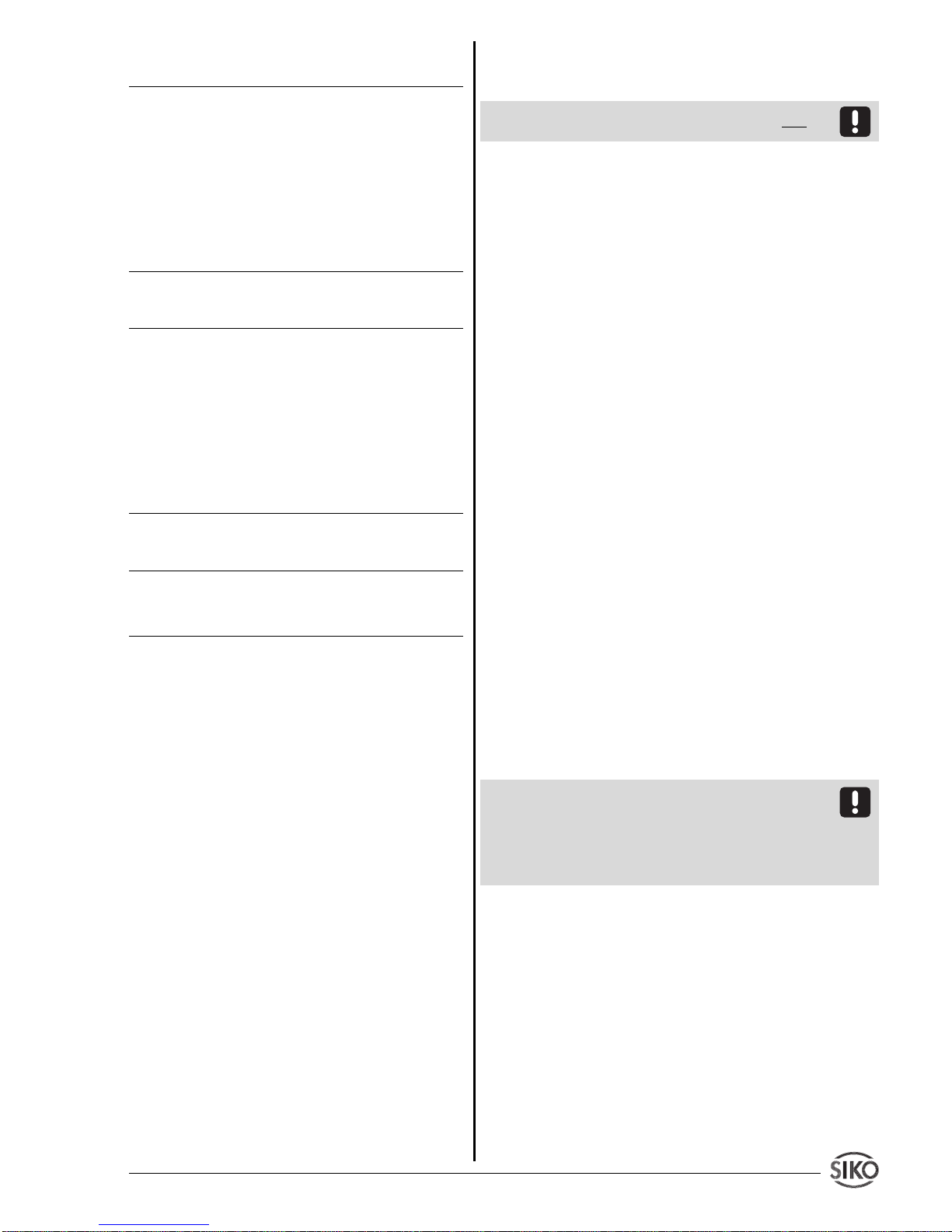
Anschluss Stromversorgung
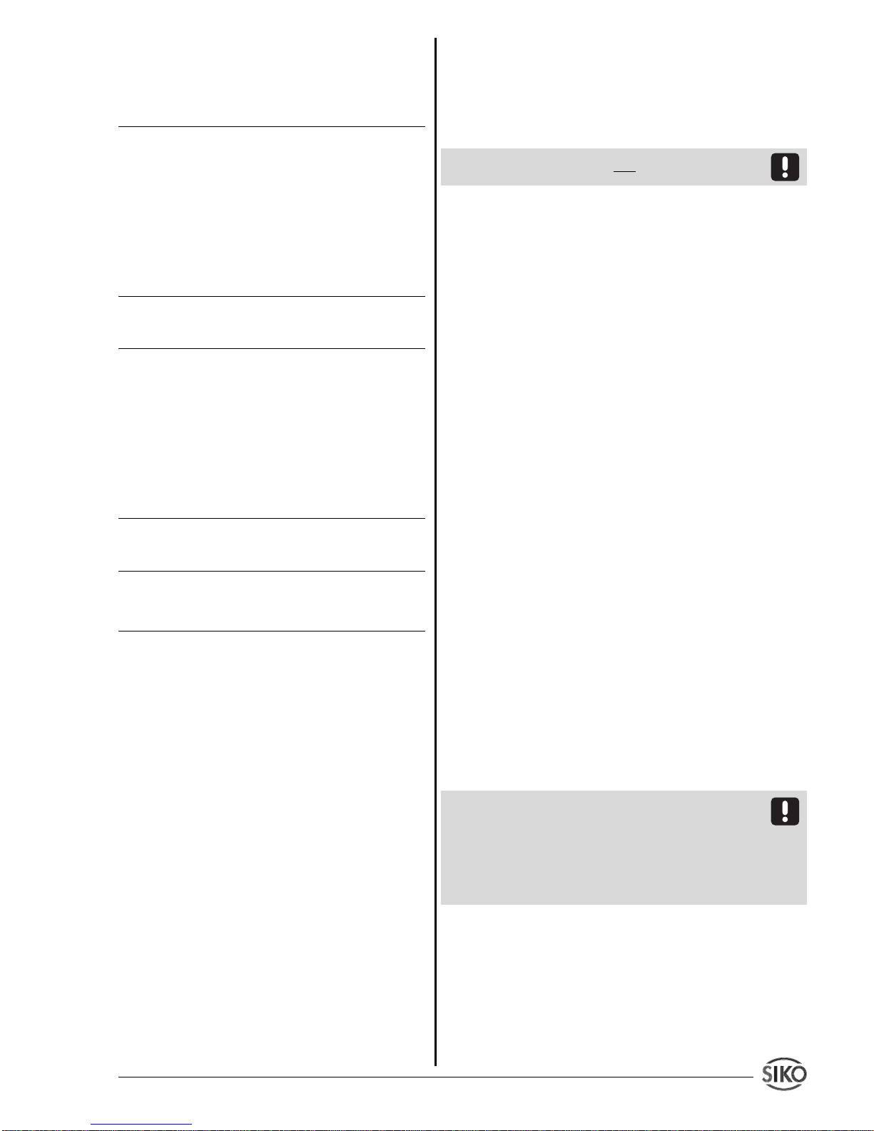
Der Anschluss erfolgt über die 3-pol. Klemmleiste an der Gerätevorderseite.
ACHTUNG: Aus EMV-technischen Gründen ist es
erforderlich, über den 6,3mm-Flachsteckeranschluss
eine niederimpedante Verbindung zum Potentialausgleichsystem herzustellen!
LED Power Good: zeigt an, dass die interne
Versorgungsspannung im tolerierbaren Bereich
liegt.
Stromversorgung
PE-Anschluss
Power
Good
DE
Page 3
IF09P Datum 07.11.2001 Art.Nr. 79121 Z.Nr. 8666013 Änd.Stand 374/01 3
LED DE: zeigt den Zustand "Data Exchange"
auf dem Profibus an.
Anschluss Geber
Pin Belegung
1 +UB 24VDC
2 N.C.
3 DÜA
4 N.C.
5 GND
6 N.C.
7 N.C.
8 DÜB
9 N.C.
Anschluss Profibus
Pin Belegung
1 N.C.
2 N.C.
3 B-Line
4 RTS
52M
6 2P5
7 N.C.
8 A-Line
9 N.C.
Stromversorgung
Pin Belegung
1PE
20V
3 +24VDC ± 20%
6. Eigenschaften
6.1 Profibus-Schnittstelle
Die Verbindung des IF09P zum Profibus erfolgt
über einen 9-poligen DSUB-Steckverbinder gemäß EN 50170. Eine eventuell vorzunehmende
Busterminierung muss im Anschlussstecker vorgenommen werden, d.h. es sind entsprechende
Steckverbinder mit zuschaltbaren Abschlusswiderständen einzusetzen. Es werden folgende
Datenraten unterstützt: 9,6kBit/s, 19,2kBit/s,
93,75kBit/s, 187,5kBit/s, 500kBit/s, 1,5MBit/s,
3MBit/s, 6MBit/s und 12Mbit/s. Weitere Profibusspezifische Parameter enthält die zugehörige Gerätestammdatei SIKO00EC.GSD,
die auf Anforderung erhältich ist bzw. unter
http://www.siko.de/download
6.2 Schnittstelle zu AP09 bzw. SIKONETZ3
(Anschluss "Geber")
Die Schnittstelle zu den Gebern (AP09 bzw.
SIKONETZ3-Geräten) ist Hardwaremäßig auf
einem 9-poligen DSUB-Steckverbinder aufgebaut und basiert auf der RS485-Norm. Die Baudrate beträgt bei dem AP09-Protokoll 115,2kBit/
s, beim SIKONETZ3-Protokoll 19,2kBit/s. Über
zwei zusätzliche Pin’s kann die Versorgung der
angeschlossenen Geber vorgenommen werden.
Der Anschlussstrom darf 1A nicht übersteigen!
6.3 Funktionsweise
In der Datenaustauschphase fragt das IF09P die
angeschlossenen Geber auf deren Positionswerte ab. Diese werden über den Profibus-Protokollchip SPC3 der Masterstation (z.B. Siemens
S7) zur Verfügung gestellt.
Des weiteren besteht die Möglichkeit, die angeschlossenen Geber von der Master-SPS aus
über bestimmte Befehle zu parametrieren, Statusabfragen durchzuführen oder Systemkommandos ausführen zu lassen. Die Beschreibung
der Datentelegramme sowie der Befehlstabelle
ist weiter unten aufgeführt.
Fehlerzustände, wie falsche Parameter, falsche
Teilnehmeradressen oder Kommunikationsfehler werden vom IF09P erkannt und der MasterSPS durch Fehlercodes im Datentelegramm
mitgeteilt.
6.3.1 Startphase
Unter der Voraussetzung, dass sämtliche Geräte, IF09P und die Geber (AP09 bzw. SIKONETZ3-Teilnehmer) gemeinsam eingeschaltet
werden, läuft folgende Einschaltsequenz ab:
• Die SIKONETZ-Teilnehmer initialisieren sich.
• Das IF09P initialisiert sich ebenfalls und wartet ca. 2,5s bis sich die Geber initialisiert haben.
• Das IF09P stellt nun die angeschlossene
Anzahl an Gebern fest.
WICHTIG:
Die Geber müssen in aufsteigender
Adressreihenfolge, beginnend mit Adresse 1,
eingestellt werden! Es dürfen keine "Adresslükken" auftreten! Zur Adresseinstellung an den
Gebern ist die jeweilige Benutzerinformation zu
Rate zu ziehen.
6.3.2 Betriebsphase
• Nach feststellen der Anzahl angeschlossener
Geber wird die PROFIBUS-Schnittstelle initialisiert und daran anschließend begonnen, in einer
Programmschleife, die Positionswerte der Geber abzufragen und der Profibus-Schnittstelle
zur Verfügung zu stellen.
Page 4
4 IF09P Datum 07.11.2001 Art.Nr. 79121 Z.Nr. 8666013 Änd.Stand 374/01
6.3.3 Parametrierphase
• Sendet die Master-SPS eine Parametrieranforderung an das IF09P, wird die Positionswertabfrage solange unterdrückt, bis die Parameteranforderung bearbeitet wurde. Die Abarbeitung
der Anforderung wird der Master-SPS duch einen Bestätigungscode mitgeteilt.
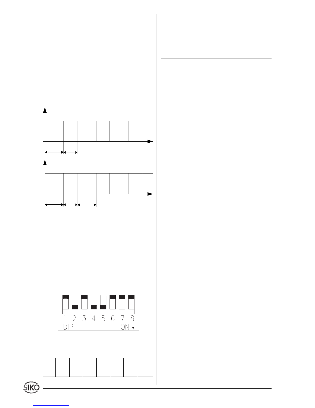
6.4 Zykluszeiten
Der zeitliche Ablauf der Positionswertabfrage
und der Profibus-Schnittstellenbedienung ist im
unten abgebildeten Diagramm dargestellt (AP09Protokoll !):
Die mit X angegebenen Zeiten verlängern sich
bei SIKONETZ3-Betrieb entsprechend der geringeren Baudrate !
7. Bedienung
7.1 Adresseinstellung (Profibus-SlaveAdresse)
Mit den DIP-Schaltern SW1/1..SW1/7 wird die
Profibus-Slave-Adresse des IF09P eingestellt.
Zulässig sind die Slave-Adressen 0..125.
Abb. 4 : Adressschalter
Wertigkeit
1 2 4 8 1 6 3 2 6 4 Proto-
kolltyp
SW1/1 SW1/2 SW1/3SW1/4 SW1/5 SW1/6 SW1/7 SW1/8
Positionswertabfrage
Adr. n
Profibus
Positionswertabfrage
Adr. n+1
Profibus
Positionswertabfrage
Adr. n+2
Profibus
ca.3,8msXca.2ms
Positionswertabfrage
Adr. n
Profibus
Parametrierung
bearbeiten
Profibus
Positionswertabfrage
Adr. n+1
Profibus
ca.3,8msXca.2ms
ca.3..20ms
X
Beispiel zur Adresseinstellung:
Gewünschte Adresse = 26
Dez
(= 1A
Hex
)
SW1/5 = ON (Wertigkeit 16)
+ SW1/4 = ON (Wertigkeit 8)
+ SW1/2 = ON (Wertigkeit 2)
Adresse 16+8+2 = 26
Dez
Die übrigen Schalter (SW1/1, SW1/3, SW1/6
und SW1/7) bleiben in diesem Fall in Stellung
OFF.
7.2 Umschaltung des Protokolls der GeberSchnittstelle
An der RS485-Schnittstelle können wahlweise
Geber mit AP09- oder SIKONETZ3-Protokoll
angeschlossen werden. Mit dem Schalter SW1/
8 wird das gewünschte Protokoll eingestellt:
SW1/8 = OFF: AP09-Protokoll
SW1/8 = ON: SIKONETZ3-Protokoll
Eine Veränderung dieser DIP-Schalterstellung
während des laufenden Betriebs wird nicht erkannt. Die Erkennung des Schalterzustands
erfogt ausschließlich während des Einschaltens!
7.3 Abschluss der PROFIBUS-DP-Leitung
Am ersten und letzten Busteilnehmer muss die
Leitung mit 3 Widerständen abgeschlossen werden, diese sind wie folgt anzuschließen:
390 Ohm zwischen PIN6 (2P5) und PIN3 (BLine)
390 Ohm zwischen PIN8 (A-Line) und PIN5 (2M)
220 Ohm zwischen PIN3 (B-Line) und PIN8 (A-
Line)
Werden Anschlussstecker mit eingebautem
Leitungsabschluss verwendet, so ist dieser am
ersten und am letzten Busteilnehmer einzuschalten.
7.4 Konfiguration/Projektierung
Für das PROFIBUS-DP-Gateway wurde eine
Gerätestammdatendatei mit dem Namen
SIKO00EC.GSD erstellt. Diese Datei kann mit
dem verwendeten Projektierungstool z.B. COM
PROFIBUS (ab V3.3) für die PROFIBUS-DP
PC-Karte CP5412A2 der Firma Siemens oder
dem entsprechende Projektierungstool für SPS
(z.B. S7) in die Geräte-Bibliothek aufgenommen
werden (die Vorgehensweise hierfür sind den
Page 5
IF09P Datum 07.11.2001 Art.Nr. 79121 Z.Nr. 8666013 Änd.Stand 374/01 5
Unterlagen des Projektierungstools zu entnehmen).
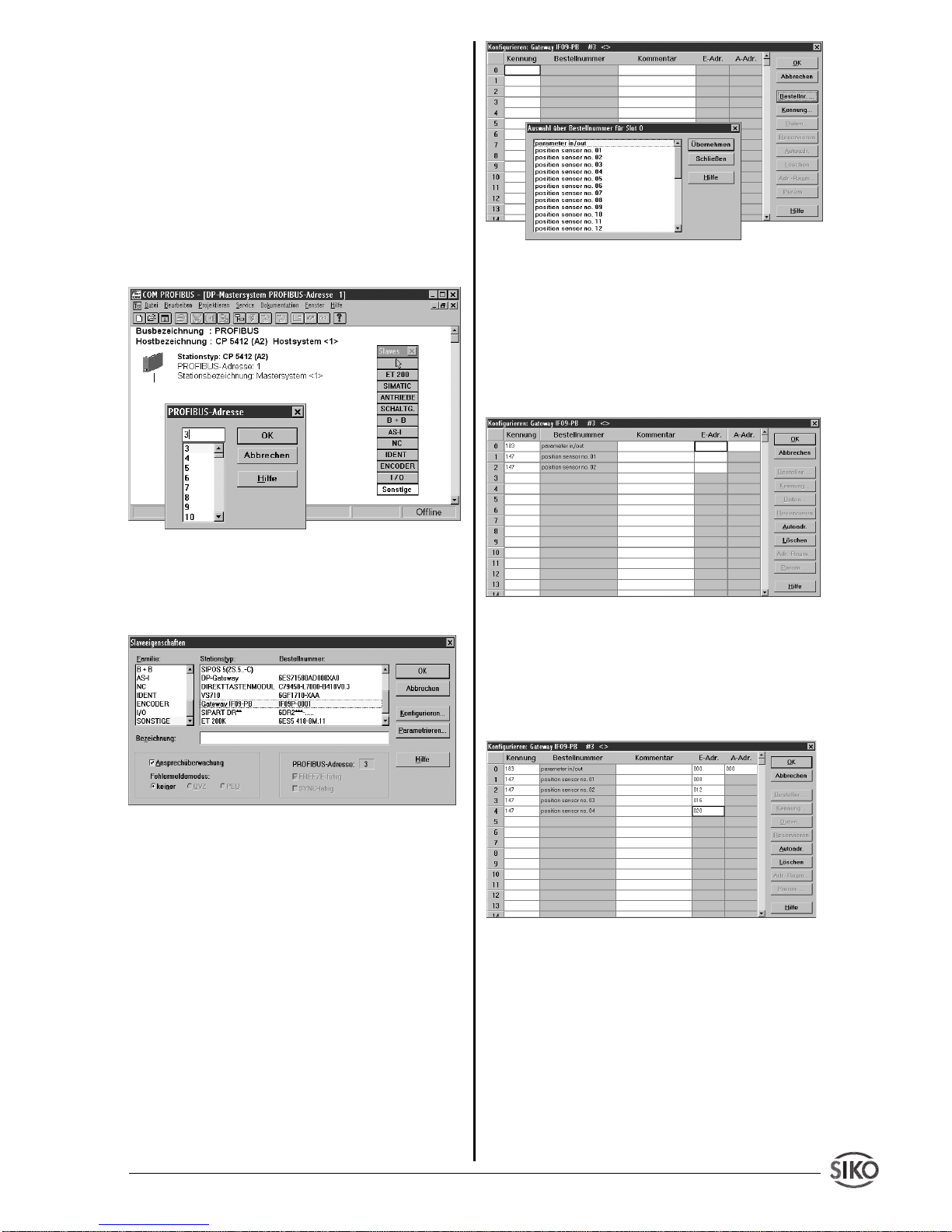
An Hand einer Beispielprojektierung soll die
Vorgehensweise beim einbinden des IF09P in
einer Profibusanlage dargestellt werden. Als
Projektierungstool wird das Programm
COM-
PROFIBUS
verwendet. Folgende Bedingungen
werden vorausgesetzt:
1.) Die Gerätestammdatei (
SIKO00EC.GSD
) be-
findet sich im richtigen Verzeichnis und
2.) mind. 1 Masterbaugruppe wurde ausgewählt.
1. Schritt: Auswahl des einzufügenden Profibusteilnehmers (hier: Gateway IF09P). Dieser
befindet sich unter der Rubrik "Sonstige".
Nach Anwahl dieses Punktes wird nach der
gewünschten Teilnehmeradresse gefragt. Die
gewählte Adresse muss mit der am IF09P eingestellten Adresse übereinstimmen!
2. Schritt: Gateway IF09P aus der angebotenen
Liste auswählen. Durch anklicken von "Konfigurieren..." wird das Gateway an den geplanten
Aufbau angepaßt.
3. Schritt: Konfiguration des Gateways's. Das
IF09P ist ein modularer Slave, bei dem bei der
Projektierung als 1. Modul immer das Modul
"Parameter In/Out"
eingetragen werden muss.
Durch anklicken des Menüpunktes "Bestellnr..."
wird ein weiteres Fenster geöffnet, aus dem die
einzutragenden Module ersichtlich sind.
Über das Modul
"Parameter In/Out"
erfolgt die
Parametrierung der angeschlossenen Geber sowie des Gateway selbst.
Mit
"Übernehmen"
wird das gewählte Modul in
die Kennungsliste aufgenommen. Im Anschluss
daran werden die Module
"position sensor no.
xx"
an die weiteren Positionen übernommen.
Im Feld
"E-Adr."
und
"A-Adr."
muss nun eine
Adresse im Bereich 000...240 eingegeben werden, wo die Daten abgelegt werden. Im einfachen Fall kann per Menüpunkt
"Autoadr."
diese Adressvergabe automatisch durchgeführt werden.
Dabei ist zu beachten, dass die Geber-Adressen
immer in aufsteigender Reihenfolge einzutragen
sind. In dieser Reihenfolge werden die Geber
auch von dem Gateway abgefragt und die Positionswerte in das Datentelegramm eingetragen.
Mit
"OK"
wird das Konfigurationsmenü beendet,
das IF09P ist als Profibusteilnehmer eingetragen und konfiguriert.
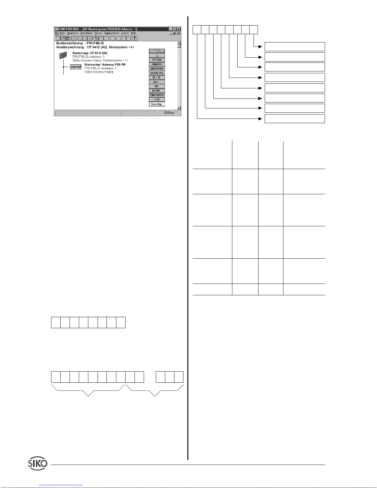
Alle weiteren Einstellungen erfolgen automatisch
über die Gerätestammdatendatei, z.B. ob der
Profibusteilnehmer die globalen Kommandos
Page 6
6 IF09P Datum 07.11.2001 Art.Nr. 79121 Z.Nr. 8666013 Änd.Stand 374/01
"Freeze"
bzw.
"Sync"
unterstützt.
7.5 Telegrammaufbau im Zustand DATAEXCHANGE
Beim PROFIBUS-DP ist die Parametrierung
eines Slaves während der DATA-EXCHANGEPhase nur sehr eingeschränkt möglich. Außerdem sind Parameter beim PROFIBUS-DP grundsätzlich nicht lesbar.
Überlicherweise wird die Parametrierung eines
Slaves nur einmalig in der Anlaufphase durchgeführt. Diese Parameter müssen während der
Projektierung mit einem geeigneten Softwaretool festgelegt werden (siehe Absatz 7.3).
Während des Betriebs werden dann nur noch
Ein- und Ausgabedaten zwischen Master und
Slave ausgetauscht. Um auch dann noch einen
Parameteraustausch zu ermöglichen, werden
die ersten 8 Datenbytes ("parameter in/out") im
Sende- und Empfangstelegramm zur Parameterübergabe genutzt.
Datentelegramm vom Master zum IF09P:
Länge = 8 Byte, enthält Parametrierdaten und
Steuerkommandos
Datentelegramm vom IF09P zum Master:
Länge = 8 Byte Status-/Parametrierdaten +
Anzahl_Geber * 4 Byte (= max. 31*4+8Byte =
132Byte
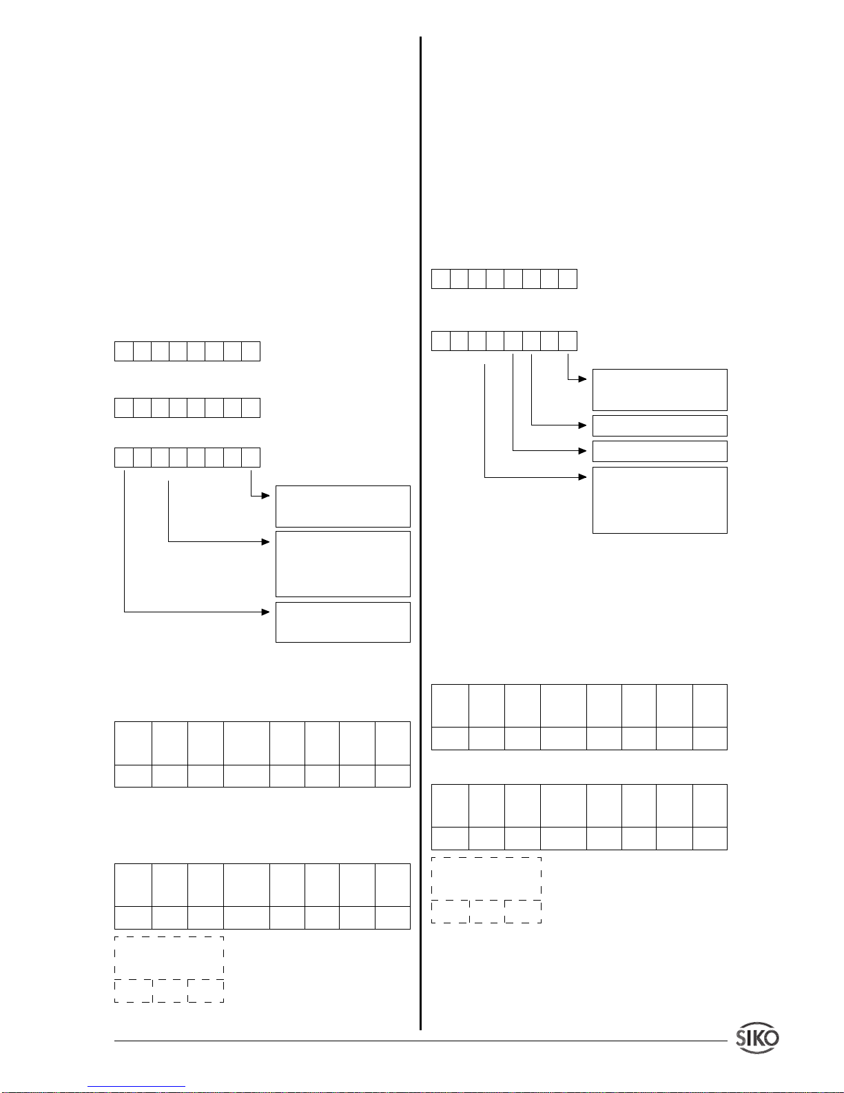
Aufbau der ersten 8 Bytes des Datentelegramms
(gilt für Datenrichtung Master -> IF09P als auch
IF09P -> Master)
12345678
12345678
...
Status-/Steuerdaten Nutzdaten
Byte Nr.
Byte 1 : Befehlscode
Befehl Befehls- Befehls- Bedeutung
code code
(Dienst) (hexa- (Dezimal)
dezimal)
Write Request 23H 35 Parameter zum
Gateway IF09P
senden
Write Response 60H 96 Antwort des
Gateway IF09P
auf Write Request
Read Request 40H 64 Anforderung
eines Parameters vom Gateway IF09P
Read Response 42H 66 Antwort auf An-
forderung mit
aktuellem Wert
Error Response 80H 128 Fehlermeldung
Der Befehlscode ist während dem regulärem
Data-Exchange-Betrieb auf 00H gesetzt.
Byte 2,3: Parameterindex
Der Parameterindex wird im Intel-Datenformat
im Nutzdatenbyte 2 (Low Byte) und im Nutzdatenbyte 3 (High Byte) eingetragen (Beschreibung siehe
Punkt 7.6 Befehlsliste
)
Byte 4: Subindex
Der Parameter
Subindex
stellt die Adresse des
über das IF09P anzusprechende AP09 bzw.
SIKONETZ-Teilnehmers dar. Der Wertebereich
ist 0..31. (0 = Gateway IF09P, 1..31 = angeschlossene Geber).
Die folgende Aussage gilt nur für bei eingestelltem SIKONETZ3-Protokoll:
Über das Bit an der Stelle
Bit 6 (Rundruf)
kann
gesteuert werden, ob der Befehl für alle Teilneh-
12345678
Datenbyte 2
Datenbyte 3
Datenbyte 4 (High Byte)
Datenbyte 1 (Low Byte)
Parameterindex (Low Byte)
Parameterindex (High Byte)
Subindex (= Adresse)
Befehlscode
Page 7
IF09P Datum 07.11.2001 Art.Nr. 79121 Z.Nr. 8666013 Änd.Stand 374/01 7
mer gelten soll oder nicht. Bei gesetztem Bit ( =
1) wird die Adresse (des SIKONETZ3-Teilnehmers) ignoriert, ansonsten gilt der Befehl nur für
das Gerät mit der angegebenen Adresse. Wird
als Adresse der Wert 0 angegeben so wird das
Rundrufbit ignoriert. Welche Befehle Rundruffähig sind, geht aus der Befehlsliste hervor (siehe
Absatz 7.6
).
Byte 5..8: Datenbyte1..Datenbyte 4
Im Datenbereich wird der Wert des Parameters
in linksbündiger Intel-Darstellung eingetragen.
(Byte 5 = Low Byte .. Byte 8 = High Byte)
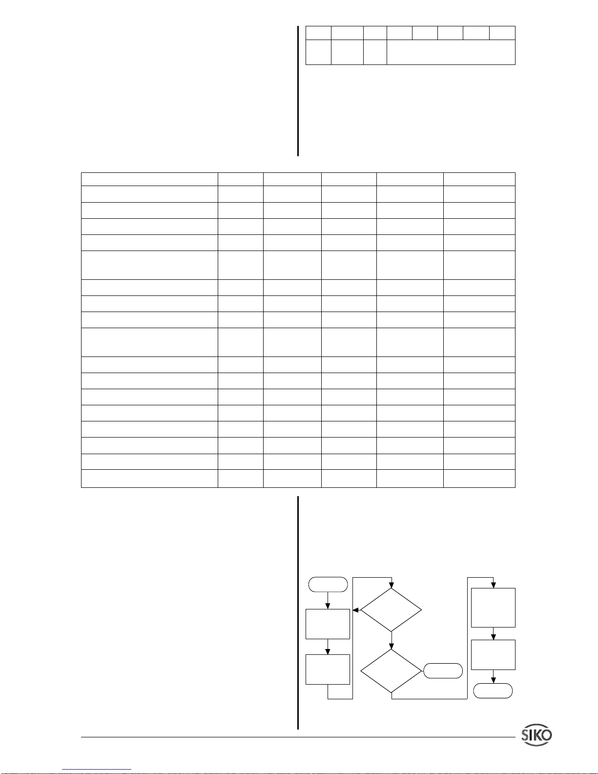
7.6 Befehlsliste (Indextabelle)
Parameter Index Subindex Datentyp Datenlänge Zugriff
Positionswert 5F00H 1..31 Integer32 4 R
Kalibrierwert 5F01H 1..31 Integer32 4 R/W
Offset
5)
5F02H 1..31 Integer32 4 R/W
Gerätekennung IF09-P 5F03H 0 Integer32 4 R
Zählrichtung (SIKONETZ3) 5F04H 1..31 Integer32 4 R/W
Status/Konfiguration (AP09)
Schritte pro Umdrehung 5F05H 1..31 Integer32 4 R/W
Status IF09-P 5F06H 0 Integer32 4 R
Softwarekalibrierung/Reset 5F07H 1..31 Integer32 4 W
1)
System-Status SIKONETZ- 5F08H 1..31 Integer32 4 R/W
1)2)
Geber
Nicht implementiert
3)
5F09H - - - Sollwert 5F0AH 1..31 Integer32 4 W
Tastatur einschalten
1)4)5)
5F0BH 1..31 Integer32 4 W
Tastatur ausschalten
1)4)5)
5F0CH 1..31 Integer32 4 W
Positionieren starten
5)
5F0DH 1..31 Integer32 4 W
Positionieren stoppen
1)4)5)
5F0EH 1..31 Integer32 4 W
Anzeige einschalten
1)4)5)
5F0FH 1..31 Integer32 4 W
Anzeige ausschalten
1)4)5)
5F10H 1..31 Integer32 4 W
1)
Der Inhalt der Nutzdatenbytes ist ohne Bedeu-
tung.
2)
Der Schreibzugriff löscht den System-Status
des adressierten Geber.
3)
Ein Schreib-/Lesezugriff mit diesem Index
erzeugt eine Fehlermeldung
4)
Diese Befehle sind
Rundruf
-fähig.
5)
Diese Parameter sind bei AP09 nicht möglich
und erzeugen eine Fehlermeldung
Zugriff = R: nur Lesezugriff möglich.
Zugriff = W: nur Schreibzugriff möglich.
Zugriff = R/W: Schreib- und Lesezugriff möglich.
Die Darstellung aller Werte erfolgt im Intel-Format.
7.7 Befehlsausgabe (Ablaufdiagramm)
An Hand eines Flußdiagramm's soll der prinzipielle Ablauf einer Parametrierung dargestellt werden:
Nein
Ja
Start
ERROR
Ende
Datentelegramm aufbereiten
Telegramm
an IF09P
senden
Telegramm
an IF09P
senden
Datentelegramm mit
0 aufbereiten
Response
erhalten ?
Fehlermeldung ?
Nein
Ja
Bit 7 Bit 6 Bit 5 Bit 4 Bit 3 Bit 2 Bit 1 Bit 0
0 Rund- 0 Adresse 1 .. 31
rufbit
Page 8
8 IF09P Datum 07.11.2001 Art.Nr. 79121 Z.Nr. 8666013 Änd.Stand 374/01
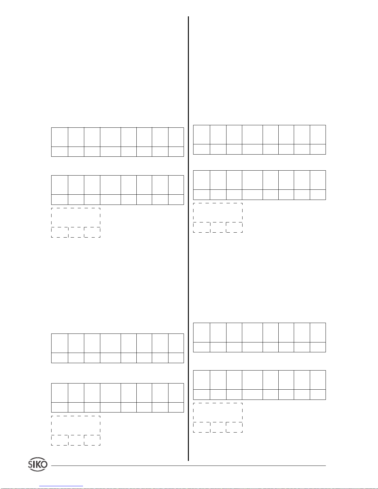
7.7.1 Parameter Positionswert ausgeben
Dieser Parameter ist nur der Vollständigkeit
wegen vorhanden. Die Positions- bzw. Displaywerte der angeschlossenen Geber werden grundsätzlich in der
Data-Exchange
-Phase dem Pro-
fibus-Master übermittelt.
Mit Ausführen dieses Befehls hat man die Möglich-
keit, gezielt einen bestimmten Geber anzusprechen. Dieser Parameter ist nur lesbar, ein Schreibzugriff wird mit einer Fehlermeldung quittiert.
Beispielaufruf:
Positionswert von Geber mit
Adr. 5 lesen
Antwort:
Positionswert = 3A6579H (=3.827.065
Dez
)
7.7.2 Parameter Kalibrierwert schreiben/
lesen
Mit Hilfe dieses Parameters hat der Anwender
die Möglichkeit, den adressierten Geber auf
einen definierten Wert zu setzen bzw. dessen
Kalibrierwert zu lesen. Dieser Wert kann 0, aber
auch jeder beliebige andere Wert (innerhalb des
Darstellungsbereichs von 4 Byte) sein.
Beispielaufruf:
Kalibrierwert von Geber mit Adr.
22 auf 10000H setzen
Antwort:
Befehls- Param.- Param.- Subindex Daten- Daten- Daten- Datencode Index Index (=Adresse) byte 1 byte 2 byte 3 byte 4
Low High
40H 00H 5FH 05H 00H 00H 00H 00H
Befehls- Param.- Param.- Subindex Daten- Daten- Daten- Datencode Index Index (=Adresse) byte 1 byte 2 byte 3 byte 4
Low High
42H 00H 5FH 05H 79H 65H 3AH 00H
Positionswerte der angeschlossenen Geber
xxH xxH
Befehls- Param.- Param.- Subindex Daten- Daten- Daten- Datencode Index Index (=Adresse) byte 1 byte 2 byte 3 byte 4
Low High
23H 01H 5FH 16H 00H 00H 01H 00H
Befehls- Param.- Param.- Subindex Daten- Daten- Daten- Datencode Index Index (=Adresse) byte 1 byte 2 byte 3 byte 4
Low High
60H 01H 5FH 16H 00H 00H 01H 00H
Positionswerte der angeschlossenen Geber
xxH xxH
Im Anschluss an die Programmierung des Kalibrierwertes muss der Anwender den Befehl Soft-
warekalibrierung ausführen, damit der zuvor
programmierte Kalibrierwert Geberintern übernommen wird.
7.7.3 Parameter Offset schreiben/lesen
Dem Positions- bzw. Displaywert kann ein bestimmter Betrag aufaddiert werden (nur gültig bei
SIKONETZ3-Gebern).
Beispielaufruf:
Offsetwert von Geber mit Adr.
12 auf 360
Dez
(= 0168
HEX
) setzen.
Antwort:
7.7.4 Parameter Gerätekennung IF09P lesen
Dieser Parameter ist nur lesbar, ein Schreibzugriff führt zu einer Fehlermeldung. Im Datenbyte
1 steht der Code für das Gerät IF09P (07H), im
Datenbyte 2 wird die Versionsnummer (21H für
V2.01) zur Verfügung gestellt. Die Datenbytes 3
und 4 sind mit 0 belegt.
Beispielaufruf:
Gerätekennung IF09P lesen
Antwort:
Befehls- Param.- Param.- Subindex Daten- Daten- Daten- Datencode Index Index (=Adresse) byte 1 byte 2 byte 3 byte 4
Low High
23H 02H 5FH 0CH 68H 01H 00H 00H
Befehls- Param.- Param.- Subindex Daten- Daten- Daten- Datencode Index Index (=Adresse) byte 1 byte 2 byte 3 byte 4
Low High
60H 02H 5FH 0CH 68H 01H 00H 00H
Positionswerte der angeschlossenen Geber
xxH xxH
Befehls- Param.- Param.- Subindex Daten- Daten- Daten- Datencode Index Index (=Adresse) byte 1 byte 2 byte 3 byte 4
Low High
40H 03H 5FH 00H 00H 00H 00H 00H
Befehls- Param.- Param.- Subindex Daten- Daten- Daten- Datencode Index Index (=Adresse) byte 1 byte 2 byte 3 byte 4
Low High
42H 03H 5FH 00H 07H 21H 00H 00H
Positionswerte der angeschlossenen Geber
xxH xxH
Page 9
IF09P Datum 07.11.2001 Art.Nr. 79121 Z.Nr. 8666013 Änd.Stand 374/01 9
7.7.5 Parameter Status/Konfiguration
(AP09), Zählrichtung (SIKONETZ3)
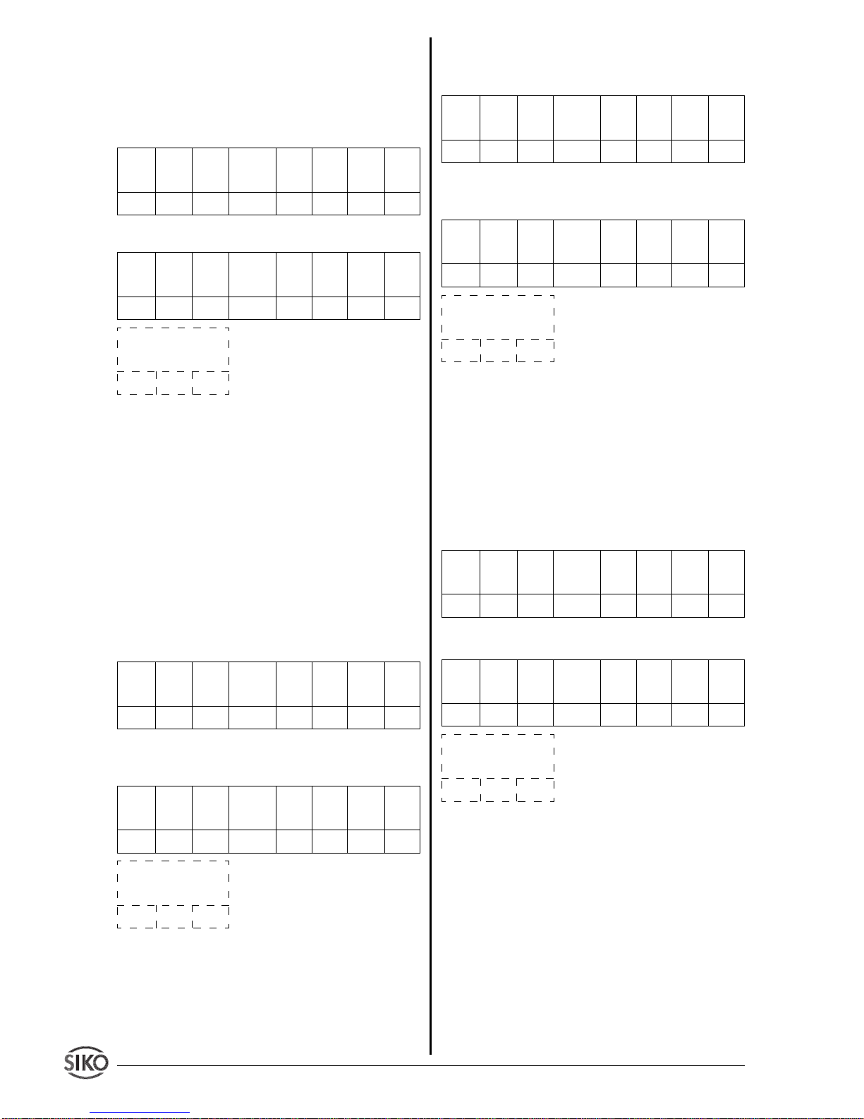
7.7.5.1 Parameter Status lesen (nur AP09)
Mit Hilfe dieser Funktion können von einem
adressiertem AP09 folgende Information ausgelesen werden:
• Batteriestatus
• Tastenmodus
• Drehrichtung
• Nachkommastellen
• Versionsnummer
Datenbyte 4: immer 0
Datenbyte 3: Versionsnummer (z.B.: 2.01)
Datenbyte 2: Anzahl Nachkommastellen (0 ... 3)
Datenbyte 1: Batteriestatus, Tastenmode, Drehrichtung
Beispielaufruf:
Status von Geber mit Adr. 17
lesen
Antwort:
Batterie entladen, Tastenmode = Rücksetzen, Zählrichtung = clockwise, Dezimalpunkt
an 2. Stelle, Version 1.01
00100001
000000XX
Befehls- Param.- Param.- Subindex Daten- Daten- Daten- Datencode Index Index (=Adresse) byte 1 byte 2 byte 3 byte 4
Low High
40H 04H 5FH 11H 00H 00H 00H 00H
Befehls- Param.- Param.- Subindex Daten- Daten- Daten- Datencode Index Index (=Adresse) byte 1 byte 2 byte 3 byte 4
Low High
42H 04H 5FH 11H A1H 02H 11H 00H
Positionswerte der angeschlossenen Geber
xxH xxH
7.7.5.2 Parameter Konfiguration schreiben
(nur AP09)
Hiermit kann die Tastenfunktion und die Drehrichtung festgelegt werden, die Anzahl der Nachkommastellen, die Anzeige zurückgesetzt (auf
0 bzw. auf einen vorher programmierten Kalibrierwert), sowie auf Kettenmaßbetrieb umgeschaltet werden.
Datenbyte 4: immer 0
Datenbyte 3: immer 0
Datenbyte 2: Anzahl Nachkommastellen (0 ... 3)
Datenbyte 1: Tastenmode, Drehrichtung, Rücksetzen,
Kettenaß ausführen
Beispielaufruf:
Der Geber mit der Adresse 14
soll mit folgenden Werten konfiguriert werden:
• Drehrichtung clockwise
• Tastenmode "Rücksetzen"
• 3 Nachkommastellen
Antwort:
7.7.5.3 Parameter Zählrichtung lesen/schreiben (nur SIKONETZ3)
Hiermit wird festgelegt, ob, bei einem Drehgeber, eine steigende Codefolge bei Drehung in
000000XX
Befehls- Param.- Param.- Subindex Daten- Daten- Daten- Datencode Index Index (=Adresse) byte 1 byte 2 byte 3 byte 4
Low High
23H 04H 5FH 0EH 29H 03H 00H 00H
Befehls- Param.- Param.- Subindex Daten- Daten- Daten- Datencode Index Index (=Adresse) byte 1 byte 2 byte 3 byte 4
Low High
60H 04H 5FH 0EH 29H 03H 00H 00H
Positionswerte der angeschlossenen Geber
xxH xxH
X0YY000Z
Drehrichtung:
0= clockwise
1= counter clockwise
}
Tastenmode:
00= Keine Tastenfunktion
01= Kettenmaßfunktion
10= Rücksetzfunktion
11= Sollwertanzeige
Batteriestatus:
0= Batterie OK
1= Batterie leer
00YYUV0Z
Drehrichtung:
0= clockwise
1= counter clockwise
}
Tastenmode:
00= Keine Tastenfunktion
01= Kettenmaßfunktion
10= Rücksetzfunktion
11= Sollwertanzeige
1 = Kettenmaß ausführen
1 = Rücksetzen
Page 10
1 0 IF09P Datum 07.11.2001 Art.Nr. 79121 Z.Nr. 8666013 Änd.Stand 374/01
Uhrzeigersinn (
clockwise, Datenbyte1 = 00H)
oder entgegen dem Uhrzeigersinn (
counter clock-
wise, Datenbyte1 = 01H
) erfolgen soll.
Beispielaufruf:
Zählrichtung von Geber mit Adr.
17 clockwise setzen
Antwort:
7.7.6 Parameter Schritte pro Umdrehung
schreiben/lesen
Über diesen Parameter wird der Messbereich
eines Drehgebers skaliert. Der zulässige Wertebereich ist bei einem 13Bit-Drehgeber 1 .. 8192.
Der Wert 0 wird bei SIKO-Gebern immer als
Maximalwert interpretiert, bei einem 13Bit-Geber also 8192. Werte größer als die durch die
Geberauflösung vorgegebene Anzahl verursachen Schrittfolgen > 1.
Beispielaufruf:
Anzahl Schritte pro Umdr. von
Geber mit Adr.9 lesen
Antwort:
Schrittzahl pro Umdrehung = 3600
Dez
(=
0E10
Hex
)
7.7.7 Parameter Status IF09-P lesen
Der Status des IF09P wird auf die Nutzdatenbytes 1 .. 4 abgebildet. Im Byte 1 steht der Wert 1
für OK und 0 für nicht bereit. Im Byte 2 wird die
Anzahl der angeschlossenen Geber ausgegeben (Wertebereich 0..31), Byte 3 und 4 sind mit
Befehls- Param.- Param.- Subindex Daten- Daten- Daten- Datencode Index Index (=Adresse) byte 1 byte 2 byte 3 byte 4
Low High
23H 04H 5FH 11H 00H 00H 00H 00H
Befehls- Param.- Param.- Subindex Daten- Daten- Daten- Datencode Index Index (=Adresse) byte 1 byte 2 byte 3 byte 4
Low High
60H 04H 5FH 11H 00H 00H 00H 00H
Positionswerte der angeschlossenen Geber
xxH xxH
Befehls- Param.- Param.- Subindex Daten- Daten- Daten- Datencode Index Index (=Adresse) byte 1 byte 2 byte 3 byte 4
Low High
40H 05H 5FH 09H 00H 00H 00H 00H
Befehls- Param.- Param.- Subindex Daten- Daten- Daten- Datencode Index Index (=Adresse) byte 1 byte 2 byte 3 byte 4
Low High
42H 05H 5FH 09H 10H 0EH 00H 00H
Positionswerte der angeschlossenen Geber
xxH xxH
0 belegt.
Beispielaufruf:
Antwort:
IF09P bereit, 31 SIKONETZ-Teilneh-
mer vorhanden
7.7.8 Parameter Softwarekalibrierung/Reset
Hiermit wird der adressierte Geber auf den Kalibrierwert gesetzt. Die Daten in den Nutzdatenbytes 1 .. 4 sind nicht relevant und können auf
beliebige Werte gesetzt sein.
Beispielaufruf:
SIKONETZ-Teilnehmer mit
Adr.13 auf Kal.wert setzen
Antwort:
7.7.9 Parameter System-Status ausgeben/
löschen (nur SIKONETZ3)
Über diesen Parameter kann der Status des
adressierten SIKONETZ-Teilnehmer abgefragt
bzw. gelöscht werden. Die Datenbytes sind wie
folgt zu interpretieren:
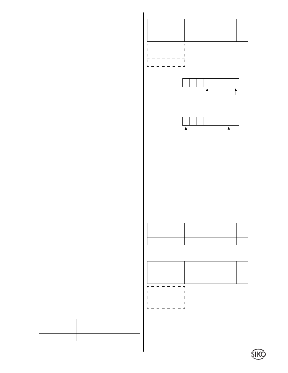
Datenbyte 1:
Bit 0: Aktor 1 ein (Nur bei AP03/1)
Bit 1: Aktor 2 ein (Nur bei AP03/1)
Bit 2: Aktor 3 ein (Nur bei AP03/1)
Befehls- Param.- Param.- Subindex Daten- Daten- Daten- Datencode Index Index (=Adresse) byte 1 byte 2 byte 3 byte 4
Low High
40H 06H 5FH 00H 00H 00H 00H 00H
Befehls- Param.- Param.- Subindex Daten- Daten- Daten- Datencode Index Index (=Adresse) byte 1 byte 2 byte 3 byte 4
Low High
42H 06H 5FH 00H 01H 1FH 00H 00H
Positionswerte der angeschlossenen Geber
xxH xxH
Befehls- Param.- Param.- Subindex Daten- Daten- Daten- Datencode Index Index (=Adresse) byte 1 byte 2 byte 3 byte 4
Low High
23H 07H 5FH 0DH 00H 00H 00H 00H
Befehls- Param.- Param.- Subindex Daten- Daten- Daten- Datencode Index Index (=Adresse) byte 1 byte 2 byte 3 byte 4
Low High
60H 07H 5FH 0DH 00H 00H 00H 00H
Positionswerte der angeschlossenen Geber
xxH xxH
Page 11
IF09P Datum 07.11.2001 Art.Nr. 79121 Z.Nr. 8666013 Änd.Stand 374/01 1 1
Bit 3: Positionswert eingefroren
Bit 4: Tastatur eingeschaltet
Bit 5: Programmierzustand ein
Bit 6: Grenzwertvergleich aktiv
Bit 7: Blockierüberwachung aktiv
Datenbyte 2:
Bit 0: Fehler F01 aufgetreten (Anzeigeüber-
lauf)
Bit 1: Fehler F02 aufgetreten (Datenübertra-
gungsfehler, CRC-Fehler)
Bit 2: Fehler F03 aufgetreten (unzulässiger
oder unbekannter Befehl)
Bit 3: Fehler F05 aufgetreten (unzulässige
Werteingabe)
Bit 4:
Bit 5:
Bit 6:
Bit 7: Achse war blockiert
Datenbyte 3:
Bit 0: Sollwert erreicht (statisch)
Bit 1: Umschaltpunkt erreicht (statisch)
Bit 2: immer 0
Bit 3: immer 0
Bit 4: unterer Grenzwert erreicht (statisch)
Bit 5: oberer Grenzwert erreicht (statisch)
Bit 6: immer 0
Bit 7: Positionierung läuft
Ein gesetztes Bit (= 1) bedeutet aktiv. Die Bit's
0..7 des Datenbyte 1 sind mit einer Schreibanforderung des Befehls
System-Status
nicht lösch-
bar und immer auf dem aktuellen Stand. Die Bit's
0..7 (Byte2) und 0..7 (Byte3) werden automatisch gesetzt, müssen aber mit einer Schreibanforderung des Befehls
System-Status
gelöscht
werden.
Einige Bit's sind nur bei bestimmten SIKO-
NETZ-Geräten vorhanden. Eine detaillierte Beschreibung ist dem
SIKONETZ-Kompendium
zu entnehmen!
Beispielaufruf:
System-Status von Geber mit
Adr.7 lesen
Befehls- Param.- Param.- Subindex Daten- Daten- Daten- Datencode Index Index (=Adresse) byte 1 byte 2 byte 3 byte 4
Low High
40H 08H 5FH 07H 00H 00H 00H 00H
Antwort:
Bedeutung der Datenbytes:
Datenbyte1:
Datenbyte 2: keine aktiven Statusmeldungen
Datenbyte 3:
7.7.10 Sollwert schreiben/lesen
Dieser Befehl wird im Zusammenhang mit Positionieraufgaben verwendet. Hierzu wird der gewünschte Positionswert (= Sollwert) programmiert und mit dem weiter unten beschriebenen
Befehl
Positionieren starten
die Positionierung
in Gang gesetzt. Voraussetzung hierzu ist natürlich ein entsprechender Systemaufbau z.B. mit
SIKONETZ-Drehgeber vom Typ AP03/1.
Beispielaufruf:
Sollwert von Geber mit Adr. 6
lesen
Antwort:
Sollwert = 25000
Dez
(= 61A8
Hex
)
7.7.11 Tastatur einschalten (nur SIKONETZ3)
Hiermit kann bei Geräten, die über ein Tastenfeld verfügen, diese wieder eingeschaltet werden, ein entsprechendes vorhergehendes ausschalten vorausgesetzt.
Die Nutzdatenbytes 1
.. 4 können beliebige Werte enthalten (im Bei-
Befehls- Param.- Param.- Subindex Daten- Daten- Daten- Datencode Index Index (=Adresse) byte 1 byte 2 byte 3 byte 4
Low High
42H 08H 5FH 07H 11H 00H 82H 00H
Positionswerte der angeschlossenen Geber
xxH xxH
Tastatur
eingeschaltet
Aktor 1 ein
00010001
Positionierung
läuft
Umschaltpunkt
erreicht
10000010
Befehls- Param.- Param.- Subindex Daten- Daten- Daten- Datencode Index Index (=Adresse) byte 1 byte 2 byte 3 byte 4
Low High
40H 0AH 5FH 06H 00H 00H 00H 00H
Befehls- Param.- Param.- Subindex Daten- Daten- Daten- Datencode Index Index (=Adresse) byte 1 byte 2 byte 3 byte 4
Low High
42H 0AH 5FH 06H A8H 61H 00H 00H
Positionswerte der angeschlossenen Geber
xxH xxH
Page 12
1 2 IF09P Datum 07.11.2001 Art.Nr. 79121 Z.Nr. 8666013 Änd.Stand 374/01
spiel gekennzeichnet durch xxH).
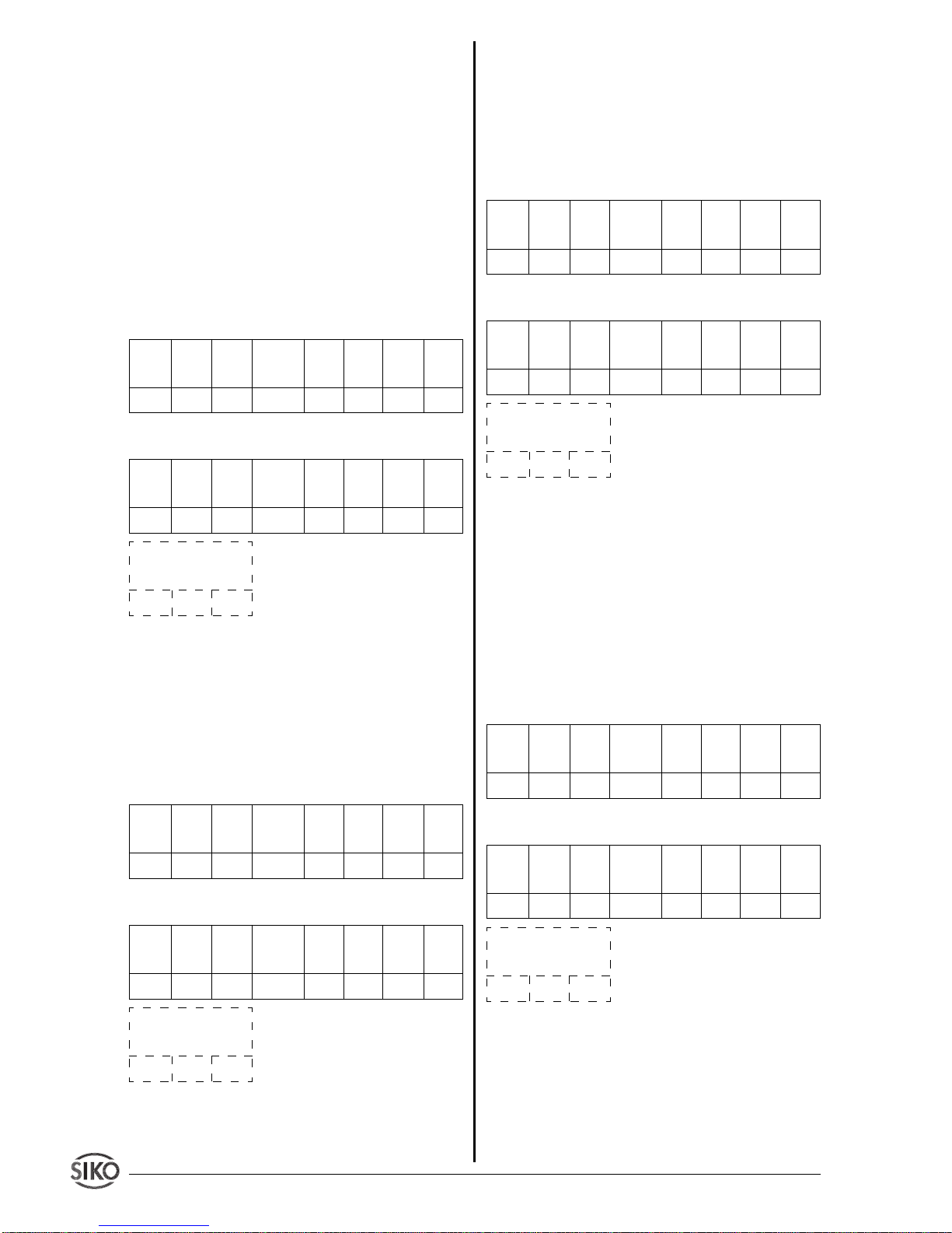
Dieser Befehl
ist
Rundruf
-fähig. Durch setzen von Bit 6 im Byte
Subindex
können sämtliche SIKONETZ-Teilnehmer adressiert werden. Ist das Bit 6 nicht
gesetzt, wird nur der Teilnehmer mit der im Byte
Subindex
angegeben Adresse angesprochen.
Es reicht also nicht, in diesem Byte nur das Bit
6 zu setzen, es muss grundsätzlich in den Bits
0 .. 5 ein der Adresse entsprechender Wert
eingetragen werden!
Beispielaufruf:
Die Tastaturen aller SIKONETZ-
Teilnehmer sollen eingeschaltet werden. (Feld
Subindex
muss einen Wert zwischen 01H und
1FH enthalten)
Antwort:
7.7.12 Tastatur ausschalten (nur SIKONETZ3)
Befehl, um an einem oder allen SIKONETZTeilnehmer, soweit vorhanden, die Tastatur auszuschalten. (Rundruffähig, siehe
7.7.11
)
Beispielaufruf:
Tastatur ausschalten, Gerät mit
Adresse 02H
Antwort:
7.7.13 Positionieren starten (nur SIKONETZ3)
Der Befehl wird in Verbindung mit Positionierfä-
Befehls- Param.- Param.- Subindex Daten- Daten- Daten- Datencode Index Index (=Adresse) byte 1 byte 2 byte 3 byte 4
Low High
23H 0BH 5FH 41H xxH xxH xxH xxH
Befehls- Param.- Param.- Subindex Daten- Daten- Daten- Datencode Index Index (=Adresse) byte 1 byte 2 byte 3 byte 4
Low High
60H 0BH 5FH 41H xxH xxH xxH xxH
Positionswerte der angeschlossenen Geber
xxH xxH
Befehls- Param.- Param.- Subindex Daten- Daten- Daten- Datencode Index Index (=Adresse) byte 1 byte 2 byte 3 byte 4
Low High
23H 0CH 5FH 02H xxH xxH xxH xxH
Befehls- Param.- Param.- Subindex Daten- Daten- Daten- Datencode Index Index (=Adresse) byte 1 byte 2 byte 3 byte 4
Low High
60H 0CH 5FH 02H xxH xxH xxH xxH
Positionswerte der angeschlossenen Geber
xxH xxH
higen SIKONETZ-Teilnehmern verwendet, um
eine gewünschte, mit dem oben beschriebenen
Befehl
Sollwert schreiben
vorgegebene, Position anzufahren. Der Inhalt der Nutzdatenbytes 1
.. 4 ist ohne Bedeutung.
Beispielaufruf:
Positionierung starten, Gerät mit
Adr. 23
Dez
(=17H)
Antwort:
7.7.14 Positionieren stoppen (nur SIKONETZ3)
Mit diesem Befehl wird ein zuvor in Gang gesetzter Positioniervorgang gestoppt. Der Inhalt der
Nutzdatenbytes 1 .. 4 ist ohne Bedeutung (Rundruffähig, siehe
7.7.11
).
Beispielaufruf:
Positionierung stoppen, es werden alle SIKONETZ-Geräte angesprochen, unabhängig von der im Feld
Subindex
angegebe-
nen Adresse.
Antwort:
7.7.15 Anzeige (Display) einschalten (nur
SIKONETZ3)
Hiermit wird bei Geräten mit Display die Anzeige
eingeschaltet. Der Inhalt der Nutzdatenbytes 1 ..
4 ist ohne Bedeutung. (Rundruffähig, siehe
7.7.11
)
Befehls- Param.- Param.- Subindex Daten- Daten- Daten- Datencode Index Index (=Adresse) byte 1 byte 2 byte 3 byte 4
Low High
23H 0DH 5FH 17H xxH xxH xxH xxH
Befehls- Param.- Param.- Subindex Daten- Daten- Daten- Datencode Index Index (=Adresse) byte 1 byte 2 byte 3 byte 4
Low High
60H 0DH 5FH 17H xxH xxH xxH xxH
Positionswerte der angeschlossenen Geber
xxH xxH
Befehls- Param.- Param.- Subindex Daten- Daten- Daten- Datencode Index Index (=Adresse) byte 1 byte 2 byte 3 byte 4
Low High
23H 0EH 5FH 41H xxH xxH xxH xxH
Befehls- Param.- Param.- Subindex Daten- Daten- Daten- Datencode Index Index (=Adresse) byte 1 byte 2 byte 3 byte 4
Low High
60H 0EH 5FH 41H xxH xxH xxH xxH
Positionswerte der angeschlossenen Geber
xxH xxH
Page 13
IF09P Datum 07.11.2001 Art.Nr. 79121 Z.Nr. 8666013 Änd.Stand 374/01 1 3
Beispielaufruf:
Anzeige einschalten, es werden
alle SIKONETZ-Geräte angesprochen, unabhängig von der im Feld
Subindex
angegebenen
Adresse.
Antwort:
7.7.16 Anzeige (Display) ausschalten (nur
SIKONETZ3)
Hiermit wird bei Geräten mit Display die Anzeige
ausgeschaltet. Der Inhalt der Nutzdatenbytes 1
.. 4 ist ohne Bedeutung. (Rundruffähig, siehe
7.7.11
).
Beispielaufruf:
Anzeige ausschalten, es werden
alle SIKONETZ-Geräte angesprochen, unabhängig von der im Feld
Subindex
angegebenen
Adresse.
Antwort:
7.8 Fehlercodes
In einem Fehlerfall (ungültiger Befehlsindex,
ungültige Adresse, ungültiger Zugriff z.B. Write
Request auf Read-Variable oder Kommunikationsfehler zwischen IF09P und den Gebern) wird
anstatt eines Write bzw. Read Response ein
Error Response und in den Nutzdatenbytes eine
entsprechende Fehlernummer zurückgegeben.
Befehls- Param.- Param.- Subindex Daten- Daten- Daten- Datencode Index Index (=Adresse) byte 1 byte 2 byte 3 byte 4
Low High
23H 0FH 5FH 41H xxH xxH xxH xxH
Befehls- Param.- Param.- Subindex Daten- Daten- Daten- Datencode Index Index (=Adresse) byte 1 byte 2 byte 3 byte 4
Low High
60H 0FH 5FH 41H xxH xxH xxH xxH
Positionswerte der angeschlossenen Geber
xxH xxH
Befehls- Param.- Param.- Subindex Daten- Daten- Daten- Datencode Index Index (=Adresse) byte 1 byte 2 byte 3 byte 4
Low High
23H 10H 5FH 41H xxH xxH xxH xxH
Befehls- Param.- Param.- Subindex Daten- Daten- Daten- Datencode Index Index (=Adresse) byte 1 byte 2 byte 3 byte 4
Low High
60H 10H 5FH 41H xxH xxH xxH xxH
Positionswerte der angeschlossenen Geber
xxH xxH
Befehls- Daten- Daten- Bedeutung
code byte 7 byte 8
80H 6 6 Falscher Index
80H 5 6 Falscher Subindex
(=AP09 bzw. SIKONETZ-Adresse)
80H 3 6 Zugriff verweigert
z.B. Write Request
auf Read-Variable
oder Parameter nicht
vorhanden.
80H 4 6 Rundruf bei diesem
Befehl nicht erlaubt.
80H 1 6 Kommunikationsfeh-
ler zwischen IF09P
und RS485-Bus (Verbindung unterbrochen oder Checksummenfehler)
Beispiel:
Parameter
Anzeige pro Umdrehung
auf
Gerät mit Adresse größer 31
Dez
schreiben z.B.
72
Dez
(=48H)
Antwort:
Error Response, falscher Subindex( =
falsche Adresse)
Die Fehlermeldung mit dem Code 80H im Feld
Befehlscode
bleibt solange bestehen, bis der
Befehl mit den korrekten Parametern ausgeführt
wurde.
Befehls- Param.- Param.- Subindex Daten- Daten- Daten- Datencode Index Index (=Adresse) byte 1 byte 2 byte 3 byte 4
Low High
23H 05H 5FH 48H 00H 20H 00H 00H
Befehls- Param.- Param.- Subindex Daten- Daten- Daten- Datencode Index Index (=Adresse) byte 1 byte 2 byte 3 byte 4
Low High
80H 05H 5FH 48H 00H 00H 05H 06H
Positionswerte der angeschlossenen Geber
xxH xxH
Page 14

1 4 IF09P Datum 07.11.2001 Art.Nr. 79121 Z.Nr. 8666013 Änd.Stand 374/01
Page 15
IF09P Datum 07.11.2001 Art.Nr. 79121 Z.Nr. 8666013 Änd.Stand 374/01 1 5
ENGLISH
1. Warranty information
In order to carry out installation correctly, we
strongly recommend this document is read
very carefully. This will ensure your own safety and the operating reliability of the device.
• Your device has been quality controlled,
tested and is ready for use. Please respect all
warnings and information which are marked
either directly on the device or specified in this
document.
• Warranty can only be claimed for components supplied by SIKO GmbH. If the system is
used together with other products, there is no
warranty for the complete system.
• The guarantee period is 6 months starting
with the date of invoice.
• Repairs should be carried out only at our
works. If any information is missing or unclear,
please contact the SIKO sales staff.
2. Identification
Please check particular type of unit and type
number from the identification plate. Type
number and the corresponding execution are
indicated in the delivery documentation.
e.g. IF09P-0023
version number
type of unit
User Information
IF09P
Profibus Interface
3. System design
The Profibus-Gateway IF09P was mainly designed to link SIKO type AP09 position sensors
to the PROFIBUS-DP. Optionally, there is the
possibility to connect devices with SIKONETZ3
interface to the PROFIBUS-DP. AP09 and SIKONETZ3 cannot share, however one common
connection. The selection of the two interface
protocols is via a DIP switch on the IF09P.
Fig. 1 : System design (IF09P with AP09)
Fig. 2 : System design (IF09P with SIKONETZdevices)
Profibus-DP
PROFIBUS-Slave,
e.g.: ET200B
Master-SPS,
e.g.:SIEMENS
S7-315
IF09P
SIKONETZ3
WK58
MA10/3
AP03/1
IF09P
AP09
AP09
AP09
AP09
RS485-Bus
Profibus-DP
PROFIBUS-Slave,
e.g.: ET200B
Master-SPS,
e.g.:SIEMENS
S7-315
Page 16
1 6 IF09P Datum 07.11.2001 Art.Nr. 79121 Z.Nr. 8666013 Änd.Stand 374/01
4. Installation
For mounting, the degree of protection specified
must be observed. If necessary, protect the unit
against environmental influences such as
sprayed water, dust, knocks, extreme temperatures.
IF09P has been designed for mounting on
standrad rails 35x7.5 accord. to DIN 50022. For
mounting snap the retainer onto the rail and
ensure that the lock is at the device's underside.
For dismounting, the lock is pushed downward.
Fig.3: Installation
5. Electrical connection
• If the unit is used in combination with drive
systems, additional safety protection must be
used (eg. limit switches or other interlocking
systems).
• Wiring must only be carried out with power off.
• Provide standed wires with ferrules.
• Check all lines and connections before switching on the equipment.
Interference and distortion
All connections are protected against the effects
of interference. The location should be selec-
ted to ensure that no capacitive or inductive
interferences can affect the encoder or the
connection lines! Suitable wiring layout and
choice of cable can minimise the effects of
interference (eg. interference caused by SMPS,
motors, cyclic controls and contactors).
Necessary steps:
• Only screened cable should be used. Screen
should be connected to earth at both ends. Wire
cross section is to be at least 0,14 mm2, max.
0,5 mm2.
• Wiring to screen and to ground (0V) must be
via a good earth point having a large surface area
for minimum impedance.
• The unit should be positioned well away from
cables with interference; if necessary a protec-
tive screen or metal housing must be provided. The running of wiring parallel to the mains
supply should be avoided.
• Contactor coils must be linked with spark
suppression.
• PE- connection with 2.5– 4 mm2 via PE-connector (quick-connect receptacle 6,3x0,8).
• With data transmission max. allowable cable
lengh is 200m.
Technical data
• power supply 24VDC ±20%
• power consumption approx. 1.8W
• DC/DC converter for DC-isolated DP interface
• micro-controller 80C528
• Siemens SPC3 controller
• baud rate up to 12 Mbit/s.
• 7 Bit address to be set via a DIP switch.
(Profibus user address)
Connection of power supply:
via the 3-pin terminal strip on front of the device.
ATTENTION: To be EMC-compatible it is necessary to establish a low-impedance connection to the potential matching system via a 6.3
mm flat connector!
LED Power Good: indicates that the internal
supply voltage is within the tolerable range.
LED DE: shows the status "Data Exchange" on
the profibus.
Power supply
PE-connector
Power
Good
DE
Page 17
IF09P Datum 07.11.2001 Art.Nr. 79121 Z.Nr. 8666013 Änd.Stand 374/01 1 7
Connection Sensor (Geber)
Pin Description
1 +UB 24VDC
2 N.C.
3 DÜA
4 N.C.
5 GND
6 N.C.
7 N.C.
8 DÜB
9 N.C.
Connection Profibus
Pin Description
1 N.C.
2 N.C.
3 B-Line
4 RTS
52M
6 2P5
7 N.C.
8 A-Line
9 N.C.
Power supply
Pin Description
1PE
20V
3 +24VDC ± 20%
6. Features
6.1 Profibus interface
The connection of the IF09P to the Profibus
is via a 9 pin DSUB connector according to
EN 50170. If a bus must be terminated this
must be done in the connector, i. e. appropriate connectors with terminators that can be
switched in should be used. The following bit
rates are supported: 9.6kBit/s, 19.2kBit/s,
93.75kBit/s, 187.5kBit/s, 500kBit/s, 1.5MBit/
s, 3MBit/s, 6MBit/s und 12Mbit/s. Further
profibus-specific parameters are included in
the corresponding device database file
SIKO00EC.GSD which is available on request or may be downloaded from the internet location http://www.siko.de/download
6.2 Interface to AP09 or SIKONETZ3
(connection Sensor "Geber")
The hardware interface to the sensors (AP09 or
SIKONETZ3 devices, resp.) is mounted on a 9
pin DSUB connector and is based on the RS485
standard. The baud rate of the AP09 protocol is
115.2kbit/s, and 19.2kbit/s with the SIKONETZ3
protocol. The connected sensors can be powered via two additional pins.
The connection current must not exceed 1A !
6.3 Function
During the data exchange phase, the IF09P polls
the positional values from the connected sensors. These are made available to the master
station (e. g. Siemens S7) via Profibus protocol
chip SPC3.
Furthermore, there is the possibility to parametrize the connected sensors via specific commands in the Master-SPS, to conduct status
queries or have executed system commands.
Further below you will find a description of the
data telegrams and of the command table.
Fault conditions such as wrong parameters,
wrong station addresses or communication errors are identified by the IF09Pand communicated to the master SPS through error codes in the
data telegram.
6.3.1 Start phase
If all devices, IF09P and the sensors (AP09 or
SIKONETZ3 stations, respectively) are turned
on at the same time, the following switch-on
sequence will run.
• The SIKONETZ stations are initialized.
• The IF09P is initialized as well and waits
approx. 2,5 s until the sensors are initialized.
• Now, the IF09P identifies the number of connected sensors.
IMPORTANT NOTE:
The sensors must be set
in ascending address sequence, starting with
address 1! There must be no address "gaps"!
The respective user manuals will inform you on
how to set the addresses of the sensors.
6.3.2 Operation phase
• After identifying the number of connected
sensors, the PROFIBUS interface is intial-ized.
Afterwards, the position values of the sensors
are requested from the sensors in a program loop
and made available to the Profibus interface.
6.3.3 Parameterization phase
• When the master SPS sends an parameterization request to the IF09P, the query of the
position value is suppressed until the parameterization request has been processed. The pro-
Page 18
1 8 IF09P Datum 07.11.2001 Art.Nr. 79121 Z.Nr. 8666013 Änd.Stand 374/01
cessing of the request is communicated to the
master SPS via confirmation code.
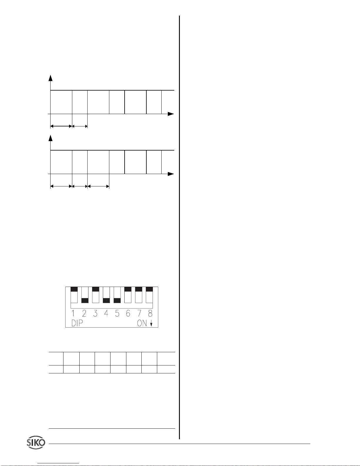
6.4 Cycle times
The temporal sequence of the position-value
query and the operation of the Profibus interface
is shown in the diagram below (AP09 protocol !):
The signX behind an indicated time means a
longer duration with SIKONETZ3 operation due
to its lower baud rate !
7. Operation
7.1 Setting the address (Profibus-slave
address)
By means of the DIP switches SW1/1..SW1/7
the Profibus-slave address of the IF09P is set.
The slave addresses 0..125 are permissible.
Fig. 4 : Address switch
Valency
1 2 4 8 1 6 3 2 64 proto-
col type
SW1/1 SW1/2 SW1/3 SW1/4 SW1/5 SW1/6 SW1/7 SW1/8
Example for setting an address:
Desired address = 26
dec
(= 1A
hex
)
SW1/5 = ON (valency 16)
+ SW1/4 = ON (valency 8)
+ SW1/2 = ON (valency 2)
address 16+8+2 = 26
dec
All other switches (SW1/1, SW1/3, SW1/6 and
SW1/7) remain in the position OFF in this case.
7.2 Toggling of the sensor interface protocols
Sensors with AP09 as well as SIKONETZ3
protocol may be optionally connected to an
RS485 interface. The desired protocol is set by
means of switch SW1/8 :
SW1/8 = OFF: AP09 protocol
SW1/8 = ON: SIKONETZ3 protocol
Changing the DIP switch during operation is not
recognized. The switch status is identified exclusively during turning on!
7.3 Termination of the PROFIBUS-DP
connection
The line must be terminated at the first and last
bus station by means of three resistors which
are to be connected as follows:
390 Ohm between PIN6 (2P5) and PIN3 (B line)
390 Ohm between PIN8 (A line) and PIN5 (2M)
220 Ohm between PIN3 (B line) and PIN8 (A
line).
If connectors with a built-in line termination are
used, this must be turned on at the first and last
bus station.
7.4 Configuration
A device database file named SIKO00EC.GSD
was generated for the ROFIBUS-DP gateway.
This file can be integrated into the device library
with the configuration tool used, e. g. COM
PROFIBUS (V3.3 or better) for the PROFIBUSDP PC card CP5412A2 of the Siemens company or the appropriate configuration tool for SPS
(e.g. S7) (the corresponding procedures should
be taken from the respective user information).
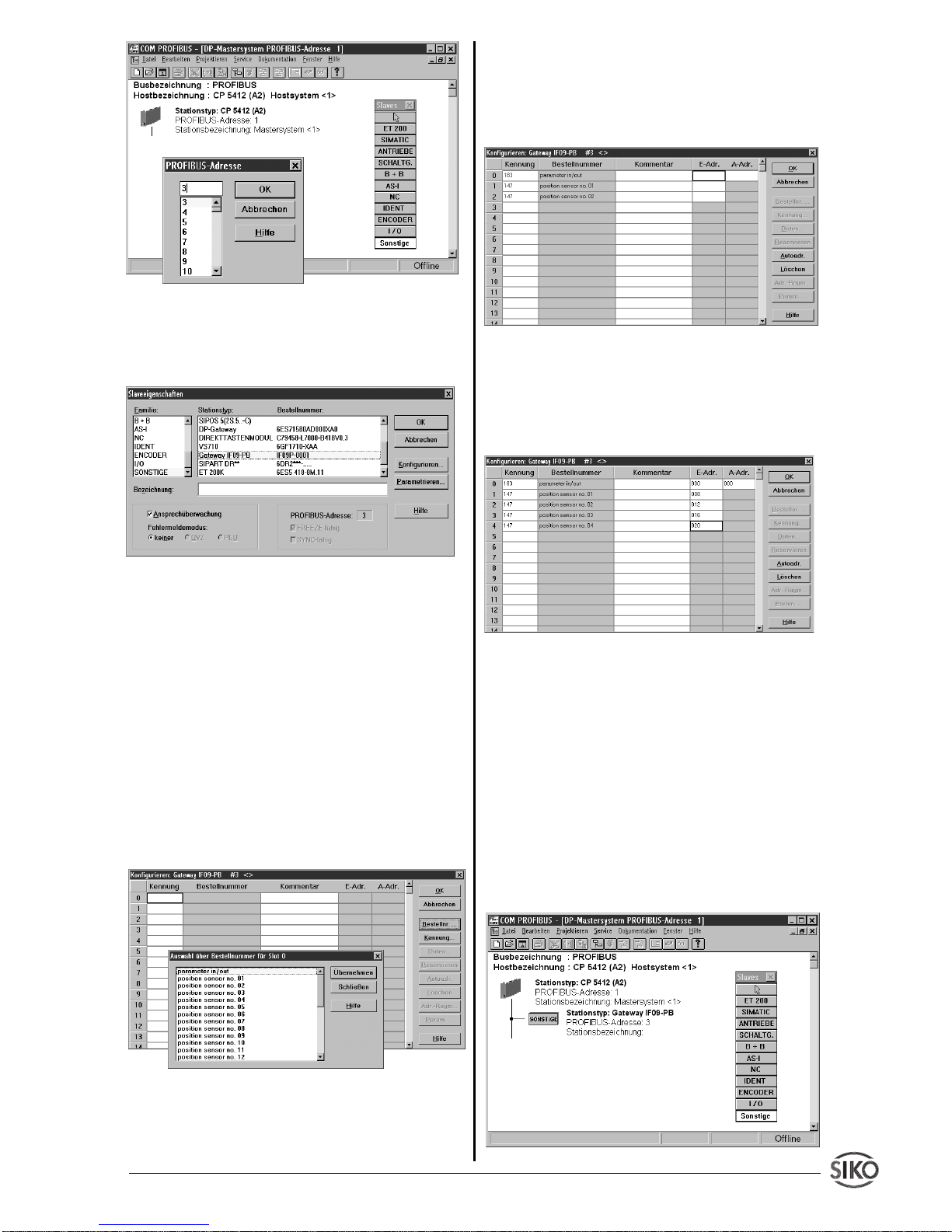
The following example configuration serves to
illustrate the procedure of integrating the IF09P
into a profibus unit. The
COM-PROFIBUS
software is used as configuration tool. The following
conditions are assumed:
1) The device database file (
SIKO00EC.GSD
) is
in the correct directory and
2) at least 1 master assembly was selected.
Position
value
query
addr. n
Profibus
Position
value
query
addr. n+1
Profibus
Position
value
query
addr. n+ 2
Profibus
appr.
3,8ms
X
appr.
2ms
Position
value
query
addr. n
Profibus
Edit
parametrization
Profibus
Position
value
query
addr. n+ 1
Profibus
appr.
3,8ms
X
appr.
2ms
appr.
3..20ms
X
Page 19
IF09P Datum 07.11.2001 Art.Nr. 79121 Z.Nr. 8666013 Änd.Stand 374/01 1 9
1st step: Selection of the profibus station to be
included (here: gateway IF09P). It is found under
the heading "Others".
After selecting this item the desired station
address is queried. The selected address must
be the same as the address set in the IF09P !
2nd step: Select gateway IF09P from the offered list. By clicking on "Configure…", the
gateway is adjusted to the planned assembly.
3rd step: Configuration of the gateway. The
IF09P is a modular slave, where the module
"Parameter In/Out"
must alsways be entered as
the 1st module during configuartion. By clicking
on the menu item "Order No. ..." another win-
dows is opened which shows the modules that
can be entered.
The connected sensors and the gateway itself
are parameterized via the module
"Parameter In/
Out"
.
The selected module is taken over into the
identification list by clicking on the
"Accept"
button. Afterwards, the modules
"position sen-
sor no. xx"
are taken over into the remaining
positions.
In the fields
"E-Adr."
and
"A-Adr."
an address in
the range of 000...240 must be entered now
where the data are to be filed. In the simple case,
this address allocation can be executed automatically using the menu item
"Autoadr."
.
It is imperative that the sensor addresses are
always entered in ascending sequence. This
sequence is also used by the gateway for enquiring the sensors and for recording the position
values in the data telegram.The configuration
menu is completed by clicking on
"OK".
Now,
the IF09P is registered and configured as
profibus station.
All further settings are conducted automatically
via the device database file, e.g. whether the
profibus station supports the global commands
"Freeze"
or
"Sync"
.
Page 20
2 0 IF09P Datum 07.11.2001 Art.Nr. 79121 Z.Nr. 8666013 Änd.Stand 374/01
12345678
7.5 Telegram setup in the DATA-EXCHANGE
state
With the PROFIBUS-DP, parameterization of a
slave during the DATA-EXCHANGE phase is
severely restricted. Furthermore, parameters
are never readable with the PROFIBUS-DP.
Normally, a slave is only once parameterized
during start-up. During configuration, these parameters must be defined by means of an appropriate software tool (see section 7.3).
During operation, only input and output data are
exchanged between master and slave . In order
to enable the exchange of parameters, the first
8 data bytes ("parameter in/out") are used for
parameter transfer in the send/receive telegram.
Data telegram from master to IF09P:
Length = 8 bytes, contains parameterization
data and control commands.
Data telegram from IF09P to master:
Length = 8 bytes status/parameterization data +
number_sensors* 4 bytes (= max. 31*4+8 bytes
= 132 bytes)
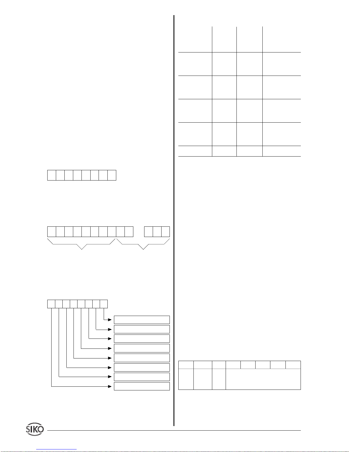
Setup of the 8 Bytes of the data telegram
(applies do data direction master -> IF09P as
well as IF09P -> master)
Byte no.
Byte 1 : Command code
Command
Command
Command
Meaning
code code
(Service) (hexa-
(decimal)
decimal)
Write Request
23H 35 Send parame-
ter to gateway
IF09P
Write Response
60H 96 Gateway IF09P
response to
Write Request
Read Request
40H 64 Request of a
parameter from
gateway IF09P
Read Response
42H 66 Response to
request with
current value
Error Response
80H 128 Error message
The command code is set to 00H during regular
data exchange operation.
Bytes 2, 3: Parameter index
The parameter index is entered in the Intel data
format in the user data byte 2 (low byte) and in
the user data byte 3 (high byte). (Description:
see
item 7.6 command list
)
Byte 4: Sub-index
The parameter
Sub-index
represents the address
of the AP09 or SIKONETZ station which is to be
addressed via the IF09P. The value range is
0..31. (0 = gateway IF09P, 1..31 = connected
sensors).
The following statement is restricted to the
use of the SIKONETZ3 protocol:
By means of the bit at the position
Bit 6 (broad-
cast)
control is possible whether or not the
command shall apply to all stations. If the bit is
set (=1), the address (of the SIKONETZ3 station) is ignored, otherwise the command applies
only to the device with the indicated address. If
the value 0 is entered as address, then the
broadcast bit is ignored. Please refer to the
command list,
section 7.6
, to see which com-
mands are able to broadcast.
Bytes 5..8: Data byte1..data byte 4
In the data domain, the value of the parameter is
entered in the left-aligned Intel format. (byte 5 =
low byte .. byte 8 = high byte)
12345678
Data byte 2
Data byte 3
Data byte 4 (high byte)
Data byte 1 (low byte)
Parameter index (low byte)
Parameter index (high byte)
Sub-index (= address)
Command code
12345678
...
Status / control data Service data
Bit 7 Bit 6 Bit 5 Bit 4 Bit 3 Bit 2 Bit 1 Bit 0
0 multi- 0 address 1 .. 31
addr.
bit
Page 21
IF09P Datum 07.11.2001 Art.Nr. 79121 Z.Nr. 8666013 Änd.Stand 374/01 2 1
1)
The contents of the user data bytes are
irrelevant.
2)
Write access deletes the system status of the
addressed sensor.
3)
Read/write access with this index generates
an error message
4)
These commands are
broadcast
able.
5)
These parameters are not enabled with AP09,
thus they generate an error message
Access = R: only read access possible.
Access = W: only write access possible.
Access = R/W: read and write access possible.
All values are displayed in the Intel format.
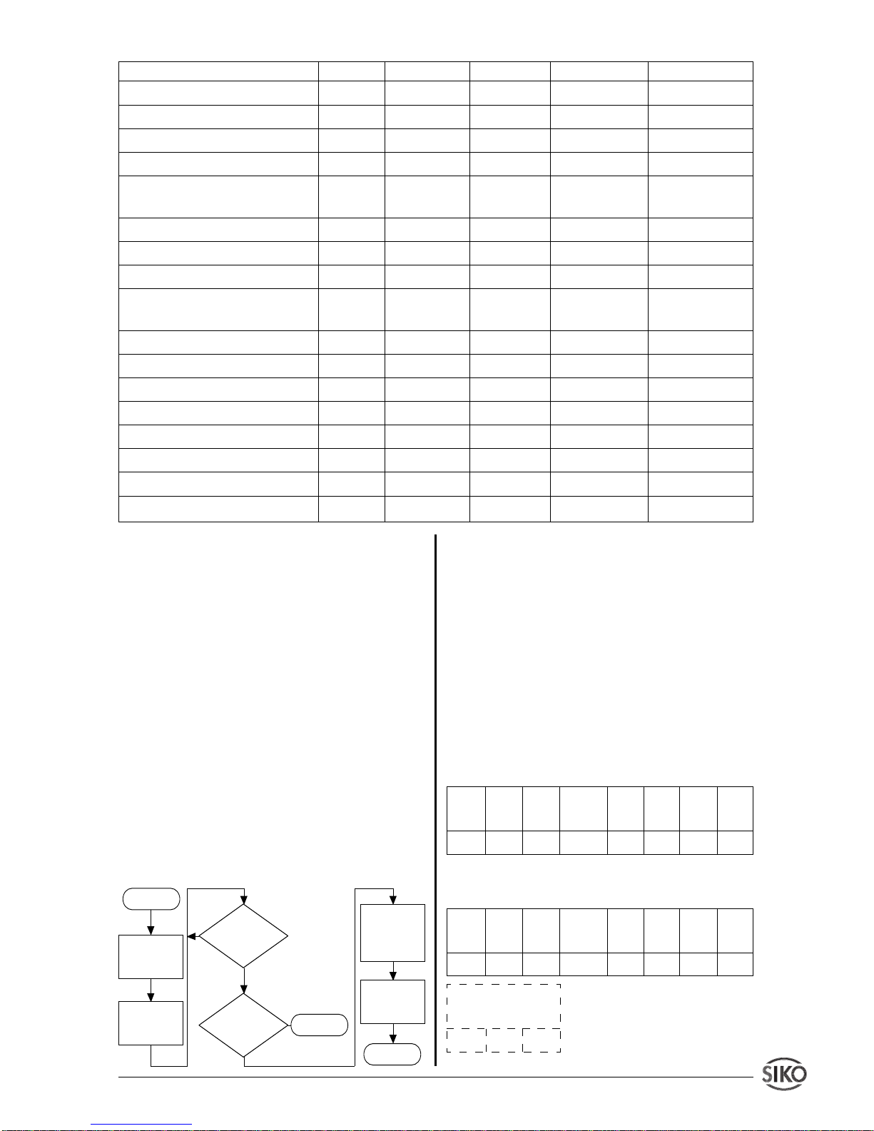
7.7 Command (flowchart)
The basic procedure of parameterization is illustrated in the following flowchart:
7.7.1 Output position value parameter
This parameter exists only for the sake of
completeness. The positions or display values
of the attached sensors are always transmitted
to the profibus master in the
Data-Exchange
phase.
By executing this command it is possible to
access a specific sensor. This parameter is only
readable, a write-access attempt induces an
error message.
Example command:
Read position value of en-
coder, address 5.
Response:
position value = 3A6579H
(=3.827.065
dec
)
7.6 Command list (index table)
Parameter Index Subindex Data type Data length Access
Position value 5F00H 1..31 Integer32 4 R
Calibration value 5F01H 1..31 Integer32 4 R/W
Offset
5)
5F02H 1..31 Integer32 4 R/W
Device identification IF09-P 5F03H 0 Integer32 4 R
Count direction (SIKONETZ3) 5F04H 1..31 Integer32 4 R/W
status/configuration (AP09)
Steps per revolution 5F05H 1..31 Integer32 4 R/W
Status IF09-P 5F06H 0 Integer32 4 R
Software calibration/reset 5F07H 1..31 Integer32 4 W
1)
System status SIKONETZ- 5F08H 1..31 Integer32 4 R/W
1)2)
encoder
Not implemented
3)
5F09H - - - Desired value 5F0AH 1..31 Integer32 4 W
Enable keyboard
1)4)5)
5F0BH 1..31 Integer32 4 W
Disable keyboard
1)4)5)
5F0CH 1..31 Integer32 4 W
Start positioning
5)
5F0DH 1..31 Integer32 4 W
Stop positioning
1)4)5)
5F0EH 1..31 Integer32 4 W
Enable display
1)4)5)
5F0FH 1..31 Integer32 4 W
Disable display
1)4)5)
5F10H 1..31 Integer32 4 W
No
Yes
Start
ERROR
End
Prepare
data telegram
Send telegram to
IF09P
Send telegram to
IF09P
Prepare
data telegram with
0
Response
received?
Error message ?
No
Yes
Com- Param. Param. Sub-index Data Data Data Data
mand Index Index ( =ad dress) byte 1 byte 2 byte 3 byte 4
code Low High
40H 00H 5FH 05H 00H 00H 00H 00H
Com- Param. Param. Sub-index Data Data Data Data
mand Index Index (=address) byte 1 byte 2 byte 3 byte 4
code Low High
42H 00H 5FH 05H 79H 65H 3AH 00H
Position values of the
connected encoders
xxH xxH
Page 22
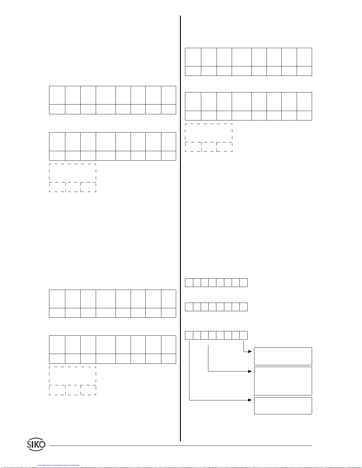
2 2 IF09P Datum 07.11.2001 Art.Nr. 79121 Z.Nr. 8666013 Änd.Stand 374/01
7.7.2 Read / write calibration value parameter
The user has the possibility to set the addressed
sensor to a defined value or to reads its calibration value by means of this parameter. This
value may be 0 or any other value (within the
presentation range of 4 byte).
Example call:
Set calibration value of sensor,
address 22, to10000H
Response:
Programming the calibration value is followed by
executing the command software calibration
so that the pre-programmed calibration value is
accepted in the sensor.
7.7.3 Read / write offset parameter
A specific amount may be added to the position
or display value, respectively (applies only to
SIKONETZ3 sensors).
Example call:
Set offset value of sensor, addr.
12, to 360
dec
(= 0168
HEX
).
Response:
7.7.4 Read IF09P device identification parameter
This parameter is read-only, a write access
attempt causes an error message. The code for
the device IF09P is in the data byte 1(07H), in
data byte 2 the version number (21H for V2.01)
is supplied. Data bytes 3 and 4 are assigned 0.
Example call:
Read IF09P device identification
Response:
7.7.5 Parameters status/configuration
(AP09), counting direction (SIKONETZ3)
7.7.5.1 Read status parameter (onlyAP09)
By means of this function the following information can be read from an addressed AP09:
• Battery status
• Key mode
• Direction of rotation
• Number of digits after decimal point
• Version number
Data byte 4: always 0
Data byte 3: version number (e.g. 2.01)
Data byte 2: Number of digits after decimal point (0 ... 3)
Data byte 1: battery status, key mode, direction of rotation
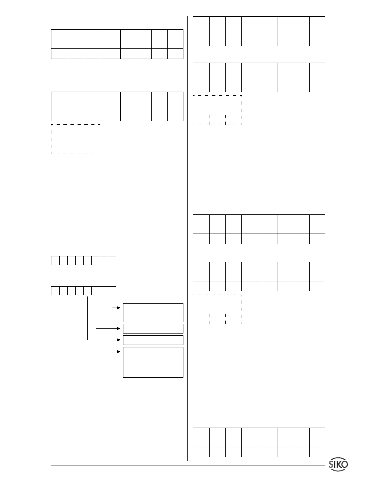
00100001
000000XX
Com- Param. Param. Sub-index Data Data Data Data
mand Index Index (=address) byte 1 byte 2 byte 3 byte 4
code Low High
23H 01H 5FH 16H 00H 00H 01H 00H
Com- Param. Param. Sub-index Data Data Data Data
mand Index Index (=address) byte 1 byte 2 byte 3 byte 4
code Low High
60H 01H 5FH 16H 00H 00H 01H 00H
Position values of the
connected encoders
xxH xxH
Com- Param. Param. Sub-index Data Data Data Data
mand Index Index (=address) byte 1 byte 2 byte 3 byte 4
code Low High
23H 02H 5FH 0CH 68H 01H 00H 00H
Com- Param. Param. Sub-index Data Data Data Data
mand Index Index (=address) byte 1 byte 2 byte 3 byte 4
code Low High
60H 02H 5FH 0CH 68H 01H 00H 00H
Position values of the
connected encoders
xxH xxH
Com- Param. Param. Sub-index Data Data Data Data
mand Index Index (=address) byte 1 byte 2 byte 3 byte 4
code Low High
40H 03H 5FH 00H 00H 00H 00H 00H
Com- Param. Param. Sub-index Data Data Data Data
mand Index Index (=address) byte 1 byte 2 byte 3 byte 4
code Low High
42H 03H 5FH 00H 07H 21H 00H 00H
Position values of the
connected encoders
xxH xxH
X0YY000Z
Direction of rotation:
0= clockwise
1= counter clockwise
}
Key mode:
00= no keyfunction
01= incremental function
10= reset function
11= display of desired value
Battery status:
0= battery OK
1= battery empty
Page 23
IF09P Datum 07.11.2001 Art.Nr. 79121 Z.Nr. 8666013 Änd.Stand 374/01 2 3
Example call:
Read status of sensor, addr. 17
Response:
Battery empty, key mode = reset,
counting direction = clockwise, decimal point
2nd digit, version 1.01
7.7.5.2 Write configuration parameter (only
AP09)
Here, the key function and the direction of
rotation can be defined, the number of digits after
the decimal point can be reset (to 0 or to a
previously programmed calibration value), and
changing to incremental operation is pos-sible.
Data byte 4: always 0
Data byte 3: always 0
Data byte 2: number of digits after decimal point (0 ... 3)
Data byte 1: key mode, direction of rotation,
reset, execute incremental measurement
Example call:
The sensor, address 14, is to be
configured with the following values:
• Direction of rotation clockwise
• Key mode "reset"
• 3 digits after the decimal point
Response:
7.7.5.3 Read/write counting direction parameter (only SIKONETZ3)
Here it is defined for rotation sensors, whether an
ascending code sequence is to be performed in
the case of clockwise rotation (
clockwise, data
byte1 = 00H)
or counter-clockwise rotation (
coun-
ter clockwise, data byte1 = 01H
).
Example call:
Set counting direction of sensor,
addr. 17, to clockwise.
Response:
7.7.6 Read/write steps per revolution
parameter
The measuring range of a rotary sensor is scaled
by means of this parameter. The permissible
value range is 1 .. 8192 with a 13 bit sensor. For
SIKO sensors, the value 0 is always interpreted
as maximum value, i. e. 8192 for a 13 bit sensor.
Values higher than the number defined by the
sensor resolution result in step sequences > 1.
Example call:
Read number of steps per revolu-
tion from sensor, addr. 9.
000000XX
Com- Param. Param. Sub-index Data Data Data Data
mand Index Index (=address) byte 1 byte 2 byte 3 byte 4
code Low High
40H 04H 5FH 11H 00H 00H 00H 00H
Com- Param. Param. Sub-index Data Data Data Data
mand Index Index (=address) byte 1 byte 2 byte 3 byte 4
code Low High
42H 04H 5FH 11H A1H 02H 11H 00H
Position values of the
connected encoders
xxH xxH
00YYUV0Z
Direction of rotation:
0= clockwise
1= counter clockwise
}
Key mode:
00= no key function
01= incremental function
10= reset function
11= display of desired value
1 = execute increm. measurem.
1 = reset
Com- Param. Param. Sub-index Data Data Data Data
mand Index Index (=address) byte 1 byte 2 byte 3 byte 4
code Low High
23H 04H 5FH 0EH 29H 03H 00H 00H
Com- Param. Param. Sub-index Data Data Data Data
mand Index Index (=address) byte 1 byte 2 byte 3 byte 4
code Low High
60H 04H 5FH 0EH 29H 03H 00H 00H
Position values of the
connected encoders
xxH xxH
Com- Param. Param. Sub-index Data Data Data Data
mand Index Index (=address) byte 1 byte 2 byte 3 byte 4
code Low High
23H 04H 5FH 11H 00H 00H 00H 00H
Com- Param. Param. Sub-index Data Data Data Data
mand Index Index (=address) byte 1 byte 2 byte 3 byte 4
code Low High
60H 04H 5FH 11H 00H 00H 00H 00H
Position values of the
connected encoders
xxH xxH
Com- Param. Param. Sub-index Data Data Data Data
mand Index Index (=address) byte 1 byte 2 byte 3 byte 4
code Low High
40H 05H 5FH 09H 00H 00H 00H 00H
Page 24
2 4 IF09P Datum 07.11.2001 Art.Nr. 79121 Z.Nr. 8666013 Änd.Stand 374/01
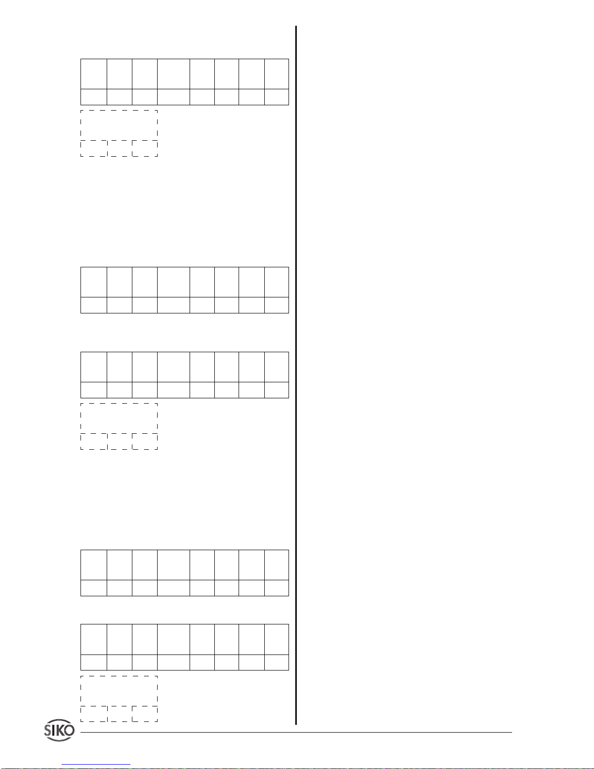
Response:
Number of steps per revolution =
3600
dec
(= 0E10
hex
)
7.7.7 Read IF09-P status parameter
The status of IF09P is mapped to the user data
bytes 1 .. 4. In byte 1 the value 1 represents OK,
and 0 not ready. In byte 2 the number of connected sensors is output (value range 0..31),
Bytes 3 and 4 are assigned 0 .
Example call:
Response:
IF09P ready, 31 SIKONETZ sta-
tions present
7.7.8 Software calibration / reset parameter
Here the addressed sensor is set to the calibration value. The data in the user data bytes 1 .. 4
are irrelevant and can be set to any values.
Example call:
Set SIKONETZ station, addr. 13,
to calibration value
Response:
7.7.9 Display/delete system status parameter (only SIKONETZ3)
The status of the addressed SIKONETZ sta-tion
can be queried or deleted by means of this
parameter. The data bytes are to be interpreted
as follows:
Data byte 1:
Bit 0: Actuator 1 on (only with AP03/1)
Bit 1: Actuator 2 on (only with AP03/1)
Bit 2: Actuator 3 on (only with AP03/1)
Bit 3: position value freezed
Bit 4: keyboard enabled
Bit 5: programming status on
Bit 6: limit comparison active
Bit 7: blocking control active
Data byte 2:
Bit 0: error F01 occurred (display overflow)
Bit 1: error F02 occurred (data transmission
error, CRC error)
Bit 2: error F03 occurred (illegal or unknown
command)
Bit 3: error F05 occurred (illegal value en-
tered)
Bit 4:
Bit 5:
Bit 6:
Bit 7: axle was blocked
Data byte 3:
Bit 0: desired value reached (static)
Bit 1: switch-over point reached (static)
Bit 2: always 0
Bit 3: always 0
Bit 4: lower limit reached (static)
Bit 5: upper limit reached (static)
Bit 6: always 0
Bit 7: ongoing positioning
A set bit (= 1) means active. The bits 0..7 of the
data byte 1 cannot be deleted by the write
request of the command
system status
and are
always up to date. The bits 0..7 (byte2) and 0..7
(byte3) are set automatically; they must, however, be deleted with a write request of the s
ystem
status
command.
Some bits are only present with specific SIKONETZ devices. Please refer to the
SIKONETZ-
Com- Param. Param. Sub-index Data Data Data Data
mand Index Index (=address) byte 1 byte 2 byte 3 byte 4
code Low High
40H 06H 5FH 00H 00H 00H 00H 00H
Com- Param. Param. Sub-index Data Data Data Data
mand Index Index (=address) byte 1 byte 2 byte 3 byte 4
code Low High
42H 05H 5FH 09H 10H 0EH 00H 00H
Position values of the
connected encoders
xxH xxH
Com- Param. Param. Sub-index Data Data Data Data
mand Index Index (=address) byte 1 byte 2 byte 3 byte 4
code Low High
42H 06H 5FH 00H 01H 1FH 00H 00H
Position values of the
connected encoders
xxH xxH
Com- Param. Param. Sub-index Data Data Data Data
mand Index Index (=address) byte 1 byte 2 byte 3 byte 4
code Low High
23H 07H 5FH 0DH 00H 00H 00H 00H
Com- Param. Param. Sub-index Data Data Data Data
mand Index Index (=address) byte 1 byte 2 byte 3 byte 4
code Low High
60H 07H 5FH 0DH 00H 00H 00H 00H
Position values of the
connected encoders
xxH xxH
Page 25
IF09P Datum 07.11.2001 Art.Nr. 79121 Z.Nr. 8666013 Änd.Stand 374/01 2 5
compendium for a detailed description
!
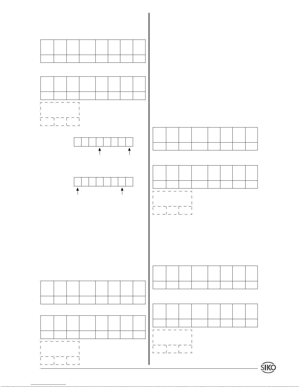
Example call:
Read system status of en-
coder, addr. 7
Response:
Meaning of the data bytes:
Data byte 1:
Data byte 2: no active status messages
Data byte 3:
7.7.10 Read/write desired value
This command is used in connection with positioning jobs. For this, the desired position value
(= desired value) is programmed. Positioning is
initiated by the command
start positioning
described below. The condition for this is, of course,
theuse of the corresponding system design, e.g.
with type AP03/1 SIKONETZ rotary sensor.
Example call:
Read desired value of en-
coder, addr. 6
Response:
Desired value = 25000
dec
(= 61A8
hex
)
7.7.11 Enable keyboard (only SIKONETZ3)
Here, a keyboard can be enabled for devices that
are equipped with a keyboard, on the condition
that a corresponding keyboard was previously
disabled.
The user data bytes 1 .. 4 may contain
any value (indicated in the example by xxH).
This command is
broadcast-
able. By setting of
bit 6 in byte
sub-index
all SIKONETZ stations
can be addressed. If bit 6 is not set, only the
station with the address indicated in byte
Sub-
index
will be accessed. It is, therefore, not
sufficient to set only bit 6 in this byte: a value
corresponding to the address must be entered in
bits 0 .. 5 on principle!
Example call:
The keyboards of all SIKONETZ
stations shall be enabled. (the field
subindex
must contain a value between 01H and 1FH.
Response:
7.7.12 Disable keyboard (only SIKONETZ3)
Command for disabling the keyboard of one or all
SIKONETZ stations, if applicable (broadcastable, see
7.7.11
).
Example call:
Disable keyboard, device address
02H
Response:
Keyboard
enabled
Actuator 1 on
00010001
Ongoing
positioning
switch-over point
reached
10000010
Com- Param. Param. Sub-index Data Data Data Data
mand Index Index ( =ad dress) byte 1 byte 2 byte 3 byte 4
code Low High
40H 08H 5FH 07H 00H 00H 00H 00H
Com- Param. Param. Sub-index Data Data Data Data
mand Index Index (=address) byte 1 byte 2 byte 3 byte 4
code Low High
42H 08H 5FH 07H 11H 00H 82H 00H
Position values of the
connected encoders
xxH xxH
Com- Param. Param. Sub-index Data Data Data Data
mand Index Index (=address) byte 1 byte 2 byte 3 byte 4
code Low High
40H 0AH 5FH 06H 00H 00H 00H 00H
Com- Param. Param. Sub-index Data Data Data Data
mand Index Index (=address) byte 1 byte 2 byte 3 byte 4
code Low High
42H 0AH 5FH 06H A8H 61H 00H 00H
Position values of the
connected encoders
xxH xxH
Com- Param. Param. Sub-index Data Data Data Data
mand Index Index (=address) byte 1 byte 2 byte 3 byte 4
code Low High
23H 0BH 5FH 41H xxH xxH xxH xxH
Com- Param. Param. Sub-index Data Data Data Data
mand Index Index (=address) byte 1 byte 2 byte 3 byte 4
code Low High
60H 0BH 5FH 41H xxH xxH xxH xxH
Position values of the
connected encoders
xxH xxH
Com- Param. Param. Sub-index Data Data Data Data
mand Index Index (=address) byte 1 byte 2 byte 3 byte 4
code Low High
23H 0CH 5FH 02H xxH xxH xxH xxH
Com- Param. Param. Sub-index Data Data Data Data
mand Index Index (=address) byte 1 byte 2 byte 3 byte 4
code Low High
60H 0CH 5FH 02H xxH xxH xxH xxH
Position values of the
connected encoders
xxH xxH
Page 26
2 6 IF09P Datum 07.11.2001 Art.Nr. 79121 Z.Nr. 8666013 Änd.Stand 374/01
7.7.13 Start positioning (only SIKONETZ3)
This command is used in connection with positionable SIKONETZ stations, to drive to a desired position, defined by the above described
command
write desired value
. The contents of
the user data bytes 1 .. 4 are irrelevant.
Example call:
Start positioning, device address
23
dec
(=17H)
Response:
7.7.14 Stop positioning (only SIKONETZ3)
A previously activated positioning procedure is
stopped by this command. The contents of the
user data bytes 1 .. 4 are irrelevant (broadcastable, see
7.7.11
).
Example call:
Stop positioning; all SIKONETZ
devices are accessed, independent of the
address given in the field
sub-index
.
Response:
7.7.15 Enable display (only SIKONETZ3)
Here, the display is enabled in devices with
display. The contents of the user data bytes 1 ..
4 are irrelevant. (broadcast-able, see
7.7.11
)
Example call:
Enable display, all SIKONETZ
devices are accessed, independent of the field
sub-index
.
Response:
7.7.16 Disable display (only SIKONETZ3)
Here the display is disabled in devices with
display. The contents of the user data bytes 1 ..
4 are irrelevant. (broadcast-able, see
7.7.11
).
Example call:
Disable display; all SIKONETZ
devices are accessed, independent of the
address entered in the field
sub-index
.
Response:
7.8 Error codes
In the case of an error (invalid command index,
invalid address, invalid access, e.g. Write Request on Read variable or communication failure between IF09P and the sensors) an error
response is returned instead of a write or read
response, and in the user data bytes the corresponding error number is included.
Com- Data Data Meaning
mand byte 7 byte 8
code
80H 6 6 Wrong index
80H 5 6 Wrong sub-index
(=AP09 or SIKONETZ address)
Com- Param. Param. Sub-index Data Data Data Data
mand Index Index (=address) byte 1 byte 2 byte 3 byte 4
code Low High
23H 0DH 5FH 17H xxH xxH xxH xxH
Com- Param. Param. Sub-index Data Data Data Data
mand Index Index (=address) byte 1 byte 2 byte 3 byte 4
code Low High
60H 0DH 5FH 17H xxH xxH xxH xxH
Position values of the
connected encoders
xxH xxH
Com- Param. Param. Sub-index Data Data Data Data
mand Index Index (=address) byte 1 byte 2 byte 3 byte 4
code Low High
23H 0EH 5FH 41H xxH xxH xxH xxH
Com- Param. Param. Sub-index Data Data Data Data
mand Index Index (=address) byte 1 byte 2 byte 3 byte 4
code Low High
60H 0EH 5FH 41H xxH xxH xxH xxH
Position values of the
connected encoders
xxH xxH
Com- Param. Param. Sub-index Data Data Data Data
mand Index Index (=address) byte 1 byte 2 byte 3 byte 4
code Low High
23H 10H 5FH 41H xxH xxH xxH xxH
Com- Param. Param. Sub-index Data Data Data Data
mand Index Index (=address) byte 1 byte 2 byte 3 byte 4
code Low High
60H 10H 5FH 41H xxH xxH xxH xxH
Position values of the
connected encoders
xxH xxH
Com- Param. Param. Sub-index Data Data Data Data
mand Index Index (=address) byte 1 byte 2 byte 3 byte 4
code Low High
23H 0FH 5FH 41H xxH xxH xxH xxH
Com- Param. Param. Sub-index Data Data Data Data
mand Index Index (=address) byte 1 byte 2 byte 3 byte 4
code Low High
60H 0FH 5FH 41H xxH xxH xxH xxH
Position values of the
connected encoders
xxH xxH
Page 27
IF09P Datum 07.11.2001 Art.Nr. 79121 Z.Nr. 8666013 Änd.Stand 374/01 2 7
80H 3 6 Access rejected, e.g.
Write Request to
Read variable or parameter not present.
80H 4 6 Broadcast not permit-
ted with this command.
80H 1 6 Communication fail-
ure between IF09P
and RS485 bus (connection interrupted or
checksum error)
Example:
Write parameter
display per revo-
lution
on device, addr. > 31
dec
e.g. 72
dec
(=48H)
Response:
Error response, wrong sub-index
(= wrong address)
The error message with code 80H in the
com-
mand code
field persists until the command is
executed with the correct parameters.
Com- Param. Param. Sub-index Data Data Data Data
mand Index Index (=address) byte 1 byte 2 byte 3 byte 4
code Low High
23H 05H 5FH 48H 00H 20H 00H 00H
Com- Param. Param. Sub-index Data Data Data Data
mand Index Index (=address) byte 1 byte 2 byte 3 byte 4
code Low High
80H 05H 5FH 48H 00H 00H 05H 06H
Position values of the
connected encoders
xxH xxH
Page 28

2 8 IF09P Datum 07.11.2001 Art.Nr. 79121 Z.Nr. 8666013 Änd.Stand 374/01
SIKO GmbH
Dr.-Ing. G . Wandres
Werk / Factory:
Weihermattenweg 2
D-79256 Buchenbach
Postanschrift / Postal address:
Postfach 1106
D-79195 Kirchzarten
Telefon / Phone 07661/394-0
Telefax / Fax 07661/394-388
eMail [email protected]
Internet www.siko.de
 Loading...