

Page 1
Benutzerinformation
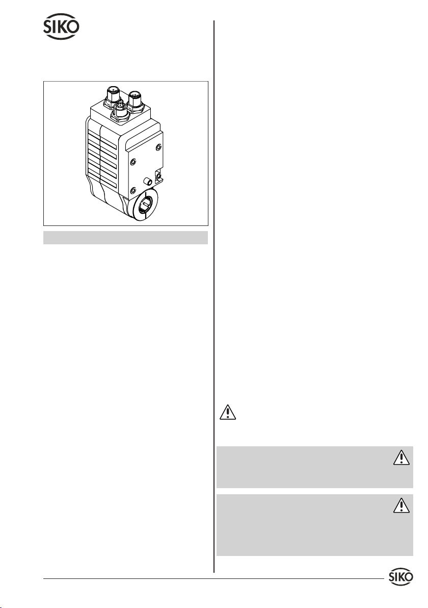
AG03
Getriebe
DEUTSCH
1. Gewährleistungshinweise
Ihr Produkt hat unser Werk in geprüftem und be-
•
triebsbereitem Zustand verlassen. Für den Betrieb
gelten die angegeben Spezifikationen und die
Angaben auf dem Typenschild als Bedingung.
Garantieansprüche gelten nur für Produkte der
•
Firma SIKO GmbH. Bei dem Einsatz in Verbindung
mit Fremdprodukten besteht für das Gesamtsystem
kein Garantieanspruch.
Reparaturen dürfen nur im Werk vorgenommen
•
werden. Für weitere Fragen steht Ihnen die Firma
SIKO GmbH gerne zur Verfügung.
Zur Wahrung Ihrer Gewährleistungsansprüche
•
müssen Sie, vor Montage und Inbetriebnahme,
dieses Dokument sorgfältig durchlesen und alle
Warnungen und Hinweise beachten.
Es ist jede Arbeitsweise zu unterlassen, welche die
•
Sicherheit mit dem Gerät beeinträchtigt.
Die vorgeschriebenen Sicherheitshinweise in
•
dieser Benutzerinformation beachten.
2.2 Montage-, Inbetriebnahme- und Bedien-
personal
Montage, Inbetriebnahme, Bedienung und Wartung darf nur durch qualifiziertes und vom Anlagenbetreiber autorisiertes Personal erfolgen.
2.3 Kennzeichnung von Gefahren und Hinwei-
sen
Sicherheitshinweise bestehen aus dem Signalzeichen und einem Signalwort.
2.3.1 Signalwörter
"Gefahr"
Hinweis auf Gefährdungen die zu schweren Körperverletzungen mit Todesfolge, Sachschäden oder
ungeplanten Gerätereaktionen führen können.
"Warnung"
Hinweis auf Gefährdungen die zu Körperverletzungen, Sachschäden oder ungeplanten Gerätereaktionen führen können.
"Vorsicht"
Hinweis auf Gefährdungen die zu Sachschäden oder
ungeplanten Gerätereaktionen führen können.
"Achtung"
Wichtige Betriebshinweise die die Bedienung erleichtern oder die bei Nichtbeachtung zu ungeplanten Gerätereaktionen führen können.
2.3.2 Signalzeichen
2. Sicherheitshinweise
2.1 Bestimmungsgemäße Verwendung
Der Stellantrieb AG03 dient Verstellaufgaben an
Anlagen und Maschinen im Industriebereich. Der
Stellantrieb darf ausschließlich zu diesen Zwecken
verwendet werden.
Eigenmächtige Umbauten und Veränderungen
•
an dem Gerät sind aus Sicherheitsgründen
verboten.
Die in dieser Benutzerinformation vorgeschrie-
•
benen Betriebs- und Installationsbedingungen
müssen eingehalten werden.
AG03 Datum 23.08.2010 Art.Nr. 83605 Änd. Stand 283/10 1
2.4 Allgemeine Sicherheitshinweise
Gefahr: Verletzungsgefahr durch Verwendung in
explosionsgefährdeten Zonen
Setzen Sie den Antrieb nicht in explosionsgefähr-
•
deten Zonen ein.
Gefahr: Verletzungsgefahr durch ungebremsten
Antrieb
Bei Spannungsausfall, Störungen und Aktionen,
•
die das Freischalten der Endstufe zur Folge
haben, kommt es zum sofortigen Verlust des
Drehmoments.
Page 2
N
S
Stellen Sie sicher, dass diese Gefährdung im
•
Bedarfsfall durch eine externe Haltevorrichtung
(z.B. Haltebremse) verhindert wird.
Warnung: Verletzungsgefahr durch rotierende
Teile
Klemmring und Hohlwelle sind rotierende Teile,
•
von denen Gefährdungen wie Quetschen, Erfassen
und Reibung ausgehen können.
Verhindern Sie die Zugriffsmöglichkeit auf diese
•
Teile durch geeignete Schutzmaßnahmen.
Warnung: Verbrennungsgefahr
Im Betrieb können an der Gehäuseoberfläche
•
Temperaturen >60°C auftreten.
Verhindern Sie die Zugriffsmöglichkeit auf das
•
Gehäuse und schützen Sie temperaturempfindliche Anlagenteile durch geeignete Schutzmaßnahmen.
Vorsicht: Zerstörungsgefahr durch Rückspeisung
Bei hohem Trägheitsmoment beim Abbremsen
•
kann der Antrieb in den generatorischen Betrieb
übergehen. D.h. mechanische Energie wird in
elektrische Energie umgewandelt und ins Versorgungsnetz zurückgespeist.
Das Netzteil muss die dabei entstehende Energie
•
aufnehmen können. Ist dies nicht der Fall, kommt
es zu einer Anhebung der Versorgungsspannung,
die andere Verbraucher an diesem Versorgungsnetz
zerstören kann.
Setzen Sie nur Netzteile mit großer Ausgangskapa-
•
zität (> 10.000µF) bzw. rückspeisefähige Netzteile
ein, damit die überschüssige Energie zwischengespeichert bzw. abgebaut werden kann.
Alternativ bietet sich auch die Verwendung eines
•
entsprechenden Brems-Choppers an.
Vorsicht: Störung durch Fremdmagnete
Schützen Sie den Antrieb vor Einflüssen von
•
Fremdmagneten.
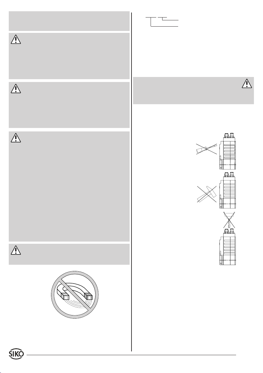
z.B. AG03-0023
Varianten-Nr.
Geräte-Typ
4. Mechanische Montage
Die Montage darf nur gemäß der angegebenen IPSchutzart vorgenommen werden. Das System muss
ggf. zusätzlich gegen schädliche Umwelteinflüsse,
wie z.B. Spritzwasser, Staub, Schläge, Temperatur
geschützt werden.
Warnung: Verlust der Schutzart
Radialdichtringe sind Verschleißteile! Die Schutzart ist deshalb abhängig von Lebensdauer und Zustand der Dichtringe.
Montagehinweise
Gehen Sie sorgfältig mit dem Getriebe um. Folgende Punkte führen unverzüglich zum Verfall der
Garantie:
Zerlegen oder Öffnen des
•
Getriebes (soweit dies nicht
in dieser Benutzerinformation beschrieben wird).
Schläge auf das Getriebe
•
oder die Welle, da dadurch
interne Elemente beschädigt werden können.
Mechanische Bearbeitung
•
am Getriebe (Bohren, Fräsen, usw.). Hierdurch kann
es zu schweren Beschädigungen kommen.
Unzulässige axiale oder
•
radiale Belastung der Welle
oder Überbelastung des
Getriebes.
Unsachgemäße Befesti-
•
gung des Getriebes.
Anbau des Getriebes
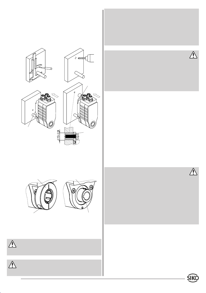
Die Befestigung erfolgt mittels Drehmomentab-
•
stützung (Bolzen oder Lasche siehe Abb. 1) und
Klemmung der Welle. Montieren Sie das Getriebe
möglichst verspannungsfrei und mit einer dafür
vorgesehenen Drehmomentabstützung. Für radiale
spielfreie Montage eignet sich die an der Lasche
befindliche Elastomere-Spannbuchse.
Die Spannbuchse bis zum Anschlag in die
•
3. Identifikation
Das Typenschild zeigt den Gerätetyp mit Variantennummer. Die Lieferpapiere ordnen jeder Variantennummer eine detaillierte Bestellbezeichnung zu.
2 AG03 Datum 23.08.2010 Art.Nr. 83605 Änd. Stand 283/10
Montagebohrung (siehe Abb. 1) schieben und
festziehen.
Kräfte dürfen nicht durch das Gehäuse übertragen
•
werden. Sie dürfen ausschließlich an der Welle
Page 3
0
10
20
30
40 50 60 70 80
0
Litzen sind mit geeigneten Aderendhülsen zu
des Geräts wirken.
Beachten Sie die maximal zul. Wellenbelastungen.
•
Achten Sie auf geringen Winkel und parallelen
•
Versatz zwischen Welle und Anflanschfläche.
Bei nicht korrekter Lage entstehen Spannungen
im Lager, die über erhöhte Erwärmung bis zur
Zerstörung der Lager führen können.
•
versehen.
Vor dem Einschalten sind alle Leitungsanschlüsse
•
und Steckverbindungen zu überprüfen.
Die Betriebsspannung des Gebers muss gemein-
•
sam mit der Folgeelektronik (z.B. Steuerung)
eingeschaltet werden.
Achtung: Störsicherheit
Alle Anschlüsse sind gegen äußere Störeinflüsse
•
geschützt. Der Einsatzort ist aber so zu wählen,
dass induktive oder kapazitive Störungen nicht
auf den Antrieb oder dessen Anschlussleitungen einwirken können!
Durch geeignete Kabelführung und Verdrahtung
Lasche
•
können Störeinflüsse vermindert werden.
Erforderliche Maßnahmen:
Nur geschirmtes Kabel verwenden. Den Kabel-
•
schirm beidseitig auflegen.
Die Verdrahtung von Abschirmung und Masse (0V)
•
muss sternförmig und großflächig erfolgen.
Das System muss in möglichst großem Abstand von
Bolzen
Elastomere
Spannbuchse
•
Leitungen eingebaut werden, die mit Störungen
belastet sind; ggfs. sind zusätzliche Maßnahmen
wie Schirmbleche oder metallisierte Gehäuse
vorzusehen. Leitungsführungen parallel zu Ener-
Abb. 1: Anbaumöglichkeiten (Bohrungsmaße siehe
Produkt-Datenblatt)
Das Antriebsmoment wird über den Klemmring oder
•
die Passfeder (siehe Abb. 2) auf die anzutreibende
Welle übertragen.
Klemmring
Gewindestift
gieleitungen vermeiden.
Schützspulen müssen mit Funkenlöschgliedern
•
beschaltet sein.
Vorsicht: EMV
Um die elektromagnetische Verträglichkeit des
•
AG03 zu gewährleisten, sind folgende Maßnahmen erforderlich (nur bei Geber: Absolut
magnetisch ABM):
Klappferrit (im Lieferumfang) an der Versor-
•
gungsleitung dicht am 4-pol. Steckverbinder
anbringen.
Erdung des Antriebes über den vorgesehenen
Anzugsmoment min. 2,5Nm
(!!!nur mit montierter
Welle zulässig!!!)
Hohlwelle mit Passfedernut nach DIN 6885/1
•
Flachsteckeranschluss mit einem Litzenquerschnitt von min. 4mm².
Abb. 2: Montage Antriebswelle
5. Elektrischer Anschluss
Warnung
Anschlussverbindungen dürfen nicht unter
•
Spannung geschlossen oder gelöst werden!
Spannungsversorgung
Die Versorgung für das AG03 ist ausreichend zu
dimensionieren, da die Stromaufnahme beim Beschleunigen kurzzeitig höher sein kann als der
Nennstrom. Die Spannungswerte sind abhängig
von der Geräteausführung und sind den Lieferpa-
Achtung
Verdrahtungsarbeiten dürfen nur spannungslos
•
pieren oder dem Typenschild zu entnehmen.
erfolgen.
AG03 Datum 23.08.2010 Art.Nr. 83605 Änd. Stand 283/10 3
Page 4
Gefahr: Überlastung
Zur Absicherung des Antriebes ist zusätzlich zur
internen Strombegrenzung eine kundenseitige Sicherung vorzusehen (max. Strombelastung siehe
"Leistungsaufnahme")!
Motorsteuerung +
Endstufe
Inkrementalgeber
OP/LD24
Digitaleingänge +15VDC ... +30VDC; typ. 10mA•
Analogeingänge 0 ... +10VDC; -10VDC ... +10VDC
Rechtslauf+
Linkslauf+
Eil/Schleich+
RechtslaufLinkslaufEil/Schleich-
+24VDC ±10%
•
Litzenquerschnitt min. 0,5mm²
•
Motorsteuerung und Endstufe wer-
•
den gemeinsam über den Anschluss
Motor/Netz versorgt.
+10VDC ... +30VDC
•
Litzenquerschnitt min. 0,14mm²
•
Die Geberelektronik ist galvanisch
•
von der Motorsteuerung + Endstufe
getrennt.
Auflösung: 1024 Imp./Umdr.
•
•
Impedanz >1.3MΩ
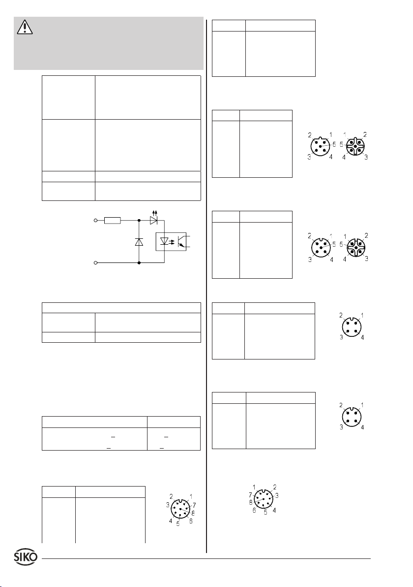
Abb. 3: Eingangsschaltung Digitaleingänge
PIN Belegung
5 Signal B
6 Signal /B
7 Signal 0
8 Signal I
Profibus-DP (PB) Bus-Ein 5-pol. Stiftkontakt, BusAus 5-pol. Buchsenkontakt (absolut magnetisch):
PIN Belegung
1 N.C.
Bus-Ein Bus-Aus
2 BUS A
3 N.C.
4 BUS B
5 N.C.
Ansichtseite = Steckseite
CAN-open Bus-Ein 5-pol. Stiftkontakt, Bus-Aus 5pol. Buchsenkontakt (absolut magnetisch):
PIN Belegung
1 N.C.
Bus-Ein Bus-Aus
2 N.C.
3 CAN_GND
4 CAN_H
5 CAN_L
Ansichtseite = Steckseite
Zulässige Leistungsaufnahme
Motor 50W-M
Motorsteuerung +
Endstufe
Inkrementalgeber <20mA ohne Last•
2,4A Kurzzeitbetrieb S2; 25%ED•
Kurzzeitbetrieb S2 (Auszug aus den Bestimmungen
DIN 57530, VDE 0530, Teil 1)
Betrieb mit konstantem Belastungszustand für begrenzte, festgelegte Zeit (t on) mit anschließender
Pause (t off), bis der Motor die Umgebungstemperatur wieder erreicht hat!
Beispiel: t on off
< 2,5s > 7,5s
< 2,5min > 7,5min
5.1 Anschlussbelegung am Getriebe
Inkrementalgeber 8-pol. Stiftkontakt (OP/LD24):
PIN Belegung
1 +SUB (Sensor)
Motor/Netz 4-pol. Stiftkontakt (inkremental):
PIN Belegung
1 +M / +UB
2 N.C.
3 -M / GND
4 N.C.
Ansichtseite =
Steckseite
Motor/Netz 4-pol. Stiftkontakt (absolut magnetisch):
PIN Belegung
1 +M / +UB
2 Freigabe
3 -M / GND
4 N.C.
Ansichtseite =
Steckseite
Eingänge Motorsteuerung PWM 8-pol. Buchsenkontakt:
Ansichtseite =
Steckseite
2 SGND (Sensor)
3 Signal A
4 Signal /A
4 AG03 Datum 23.08.2010 Art.Nr. 83605 Änd. Stand 283/10
Ansichtseite =
Steckseite
Page 5
PIN Ausführung
Digital
1 Rechtslauf Plus Enable Plus Enable Plus
2 Rechtslauf Masse Enable Masse Enable Masse
3 Linkslauf Plus Rechts/Links Plus N.C.
4 Linkslauf Masse Rechts/Links Masse N.C.
5 Eil/Schleich Plus Analog 0...+10V Analog -10...+10V
6 Eil/Schleich Masse Analog Masse Analog Masse
7+8 N.C. N.C. N.C.
Ausführung
Analog unipolar
Ausführung
Analog bipolar
6. Inbetriebnahme
Bitte beachten Sie die Hinweise auf ordnungsgemäßen mechanischen und elektrischen Anschluss.
Nur dann sind die Voraussetzungen für eine problemlose Inbetriebnahme und einwandfreien Betrieb gegeben.
Prüfen Sie vor der Inbetriebnahme insbesondere
nochmals auf:
korrekte Polung der Betriebsspannung.
•
korrekten Anschluss des Kabels und der Signale.
•
festen Sitz des Getriebes und der Hohlwelle.
•
Warnung: Latchup-Effekte
Die Betriebsspannung des Gerätes muss gemeinsam mit der der Folgeelektronik (z.B. Steuerung)
eingeschaltet werden, um Latchup-Effekte an den
Ausgängen des Gerätes zu vermeiden (nur bei Inkrementalgeber).
eine thermische Abschaltung. Bei Verwendung
sämtlicher Ausgangskanäle darf die Last/Kanal
35mA nicht überschreiten.
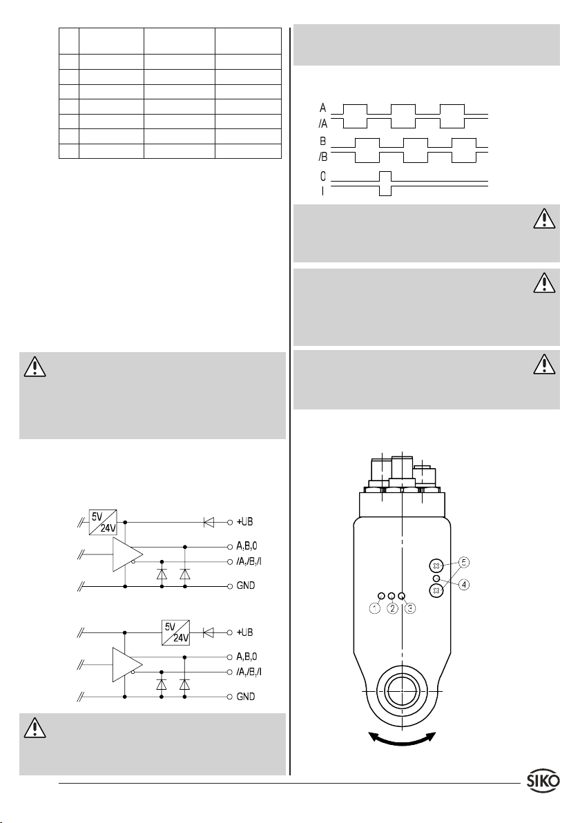
Ausgangssignale / Impulsbild
Achtung
Der Zustand der Signale A und B im Bezug auf das
Referenzsignal 0/I ist nicht definiert und kann von
der Zeichnung abweichen.
Warnung: Impulsfrequenz
Bei der Dimensionierung der Nachfolgeelektronik
ist zu beachten, dass diese für die entsprechende
Impulsfrequenz ausgelegt ist.
max. Impulsfrequenz: 20kHz
Achtung
Es ist zu beachten, dass im Stillstand Impulse mit
der max. Impulsfrequenz (bedingt durch das interne Interpolationsverfahren) auftreten können.
6.2 Motorsteuerung PWM
6.1 Geber Inkremental
Ausgangsschaltung
OP Gegentakt (Push-Pull), differentiell
LED
LD24 Leitungstreiber, differentiell
Vorsicht: LD24
LED:
Rechtslauf = i
Linkslauf = e
Die Geberausgänge entsprechen der Spezifikation
RS422A. Deren Ausgänge können eine Last bis zu
70mA treiben, sind kurzschlussfest und besitzen
AG03 Datum 23.08.2010 Art.Nr. 83605 Änd. Stand 283/10 5
Page 6
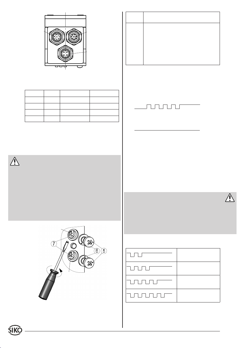
Geber
Motorsteuerung
Motor/Netz
Potenti-
Beschreibung
ometer
P1 Einstellung der Geschwindigkeit im Schnell-
gang; PWM stufenlos 0...100% (linker
Anschlag 0%; rechter Anschlag 100%).
Eingang schnell/langsam aktiv.
P2 Einstellung der Geschwindigkeit im
Schleichgang; PWM stufenlos 0...100% (linker Anschlag 0%; rechter Anschlag 100%).
Eingang schnell/langsam inaktiv.
Abb. 4: Motorsteuerung PWM
Anzeigen:
LED Digital Analog unipolar Analog bipolar
1, orange Eilgang keine Funktion keine Funktion
2, orange Links Rechts keine Funktion
3, orange Rechts Enable Enable
4, grün Status Status Status
Nur bei Ausf. mit digitaler Motorsteuerung:
Durch öffnen der Kreuzschlitzschrauben (5) (siehe
Abb. 4+5) gelangt man zu den stufenlos einstellbaren Trimmpotentiometern.
Warnung
Schutzartbedingt dürfen lediglich die Kreuzschlitz-
•
schrauben (5) gelöst werden (siehe Abb. 5).
Bei gelösten Schrauben (5) des Verschlussde-
•
ckels ist die Schutzart des AG03 nicht mehr
gewährleistet.
Parameter an den Trimmpotentiometern (7), mit-
•
tels 2mm Schlitzschraubendreher einstellen.
Bei Wiedermontage der Schrauben (5) auf korrek-
•
ten Sitz der Dichtungen (6) achten!
P1
P2
Abb. 5: Parametereinstellung
6.3 Betriebszustände
Betriebs- und Fehlerzustände der AG03 Steuerung
werden über die grüne Status LED (4) signalisiert.
Startup: 5x blinken innerhalb von 1s.1.
Ein
Aus
Betrieb o.K.: Dauerleuchten.2.
Ein
Aus
6.4 Überwachungsfunktionen
Um den Motor und die Endstufe im laufenden Betrieb vor Zerstörung zu schützen, werden im AG03
folgende Parameter überwacht:
Endstufentemperatur
•
Laststrom
•
Versorgungsspannung
•
Gefahr
Erreicht ein überwachter Parameter kritische Werte, so wird die Endstufe abgeschaltet was zum sofortigen Verlust des Drehmomentes führt. Über die
Status-LED (4) wird gleichzeitig ein Fehlerblinkmuster ausgegeben, über das der eingetretene
Fehler identifiziert werden kann.
Fehlerblinkmuster
Ein
Übertemperatur Endstufe
(2x blinken)
Aus
Ein
Überlastung des Antriebs
(3x blinken)
Aus
Ein
Überspannung Zwischenkreis (4x blinken)
Aus
Ein
Unterspannung
(5x blinken)
Aus
6 AG03 Datum 23.08.2010 Art.Nr. 83605 Änd. Stand 283/10
Page 7
Fehlerzustand zurücksetzen
Achtung
Wird beim Einschalten des Gerätes bereits eine
Überspannung festgestellt, so kann der Fehlerzustand nur durch Ausschalten der Versorgung zurückgesetzt werden.
Fehlereintritt bei aktiven Steuereingängen:
Das AG03 bleibt statisch im Fehlerzustand, bis
dieser vom Benutzer zurückgesetzt wird. Damit
wird ein unkontrolliertes Wiederanlaufen des Motors unterbunden.
Ein Fehlerzustand kann bei aktiven Steuereingängen ohne Ausschalten des Gerätes wie folgt zurückgesetzt werden:
Steuerungsvariante Digital: Eingänge links +
•
rechts zurücksetzen.
Steuerungsvariante Analog unipolar / Analog
•
bipolar: Enable-Eingang zurücksetzen.
Fehlereintritt bei inaktiven Steuereingängen:
Das AG03 befindet sich nur solange im Fehlerzustand, wie auch der Fehler vorhanden ist.
6.5 Geber absolut magnetisch ABM
DIP-Schalter
Rechtslauf
LED
Linkslauf
LED
CAN-openProfibus
ErdungMotor/Netz
Bus-AusBus-Ein
ErdungMotor/Netz
Bus-AusBus-Ein
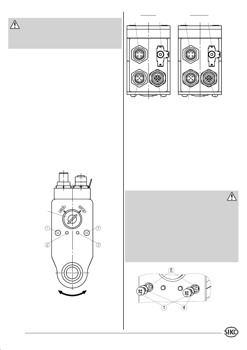
Abb. 6: Geber absolut
Nach ordnungsgemäßer Montage und Verdrahtung kann das AG03 durch Einschalten der 24V
Versorgung in Betrieb genommen werden. Grünes
Leuchten der Status-LED (2) signalisiert, dass der
Freigabeeingang aktiv und der Antrieb betriebsbereit ist.
Die verschiedenen Betriebszustände der Bus-LED
(3) sind dem Handbuch zu entnehmen.
6.5.1 Tipptastenbetrieb
Durch öffnen der Kreuzschlitzschrauben (1) (siehe
Abb. 6+7) gelangt man zu den Tipptasten.
Warnung: Verlust der Schutzart
Schutzartbedingt dürfen lediglich die Kreuzschlitz-
•
schrauben (1) gelöst werden (siehe Abb. 7).
Bei gelösten Schrauben (1) des Verschlussde-
•
ckels ist die Schutzart des AG03 nicht mehr
gewährleistet.
Durch Betätigen der Tasten (5) wird zwischen
•
Rechtslauf oder Linkslauf umgeschaltet (detaillierte Beschreibung siehe Handbuch).
Bei Wiedermontage der Schrauben (1) auf korrek-
•
ten Sitz der Dichtungen (4) achten!
Rechtslauf = i
Linkslauf = e
Abb. 7: Tipptasten
AG03 Datum 23.08.2010 Art.Nr. 83605 Änd. Stand 283/10 7
Page 8
Achtung
Die Drehrichtung im Tipptastenbetrieb ist vom
•
Parameter "Drehrichtung" unabhängig.
Der Tipptastenbetrieb ist nur im Positioniermodus
•
verfügbar.
PROFIBUS: Der Tipptastenbetrieb ist nur verfügbar,
•
wenn sich der Profibus Zustandsautomat nicht im
Zustand Data Exchange befindet.
CAN-open: Der Tipptastenbetrieb ist im NMT
•
– Zustand "OPERATIONAL" und "STOPPED" nicht
verfügbar.
SW1
SW2
SW3
SW4
SW5
SW6
SW7
[20]
[21]
[22]
[23]
[24]
[25]
OFF OFF ON ON ON ON ON 124
ON OFF ON ON ON ON ON 125
OFF ON ON ON ON ON ON 126
ON ON ON ON ON ON ON 126!
[26]
eingestellte
Slave-Adresse
Achtung
Die DIP - Schaltereinstellungen werden nur beim
Einschalten der Versorgungsspannung eingelesen.
Eine Änderung der Slave - Adresse während des
Betriebs hat keine Auswirkungen.
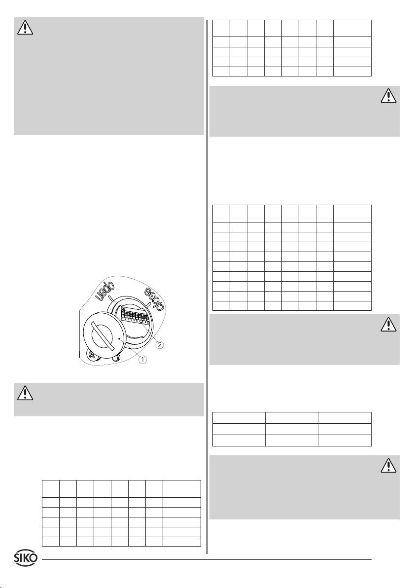
6.5.2 Zugang DIP-Schalter (Abb. 8)
Verschlussdeckel (1) gegen den Uhrzeigersinn,
1.
mittels Schraubendreher, bis zur Markierung
"open" drehen.
Schraubendreher am Umfang des Verschlussde-
2.
ckels (1) ansetzen und axial heraushebeln.
Adresse am DIP-Schalter (2) einstellen.
3.
Bei Wiedermontage des Deckels auf korrekten
4.
Sitz der Dichtung achten und Deckelschlitz auf
Markierung "open" ausrichten.
Verschlussdeckel mit leichtem axialen Druck bis
5.
zu Markierung "close" drehen.
Abb. 8: Adresseinstellung
Achtung
Ein Überdrehen des Deckels, außerhalb des markierten Bereiches, führt zum Verlust der Schutzart.
6.5.3 Adresseinstellung Profibus
Die Eingabe der Slave - Adresse erfolgt über die Schalter 1 - 7 im Binärformat. Die Einstellung der Adresse
127 wird intern in die Adresse 126 umgesetzt.
Folgende Tabelle verdeutlicht dies:
SW1
SW2
SW3
SW4
SW5
SW6
SW7
[20]
[21]
[22]
[23]
[24]
[25]
OFF OFF OFF OFF OFF OFF OFF 0
ON OFF OFF OFF OFF OFF OFF 1
OFF ON OFF OFF OFF OFF OFF 2
ON ON OFF OFF OFF OFF OFF 3
..
..
..
..
..
..
[26]
..
eingestellte
Slave-Adresse
..
6.5.4 Adresseinstellung CAN-open
Die Eingabe der Knotenadresse erfolgt über die
Schalter 1 - 7 im Binärformat. Die Einstellung der
Adresse 0 wird intern in die Adresse 1 umgesetzt.
Folgende Tabelle verdeutlicht dies:
SW1
SW2
SW3
SW4
SW5
SW6
SW7
[20]
[21]
[22]
[23]
[24]
[25]
OFF OFF OFF OFF OFF OFF OFF 1!
ON OFF OFF OFF OFF OFF OFF 1
OFF ON OFF OFF OFF OFF OFF 2
ON ON OFF OFF OFF OFF OFF 3
..
..
..
..
..
..
OFF OFF ON ON ON ON ON 124
ON OFF ON ON ON ON ON 125
OFF ON ON ON ON ON ON 126
ON ON ON ON ON ON ON 127
[26]
..
eingestellte
Slave-Adresse
..
Achtung
Die DIP - Schaltereinstellungen werden nur beim
Einschalten der Versorgungsspannung eingelesen.
Eine Änderung der Knotenadresse während des Betriebs hat keine Auswirkungen.
6.5.5 Busabschluss
Über die DIP - Schalter 9 + 10 kann der interne
Busabschluss aktiviert werden:
SW9 SW10 Busabschluss
OFF OFF deaktiviert
ON ON aktiv
Achtung
Es ist zu beachten, dass immer beide DIP-Schalter
•
für die korrekte Funktion der Busterminierung
notwendig sind.
Die Unterbrechung der AG03-Versorgungsspan-
•
nung führt zu Busterminierungs-Störungen!
8 AG03 Datum 23.08.2010 Art.Nr. 83605 Änd. Stand 283/10
Page 9
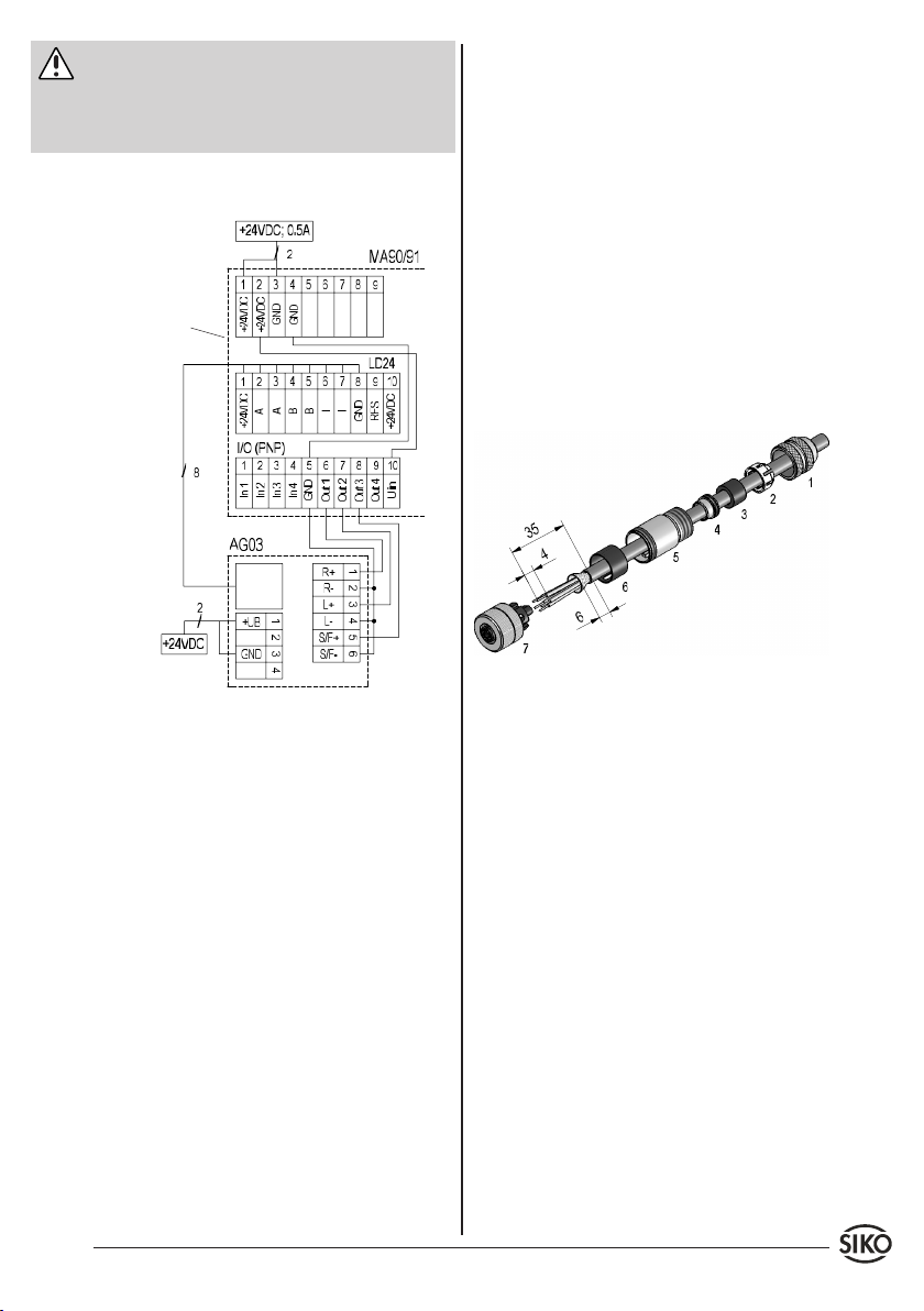
Warnung
Vor Inbetriebnahme des Antriebes die Handbü-
cher sorgfälltig durchlesen. Die Handbücher für
Profibus-DP und CANopen sind der beigefügten
CD zu entnehmen.
Applikationsbeispiel Motorsteuerung PWM, AG03
(nur Digital) -> MA90 (I/O PNP)
Versorgung
Versorgung
Geber
Geber
Bei SIKO als Zubehör unter Art.Nr. 84732 (CAN-open
AUS 5-pol.) erhältlich. Litzenquerschnitt der Leitungen max. 0,75mm². Kabeldurchlass: 6-8mm.
Bei der Stecker-Montage gehen Sie bitte schrittweise vor (Abb. 9):
Dichtung an Schirmring (4) montieren.
1.
Teile 1 ... 6 über Kabelmantel schieben.
2.
Kabel abmanteln, Leiter abisolieren.
3.
Schirm kürzen und umlegen.
4.
Litzen in Einsatz (7) klemmen (entspr. An-
5.
schlussplan).
Teile 2 ... 6 montieren. Schirm wird um Schirm-
6.
ring (4) gelegt.
Druckschraube (1) mit Kupplunghülse (5)
7.
verschrauben.
Versorgung
7. Zubehör Anschluss-Stecker
Gegenstecker gerade
Bei SIKO als Zubehör unter Art.Nr. 83526 (Motor/
Netz 4-pol.) erhältlich. Litzenquerschnitt der Lei-
tungen max. 0,75mm². Kabeldurchlass: 6-8mm.
Bei SIKO als Zubehör unter Art.Nr. 83527 (Eingänge
PWM 8-pol.) erhältlich. Litzenquerschnitt der Leitungen max. 0,5mm². Kabeldurchlass: 6-8mm.
Bei SIKO als Zubehör unter Art.Nr. 83525 (Inkremen-
talgeber 8-pol.) erhältlich. Litzenquerschnitt der
Leitungen max. 0,5mm². Kabeldurchlass: 6-8mm.
Bei SIKO als Zubehör unter Art.Nr. 83991 (Profibus
EIN 5-pol.) erhältlich. Litzenquerschnitt der Leitungen max. 0,75mm². Kabeldurchlass: 6-8mm.
Bei SIKO als Zubehör unter Art.Nr. 83992 (Profibus
AUS 5-pol.) erhältlich. Litzenquerschnitt der Leitungen max. 0,75mm². Kabeldurchlass: 6-8mm.
Bei SIKO als Zubehör unter Art.Nr. 84109 (CAN-open
EIN 5-pol.) erhältlich. Litzenquerschnitt der Leitungen max. 0,75mm². Kabeldurchlass: 6-8mm.
AG03 Datum 23.08.2010 Art.Nr. 83605 Änd. Stand 283/10 9
Abb. 9: Gegenstecker gerade
Gegenstecker gewinkelt (5-pol.)
Bei SIKO als Zubehör unter Art.Nr. 82804 (Profibus
EIN 5-pol.) erhältlich. Litzenquerschnitt der Lei-
tungen min. 0,14mm²; max. 0,5mm². Kabeldurchlass: 4-8mm.
Bei SIKO als Zubehör unter Art.Nr. 82805 (Profibus
AUS 5-pol.) erhältlich. Litzenquerschnitt der Leitungen min. 0,14mm²; max. 0,5mm². Kabeldurchlass: 4-8mm.
Bei SIKO als Zubehör unter Art.Nr. 83006 (CAN-
open EIN 5-pol.) erhältlich. Litzenquerschnitt der
Leitungen min. 0,14mm²; max. 0,5mm². Kabeldurchlass: 4-8mm.
Bei SIKO als Zubehör unter Art.Nr. 83007 (CAN-
open AUS 5-pol.) erhältlich. Litzenquerschnitt der
Leitungen min. 0,14mm²; max. 0,5mm². Kabeldurchlass: 4-8mm.
Bei der Stecker-Montage gehen Sie bitte schrittweise vor (Abb. 10):
Druckmutter auf das Kabel fädeln.
1.
Kabel abmanteln, Schirm kürzen.
2.
Adern abisolieren
3.
Page 10
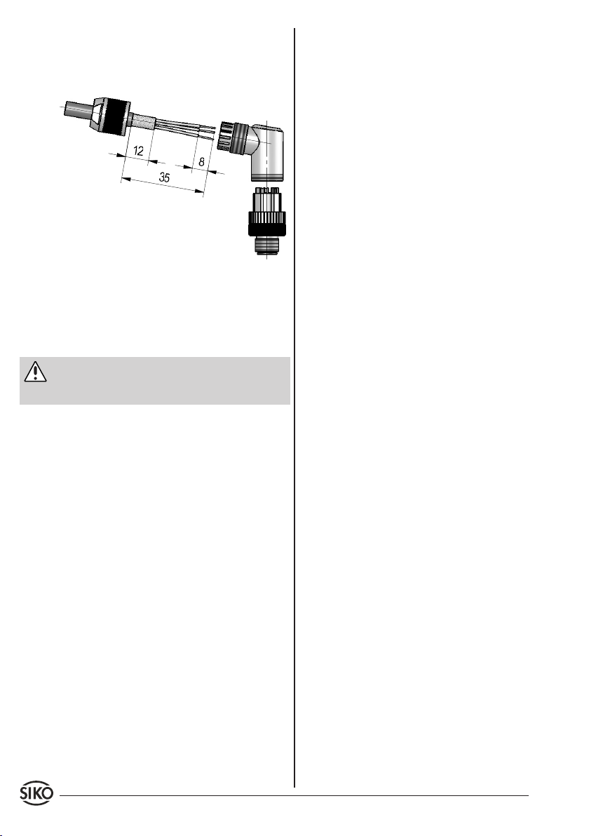
Adern durch das Gehäuse fädeln und anschlie-
4.
ßen.
Gehäuse auf Steckerkorper schrauben.
5.
Druckmutter anziehen.
6.
Abb. 10: Gegenstecker gewinkelt
Ändern der Winkelstellung (Abb. 10):
Buchseneinsatz aufdrehen, leicht herausziehen
1.
und in gewünschte Winkelstellung (45° Schritte)
verdrehen.
Buchseneinsatz aufschrauben.
2.
Achtung
Mehrfache Winkelverstellungen in eine Richtung,
führen zu Leitungsverkürzung und Unterbrechung.
10 AG03 Datum 23.08.2010 Art.Nr. 83605 Änd. Stand 283/10
Page 11
User Information
AG03
Gear
ENGLISH
1. Warranty information
Your device has been quality controlled, tested
•
and is ready for use. Please observe all warnings
and information which are marked either directly
on the device or specified in this document.
Warranty can only be claimed for components
•
supplied by SIKO GmbH. If the system is used
together with other products, there is no warranty
for the complete system.
Repairs should be carried out only at our works.
•
If any information is missing or unclear, please
contact the SIKO sales staff.
For preservation of your warranty claims you must
•
read and understand this document fully prior to
mounting and commissioning the AG03 actuator
and observe all warnings and hints.
2. Safety information
2.1 Intended use
The actuator AG03 is intended for adjustment
tasks on equipment and machinery for industrial applications and must never be used for other
purposes.
Conversion or alteration of the device not approved
•
by SIKO is forbidden for safety reasons.
Observe the operation and installation instructions
•
specified in this User Information.
Refrain from any operation that may compromise
•
safety with the device.
Observe the prescribed safety information con-
•
tained in this user information.
2.2 Mounting, commissioning and operating
staff
Mounting, commissioning, operating and maintenance must only be performed by expert personnel
authorized by the plant operator.
2.3 Identification of dangers and notes
Safety notes consist of a signal sign and a signal
word.
2.3.1 Signal words
"Danger"
Indication of dangers that may cause grievous bodily harm resulting in death, property damage or
unplanned reactions of devices.
"Warning"
Indication of dangers that may be capable of causing bodily harm, property damage or unplanned
reactions of devices.
"Caution"
Indication of dangers that may be capable of causing property damage or unplanned reactions of
devices.
"Attention"
Important notes that facilitate operation or are
capable of causing property damage or unplanned
reactions of devices if not complied with.
2.3.2 Signal signs
2.4 General safety notes
Danger: Danger of injury when used in hazardous areas
Do not use the actuator in hazardous areas.
•
Danger: Danger of injury by unbraked drive
Power failure, faults and actions resulting in the
•
activation of the output stage cause immediate
loss of torque.
Make sure that this danger will be prevented
•
by means of an external fixture (e.g. holding
brake) if required.
AG03 Datum 23.08.2010 Art.Nr. 83605 Änd. Stand 283/10 11
Page 12
N
S
Warning: Danger of injury by rotating parts
Clamping ring and hollow shaft are rotating parts
•
capable of causing hazards including bruises,
friction or catching.
Install appropriate guards to prevent persons from
•
accessing such parts.
Warning: Danger of burning
During operation, temperatures >60°C may de-
•
velop on the surface of the housing .
Install appropriate guards to prevent persons from
•
accessing the housing and protect temperaturesensitive parts of the equipment.
Caution: Danger of destruction by energy recovery
With high torque of inertia during braking, the
•
drive can switch over to generator operation; i.e.
mechanical is transformed into electrical energy
and fed back into the mains power supply.
This requires the power supply unit to be able
•
to take up the enery being generated. Otherwise,
voltage will increase and may destroy other appliances in the same power supply network.
Use only power supply units with a high output
•
capacitance (> 10.000µF) or power supply units
suitable for energy recovery so that excess energy
can be buffered or consumed.
Alternately, a suitable brake chopper may be
•
used.
Caution: Interference by external magnets
Protect the drive from the influences of external
•
magnets.
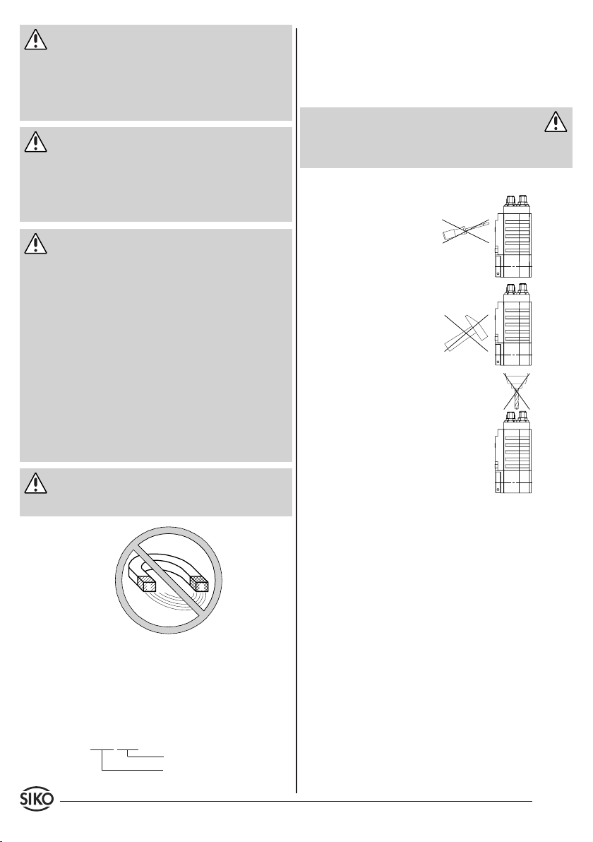
4. Installation
For mounting, the degree of protection specified
must be observed. If necessary, protect the unit
against environmental influences such as sprayed
water, dust, knocks, extreme temperatures.
Warning: Loss of the type of protection
Radial shaft sealings are subject to wear! Protection class therefore depends on life and condition
of sealings.
Mounting instructions
Please handle the gear carefully.
Especially do not:
disassemble or open the
•
gear (unless stipulated in
this brochure).
knock on casing or shaft;
•
the gear's inner components
could be damaged.
mechanically work on the
•
gear (drilling, milling, etc.),
which would cause serious
damage.
apply inadmissible axial or
•
radial load on the shaft or
overload the gear.
mount the gear incorrectly.
•
Otherwise manufacturer's warranty will be invalidated!
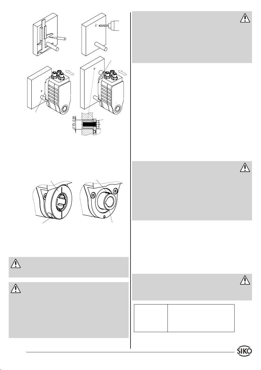
Mounting of the gear
Mounting is via torque bracing (pin or bracket,
•
see fig. 1) and clamping of the shaft. Mount the
gear with as little tension as possible using the
specified torque bracing. In order to achieve
backlash-free radial fixation, we recommend to
use the elastomer clamp bushing on the mounting bracket.
Entirely slide the spring collet into the mounting
•
bore (see fig. 1) and then tighten it.
Forces must not be transmitted via the housing,
3. Identification
Please check the particular type of unit and type
number from the identification plate. Type number
and the corresponding version are indicated in the
delivery documentation.
e.g. AG03-0023
version number
type of unit
12 AG03 Datum 23.08.2010 Art.Nr. 83605 Änd. Stand 283/10
•
but only via the shaft.
Do not exceed the values for the maximum axial
•
and radial shaft load.
Take care that there is no large angle and that
•
there is a parallel offset between shaft and flanging on surface. In case of incorrect positioning
tensions develop in the bearing that may lead
to increased heating and thus to destruction of
the bearings.
Page 13
0
10
20
30
40 50 60 70 80
0
pin
Fig. 1: Mounting options (for the bore dimensions
see the Product data sheet)
Via the clamping ring or keyway (see fig. 2) the
•
driving torque is transferred onto the driving
shaft.
clamping ring
Starting torque = 2,5Nm min.
(!!!only admissable with
mounted shaft!!!)
grub screw
Hollow shaft with
keyway DIN 6885/1
Fig. 2: Driving shaft mounting
5. Electrical connection
Warning
Switch power off before any plug is inserted
•
or removed!
Attention
Wiring must only be carried out with power off.
•
Provide stranded wires with ferrules.
•
Check all lines and connections before switching
•
on the equipment.
The gear's and follower electronic's (e.g. control
•
unit) operating supply must be switched on
simultaneously.
bracket
elastomer
clamp bushing
Attention: Interference resistance
All connections are protected against the effects
•
of interference. The location should be selec-
ted to ensure that no capacitive or inductive
interferences can affect the encoder or the
connection lines!
Suitable wiring layout and choice of cable can
•
minimise the effects of interference.
Necessary measures:
Only screened cable should be used. Screen should
•
be connected to earth at both ends.
Wiring to screen and to ground (0V) must be via
•
a good earth point having a large surface area
for minimum impedance.
The unit should be positioned well away from
•
cables with interference; if necessary a protective
screen or metal housing must be provided. The
running of wiring parallel to the mains supply
should be avoided.
Contactor coils must be linked with spark sup-
•
pression.
Caution: EMC
Following actions are needed to guarantee
•
AG03's electromagnetic compatibility (only
for encoder: magnetic absolute ABM):
The retractable ferrite (supplied with the AG03)
•
is to be attached to the supply line near the
4-pole connector.
The drive is to earthed via the flat connection
•
with a strand section of at least 4mm².
Power supply
The supply of the AG03 should be adequately
dimensioned since power consumption during
acceleration may be transiently higher than the
nominal current. Supply voltage depends on the
unit type and is indicated in the delivery documentation and on the identification plate.
Danger: Overload
For fusing the drive, the customer must provide
a fuse in addition to internal current limitation
(max. current load - see "Power consumption")!
Motor control +
output stage
+24VDC ±10%
•
Wire cross section min. 0,5mm²
•
Motor control and output stage are
•
both supplied via the motor/mains
connection.
AG03 Datum 23.08.2010 Art.Nr. 83605 Änd. Stand 283/10 13
Page 14
Incremental encoder OP/LD24
Digital inputs +15VDC ... +30VDC; typ. 10mA•
Analogue inputs 0 ... +10VDC; -10VDC ... +10VDC
right motion+
left motion+
fast/creep mation+
right motionleft motionfast/creep mation-
+10VDC ... +30VDC
•
Wire cross section min. 0,14mm²
•
The encoder electronics unit is
•
galvanically isolated from motor
control and output stage.
Resolution: 1024 pulses/rev.
•
•
impedance >1.3MΩ
Fig. 3: Input circuit/digital inputs
Power consumption
Motor 50W-M
Motor control +
output stage
Incremental encoder <20mA without load•
2,4A short-time operation S2;
•
25%ED
Short time operation S2 (Extract from provisions
DIN 57530, VDE 0530, part 1)
Operation with constant loading state for a defined limited time (t on) with subsequent pause (t
off), until the motor has regained ambient temperature!
Example: t on off
< 2,5s > 7,5s
< 2,5min > 7,5min
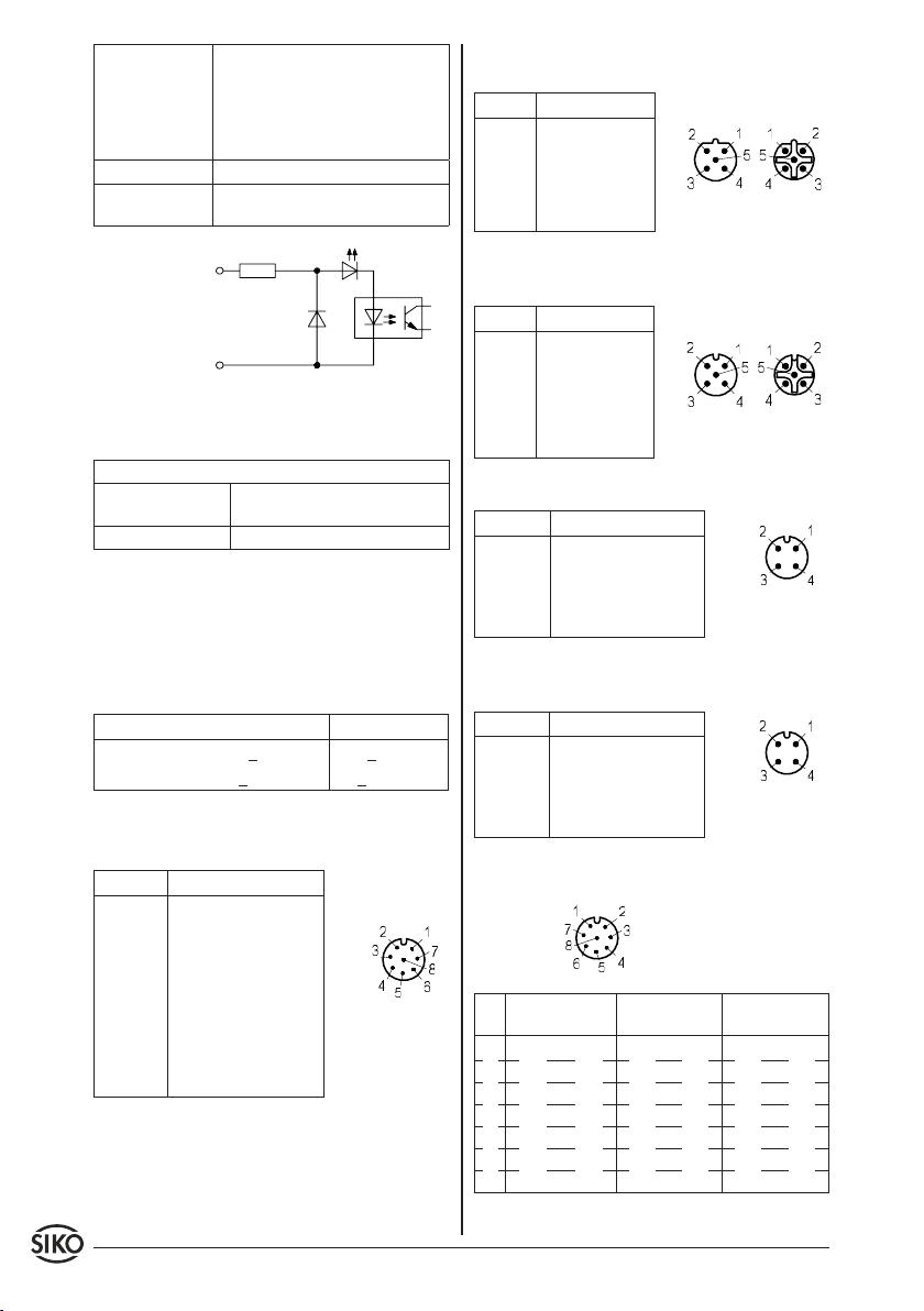
5.1 Pin assignment on the gear
Incremental encoder 8 pole plug pin (OP/LD24):
PIN Designation
1 +SUB (Sensor)
2 SGND (Sensor)
3 Signal A
4 Signal /A
5 Signal B
6 Signal /B
viewing side =
plug-in side
7 Signal 0
8 Signal I
Profibus-DP (PB) Bus In 5 pole plug pin, Bus Out
5 pole socket contact (absolute magnetic):
PIN Designation
1 N.C.
Bus In Bus Out
2 BUS A
3 N.C.
4 BUS B
5 N.C.
viewing side = plug-in side
CAN-open Bus In 5 pole plug pin, Bus Out 5 pole
socket contact (absolute magnetic):
PIN Belegung
1 N.C.
Bus In Bus Out
2 N.C.
3 CAN_GND
4 CAN_H
viewing side = plug-in side
5 CAN_L
Motor/network 4 pole plug pin (incremental):
PIN Designation
1 +M / +UB
2 N.C.
3 -M / GND
viewing side =
plug-in side
4 N.C.
Motor/network 4 pole plug pin (absolute magnetic):
PIN Designation
1 +M / +UB
2 Enable
3 -M / GND
viewing side =
plug-in side
4 N.C.
Motor control inputs PWM 8 pole socket contact:
viewing side =
plug-in side
PIN Version digital Version ana-
logue unipolar
1 right motion plus enable plus enable plus
2 right motion ground enable ground enable ground
3 left motion plus right/left plus N.C.
4 left motion ground right/left ground N.C.
5 fast/creep motion analogue 0...+10V analogue -10...+10V
6 fast/creep motion analogue ground analogue ground
7+8 N.C. N.C. N.C.
Version analogue bipolar
14 AG03 Datum 23.08.2010 Art.Nr. 83605 Änd. Stand 283/10
Page 15
6. Commissioning
Please carefully read the information on the gear's
mechanical and electrical connection. This will
ensure a trouble free commissioning and operation.
Before operation, please check again:
that the supply voltage's polarity is correct.
•
correct connection of cable and signal lines
•
secure gear fixation on the hollow shaft.
•
correct mounting and functioning of the limit
•
switches.
Warning: latch-up effects
The unit's and follower electronic's (e.g. control
unit) operating supply must be switched on simultaneoulsy to avoid latch-up effects on the unit's
outputs (only by incremental encoder).
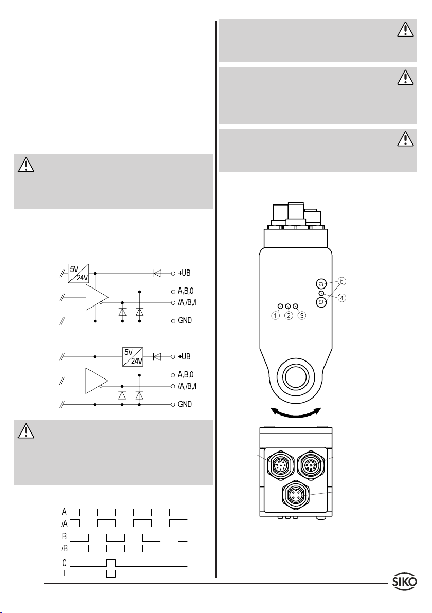
6.1 Incremental encoder
Output circuits
OP (Push-Pull), differential
Attention
The states of signals A and B with regard to the
reference signal O/I are not defined and can deviate from the drawing.
Warning: pulse frequency
When dimensioning the downstream electronics
units take care that it is designed for the appropriate pulse frequency.
max. pulse frequency: 20kHz
Attention
Please not that pulses with the max. pulse frequency may occur during standstill of the device
(due to the internal interpolation method).
6.2 Motor control PWM
LED
LED:
LD24 Line Driver, differential
right motion = i
left motion = e
Caution: LD24
The encoder outputs correspond to RS422A. Its
outputs can drive a load of up to 70mA, are shortcircuit-proofed and have a thermic de-energizati-
Encoder
Motor control
on. The load per channel must not exceed 35mA
by using all channels.
Output signals / Wave form
Motor/network
Fig. 4: Motor control PWM
AG03 Datum 23.08.2010 Art.Nr. 83605 Änd. Stand 283/10 15
Page 16
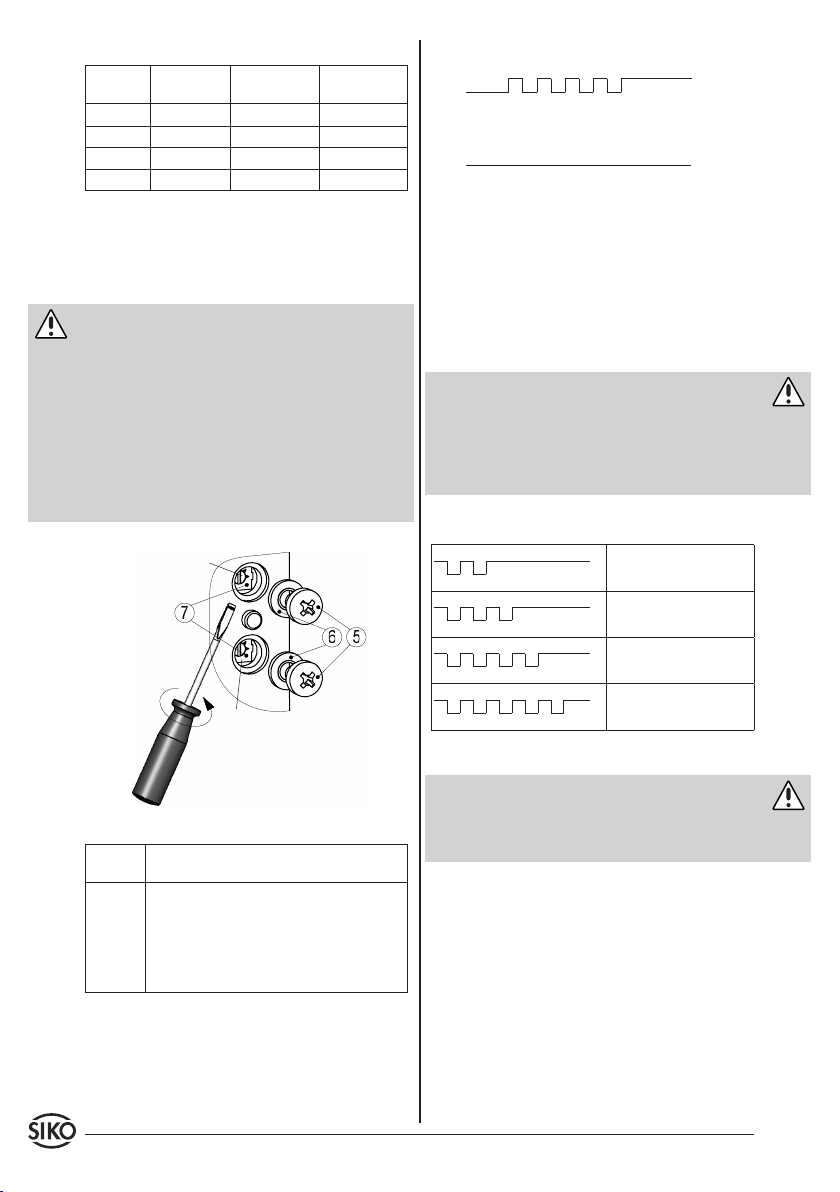
Displays:
LED Digital Analogue
unipolar
1, orange fast traverse no function no function
2, orange left right no function
3, orange right enable enable
4, green status status status
Analogue
bipolar
Only for digital motor control version:
By opening the Phillips screws (5) (see fig. 4+5)
the continuously adjustable trim potentiometer
can be accessed.
Warning
Due to the type of protection, only the crosshead
•
screws may be loosened (see fig. 5).
With the screws (5) of the cover loosened the type
•
of protection of AG03 is no longer guaranteed.
Set the parameters on the trimming potentiome-
•
ters (7) using a 2mm slot screwdriver.
When remounting the screws (5) take care that
•
the seals (6) are seated correctly!
P1
P2
Start-up: 5x blinking within 1s.1.
on
off
Operation o.k.: permanent glowing.2.
on
off
6.4 Monitoring functions
In order to protect motor and output stage from
destruction during ongoing operation, the following parameters are monitored in the AG03:
output stage temperature
•
load current
•
supply voltage
•
Danger
If a monitored parameter reaches critical values,
the output stage will tur turned off resulting in
immediate loss of torque. Simultaneously, an error
blinking pattern is output via the status LED (4)
that allows identification of the pending error.
Error blinking pattern
on
overtemperature output
stage (2x blinking)
off
on
Drive overload
(3x blinking)
off
on
Overvoltage of intermediate circuit (4x blinking)
off
on
Undervoltage
(5x blinking)
off
Resetting the error state
Attention
Fig. 5: Parameter setting
Potenti-
Description
ometer
P1 Speed setting in fast motion; PWM conti-
nuously adjustable 0 to 100% (left stop 0%;
right stop 100%). Active fast/slow input.
P2 Speed setting in fast motion; PWM conti-
nuously adjustable 0 to 100% (left stop 0%;
right stop 100%). Inactive fast/slow input.
If overvoltage is already detected when switching
on the device, the error state can be reset by switching off power supply only.
Error occurrence with active control inputs:
In order to prevent the motor from uncontrolled
restart the AG03 remains statically in the error
state until it is reset by the user.
An error state with active control inputs can be
reset without switching off the device as follows:
6.3 Operational modes
Operational and error states of the AG03 control
are signalled via the green status LED (4).
Digital control version: reset inputs left +
•
right.
Analogue unipolar / analogue bipolar control
•
version: reset enable input.
16 AG03 Datum 23.08.2010 Art.Nr. 83605 Änd. Stand 283/10
Page 17
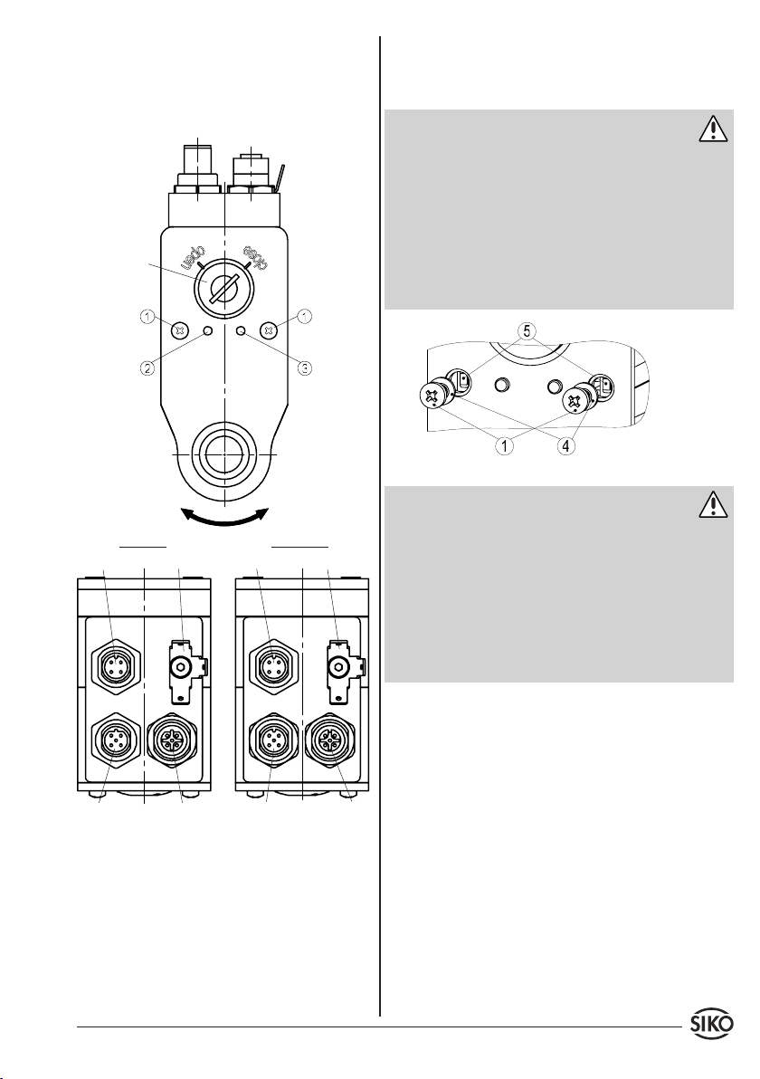
Error occurrence with inactive control inputs:
The AG03 is in the error state only as long as the
error is pending.
6.5.1 Inching operation
By opening the cross-head screws, (1) (see fig.
6+7) the inching buttons can be accessed.
6.5 Magnetic absolute encoder ABM
DIP switch
right motion
LED
right motion = i
left motion = e
CAN-openProfibus
EarthingMotor/network
left motion
LED
EarthingMotor/network
Warning: Loss of the type of protection
Due to the type of protection, only the crosshead
•
screws (1) may be loosened (see fig. 7).
With the screws (1) of the cover loosened the type
•
of protection of AG03 is no longer guaranteed.
By pressing the buttons (5), left-hand or right-
•
hand motion can be selected (refer to the manual
for a detailed description).
When remounting the screws (1) take care that
•
the seals (4) are seated correctly!
Fig. 7: Inching operation
Attention
The sense of rotation in inching operation is inde-
•
pendent from the "Sense of rotation" parameter.
Inching operation is available in positioning
•
mode only.
PROFIBUS: Inching operation is only enabled if
•
the Profibus State machine is not in the Data
Exchange state.
CAN-open: Touch button operation is unavailable
•
for NMT states "OPERATIONAL" and "STOPPED".
6.5.2 Access to DIP switch (fig. 8)
Using a screwdriver, turn the cover (1) counter-
1.
clockwise to the "open" mark.
With the screwdriver set on the circumference
2.
of the cover (1), lever it axially.
Bus OutBus In
Fig. 6: Encoder absolute
Bus OutBus In
Set the address on the DIP switch (2) .
3.
When remounting the screws take care that the
4.
seals are seated correctly and align the cover
After correct mounting and wiring, the AG03 can
be activated by turning on the 24 V power supply.
Green glowing of the status LED (2) signals that
the enable input is active and the drive ready for
slot to the "open" mark.
Turn the cover to the "close" mark by applying
5.
slight axial pressure.
operation.
Refer to the manual for the individual operational
statuses of the bus LED (3).
AG03 Datum 23.08.2010 Art.Nr. 83605 Änd. Stand 283/10 17
Page 18
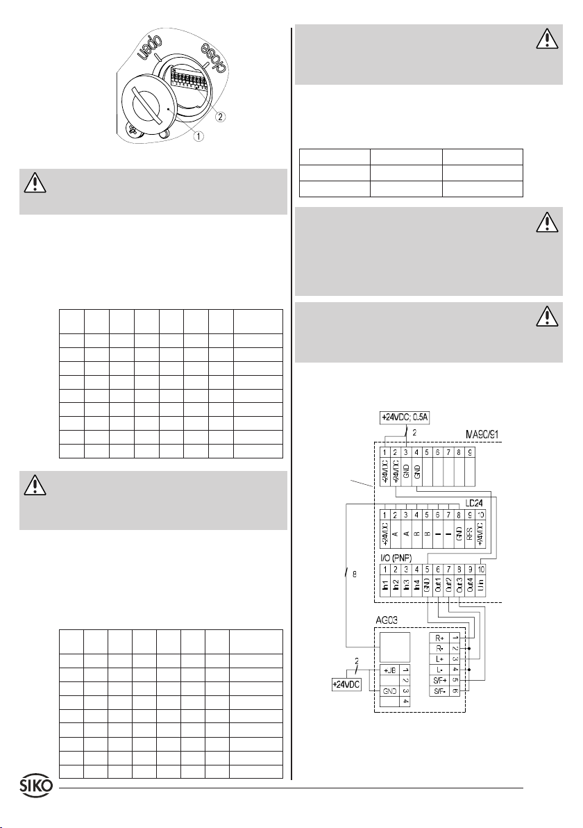
Fig. 8: Address setting
Attention
Overwinding the cover beyond the marked range
results in the loss of the type of protection.
6.5.3 Address setting (Profibus)
The slave address is entered via switches 1 - 7 in
binary format. The setting of address 127 is internally set into address 126.
This is illustrated in the following table:
SW1
SW2
SW3
SW4
SW5
SW6
SW7
[20]
[21]
[22]
[23]
[24]
[25]
OFF OFF OFF OFF OFF OFF OFF 0
ON OFF OFF OFF OFF OFF OFF 1
OFF ON OFF OFF OFF OFF OFF 2
ON ON OFF OFF OFF OFF OFF 3
..
..
..
..
..
..
OFF OFF ON ON ON ON ON 124
ON OFF ON ON ON ON ON 125
OFF ON ON ON ON ON ON 126
ON ON ON ON ON ON ON 126!
[26]
set slave
address
..
..
Attention
The DIP switch settings are read in only during
switching on voltage supply. Changing the node
address during operation has no effect.
6.5.5 Bus terminator
The internal bus terminator can be activated via
DIP switches 9 + 10:
SW9 SW10 Bus terminator
OFF OFF deactivated
ON ON active
Attention
It should be noted that both DIP switches are
•
always required for correct funktion of bus
termination.
Interruption of AG03 supply voltage causes bus
•
termination failures!
Warning
Prior to commissioning the drive, thoroughly
read the manuals. The manuals for Profibus-DP
and CANopen can be found on the attached CD.
Application example of motor control PWM, AG03
(only Digital) -> MA90 (I/O PNP)
supply
Attention
supply
The DIP switch settings are read in only during
switching on voltage supply. Changing the slave
address during operation has no effect.
6.5.4 Address setting (CAN-open)
The node address is entered via switches 1 – 7 in
encoder
binary format. The setting of address 0 is internally set into address 1.
This is illustrated in the following table:
SW1
SW2
SW3
SW4
SW5
SW6
SW7
[20]
[21]
[22]
[23]
[24]
[25]
OFF OFF OFF OFF OFF OFF OFF 1!
ON OFF OFF OFF OFF OFF OFF 1
OFF ON OFF OFF OFF OFF OFF 2
ON ON OFF OFF OFF OFF OFF 3
..
..
..
..
..
..
OFF OFF ON ON ON ON ON 124
ON OFF ON ON ON ON ON 125
OFF ON ON ON ON ON ON 126
ON ON ON ON ON ON ON 127
18 AG03 Datum 23.08.2010 Art.Nr. 83605 Änd. Stand 283/10
[26]
set slave
address
..
..
supply
encoder
Page 19
7. Accessory connector
Straight mating connector
4-pole connector (Motor/network) available from
SIKO as accessory art. no. 83526. Wire cross section is max. 0,75mm². Cable channel: 6-8mm.
8-pole connector (Inputs PWM) available from
SIKO as accessory art. no. 83527. Wire cross section is max. 0,5mm². Cable channel: 6-8mm.
8-pole connector (Incremental encoder) available
from SIKO as accessory art. no. 83525. Wire cross
section is max. 0,5mm². Cable channel: 6-8mm.
5-pole connector (Profibus In) available from SIKO
as accessory art. no. 83991. Wire cross section is
max. 0,75mm². Cable channel: 6-8mm.
5-pole connector (Profibus Out) available from
SIKO as accessory art. no. 83992. Wire cross section is max. 0,75mm². Cable channel: 6-8mm.
5-pole connector (CAN-open In) available from
SIKO as accessory art. no. 84109. Wire cross section is max. 0,75mm². Cable channel: 6-8mm.
5-pole connector (CAN-open Out) available from
SIKO as accessory art. no. 84732. Wire cross section is max. 0,75mm². Cable channel: 6-8mm.
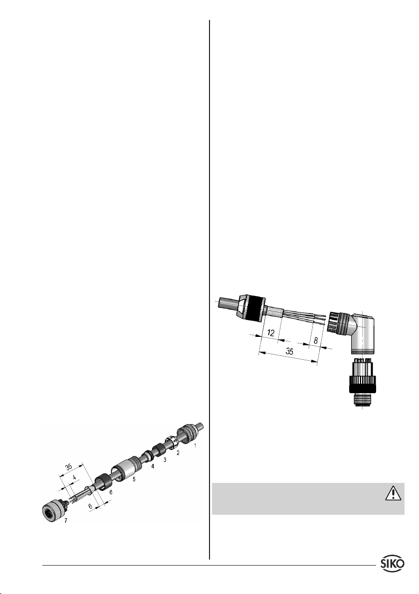
Please proceed as follows (fig. 9):
Mount seal to screen ring (4).
1.
Slip parts 1 to 6 over outer cable.
2.
Strip cable sheath, isolate conductor.
3.
Shorten and turn down screen.
4.
Clamp wires into socket (7) (follow connection
5.
diagram).
Mount parts 2 ... 6 . Place screen around screen
6.
ring (4).
Screw pressure screw (1) on coupling sleeve
7.
(5).
Right angle mating connector (5 pole)
5 pole connector (Profibus In) Available from SIKO
as accessory art. no. 82804. Wire cross section is
to be at least 0,14mm², max. 0,5mm². Cable channel: 4-8mm.
5 pole connector (Profibus Out) Available from
SIKO as accessory art. no. 82805. Wire cross section is to be at least 0,14mm², max. 0,5mm². Cable channel: 4-8mm.
5 pole connector (CAN-open In) Available from
SIKO as accessory art. no. 83006. Wire cross section is to be at least 0,14mm², max. 0,5mm². Cable channel: 4-8mm.
5 pole connector (CAN-open Out) Available from
SIKO as accessory art. no. 83007. Wire cross section is to be at least 0,14mm², max. 0,5mm². Cable channel: 4-8mm.
Please proceed as follows (fig. 10):
Thread pressure nut onto the cable.
1.
Strip the cable sheath, shorten the screen.
2.
Bare cores.
3.
Thread cores through the housing and connect.
4.
Screw housing on pin body.
5.
Tighten pressure nut.
6.
Fig. 10: Right angle mating connector
Changing the angle position (fig. 10):
Turn on female contact, slightly pull out and
1.
rotate to desired angular position (in steps
of 45°).
Screw on female contact.
2.
Attention
Multiple angle adjustments to a single direction
cause shortening of the line and break.
Fig. 9: Straight mating connector
AG03 Datum 23.08.2010 Art.Nr. 83605 Änd. Stand 283/10 19
Page 20
SIKO GmbH
Werk / Factory:
Weihermattenweg 2
79256 Buchenbach-Unteribental
Postanschrift / Postal address:
Postfach 1106
79195 Kirchzarten
Telefon/Phone +49 7661 394-0
Telefax/Fax +49 7661 394-388
E-Mail [email protected]
Internet www.siko.de
Service [email protected]
20 AG03 Datum 23.08.2010 Art.Nr. 83605 Änd. Stand 283/10
 Loading...