

Page 1
Benutzerinformation
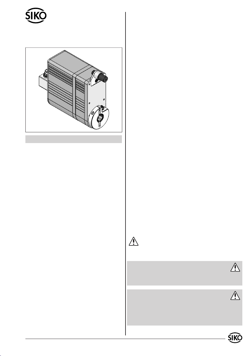
AG02
Getriebe
DEUTSCH
1. Gewährleistungshinweise
Ihr Produkt hat unser Werk in geprüftem und be-
•
triebsbereitem Zustand verlassen. Für den Betrieb
gelten die angegeben Spezifikationen und die
Angaben auf dem Typenschild als Bedingung.
Garantieansprüche gelten nur für Produkte der
•
Firma SIKO GmbH. Bei dem Einsatz in Verbindung
mit Fremdprodukten besteht für das Gesamtsystem
kein Garantieanspruch.
Reparaturen dürfen nur im Werk vorgenommen
•
werden. Für weitere Fragen steht Ihnen die Firma
SIKO GmbH gerne zur Verfügung.
Zur Wahrung Ihrer Gewährleistungsansprüche
•
müssen Sie, vor Montage und Inbetriebnahme,
dieses Dokument sorgfältig durchlesen und alle
Warnungen und Hinweise beachten.
Es ist jede Arbeitsweise zu unterlassen, welche die
•
Sicherheit mit dem Gerät beeinträchtigt.
Die vorgeschriebenen Sicherheitshinweise in
•
dieser Benutzerinformation beachten.
2.2 Montage-, Inbetriebnahme- und Bedien-
personal
Montage, Inbetriebnahme, Bedienung und Wartung darf nur durch qualifiziertes und vom Anlagenbetreiber autorisiertes Personal erfolgen.
2.3 Kennzeichnung von Gefahren und Hinwei-
sen
Sicherheitshinweise bestehen aus dem Signalzeichen und einem Signalwort.
2.3.1 Signalwörter
"Gefahr"
Hinweis auf Gefährdungen die zu schweren Körperverletzungen mit Todesfolge, Sachschäden oder
ungeplanten Gerätereaktionen führen können.
"Warnung"
Hinweis auf Gefährdungen die zu Körperverletzungen, Sachschäden oder ungeplanten Gerätereaktionen führen können.
"Vorsicht"
Hinweis auf Gefährdungen die zu Sachschäden oder
ungeplanten Gerätereaktionen führen können.
"Achtung"
Wichtige Betriebshinweise die die Bedienung erleichtern oder die bei Nichtbeachtung zu ungeplanten Gerätereaktionen führen können.
2.3.2 Signalzeichen
2. Sicherheitshinweise
2.1 Bestimmungsgemäße Verwendung
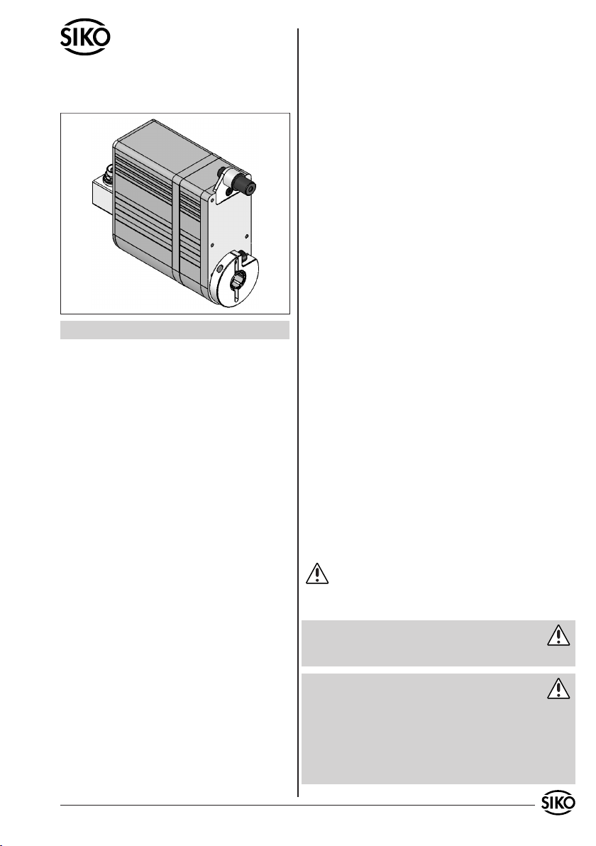
Der Stellantrieb AG02 dient Verstellaufgaben an
Anlagen und Maschinen im Industriebereich. Der
Stellantrieb darf ausschließlich zu diesen Zwecken
verwendet werden.
Eigenmächtige Umbauten und Veränderungen
•
an dem Gerät sind aus Sicherheitsgründen
verboten.
Die in dieser Benutzerinformation vorgeschrie-
•
benen Betriebs- und Installationsbedingungen
müssen eingehalten werden.
AG02 Datum 08.07.2010 Art.Nr. 82270 Änd. Stand 137/10 1
2.4 Allgemeine Sicherheitshinweise
Gefahr: Verletzungsgefahr durch Verwendung in
explosionsgefährdeten Zonen
Setzen Sie den Antrieb nicht in explosionsgefähr-
•
deten Zonen ein.
Gefahr: Verletzungsgefahr durch ungebremsten
Antrieb
Bei Spannungsausfall, Störungen und Aktionen,
•
die das Freischalten der Endstufe zur Folge
haben, kommt es zum sofortigen Verlust des
Drehmoments.
Page 2
N
S
Stellen Sie sicher, dass diese Gefährdung im
•
Bedarfsfall durch eine externe Haltevorrichtung
(z.B. Haltebremse) verhindert wird.
Warnung: Verletzungsgefahr durch rotierende
Teile
Klemmring und Hohlwelle sind rotierende Teile,
•
von denen Gefährdungen wie Quetschen, Erfassen
und Reibung ausgehen können.
Verhindern Sie die Zugriffsmöglichkeit auf diese
•
Teile durch geeignete Schutzmaßnahmen.
Warnung: Verbrennungsgefahr
Im Betrieb können an der Gehäuseoberfläche
•
Temperaturen >60°C auftreten.
Verhindern Sie die Zugriffsmöglichkeit auf das
•
Gehäuse und schützen Sie temperaturempfindliche Anlagenteile durch geeignete Schutzmaßnahmen.
Vorsicht: Generatorischer Betrieb
Bei hoher Schwungmasse am Abtrieb kann der
•
Antrieb beim Abbremsen in den generatorischen
Betrieb übergehen. Dabei wird mechanische
Energie in elektrische Energie umgewandelt.
Dies führt zu einem unmittelbaren Anstieg der
Zwischenkreisspannung, da der Antrieb nicht
rückspeisefähig ist.
Reduzieren Sie die Verfahrgeschwindigkeit bzw.
•
die Beschleunigung umgehend nach dem erstmaligen Auftreten des Fehlers "Überspannung
Zwischenkreis".
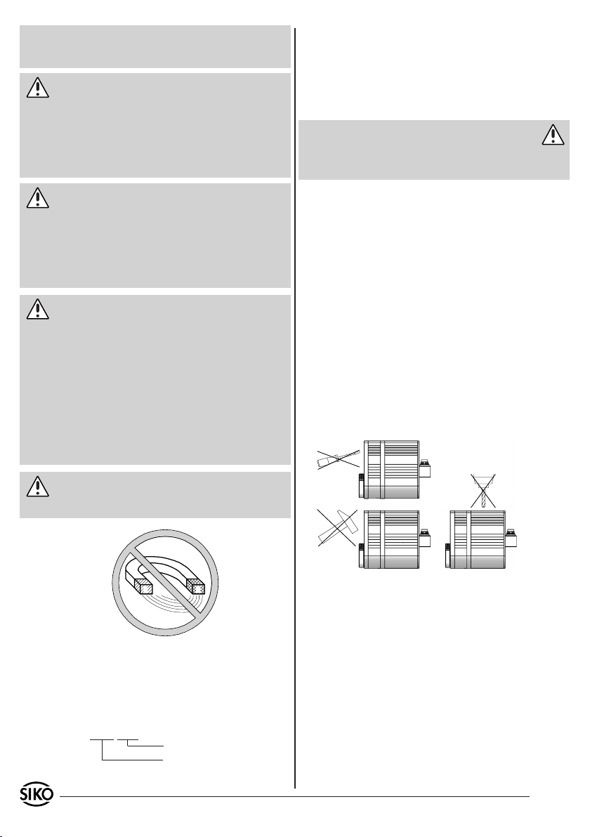
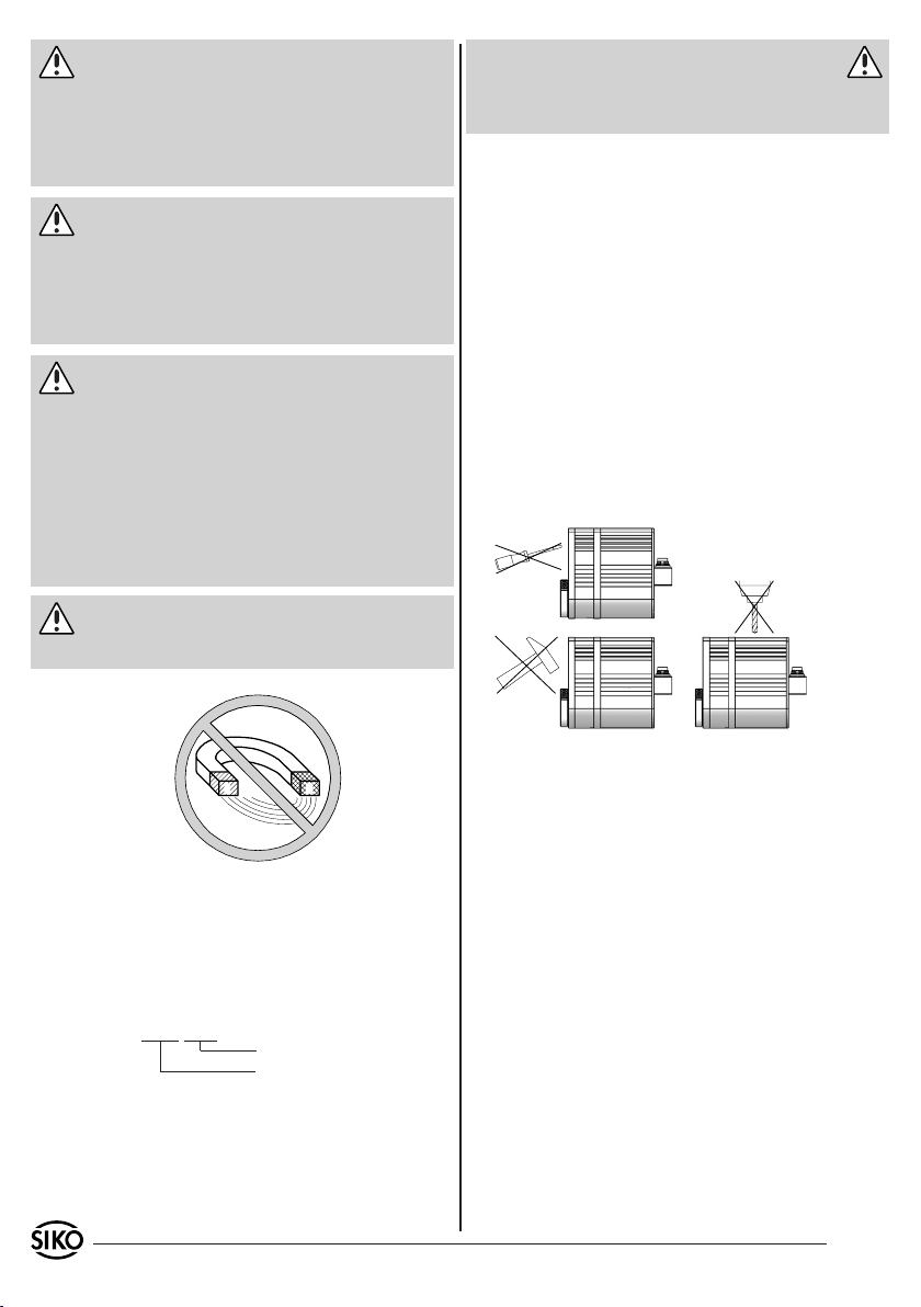
Vorsicht: Störung durch Fremdmagnete
Schützen Sie den Antrieb vor Einflüssen von
•
Fremdmagneten.
4. Mechanische Montage
Die Montage darf nur gemäß der angegebenen IPSchutzart vorgenommen werden. Das Gerät muss
ggfs. zusätzlich gegen schädliche Umwelteinflüsse, wie z.B. Spritzwasser, Staub, Schläge, Temperatur geschützt werden.
Warnung: Verlust der Schutzart
Radialdichtringe sind Verschleißteile! Die Schutzart ist deshalb abhängig von Lebensdauer und Zustand der Dichtringe.
Montagehinweise
Gehen Sie sorgfältig mit dem Getriebe um. Folgende Punkte führen unverzüglich zum Verfall der
Garantie:
Zerlegen oder Öffnen des Getriebes (soweit dies
•
nicht in dieser Benutzerinformation beschrieben
wird).
Schläge auf das Getriebe oder die Welle, da
•
dadurch interne Elemente wie z.B. die optische
Kodescheibe beschädigt werden können.
Mechanische Bearbeitung am Getriebe (Bohren,
•
Fräsen, usw.). Hierdurch kann es zu schweren
Beschädigungen kommen.
Unzulässige axiale oder radiale Belastung der
•
Welle oder Überbelastung des Getriebes.
Unsachgemäße Befestigung des Getriebes.
•
Abb. 1: Montagehinweise
Anbau des Getriebes
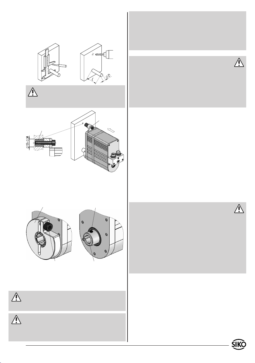
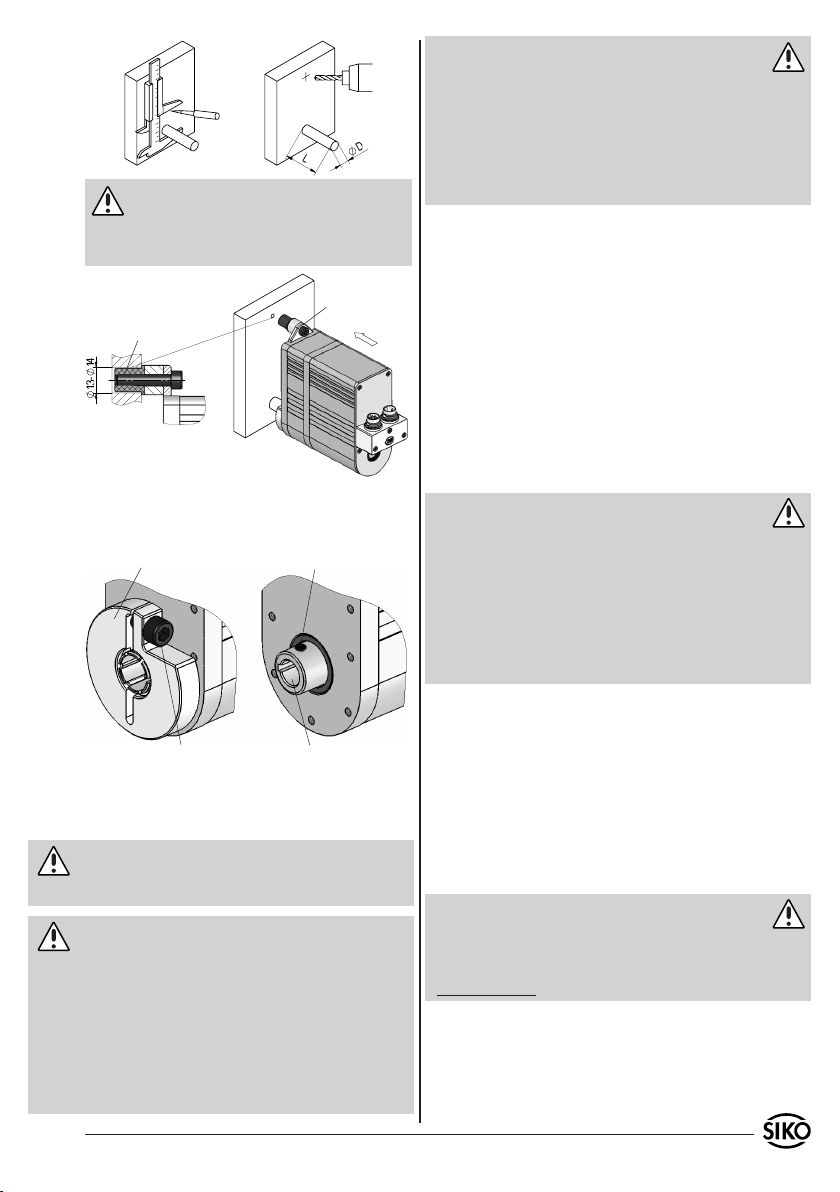
Die Befestigung erfolgt mittels Drehmomentab-
•
stützung (Lasche siehe Abb. 2) und Klemmung
der Welle. Montieren Sie das Getriebe möglichst
3. Identifikation
Das Typenschild zeigt den Gerätetyp mit Variantennummer. Die Lieferpapiere ordnen jeder Variantennummer eine detaillierte Bestellbezeichnung zu.
z.B. AG02-0023
Varianten-Nr.
Geräte-Typ
2 AG02 Datum 08.07.2010 Art.Nr. 82270 Änd. Stand 137/10
verspannungsfrei. Für die radiale spielfreie Montage eignet sich die an der Lasche befindliche
Elastomere-Spannbuchse.
Die Spannbuchse bis zum Anschlag in die
•
Montagebohrung (siehe Abb. 2) schieben und
festziehen.
Kräfte dürfen nicht durch das Gehäuse übertragen
•
werden. Sie dürfen ausschließlich an der Welle
des Geräts wirken.
Page 3
0
10
20
30 40
50
60 70 80
0
Achten Sie auf geringen Winkel und parallelen
•
Versatz zwischen Welle und Anflanschfläche.
Bei nicht korrekter Lage entstehen Spannungen
im Lager, die über erhöhte Erwärmung bis zur
Zerstörung der Lager führen können.
Vorsicht: Wellenlänge
Länge "L" des kundenseitigen Wellenstumpfes darf bei
Übersetzung 55 max. 40mm, bei Übersetzung 62 max.
50mm betragen (gilt nur bei Ausf. mit Sackloch).
Empfehlung: Kundenseitiger Wellendurchmesser ø14f8
versehen.
Vor dem Einschalten sind alle Leitungsanschlüsse
•
und Steckverbindungen zu überprüfen.
Die Betriebsspannung des Gebers muss gemein-
•
sam mit der der Folgeelektronik (z.B. Steuerung)
eingeschaltet werden.
Achtung: Störsicherheit
Alle Anschlüsse sind gegen äußere Störeinflüsse
•
geschützt. Der Einsatzort ist aber so zu wählen,
dass induktive oder kapazitive Störungen nicht
auf den Antrieb oder dessen Anschlussleitungen einwirken können!
Durch geeignete Kabelführung und Verdrahtung
•
können Störeinflüsse vermindert werden.
Erforderliche Maßnahmen:
Nur geschirmtes Kabel verwenden. Den Kabel-
•
schirm beidseitig auflegen.
Die Verdrahtung von Abschirmung und Masse (0V)
•
Elastomere
Spannbuchse
Lasche
muss sternförmig und großflächig erfolgen.
Das System muss in möglichst großem Abstand von
•
Leitungen eingebaut werden, die mit Störungen
belastet sind; ggfs. sind zusätzliche Maßnahmen
wie Schirmbleche oder metallisierte Gehäuse
Abb. 2: Anbaumöglichkeiten
Das Antriebsmoment wird über den Klemmring oder
•
die Passfeder (siehe Abb. 3) auf die anzutreibende
Welle übertragen.
Klemmring
Gewindestift
vorzusehen. Leitungsführungen parallel zu Energieleitungen vermeiden.
Schützspulen müssen mit Funkenlöschgliedern
•
beschaltet sein.
Vorsicht: EMV
Um die elektromagnetische Verträglichkeit
•
des Antriebes zu gewährleisten, sind folgende
Maßnahmen erforderlich (nur bei Geber: Absolut
magnetisch ABM):
Klappferrit (im Lieferumfang) an der Versor-
•
gungsleitung dicht am 3-pol. Steckverbinder
anbringen.
Erdung des Antriebes über den vorgesehenen
Montage nur mit montierter Welle zulässig
Hohlwelle mit Passfedernut nach DIN 6885/1
•
Flachsteckeranschluss mit einem Litzenquerschnitt von min. 4mm².
Abb. 3: Montage Antriebswelle
5. Elektrischer Anschluss
Warnung
Steckverbindungen dürfen nie unter Spannung
•
gesteckt oder abgezogen werden!
Achtung
Alle Verdrahtungsarbeiten dürfen nur spannungs-
•
los erfolgen.
Litzen sind mit geeigneten Aderendhülsen zu
•
AG02 Datum 08.07.2010 Art.Nr. 82270 Änd. Stand 137/10 3
Spannungsversorgung
Die Versorgung des Antriebes ist ausreichend zu
dimensionieren, da die Stromaufnahme kurzzeitig
bis zu 6A (150W-Motor), bzw. 3A (70W-Motor)
betragen kann. Der Litzenquerschnitt für die Versorgung des Antriebes muss deshalb min. 0,5mm²
betragen. Die Spannungswerte sind abhängig von
der Geräteausführung und sind den Lieferpapieren
oder dem Typenschild zu entnehmen.
Page 4
Gefahr: Überlastung
Zur Absicherung des Antriebes ist zusätzlich zur
internen Strombegrenzung eine kundenseitige Sicherung vorzusehen. Max. Strombelastung siehe
"Leistungsaufnahme".
Motor : 0...24VDC
Inkrementalgeber OP/LD24 : 24 VDC ±20%
Inkrementalgeber LD5 : 5 VDC ±5%
Auflösung Inkr. Geber : 1000 Imp./Umdr.
Auflösung Abs. Geber : 1600 Imp./Umdr.
Potentiometer mit : 12...28 VDC
R/I Wandler (MWI) oder R/U Wandler (MWU)
Zulässige Leistungsaufnahme
Inkrementalgeber OP/LD24 : < 25mA
Inkrementalgeber LD5 : < 50mA
Steuerelektronik : < 150mA (Inkr.)
Steuerelektronik : < 170mA (Absolut
magnetisch)
Motor Max. Strombelastung
Kurzzeitbetrieb S2; 25%ED
Motor (150W) 5,8A
Motor (70W) 3A bei i = 55,3 / 62,2
2,1A bei i = 135,8
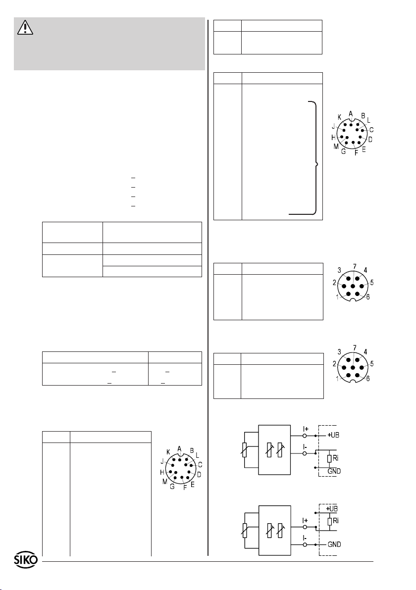
PIN Belegung
L N.C.
M +UB (verpolgeschützt)
Inkrementalgeber (LD5) 12-pol. Stiftkontakt:
PIN Belegung
A Signal /B
B +SUB (Sensor)
C Signal /I
D Signal I
E Signal A
F Signal /A
G N.C.
H Signal B
*
Ansichtsseite =
Steckseite
J N.C.
K GND
L SGND (Sensor)
}*
M +UB
* intern verbunden
Potentiometer ohne Messwandler (P10) 7-pol.
Stiftkontakt:
PIN Belegung
1 Pe Endstellung
Kurzzeitbetrieb S2 (Auszug aus den Bestimmungen
DIN 57530, VDE 0530, Teil 1)
Betrieb mit konstantem Belastungszustand für be-
2 Po Anfangsstellung
3 S Schleiferkontakt
4-7 N.C.
Ansichtsseite =
Steckseite
grenzte, festgelegte Zeit (t on) mit anschließender
Pause (t off), bis der Motor die Umgebungstemperatur wieder erreicht hat!
Beispiel: t on off
< 2,5s > 7,5s
< 2,5min > 7,5min
5.1 Anschlussbelegung
Inkrementalgeber (OP/LD24) 12-pol. Stiftkon-
takt:
Potentiometer mit R/I Wandler (MWI) 7-pol.
Stiftkontakt:
PIN Belegung
1 I2 I+
3-7 N.C.
Ansichtsseite =
Steckseite
Anschluss Messwandler (MWI) Bürde gegen Masse:
Folgeelektronik
PIN Belegung
A Signal /B
B N.C.
C Signal /I
D Signal I
E Signal A
F Signal /A
Ansichtsseite =
Steckseite
Anschluss Messwandler (MWI) Bürde gegen +UB:
Folgeelektronik
G N.C.
H Signal B
J N.C.
K GND
4 AG02 Datum 08.07.2010 Art.Nr. 82270 Änd. Stand 137/10
Page 5
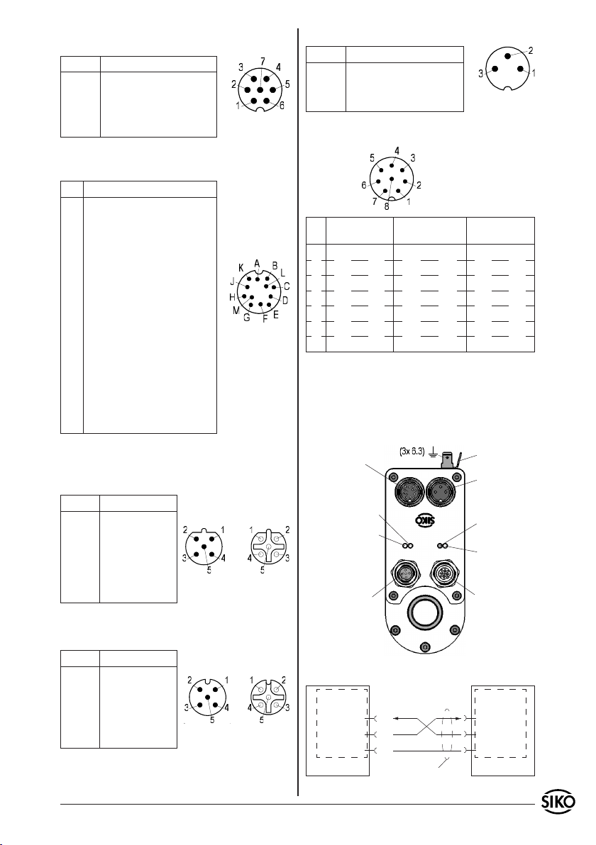
Potentiometer mit R/U Wandler (MWU) 7-pol.
Stiftkontakt:
PIN Belegung
1 GND
2 +24VDC
3 Uout
4-7 N.C.
Ansichtsseite =
Steckseite
Steuersignale/Schnittstelle (absolut magnetisch) 12-pol. Stiftkontakt:
PIN Belegung
A ES1
B ES2
Endschalter 1;
24VDC±20%
Endschalter 2;
24VDC±20%
C Freigabe 24VDC±20%
D N.C.
E +24VDC
Ausgang
max. 200mA
F N.C.
G RXD/DÜA RS232/RS485
H TXD/DÜB RS232/RS485
Ansichtsseite =
Steckseite
J GND Schnittstelle
K GND
L CAL
Endschalter 1+2;
Freigabe; CAL
Kalibrierschalter;
24VDC±20%
M GND siehe Kap. 4.6
Profibus-DP (PB) Bus-Ein 5-pol. Stiftkontakt,
Bus-Aus 5-pol. Buchsenkontakt (absolut magnetisch):
PIN Belegung
1 +5VDC für Ab-
schlusswiderstände
Bus-Ein Bus-Aus
2 BUS A
3 GND
4 BUS B
Ansichtseite = Steckseite
5 N.C.
Motor / Netz 3-pol. Stiftkontakt:
PIN Belegung
1 +M / +UB
2 N.C.
3 -M / GND
Ansichtsseite =
Steckseite
Eingänge Motorsteuerung PWM 8-pol. Stiftkontakt:
Ansichtsseite =
Steckseite
PIN Ausf. Digital Ausf.Analog uni-
polar
1 Rechtslauf Plus Enable Plus Enable Plus
2 Rechtslauf Masse Enable Masse Enable Masse
3 Linkslauf Plus Rechts/Links Plus N.C.
4 Linkslauf Masse Rechts/Links Masse N.C.
5 Eil/Schleich Plus Analog 0...+10V Analog -10...+10V
6 Eil/Schleich Masse Analog Masse Analog Masse
7+8 N.C. N.C. N.C.
Ausf.Analog bipolar
5.2 Anschluss Schnittstelle (RS232/RS485) (nur
absolut magnetisch)
Der Anschluss der seriellen Schnittstelle RS232
bzw. RS485 erfolgt über den 12-pol. Steckverbinder (Abb. 4).
Endschalter,
Schnittstelle,
Kalibrierschalter,
Freigabe
grün: Endschalter 1
grün: Endschalter 2
Bus IN
PE
Netz
rot: Störung
bzw. Freigabe
nicht aktiv
gelb: Profibus
(optional)
Bus OUT
CANopen (CAN) Bus-Ein 5-pol. Stiftkontakt, BusAus 5-pol. Buchsenkontakt (absolut magnetisch):
PIN Belegung
1 N.C.
2 N.C.
3 GND
4 CAN_H
5 CAN_L
Bus-Ein Bus-Aus
Ansichtseite = Steckseite
Abb. 4: Anschlüsse AG02
Schnittstelle
RS232
RXD
(G)
TXD
(H)
GND
(J)
AG02
Schirm auf PE legen
Schnittstelle
RS232
RXD
TXD
GND
PC
Abb. 5: Anschlussschema Schnittstelle RS232
AG02 Datum 08.07.2010 Art.Nr. 82270 Änd. Stand 137/10 5
Page 6
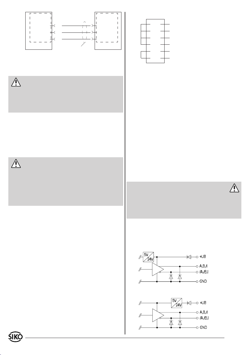
Schnittstelle
RS485
DÜA
DÜB
GND
AG02
(G)
(H)
(J)
Schirm auf PE legen
Schnittstelle
RS485
DÜA
DÜB
GND
PC
Abb. 6: Anschlussschema Schnittstelle RS485
5.3 Anschluss Kalibrierschalter (nur absolut
magnetisch)
Achtung
Der Anschluss des Kalibrierschalters erfolgt über
den 12-pol. Steckverbinder. Der Eingang arbeitet
High–Aktiv. Das bedeutet, dass bei Anlegen von
24VDC an den + Eingang eine Kalibrierung des Antriebes durchgeführt wird.
Der Eingang des Kalibrierschalters ist optoentkoppelt.
5.4 Anschluss Endschalter/Freigabe (nur bei
Geber: Absolut magnetisch)
Fall 1: Mit Endschalter-/Freigabe Verdrahtung
Achtung
Der Anschluss der beiden Endschalter sowie der
Freigabe erfolgt über den 12-pol. Steckerverbinder. Bei nicht aktivem Endschalter muss am + Eingang des Endschalters eine Spannung von 24VDC
anliegen. Damit der Antrieb verfahren werden
kann, muss am Freigabeeingang ebenfalls eine
Spannung von 24VDC anliegen.
Diese 24VDC können nach Bedarf aus den Klemmen
Pin "E" und "M" bezogen werden. Dies ermöglicht
eine wirtschaftliche Verdrahtung.
Jedoch ist dann zu beachten, dass durch diese
Verdrahtung die galvanische Trennung zwischen
der Geräteversorgung und den Steuereingängen
aufgehoben ist.
Die Eingänge der Endschalter bzw. der Freigabe
sind optoentkoppelt.
Vorschlag für PIN-Überbrückung:
E
A
B
C
K
M
24V Ausgang
Endschalter 1 ES1 (24V)
Endschalter 2 ES2 (24V)
Freigabe (24V)
GND ES
GND
Ist Endschalter 1 oder Endschalter 2 nicht aktiv,
so wird dies durch eine grüne LED signalisiert (siehe Abb. 4). Ist die Freigabe nicht aktiv, wird dies
durch eine rote LED signalisiert (siehe Abb. 4).
6. Inbetriebnahme
Bitte beachten Sie die Hinweise auf ordnungsgemäßen mechanischen und elektrischen Anschluss.
Nur dann sind die Voraussetzungen für eine problemlose Inbetriebnahme und einwandfreien Betrieb gegeben.
Prüfen Sie vor der Inbetriebnahme insbesondere
nochmals auf:
korrekte Polung der Betriebsspannung.
•
korrekten Anschluss des Kabels und der Signale.
•
festen Sitz des Getriebes und der Hohlwelle.
•
korrekte Montage und Funktion der Endschalter
•
Warnung: Latchup-Effekte
Die Betriebsspannung des Gerätes muss gemeinsam mit der der Folgeelektronik (z.B. Steuerung)
eingeschaltet werden, um Latchup-Effekte an den
Ausgängen des Gerätes zu vermeiden (nur bei Inkrementalgeber).
6.1 Geber Inkremental
Ausgangsschaltung
OP Gegentakt (Push-Pull), differentiell
Fall 2: Ohne Endschalter/Freigabe Vedrahtung
Werden keine Endschalter bzw. Freigabe benötigt,
sind die Eingänge der Endschalter bzw. Freigabe
permanent auf 24VDC zu legen!
6 AG02 Datum 08.07.2010 Art.Nr. 82270 Änd. Stand 137/10
LD24 Leitungstreiber, differentiell
Page 7
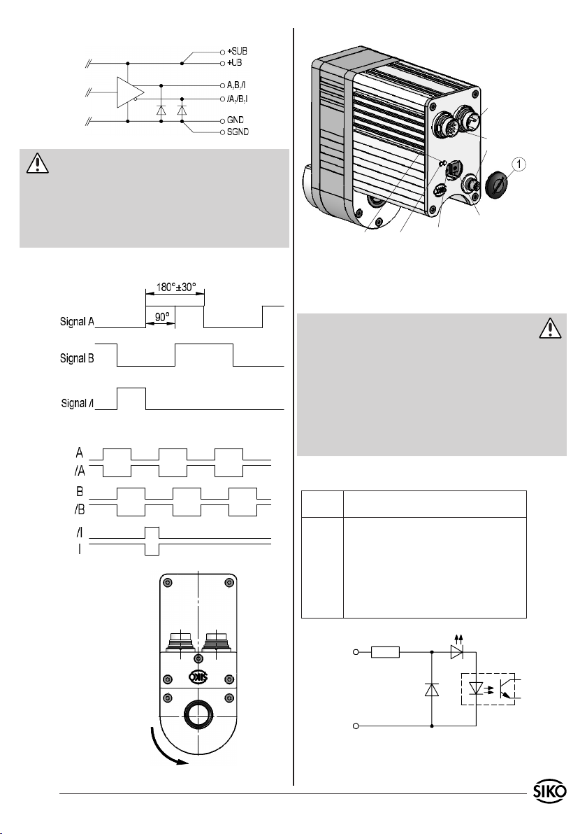
Vorsicht: LD24, LD5
Die Geberausgänge entsprechen der Spezifikation
RS422A. Deren Ausgänge können eine Last bis zu
70mA treiben, sind kurzschlussfest und besitzen
eine thermische Abschaltung. Bei Verwendung
sämtlicher Ausgangskanäle darf die Last/Kanal
35mA nicht überschreiten.
6.2 Motorsteuerung PWMLD5 Leitungstreiber, differentiell
Netz
Geber
Eingänge
P2 (nur bei Digital)
LED 1+2LED 3+4
P1 (nur bei Digital)
Ausgangssignale / Impulsbild
Abb. 7: Toleranzbereich der Ausgangssignale
Einstellen der Potentiometer
Nach Lösen des Verschlussdeckels (1) sind die Potentiometer P1 und P2 zugänglich.
Warnung
Schutzartbedingt darf lediglich der Verschlussde-
•
ckel (1) gelöst werden.
Bei gelöstem Verschlussdeckel (1) ist die Schutzart
•
des Antriebes nicht mehr gewährleistet.
Parameter an den Trimmpotentiometern, mittels
•
2mm Schlitzschraubendreher einstellen.
Bei Wiedermontage des Verschlussdeckel (1) auf
•
korrekten Sitz der Dichtung achten!
Nur bei Ausf. Digital:
Potenti-
Beschreibung
ometer
P1 Einstellung der Geschwindigkeit im Schnell-
gang; PWM stufenlos 0...100% (linker
Anschlag 0%; rechter Anschlag 100%).
Eingang schnell/langsam aktiv.
P2 Einstellung der Geschwindigkeit im
Schleichgang; PWM stufenlos 0...100% (linker Anschlag 0%; rechter Anschlag 100%).
Eingang schnell/langsam inaktiv.
Rechtslauf+
Linkslauf+
Eil/Schleich+
RechtslaufLinkslauf-
Drehrichtung e; im
montiertem Zustand
A vor B
Eil/Schleich-
Abb. 9: Eingangsschaltung Digitaleingänge
Abb. 8: Impulsbild
AG02 Datum 08.07.2010 Art.Nr. 82270 Änd. Stand 137/10 7
Page 8
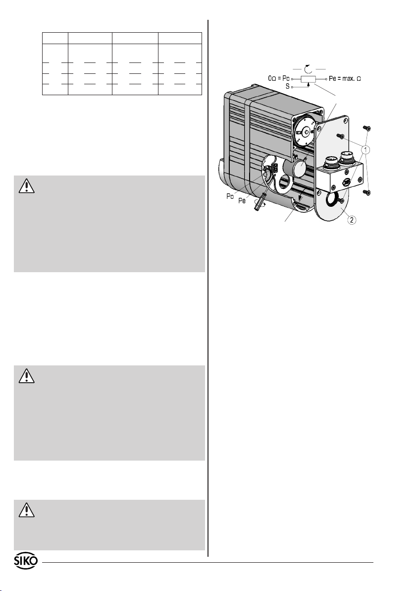
Anzeigen:
LED Digital Analog unipolar Analog bipolar
1, gelb blinkt 600ms=
Start Up
2, blau Rechts Enable Enable
3, blau Links Rechts/Links N.C.
4, gelb Eil/Schleich N.C. N.C.
blinkt 300ms=
Current
Error,
On = Betrieb
6.3.2.1 Einstellen des Messwandlers (MWI)
Nach Lösen der Befestigungsschrauben (1) und
Öffnen des Gehäusedeckels (2), sind die Trimmpotentiometer zugänglich.
Potentiometer
6.3 Geber potentiometrisch mit/ohne Messwandler
6.3.1 Einrichtung Potentiometer (P10)
Nach ordnungsgemäßem Anschluss zeigt das Gerät
bei Einschalten der Betriebsspannung den aktuellen Istwert.
Achtung: Drehrichtung
Der Messbereich des Potentiometers resultiert aus
der Übersetzung des Potentiometergetriebes. Ab
Werk wird das Potentiometer im Linksanschlag
voreingestellt (siehe Abb. 10). Durch eine Messung des Widerstandswertes zwischen 'Po' und 'S'
kann die Drehrichtung überprüft werden:
R = 0 Ohm: Drehrichtung i
R = max. Wert: Drehrichtung e
6.3.2 Einstellen und Abgleich des R/I-Wandlers
(MWI)
Ist das Gerät mit einem Widerstands-Stromwandler ausgestattet, wird der Potentiometer-Widerstand in einen Strom von 4...20mA umgewandelt.
Es handelt sich um eine Zweileitertechnik. Der
Messstrom dient gleichzeitig zur Versorgung des
Drehrichtung Antriebswelle nach dem Einschalten
Abb. 10: Einstellen Trimmpotentiometer MWI
Mit Trimmpotentiometer Po kann ein Strom von
•
4mA bei Potentiometerwerten von 0 bis 15% des
Gesamtwertes eingestellt werden.
Mit Trimmpotentiometer Pe kann ein Strom von
•
20mA bei Potentiometerwerten von 90 bis 100%
des Gesamtwertes eingestellt werden.
Der kleinste nutzbare Bereich des Potentiometers, in dem 4...20mA abgegeben werden, beträgt
demnach 15% bis 90% des Potentiometer-Widerstandsbereichs.
Wandlers.
Achtung: Drehrichtung
Der Messwandler ist bei Auslieferung auf Standardwerte, 4mA für die Anfangsstellung (Po) und 20mA
für die Endstellung (Pe) des Potentiometers abgeglichen. Durch eine Messung des Stroms zwischen
den Anschlüssen 'I+' und 'I-' kann die Drehrichtung
überprüft werden:
Strom I = 4mA: Drehrichtung e
Strom I = 20mA: Drehrichtung i
Dieser Messbereich entspricht dem vom Kunden
ausgewählten Übersetzungsbereich des Potentiometergetriebes.
Achtung: Trimmpotentiometer
Durch zwei Trimmpotentiometer Po und Pe (siehe
Abb. 10) können diese Werte an die tatsächlichen
Anfangs- und Endstellungen der Anwendung angepasst werden.
8 AG02 Datum 08.07.2010 Art.Nr. 82270 Änd. Stand 137/10
6.3.2.2 Abgleich des Messwandlers (MWI)
Maschine vor der Montage des Antriebes auf
1.
Anfangsstellung fahren.
- Bei Ausf. mit Klemmring: Antrieb montieren
2.
und fixieren (siehe Abb. 3).
- Bei Ausf. mit Passfedernut: Antrieb bis Anschlag
auf Welle schieben und drehen, bis Drehmomentabstützung in gewünschter Lage fixiert werden
kann (siehe Abb. 2). Getriebe mit Gewindestift
axial sichern.
Trimmpotentiometer Po drehen, bis Anfangswert
3.
(4mA) gemessen wird.
Maschine auf Endstellung fahren.
4.
Trimmpotentiometer Pe drehen, bis Endwert
5.
(20mA) gemessen wird.
Gehäusedeckel wieder montieren.
6.
Die Schritte 3 bis 5 sind solange zu wiederholen,
bis die Werte austariert sind (iterativer Abgleich).
Page 9
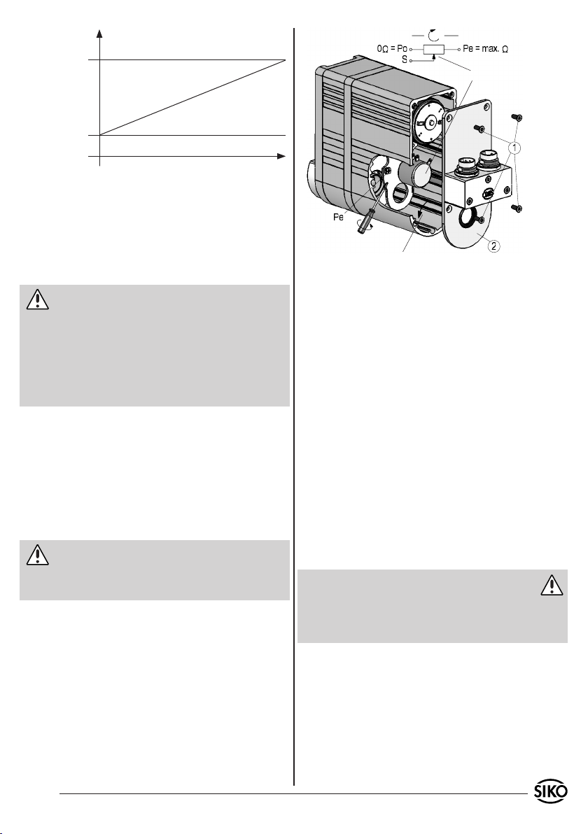
Ausgangsstrom
20mA
4mA (Po)
(Pe)
Potentiometer
0
Messweg
Abb. 11: Abgleich
6.3.3 Abgleich des R/U-Wandlers (MWU)
Ist das Gerät mit einem Widerstands-Spannungswandler ausgestattet, wird der PotentiometerWiderstand in eine Spannung von 0...10VDC
umgewandelt. Der Anschluss erfolgt über eine
Dreileitertechnik.
Achtung: Drehrichtung
Der Messwandler ist bei Auslieferung auf den Anfangswert von 0V und den Endwert 10V Ausgangsspannung (Pe) abgeglichen. Durch eine Messung
der Spannung zwischen den Anschlüssen 'GND' und
'Uout' kann die Drehrichtung überprüft werden:
Spannung U = 0V: Drehrichtung e
Spannung U = 10V: Drehrichtung i
Dieser Messbereich entspricht dem vom Kunden
ausgewählten Übersetzungsbereich des Potentiometergetriebes. Der Ausgang des Messwandlers
sollte mit einem Widerstand 2...10KΩ gegen GND
beschaltet werden, damit sich der Anfangswert
0V einstellt. Die Ausgangslast sollte jedoch so dimensioniert sein, dass in der Endstellung (10V)
ein Ausgangsstrom von 15mA nicht überschritten
wird.
Achtung: Trimmpotentiometer
Mit dem Trimmpotentiometer (siehe Abb. 12) kann
der Endwert an die tatsächliche Endstellung der
Anwendung angepasst werden.
6.3.3.1 Einstellen des Messwandlers (MWU)
Nach Lösen der Befestigungsschrauben (1) und
Öffnen des Gehäusedeckels (2), sind die Trimmpotis zugänglich.
Drehrichtung Antriebswelle nach dem Einschalten
Abb. 12: Einstellen Trimmpotentiometer MWU
Mit Trimmpotentiometer Pe kann die Spannung
•
von 10V bei Potentiometerwerten von 60 bis 100%
des Gesamtwertes eingestellt werden.
6.3.3.2 Abgleich des Messwandlers (MWU)
Maschine auf Endstellung fahren
1.
Potentiometer (Pe) drehen, bis eine Ausgangs-
2.
spannung (10V) gemessen wird.
6.4 Geber absolut magnetisch (Profibus-DP;
CANopen; serielle Schnittstellen)
Nach ordnungsgemäßer Montage und Verdrahtung kann der Antrieb durch Einschalten der 24V
Versorgung in Betrieb genommen werden. Grünes Leuchten der beiden LED's signalisiert, dass
keine Endschalter aktiv sind (siehe Abb. 4). Das
Standardprotokoll ermöglicht nun eine individuelle Parametrierung des Antriebes über die serielle
Schnittstelle RS232 bzw. RS485.
Warnung
Vor Inbetriebnahme des Antriebes die Handbü-
cher sorgfälltig durchlesen. Die Handbücher für
Profibus-DP, CANopen und serielle Schnittstellen sind der beigefügten CD zu entnehmen.
AG02 Datum 08.07.2010 Art.Nr. 82270 Änd. Stand 137/10 9
Page 10
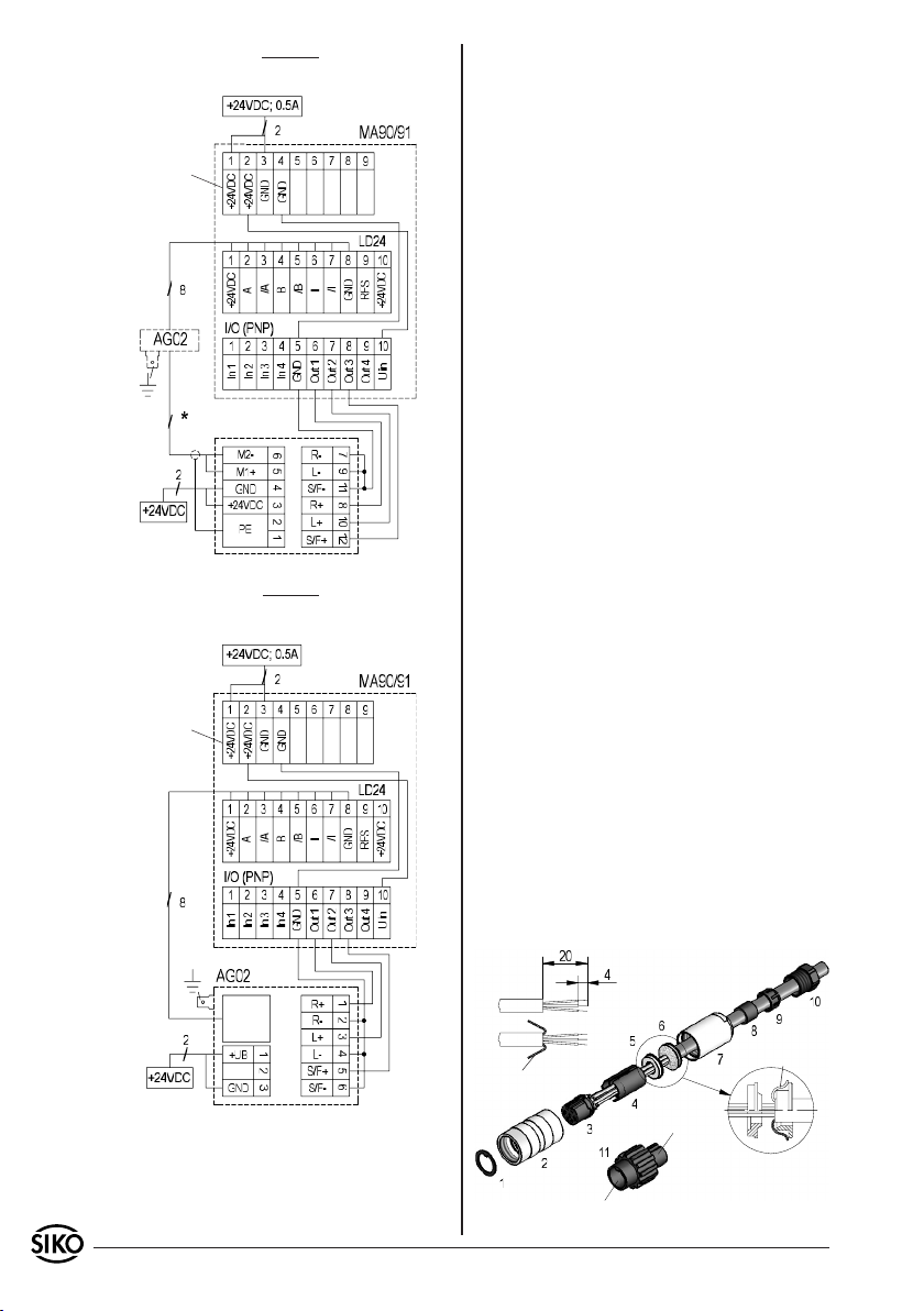
Applikationsbeispiel externe Motorsteuerung
MS02 -> AG02 -> MA90 (I/O PNP)
Versorgung
Versorgung
Geber
Motor
MS02
(digitaler Eingang)
Versorgung
Applikationsbeispiel interne Motorsteuerung
PWM, AG02 (nur Digital) -> MA90 (I/O PNP)
Versorgung
Versorgung
Geber
7. Zubehör Anschluss-Stecker
Gegenstecker gerade (Inkremental, Potentiometer,
Motor/Netz)
Bei SIKO als Zubehör unter Art.Nr. 76572 (Inkre-
mentalgeber 12-pol.) erhältlich. Litzenquerschnitt
der Leitungen min. 0,14mm², max. 0,25mm². Kabeldurchlass: 6-8mm.
Bei SIKO als Zubehör unter Art.Nr. 76141 (Poten-
tiometer 7-pol.) erhältlich. Litzenquerschnitt der
Leitungen min. 0,14mm², max. 0,5mm². Kabeldurchlass: 4-6mm.
Bei SIKO als Zubehör unter Art.Nr. 82182 (Motor/
Netz 3-pol.) erhältlich. Litzenquerschnitt der Leitungen 2x0,75mm². Kabeldurchlass: 4-6mm.
Bei der Stecker-Montage gehen Sie bitte schrittweise vor (Abb. 13):
Teile 6 ... 10 über Kabelmantel schieben.
1.
Kabel abisolieren.
2.
Schirm umlegen.
3.
Schirmring (5) auf Litzen schieben.
4.
Litzen an Einsatz (3) löten (entspr. Anschluss-
5.
plan).
Abstandhülse (4) aufweiten und über Litzen
6.
stülpen, zusammendrücken und auf Einsatz (3)
stecken. Schlitz und Nut von (3) und (4) müssen
deckungsgleich sein.
Schirmklemmring (6) an Schirmring (5) drücken,
7.
überstehenden Schirm abschneiden.
Gewindering (2) und Kupplungshülse (7) auf-
8.
schieben und mittels Montagewerkzeug (11)
verschrauben.
Dichtring (8) in Klemmkorb (9) stecken, beides
9.
in Kupplungshülse (7) schieben.
Druckschraube (10) mit Kupplungshülse (7)
10.
verschrauben.
Dichtring (1) in Gewindering (2) schieben.
11.
Geber
Versorgung
Schirm
Buchsenteil
Stiftteil
Schirm
Abb. 13: Gegenstecker gerade
10 AG02 Datum 08.07.2010 Art.Nr. 82270 Änd. Stand 137/10
Page 11
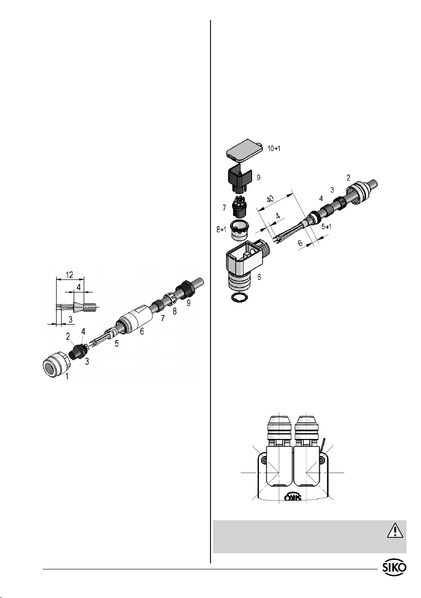
Gegenstecker gerade 8-pol. (Eingänge PWM)
Bei SIKO als Zubehör unter Art.Nr. 81351 (Eingän-
ge PWM 8-pol.) erhältlich. Litzenquerschnitt der
Leitungen max. 0,14mm². Kabeldurchlass: max.
5mm.
Bei der Stecker-Montage gehen Sie bitte schrittweise vor (Abb. 14):
Dichtungen (2 & 4) an den Buchseneinsatz (3)
1.
montieren.
Druckschraube (9), Klemmkorb (8), Dichtring
2.
(7) und Schnapphülse (6) auf das Kabel auf-
Litzen durch das Gehäuse (6) führen.
4.
Schirmring (5) und Klemmkorb (3) montieren.
5.
Druckschraube (2) leicht andrehen.
6.
Litzen nach Anschlussplan an Kontakteinsatz
7.
(7) löten.
Positionshülse (8) in Winkelstellung montieren.
8.
Kontakteinsatz (7) und Distanzhülse (9) ein-
9.
setzen.
Deckel (10) einhaken.
10.
Druckschraube (2) festziehen (ca.10-20Ncm).
11.
fädeln.
Druckschraube (9) leicht andrehen.
3.
Kabel abmanteln, Leiter abisolieren und ver-
4.
zinnen.
Schirm kürzen und umlegen.
5.
Schirmmanschette (5) an Kabeldurchmesser an-
6.
passen, aufstecken und mit Schirm verlöten.
Buchseneinsatz (3) anlöten und einschrauben,
7.
hierzu Druckschraube (9) lösen.
Gewindering (1) montieren.
8.
Druckschraube (9) festziehen.
9.
Abb. 15: Gegenstecker gewinkelt
Ändern der Winkelstellung (Abb. 15 + 16):
Druckschraube (6) leicht aufdrehen.
1.
Gewindering (8) entfernen.
2.
Kontakteinsatz (7) leicht herausziehen und
3.
in gewünschte Winkelstellung (45° Schritte)
Abb. 14: Gegenstecker gerade
Gegenstecker gewinkelt (3-pol.; 12-pol.)
verdrehen.
Kontakteinsatz montieren, Gewindering und
4.
Druckschraube aufschrauben.
Bei SIKO als Zubehör unter Art.Nr. 79666 (Inkre-
mentalgeber 12-pol.) erhältlich. Litzenquerschnitt
der Leitungen min. 0,14mm², max. 0,25mm². Kabeldurchlass: 6-8mm.
Bei SIKO als Zubehör unter Art.Nr. 81363 (Motor/
Netz 3-pol.) erhältlich. Litzenquerschnitt der Leitungen 2x0,75mm². Kabeldurchlass: 4-6mm.
Bei der Stecker-Montage gehen Sie bitte schrittweise vor (Abb. 15):
Dichtungen (1) montieren (3x).
1.
Druckschraube (2), Klemmkorb (3), Dichtring (4),
2.
Schirmring (5) auf das Kabel auffädeln.
Kabel abmanteln, Schirm kürzen, Leiter abiso-
3.
Abb. 16: Mögliche Winkelstellungen
Achtung
Mehrfache Winkelverstellungen in eine Richtung,
führen zu Leitungsverkürzung und Unterbrechung.
lieren und verzinnen.
AG02 Datum 08.07.2010 Art.Nr. 82270 Änd. Stand 137/10 11
Page 12
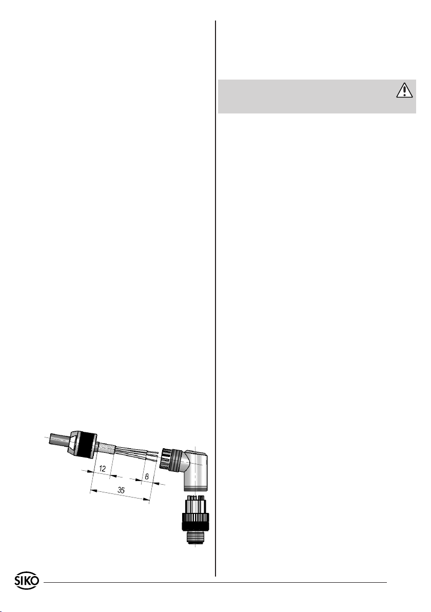
Gegenstecker gewinkelt (5-pol.)
Bei SIKO als Zubehör unter Art.Nr. 82804 (Profibus
IN 5-pol.) erhältlich. Litzenquerschnitt der Lei-
tungen min. 0,14mm²; max. 0,5mm². Kabeldurchlass: 4-8mm.
Bei SIKO als Zubehör unter Art.Nr. 82805 (Profibus
OUT 5-pol.) erhältlich. Litzenquerschnitt der Leitungen min. 0,14mm²; max. 0,5mm². Kabeldurchlass: 4-8mm.
Bei SIKO als Zubehör unter Art.Nr. 83006 (CANo-
pen IN 5-pol.) erhältlich. Litzenquerschnitt der
Leitungen min. 0,14mm²; max. 0,5mm². Kabeldurchlass: 4-8mm.
Bei SIKO als Zubehör unter Art.Nr. 83007 (CANo-
pen OUT 5-pol.) erhältlich. Litzenquerschnitt der
Leitungen min. 0,14mm²; max. 0,5mm². Kabeldurchlass: 4-8mm.
Bei der Stecker-Montage gehen Sie bitte schrittweise vor (Abb. 17):
Druckmutter auf das Kabel fädeln.
1.
Kabel abmanteln, Schirm kürzen.
2.
Klappen Sie nun das Schirmgeflecht über den
3.
Kabelmantel nach hinten, isolieren Sie die
einzelnen Adern ca. 10mm ab und versehen Sie
Aderenden mit passenden Aderendhülsen.
Adern durch das Gehäuse fädeln und anschlie-
4.
ßen.
Klappen Sie das Schirmgeflecht wieder zurück.
5.
Nehmen Sie jetzt die Schirmfolie von dem
Papier ab und kleben Sie die Folie um das
Schirmgeflecht.
Ziehen Sie das Gehäuse bis zum Steckereinsatz
6.
und halten Sie es fest, während Sie den Steckereinsatz aufschrauben.
Drehen Sie die Druckmutter auf das Gehäuse.
7.
Ziehen Sie die Druckmutter fest.
Ändern der Winkelstellung (Abb. 17):
Buchseneinsatz aufdrehen, leicht herausziehen
1.
und in gewünschte Winkelstellung (45° Schritte)
verdrehen.
Buchseneinsatz aufschrauben.
2.
Achtung
Mehrfache Winkelverstellungen in eine Richtung,
führen zu Leitungsverkürzung und Unterbrechung.
7.1 Busabschluss-Stecker
Bei SIKO als Zubehör unter Art.Nr. 82816 (Busabschluss Profibus 5-pol.) erhältlich.
Bei SIKO als Zubehör unter Art.Nr. 82815 (Busabschluss CANopen 5-pol.) erhältlich.
Abb. 17: Gegenstecker gewinkelt
12 AG02 Datum 08.07.2010 Art.Nr. 82270 Änd. Stand 137/10
Page 13
User Information
AG02
Gear
ENGLISH
1. Warranty information
Your device has been quality controlled, tested
•
and is ready for use. Please observe all warnings
and information which are marked either directly
on the device or specified in this document.
Warranty can only be claimed for components
•
supplied by SIKO GmbH. If the system is used
together with other products, there is no warranty
for the complete system.
Repairs should be carried out only at our works.
•
If any information is missing or unclear, please
contact the SIKO sales staff.
For preservation of your warranty claims you must
•
read and understand this document fully prior to
mounting and commissioning the actuator and
observe all warnings and hints.
2. Safety information
2.1 Intended use
The actuator AG02 is intended for adjustment
tasks on equipment and machinery for industrial applications and must never be used for other
purposes.
Conversion or alteration of the device not approved
•
by SIKO is forbidden for safety reasons.
Observe the operation and installation instructions
•
specified in this User Information.
Refrain from any operation that may compromise
•
safety with the device.
Observe the prescribed safety information con-
•
tained in this user information.
2.2 Mounting, commissioning and operating
staff
Mounting, commissioning, operating and maintenance must only be performed by expert personnel
authorized by the plant operator.
2.3 Identification of dangers and notes
Safety notes consist of a signal sign and a signal
word.
2.3.1 Signal words
"Danger"
Indication of dangers that may cause grievous bodily harm resulting in death, property damage or
unplanned reactions of devices.
"Warning"
Indication of dangers that may be capable of causing bodily harm, property damage or unplanned
reactions of devices.
"Caution"
Indication of dangers that may be capable of causing property damage or unplanned reactions of
devices.
"Attention"
Important notes that facilitate operation or are
capable of causing property damage or unplanned
reactions of devices if not complied with.
2.3.2 Signal signs
2.4 General safety notes
Danger: Danger of injury when used in hazardous areas
Do not use the actuator in hazardous areas.
•
Danger: Danger of injury by unbraked drive
Power failure, faults and actions resulting in the
•
activation of the output stage cause immediate
loss of torque.
Make sure that this danger will be prevented
•
by means of an external fixture (e.g. holding
brake) if required.
AG02 Datum 08.07.2010 Art.Nr. 82270 Änd. Stand 137/10 13
Page 14
N
S
Warning: Danger of injury by rotating parts
Clamping ring and hollow shaft are rotating parts
•
capable of causing hazards including bruises,
friction or catching.
Install appropriate guards to prevent persons from
•
accessing such parts.
Warning: Danger of burning
During operation, temperatures >60°C may de-
•
velop on the surface of the housing .
Install appropriate guards to prevent persons from
•
accessing the housing and protect temperaturesensitive parts of the equipment.
Caution: Generator operation
With high centrifugal mass on the output side, the
•
drive can change to generator operation during
braking. Mechanical energy is converted into
electrical energy leading to an immediate rise
in intermediate circuit voltage since the drive is
unable to recover energy.
Reduce travel speed or acceleration immediately
•
after the first occurrence of the error "Intermediate
circuit overvoltage".
Caution: Interference by external magnets
Protect the drive from the influences of external
•
magnets.
Warning: Loss of the type of protection
Radial shaft sealings are subject to wear! Protection class therefore depends on life and condition
of sealings.
Mounting instructions
Please handle the gear carefully.
Especially do not:
disassemble or open the gear (unless stipulated
•
in this brochure).
knock on casing or shaft; the gear's inner compo-
•
nents (e.g. the coded disk) could be damaged.
mechanically work on the gear (drilling, milling,
•
etc.), which would cause serious damage.
apply inadmissible axial or radial load on the
•
shaft or overload the gear.
mount the gear incorrectly.
•
Otherwise manufacturer's warranty will be invalidated!
Fig. 1: Mounting instructions
Mounting of the gear
Mounting is via torque bracing (bracket, see fig.
•
2) and clamping of the shaft. Mount the gear with
as little tension as possible. In order to achieve
backlash-free radial fixation, we recommend to
3. Identification
Please check the particular type of unit and type
number from the identification plate. Type number
and the corresponding version are indicated in the
delivery documentation.
e.g. AG02-0023
version number
type of unit
use the elastomer clamp bushing on the mounting bracket.
Entirely slide the spring collet into the mounting
•
bore (see fig 2) and then tighten it.
Forces must not be transmitted via the housing,
•
but only via the shaft.
Take care that there is no large angle and that
•
there is a parallel offset between shaft and flanging-on surface. In case of incorrect positioning
4. Installation
For mounting, the degree of protection specified
must be observed. If necessary, protect the unit
tensions develop in the bearing that may lead
to increased heating and thus to destruction of
the bearings.
against environmental influences such as sprayed
water, dust, knocks, extreme temperatures.
14 AG02 Datum 08.07.2010 Art.Nr. 82270 Änd. Stand 137/10
Page 15
0
10
20
30 40
50
60 70 80
0
Caution: shaft length
Length "L" of the customer's machine shaft must be max.
40mm if the actuator has ratio 55 and max. 50mm if the
actuator is with ratio 62 (only relevant for actuator with
shaft type "S"). Our recommendation for the customer's
machine shaft: ø14f8
elastomer
clamp bushing
bracket
Fig. 2: Mounting options
Via the clamping ring or keyway (see fig. 3) the
•
driving torque is transferred onto the driving
shaft.
claming ring
grub screw
Attention: Interference resistance
All connections are protected against the effects
•
of interference. The location should be selec-
ted to ensure that no capacitive or inductive
interferences can affect the encoder or the
connection lines!
Suitable wiring layout and choice of cable can
•
minimise the effects of interference.
Necessary measures:
Only screened cable should be used. Screen should
•
be connected to earth at both ends.
Wiring to the screen and ground (0V) must be
•
secured to a good point.
The system should be positioned well away from
•
cables with interference; if necessary a protective
screen or metal housing must be provided. The
running of wiring parallel to the mains supply
should be avoided.
Contactor coils must be linked with spark sup-
•
pression.
Caution: EMC
Following actions are needed to guarantee the
•
actuator electromagnetic compatibility (only
for encoder: magnetic absolute ABM):
The retractable ferrite (supplied with the actuator)
•
is to be attached to the supply line near the 3pole connector.
The drive is to earthed via the flat connection
•
with a strand section of at least 4mm².
Power supply
mounting only admissable
with mounted shaft
Hollow shaft with
keyway DIN 6885/1
Fig. 3: Driving shaft mounting
5. Electrical connection
Warning
Switch power off before any plug is inserted or
•
removed!
Attention
Any wiring must only be carried out without
•
power.
Provide stranded wires with ferrules.
•
Check all lines and connections before switching
•
on the equipment.
The gear's and follower electronic's (e.g. control
•
unit) operating supply must be switched on
simultaneously.
AG02 Datum 08.07.2010 Art.Nr. 82270 Änd. Stand 137/10 15
The power supply of the actuator should be dimensioned sufficiently, since power consumption
may transiently be as high as 6A (150W motor) or
3A (70W motor). Therefore, the wire cross-section
for the actuator must be at least 0,5mm². Supply
voltage depends on the unit type and is indicated
in the delivery documentation and on the identification plate.
Danger: Overload
For fusing the drive, the customer must provide
a fuse in addition to internal current limitation
(max. current load - see "Power consumption")
(not for encoder: magnetic absolute)!
Motor : 0...24VDC
Incremental encoder OP/LD24 : 24 VDC ±20%
Incremental encoder LD5 : 5 VDC ±5%
Resolution increm. encoder : 1000 pulses/rev.
Resolution abs. encoder : 1600 pulses/rev.
Page 16
Potentiometer with : 12...28 VDC
R/I transformer (MWI) or R/U transformer (MWU)
Power consumption
Incremental encoder OP/LD24 : < 25mA
Incremental encoder LD5 : < 50mA
Controller electronics unit : < 150mA (incr.)
Controller electronics unit : < 170mA (absolute
magnetic)
motor max. current charge
short time operation S2; 25%ED
motor (150W) 5,8A
Motor (70W) 3A for i = 55,3 / 62,2
2,1A for i = 135,8
Short-time operation S2 (excerpt from the stipula-
tions accord. to DIN 57530, VDE 0530, part 1)
Operation at constant load during a limited, de-
fined period (t on) with following pause (t off)
until the motor has reached ambient temperature
again.
Example: t on off
< 2,5s > 7,5s
< 2,5min > 7,5min
5.1 Pin assignment
Inkremental encoder (OP/LD24) 12 pole plug pin:
PIN Designation
A Signal /B
B N.C.
C Signal /I
D Signal I
E Signal A
F Signal /A
G N.C.
H Signal B
viewing side =
plug-in side
J N.C.
K GND
L N.C.
M +UB (with polarity pro-
tection)
Inkremental encoder (LD5) 12 pole plug pin:
PIN Designation
A Signal /B
B +SUB (Sensor)
C Signal /I
D Signal I
E Signal A
F Signal /A
G N.C.
H Signal B
J N.C.
K GND
L SGND (Sensor)
}*
*
viewing side =
plug-in side
M +UB
* internally linked
Potentiometer without instrument transformer
(P10) 7 pole plug pin:
PIN Designation
1 Pe End point
2 Po Start point
3 S Moving contact
4-7 N.C.
viewing side =
plug-in side
Potentiometer with R/I transformer (MWI) 7
pole plug pin:
PIN Designation
1 I2 I+
3-7 N.C.
viewing side =
plug-in side
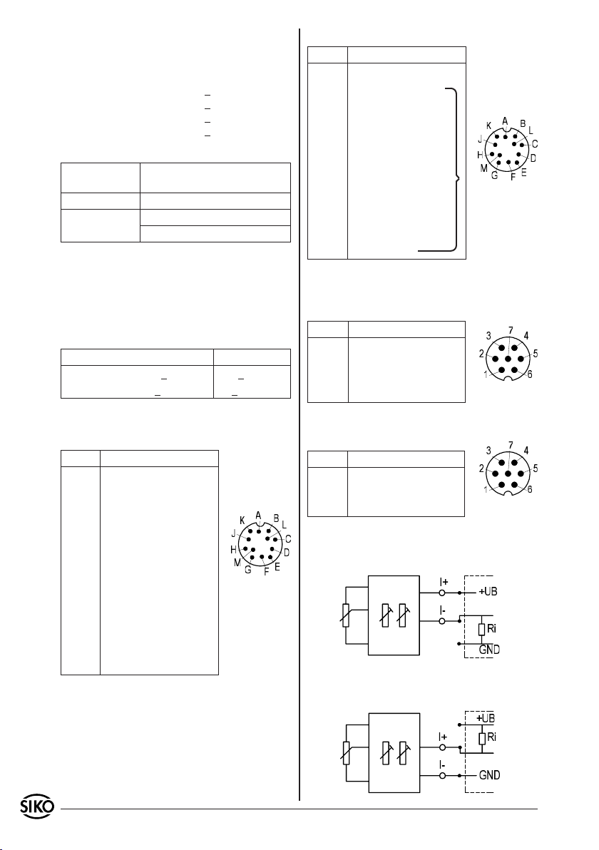
Connection instrument transformer (MWI) load
against mass:
follower electronics
Connection instrument transformer (MWI) load
against +UB:
follower electronics
16 AG02 Datum 08.07.2010 Art.Nr. 82270 Änd. Stand 137/10
Page 17
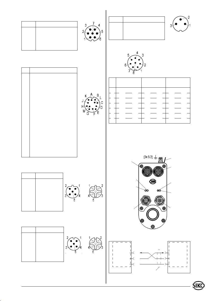
Potentiometer with R/U transformer (MWU) 7
pole plug pin:
PIN Designation
1 GND
2 +24VDC
3 Uout
4-7 N.C.
viewing side =
plug-in side
Motor / network 3 pole plug pin:
PIN Designation
1 +M / +UB
2 N.C.
3 -M / GND
viewing side =
plug-in side
Motor control inputs PWM 8 pole plug pin:
Control signals/interface (absolute magnetic)
12 pole plug pin:
PIN Designation
A ES1
B ES2
limit switch 1;
24VDC±20%
limit switch 2;
24VDC±20%
C Enable 24VDC±20%
D N.C.
E +24VDC
F N.C.
G RXD/DÜA RS232/RS485
Output
max. 200mA
viewing side =
plug-in side
H TXD/DÜB RS232/RS485
J GND interface
K GND
L CAL
limit switch 1+2;
enable; CAL
calibration switch;
24VDC±20%
M GND see chapter 4.6
Profibus-DP (PB) Bus In 5 pole plug pin, Bus Out
5 pole socket contact (absolute magnetic):
PIN Designation
1 +5VDC for termi-
nating resistors
Bus In Bus Out
2 BUS A
3 GND
4 BUS B
viewing side = plug-in side
5 N.C.
CANopen (CAN) Bus In 5 pole plug pin, Bus Out 5
pole socket contact (absolut magnetic):
PIN Designation
1 N.C.
Bus In Bus Out
2 N.C.
3 GND
4 CAN_H
viewing side = plug-in side
5 CAN_L
viewing side =
plug-in side
PIN Version Digital Version Analog
unipolar
1 right motion plus enable plus enable plus
2 right motion ground enable ground enable ground
3 left motion plus right/left plus N.C.
4 left motion ground right/left ground N.C.
5 fast/creep motion analogue 0...+10V analogue -10...+10V
6 fast/creep motion analogue ground analogue ground
7+8 N.C. N.C. N.C.
Version Analog
bipolar
5.2 Interface connection (RS232/RS485) (only
magnetic absolute)
The serial RS232 or RS485 interface is connected
via 12-pin connector (fig. 4).
limit switch,
interface,
calibration switch,
enable
green: limit switch 1
green: limit switch 2
Bus IN
PE
Network
red: fault or
enable inactive
yellow: profibus (optional)
Bus OUT
Fig. 4: Connections AG02
In ter face
RS232
AG02
RXD
TXD
GND
(G)
(H)
(J)
Apply screen to PE
Int erface
RS232
RXD
TXD
GND
PC
Fig. 5: Pinout scheme RS232 interface
AG02 Datum 08.07.2010 Art.Nr. 82270 Änd. Stand 137/10 17
Page 18
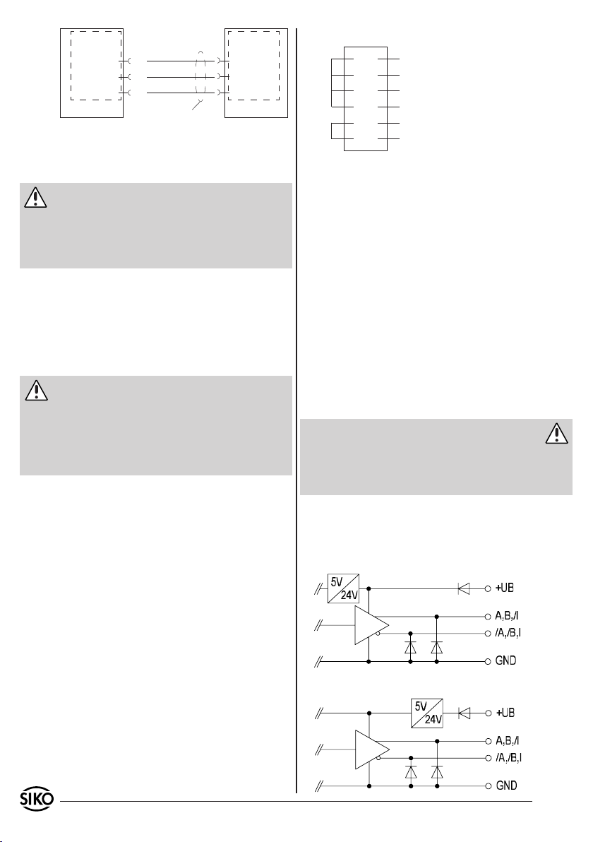
Interface
RS485
AG02
DÜA
DÜB
GND
(G)
(H)
(J)
Apply screen to PE
Inte rface
RS485
DÜA
DÜB
GND
PC
Fig. 6: Pinout scheme RS485 interface
5.3 Calibration switch connection (only magnetic
absolute)
Attention
The calibration switch is connected via the 12pin connector. The input operates high-active,
which means that calibration of the actuator is
performed upon applying of 24VDC to the device's
+ input.
The input of the calibration switch is optodecoupled.
5.4 Limit switch / enable connection (only with
magnetic absolute encoder)
Case 1: with limit switch and enable
Attention
The two limit switches and the enable are connected via the 12-pin connector. With the limit
switch deactivated, a 24VDC voltage must be applied on the +input. For the drive to be moved,
a 24VDC voltage must be applied on the Enable
input as well.
These 24VDC can on demand be drawn from the
clips Pin "E" and "M". This allows an economic
wiring.
Please note that the galvanic separation between
the unit supply and the control input is in this
case nonexistent.
The inputs of the limit switches or enable, resp.,
are opto-decoupled.
Suggestion to PIN-bridging:
E
A
B
C
K
M
24V output
Limit switch 1 ES1 (24V)
Limit switch 2 ES2 (24V)
Enable (24V)
GND ES
GND
If limit switch 1 or limit switch 2 is inactive, this
is signalled by a green LED (see fig. 4). If enable
inactive, this is signalled by a red LED (see fig.
4).
6. Commissioning
Please carefully read the information on the gear's
mechanical and electrical connection. This will
ensure a trouble free commissioning and operation.
Before operation, please check again:
that the supply voltage's polarity is correct.
•
correct connection of cable and signal lines
•
secure gear fixation on the hollow shaft.
•
correct mounting and functioning of the limit
•
switches.
Warning: latch-up effects
The unit's and follower electronic's (e.g. control
unit) operating supply must be switched on simultaneoulsy to avoid latch-up effects on the unit's
outputs (only by incremental encoder).
6.1 Incremental encoder
Output circuits
OP (Push-Pull), differential
Case 2: without limit switch and enable
If no limit switches or enable are required, 24VDC
must be applied permanently to the inputs of the
limit switches or enable!
LD24 Line Driver, differential
18 AG02 Datum 08.07.2010 Art.Nr. 82270 Änd. Stand 137/10
Page 19
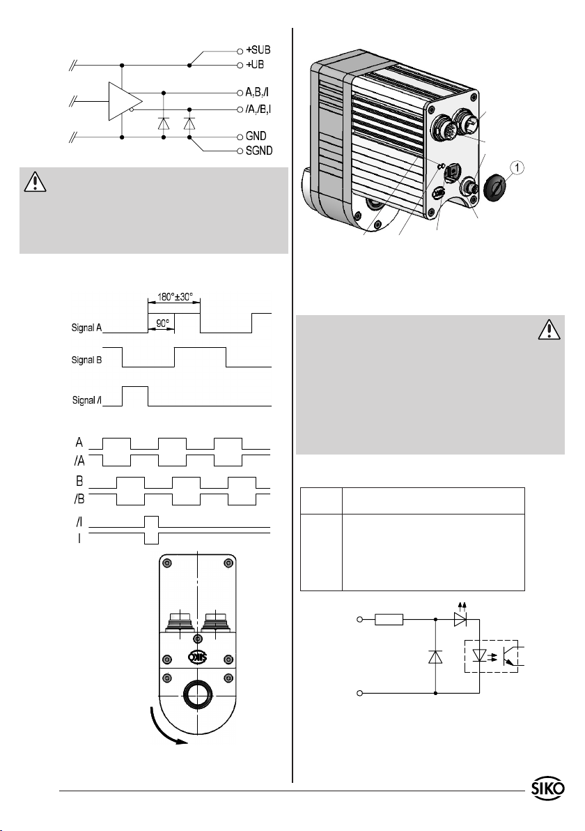
LD5 Line Driver, differential
Caution: LD24, LD5
The encoder outputs correspond to RS422A. Its
outputs can drive a load of up to 70mA, are shortcircuit-proofed and have a thermic de-energization. The load per channel must not exceed 35mA
by using all channels.
6.2 Motor control PWM
LED 1+2LED 3+4
Network
Encoder
Inputs
P2 (only digital)
P1 (only digital)
Output signals / Wave form
Fig. 7: Tolerance range of the output channels
Potentiometer setup
After removing the covers (1), potentiometers P1
and P2 are accesible.
Warning
Due to the type of protection, only the covers
•
(1) may be loosened.
With the cover (1) loosened, the drive's type of
•
protection is no longer ensured.
Set the parameters on the trimming potentiome-
•
ters using a 2mm slot screwdriver.
When remounting the screws (1) take care that
•
the seal are seated correctly!
Only with digital inputs:
Potenti-
Description
ometer
P1 Speed setting in fast motion; PWM conti-
nuously adjustable 0 to 100% (left stop 0%;
right stop 100%). Active fast/slow input.
P2 Speed setting in fast motion; PWM conti-
nuously adjustable 0 to 100% (left stop 0%;
right stop 100%). Inactive fast/slow input.
right motion+
left motion+
fast/creep mation+
right motionleft motion-
Turning value e;
when mounted
A before B
fast/creep mation-
Fig. 9: Input circuit/digital inputs
Fig. 8: Wave form
AG02 Datum 08.07.2010 Art.Nr. 82270 Änd. Stand 137/10 19
Page 20
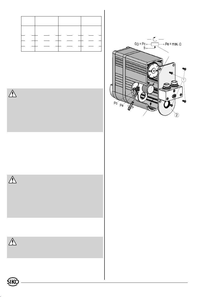
Displays:
LED Digital Analogue
1,yellow blinking
600ms= Start Up
2, blue right enable enable
3, blue left right/left N.C.
4,yellow fast/creep N.C. N.C.
unipolar
blinking
300ms=Current
Analogue
bipolar
error,
On=operation
6.3 Encoder with potentiometer with or without
transformer
6.3.1 Potentiometer setting (P10)
When correctly connected and switched on, the
unit displays show the current actual value.
Attention: turning direction
The measuring range is a result of the transmission
of potentiometer's gear. We deliver the potentiometer with the left turning direction (see fig. 10).
To check the turning direction take a measurement
of the resistance value between 'Po' and 'S'.
R = 0 Ohm: turning direction i
R = max. value: turning direction e
6.3.2 Setting and alignment of the R/I transformer (MWI)
If the device is equipped with a resistance-current
converter, then the potentiometer resistance is
converted into a current of 4...20mA. The measuring current is also used for feeding the instrument transformer.
Attention: turning direction
Ex works, the instrument transformer is aligned to
default values: 4mA for the start position (Po) and
20mA for the end position (Pe) of the potentiometer. To check the turning direction take a measurement of the current value between 'I+' and 'I-'.
Current I = 4mA: truning direction e
Current I = 20mA: turning direction i
This measuring range corresponds to the transmission range of the potentiometer wich is given by
the customer.
Attention: trimmpotentiometer's
Via two trimmpotentiometer's Po and Pe (see
fig. 10) these values can be adjusted to the
application's actual start and end position.
6.3.2.1 Setting the instrument transformer
(MWI)
When the screws (1) are removed and the cover
(2) opened, the trimming potentiometers can be
accessed.
Potentiometer
Turning direction from driving shaft after turning on
Fig. 10: Setting the trimming potentiometers MWI
Trimmpotentiometer's Po is used to adjust a
•
current of 4mA to potentiometer values of 0 to
15% of the total range.
Trimmpotentiometer's Pe is used to adjust a
•
current of 20mA to potentiometer values of 90
to 100% of the total range.
The smallest available potentiometer range, in
which 4 to 20mA are delivered, is hence 15% to
90% of the potentiometer's resistance range.
6.3.2.2 Alignment the instrument transformer
(MWI)
Drive the machine to the start position before
1.
mounting of the actuator.
- By using of the clamp ring: Mount and fix the
2.
actuator (see fig. 3).
- By using of key way: Push the actuator to the
stop and turn until the torque pin can be put
in the desired position (see fig. 2). Gear has to
be locked with the thread screw.
Turn trimmpotentiometer Po until start value
3.
(4mA) is measured.
Move axis to end position.
4.
Turn trimmpotentiometer Pe until end value
5.
(20mA) is measured.
Mount the housing cover.
6.
The steps 3 to 5 are to be repeated until the values are balanced.
20 AG02 Datum 08.07.2010 Art.Nr. 82270 Änd. Stand 137/10
Page 21
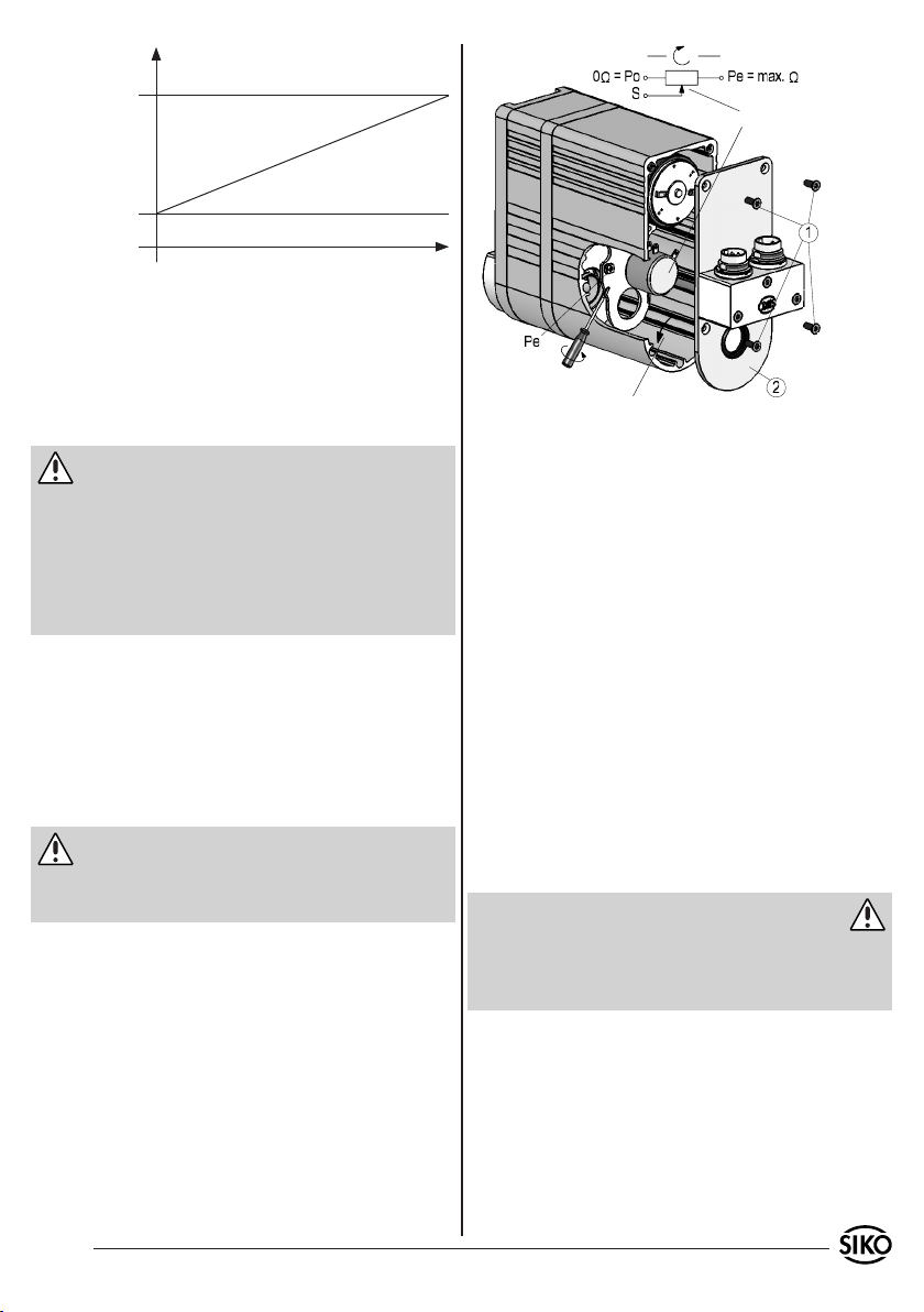
Output
current
20mA
4mA (Po)
(Pe)
Potentiometer
0
Distance
Fig. 11: Alignment
6.3.3 Setting and alignment of the R/U transformer (MWU)
If the device is equipped with a resistance-voltage converter, then the potentiometer resistance is
converted into a voltage of 0 to 10VDC. Connection is via three-wire technology.
Attention: turning direction
Ex works, the instrument transformer is aligned to
the initial value of 0V and a final value of 10V output voltage (Pe). To check the turning direction
take a measurement of the voltage value between
'GND' and 'Uout':
Voltage U = 0V: turning direction e
Voltage U = 10V: turning direction i
This measuring range corresponds to the transmission range of the potentiometer which is given
by the customer. The output of the instrument
transformer should be wired against GND with a
resistor 2 to 10KΩ to enable the initial value of
0V to be set. However, the output load should be
dimensioned so that an output current of 15mA
won't be exceeded in the end position (10V).
Attention: trimmpotentiometer's
By means of the trimming potentiometer (see fig.
12), the final value can be adjusted to the actual
final position of the application.
6.3.3.1 Setting the instrument transformer (MWU)
When the screws (1) are removed and the cover
(2) opened, the trimming potentiometers can be
accessed.
Turning direction from driving shaft after turning on
Fig. 12: Setting the trimming potentiometers MWU
Trimmpotentiometer Pe is used to adjust a voltage
•
of 10V to potentiometer values of 60 to 100%
of the total range.
6.3.3.2 Alignment the instrument transformer
(MWU)
Move axis to final position
1.
Turn potentiometer (Pe) until an output voltage
2.
of (10V) is measured.
6.4 Magnetic absolute encoder (Profibus-DP;
CANopen; serial interfaces)
After correct mounting and wiring, the actuator
can be activated by turning on the 24V power supply. Green lighting of the two LED's signals that
no limit switches are active (see fig. 4). Now, the
standard protocol enables customized parameterization of the actuator via the serial RS232 or
RS485 interface.
Warning
Prior to commissioning the drive, thoroughly
read the manuals. The manuals for Profibus-DP,
CANopen and serial interfaces can be found on
the attached CD.
AG02 Datum 08.07.2010 Art.Nr. 82270 Änd. Stand 137/10 21
Page 22
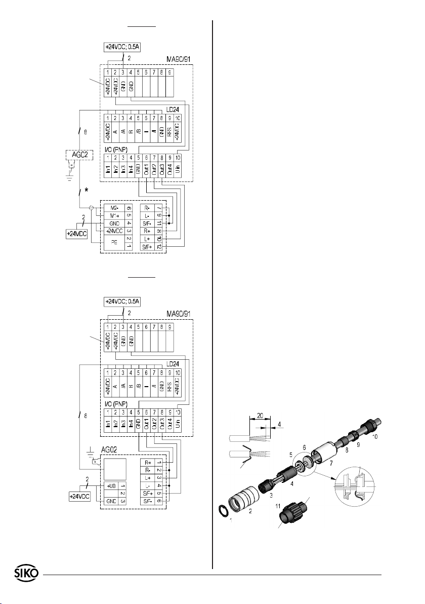
Application example of external motor control
MS02 -> AG02 -> MA90 (I/O PNP)
supply
supply
encoder
motor
MS02
(digital input)
supply
Application example of internal motor control
PWM, AG02 (nur Digital) -> MA90 (I/O PNP)
supply
supply
encoder
7. Accessory connector
Straight mating connector (Incremental encoder,
Potentiometer, Motor)
12-pole connector (Incremental encoder) Available
from SIKO as accessory art. no. 76572. Wire cross
section is to be at least 0,14mm², max. 0,25mm².
Cable channel: 6-8mm.
7-pole connector (Potentiometer) Available from
SIKO as accessory art. no. 76141. Wire cross section is to be at least 0,14mm², max. 0,5mm². Cable channel: 4-6mm.
3-pole connector (Motor) Available from SIKO as
accessory art. no. 82182. Wire cross section is to
be at least 2x0,75mm². Cable channel: 4-6mm.
Please proceed as follows (fig. 13):
Slip parts 6 to 10 over outer cable.
1.
Strip cable.
2.
Turn down screening.
3.
Push shielding ring (5) onto ferrules.
4.
Solder stranded wires at insert (3) (follow
5.
connection diagram).
Open spacer (spacer sleeve 4) and put it over
6.
ferrules, squeeze and push it onto insert (3). Slot
and keyway of parts 3 and 4 must align.
Press shield-clamping ring (6) and shielding ring
7.
(5) together; cut prodruding screening.
Push ring nut (2) and coupling sleeve (7)
8.
together and screw assembly tool (11) using
appropriate tool.
Push sealing ring (8) into pinch ring (9) and
9.
slide both parts into coupling sleeve (7).
Screw pressing screw (10) and coupling sleeve
10.
(7) together.
Push sealing ring (1) into ring nut (2).
11.
screening
supply
Geber
screening
socket
pin
Fig. 13: Straight mating connector
22 AG02 Datum 08.07.2010 Art.Nr. 82270 Änd. Stand 137/10
Page 23
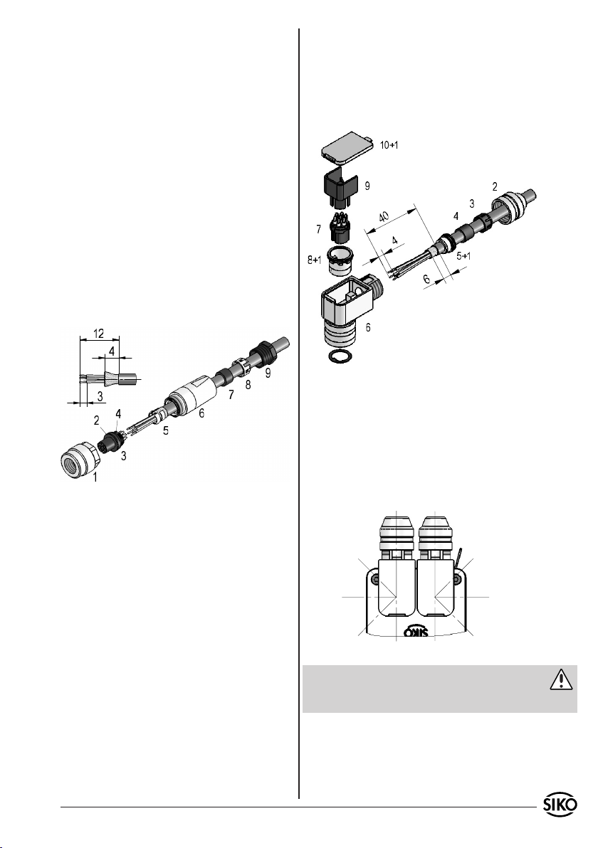
Straight mating connector (8 pole Inputs PWM)
8-pole connector (Inputs PWM) Available from
SIKO as accessory art. no. 81351. Wire cross section is to be at least max. 0,14mm². Cable channel: max. 5mm.
Please proceed as follows (fig. 14):
Mount seals (2 & 4) on female contact (3).
1.
Stringing Pressing screw (9), pinch ring (8),
2.
Solder wires on insert (7).
7.
Mount positioning sleeve (8) in angled po-
8.
sition.
Set in insert (7) and distance sleeve (9).
9.
Mount cover (10).
10.
Fix pressing screw (2) (approx. 10-20Ncm).
11.
seal (7) and snap bushing (6).
Turn on the pressing screw (9) very slightly.
3.
Dismantle cable, strip and tin conductor.
4.
Shorten and turn down screen.
5.
Fit screen collar (5) to cable diameter, then clip
6.
it on and solder it so the screen.
Solder and insert female contact (3) (after
7.
releasing pressure screw (9)).
Mount connection ring (1).
8.
Fix pressing srew (9).
9.
Fig. 15: Right angle mating connector
Changing the angle position (fig. 15 + 16):
Slightly unscrew pressing screw (6).
1.
Remove ring nut (8).
2.
Slightly pull out female contact (7) and rotate to
3.
desired angular position (in steps of 45°).
Mount female contact; tighten ring nut and
Fig. 14: Straight mating connector
4.
pressure screw.
Right angle mating connector (3 pole; 12 pole)
12-pole connector (Incremental encoder) Available
from SIKO as accessory art. no. 79666. Wire cross
section is to be at least 0,14mm², max. 0,25mm².
Cable channel: 6-8mm.
3-pole connector (Motor) Available from SIKO as
accessory art. no. 81363. Wire cross section is to
be at least 2x0,75mm². Cable channel: 4-6mm.
Please proceed as follows (fig. 15):
Mount seals (1) (3x).
1.
Stringing pressing screw (2), pinch ring (3),
2.
seal (4), shielding ring (5).
Dismantle cable, shorten screening, strip and
3.
tin conductor.
Thread-up wires thruogh the housing (6).
4.
Mount shielding ring (5) and pinch ring (3).
5.
Turn on the pressing screw (2) very slightly.
6.
Fig. 16: Possible angle positions
Attention
Multiple angle adjustments to a single direction
cause shortening of the line and break.
Right angle mating connector (5 pole)
5-pole connector (profibus-DP IN) Available from
SIKO as accessory art. no. 82804. Wire cross section is to be at least 0,14mm², max. 0,5mm². Cable channel: 4-8mm.
AG02 Datum 08.07.2010 Art.Nr. 82270 Änd. Stand 137/10 23
Page 24
5-pole connector (profibus-DP OUT) Available from
SIKO as accessory art. no. 82805. Wire cross section is to be at least 0,14mm², max. 0,5mm². Cable channel: 4-8mm.
5-pole connector (CANopen IN) Available from
SIKO as accessory art. no. 83006. Wire cross section is to be at least 0,14mm², max. 0,5mm². Cable channel: 4-8mm.
5-pole connector (CANopen OUT) Available from
SIKO as accessory art. no. 83007. Wire cross section is to be at least 0,14mm², max. 0,5mm². Cable channel: 4-8mm.
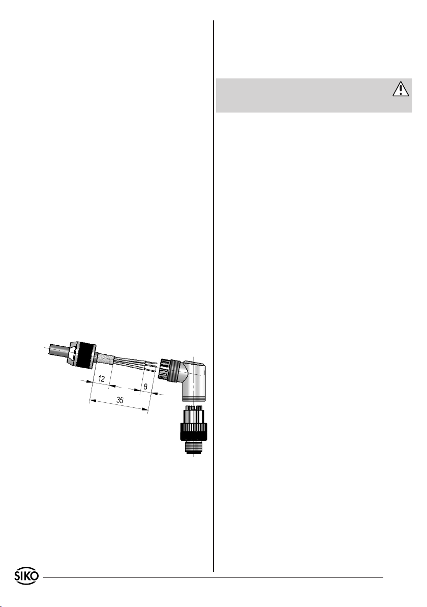
Please proceed as follows (fig. 17):
Thread pressure nut onto the cable.
1.
Strip the cable sheath, shorten the screen.
2.
Fold the screen sheath about the cable sheath
3.
back, dismantle the single wires (approx. 10mm)
and provide wire ends with suitable wire end
ferrule.
Thread cores through the housing and con-
4.
nect.
Fold the screen sheath back. Take the screen
5.
foil from the paper and stick the foil around
the screen sheath.
Pull the case up to the plug application and
6.
hold on it, while you screw on the plug application.
Turn the pressure nut on the case. Tighten the
7.
pressure nut.
Changing the angle position (fig. 17):
Turn on female contact, slightly pull out and
1.
rotate to desired angular position (in steps
of 45°).
Screw on female contact.
2.
Attention
Multiple angle adjustments to a single direction
cause shortening of the line and break.
7.1 Bus terminator
5-pole connector (bus terminator profibus) Available from SIKO as accessory art. no. 82816.
5-pole connector (bus terminator CANopen) Available from SIKO as accessory art. no. 82815.
Fig. 17: Right angle mating connector
SIKO GmbH
Werk / Factory:
Weihermattenweg 2
79256 Buchenbach-Unteribental
Postanschrift / Postal address:
Postfach 1106
79195 Kirchzarten
Telefon/Phone +49 7661 394-0
Telefax/Fax +49 7661 394-388
E-Mail [email protected]
Internet www.siko.de
Service [email protected]
24 AG02 Datum 08.07.2010 Art.Nr. 82270 Änd. Stand 137/10
 Loading...