

Page 1
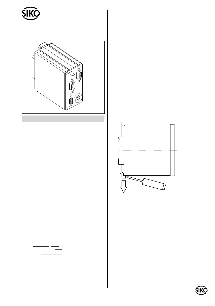
Benutzerinformation
AEA111/1
Als Ausgänge stehen eine RS-485-Schnittstelle
(zur Geräteparametierug bzw. zur Realisierung
des SIKONETZ3-Protokolls (SN3)), die SSI-Schnittstelle und ein 1VSS Analogausgang (sin/cos) zur
Verfügung.
Auswerteelektronik
4. Mechanische Montage
Die Montage darf nur gemäß der angegebenen IPSchutzart vorgenommen werden. Das System muss
ggfs. zusätzlich gegen schädliche Umwelteinflüsse, wie z.B. Spritzwasser, Lösungsmittel, Staub,
Schläge, Vibrationen, starke Temperaturschwankungen geschützt werden.
4.1 Montage Auswerteelektronik
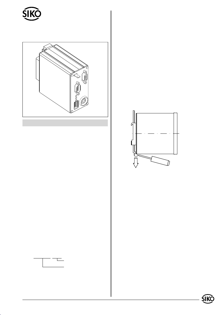
Die AEA111/1 ist zum Anbau an eine Hutschiene
35x7,5 nach DIN 50022 vorgesehen. Zur Montage
ist der Halter auf die Hutschiene aufzuschnapppen
und darauf zu achten, dass sich die Verriegelung
unten befindet. Zur Demontage wird der Riegel
nach unten bewegt.
DEUTSCH
1. Gewährleistungshinweise
Lesen Sie vor der Montage und der Inbetriebnahme
•
dieses Dokument sorgfältig durch. Beachten Sie zu
Ihrer eigenen Sicherheit und der Betriebssicherheit
alle Warnungen und Hinweise.
Ihr Produkt hat unser Werk in geprüftem und be-
•
triebsbereitem Zustand verlassen. Für den Betrieb
gelten die angegebenen Spezifikationen und die
Angaben auf dem Typenschild als Bedingung.
Garantieansprüche gelten nur für Produkte der
•
Firma SIKO GmbH. Bei dem Einsatz in Verbindung
mit Fremdprodukten besteht für das Gesamtsystem
kein Garantieanspruch.
Reparaturen dürfen nur im Werk vorgenommen
•
werden. Für weitere Fragen steht Ihnen die Firma
SIKO GmbH gerne zur Verfügung.
2. Identifikation
Das Typenschild zeigt den Gerätetyp mit Variantennummer. Die Lieferpapiere ordnen jeder Variantennummer eine detaillierte Bestellbezeichnung zu.
z.B. AEA111/1-0023
Varianten-Nr.
Geräte-Typ
3. Kurzbeschreibung
Die AEA111/1 ist eine Auswerteelektronik, die in
Verbindung mit dem Absolutsensor MSA111 und
dem Magnetband MBA111 ein hochauflösendes
magnetisches Absolutwertmeßsystem ergibt.
AEA111/1 Datum 25.01.2008 Art.Nr. 84155 Änd. Stand 245/07 1
Abb. 1: Einbau
5. Elektrischer Anschluss
Anschlussverbindungen dürfen nicht unter
•
Spannung geschlossen oder gelöst werden!!
Verdrahtungsarbeiten dürfen nur spannungslos
•
erfolgen.
Litzen sind mit Aderendhülsen zu versehen.
•
Vor dem Einschalten sind alle Leitungsanschlüsse
•
und Steckverbindungen zu überprüfen.
Um eine störungsfreie Funktion des Gerätes si-
•
cherzustellen, ist der fachgerechte Anschluss an
den Potentialausgleich unbedingt erforderlich.
Um dies sicherzustellen, ist an der Frontplatte der
AEA111/1 ein Anschluss für 6,3mm Flachstecker
vorhanden. Der Anschluss sollte so kurz wie
möglich ausgeführt werden.
Page 2
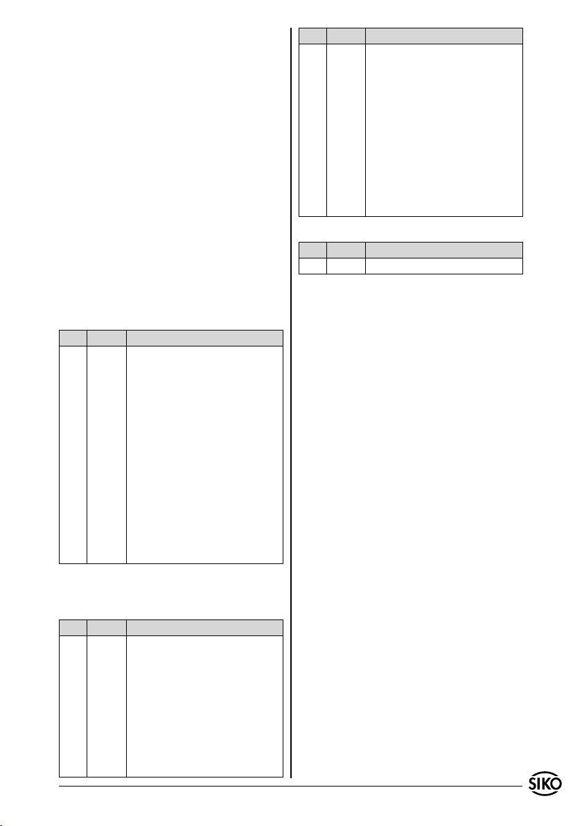
6
9
1
6
9
1
6
5
1
5
1
2
3
Hinweise zur Störsicherheit
Alle Anschlüsse sind gegen äußere Störeinflüsse
geschützt. Der Einsatzort ist aber so zu wählen,
dass induktive oder kapazitive Störungen nicht
auf den Magnetsensor, die Auswerteelektronik
oder deren Anschlussleitungen einwirken können! Durch geeignete Kabelführung und Verdrah-
tung müssen Störeinflüsse (z.B. von Schaltnetzteilen, Motoren, getakteten Reglern oder Schützen)
vermindert werden.
Erforderliche Maßnahmen:
Nur geschirmtes Kabel verwenden. Den Kabel-
•
schirm beidseitig auflegen. Litzenquerschnitt der
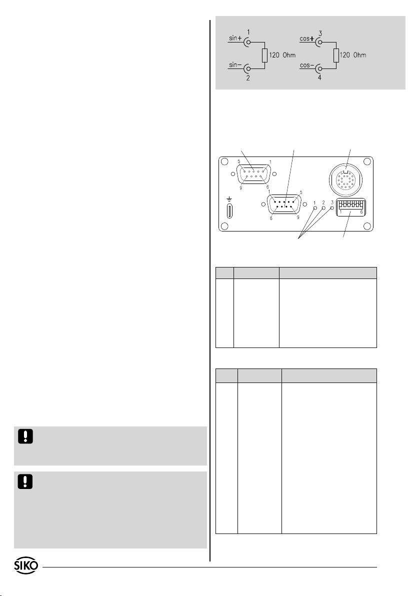
5.1.1 Anschlussbelegung EA
Die Ausgangssignale und die Versorgungsspannung
werden jeweils über eine 9-polige D-SUB-Steckverbindung geführt.
X1/Ausgang
X2/Schnittstelle
Leitungen 0,25 mm².
Die Verdrahtung von Abschirmung und Masse
•
(GND) muss sternförmig und großflächig erfolgen.
Der Anschluss der Abschirmung an den Potentialausgleich muss großflächig (niederimpedant)
erfolgen.
Das System muss in möglichst großem Abstand von
•
Leitungen eingebaut werden, die mit Störungen
belastet sind; ggfs. sind zusätzliche Maßnahmen
wie Schirmbleche oder metallisierte Gehäuse
vorzusehen. Leitungsführungen parallel zu Energieleitungen vermeiden.
Schützspulen müssen mit Funkenlöschgliedern
•
beschaltet sein.
Um die Störfestigkeit der AEA111/1 zu erhöhen,
•
ist es notwendig, die Anschlussleitung für die
Versorgungsspannung und Ausgangssignale mit
einer Ferrit-Hülse zu versehen, die in möglichst
geringem Abstand zu der D-SUB Steckverbindung
montiert werden sollte. Da der Außendurchmesser
von der Art der verwendeten Anschlussleitung
abhängt, sollte die Hülse möglichst passgerecht
ausgewählt werden.
Spannungsversorgung: 24VDC ±20%
Leistungsaufnahme: < 8 Watt
Status LED
Anschlussbelegung Ausgang X1 (9-polig)
PIN Signal Beschreibung
1 sin+ Positiver Sinus Ausgang
2 sin- Negativer Sinus Ausgang
3 cos+ Negativer Cosinus Ausgang
4 cos- Positiver Cosinus Ausgang
5 Analog_GND Masse Analogsignale
6-9 - n.c.
Schnittstelle X2
PIN Signal Beschreibung
1 +24VDC Versorgungsspannung, Aus-
werteelektronik
SW1/Parameter
2 SSI Takt+ SSI-Takteingang, optoent-
5.1 Anschlussbelegung
Achtung! Um eine stabile elektrische Verbindung
zu gewährleisten, ist es erforderlich, die D-SUB-
3 RS485 DÜA Serielle Service-Schnittstelle
4 Ext_Config Externer Konfigurations-
Steckverbindung mit der zugehörigen Schraubverriegelung zu fixieren.
Achtung! Falls die analogen Ausgangssignale
nicht weiterverarbeitet werden, wird empfohlen,
5 GND Masse Auswerteelektronik
6 SSI Daten+ SSI-Datenausgang
7 SSI Takt- SSI-Takteingang, optogekop-
die Ausgänge sin+ und sin- sowie cos+ und cosjeweils mit einem Widerstand von 120 Ohm anzuschließen.
Bei Weiterverarbeitung der Analogsignale ist bei
der Empfangselektronik darauf zu achten, dass
diese den Abschlusswiderstand beinhaltet.
2 AEA111/1 Datum 25.01.2008 Art.Nr. 84155 Änd. Stand 245/07
8 RS485 DÜB Serielle Service Schnittstel-
9 SSI Daten- SSI Datenausgang
koppelt
eingang (siehe Kap. 9, 12)
pelt
le
Sensor
Page 3
1
5
9
1
2
6
3
1
9
5
1
2
1
3
6
8
1
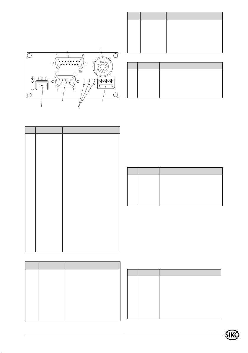
5.1.2 Anschlussbelegung EB
Die Ausgangssignale werden über eine 9-polige und/oder 15-polige D-SUB-Steckverbindung
und die Versorgungsspannung über eine 3-polige
Steckverbindung geführt.
X1/Ausgang
Sensor
PIN Signal Beschreibung
6 SSI Daten+ SSI-Datenausgang
7 SSI Takt- SSI-Takteingang, optogekop-
pelt
8 RS485 DÜB Serielle Service-Schnittstelle
9 SSI Daten- SSI Datenausgang
X4 Betriebsspannung
PIN Signal Beschreibung
1 +24VDC Versorgungsspannung, Aus-
werteelektronik
2 GND Masse Auswerteelektronik
3 Ext_Config Externer Konfigurationseingang
X3/Schnittstelle
X4/Betriebsspannung
Status LED
SW1/Parameter
6. Parametereinstellungen mit SW1
Die benötigte Schnittstellen-Konfiguration muss
Anschlussbelegung Ausgang X1 (15-polig)
PIN Signal Beschreibung
1 GND Masse Auswerteelektronik
2 Ext_Config Externer Konfigurations-
eingang
3 sin- Negativer Sinus Ausgang
4 cos- Negativer Cosinus Ausgang
5 Analog_GND Masse Analogsignale
6 SSI_Takt+ SSI-Takteingang, optoent-
koppelt
7 SSI_Takt- SSI-Takteingang, optoent-
koppelt
8 sin+ Positiver Sinus Ausgang
vor dem Einschalten der Betriebsspannung mit
den entsprechenden DIP-Schaltern (SW1 siehe
Kap. 5.1) eingestellt werden, da diese nur während des Einschaltvorgangs eingelesen werden.
6.1 Betriebsart RS485 ("RS485-Mode")
(SW1.1 = OFF; Positionswertausgabe und Parametrierung über RS485)
DIP Stellung Beschreibung
1 OFF Betriebsart RS485
2 OFFONRS485 Service Standard-Protokoll
Werkseinstellung (WE)
RS485 SIKONETZ3-Protokoll
3 -- keine Funktion im RS485-Mode
9 cos+ Positiver Cosinus Ausgang
10 Digital_GND Masse Digitalsignale
11 Digital_GND Masse Digitalsignale
12 Analog_GND Masse Analogsignale
13 Analog_GND Masse Analogsignale
14 SSI_Daten- SSI Datenausgang
15 SSI_Daten+ SSI Datenausgang
Schnittstelle X3
PIN Signal Beschreibung
1 - -
6.2 Betriebsart SSI ("SSI-Mode")
(SW1.1 = ON; Positionswertausgabe erfolgt über
SSI) Die Takteingänge der SSI-Schnittstelle sind
optoentkoppelt ausgeführt und mit einem 150 Ohm
Serienwiderstand versehen. Sobald ein Taktsignal anliegt, leuchtet die rote "SSI Takt"-Leuchtdiode, auch
wenn die 24V-Versorgung der Auswerteelektronik
noch nicht eingeschaltet ist. Die SSI Datenausgänge
entsprechen der RS422.
DIP Stellung Beschreibung
1 ON Betriebsart SSI
2 SSI Takt+ SSI-Takteingang, optoentkop-
pelt
3 RS485 DÜA Serielle Service-Schnittstelle
4 Ext_Config Externer Konfigurations-
eingang (s. Kap. 9, 12)
5 GND Masse Auswerteelektronik
AEA111/1 Datum 25.01.2008 Art.Nr. 84155 Änd. Stand 245/07 3
2 OFFONPositionswert wird im Gray Code
ausgegeben (WE)
Positionswert wird im Binär Code
ausgegeben
3 OFF Zählrichtung POSITIV (WE)
Zählrichtung NEGATIV
Page 4
In der Betriebsart SSI ist eine gleichzeitige Nutzung der RS485-Schnittstelle im Service StandardProtokoll möglich.
6.3 Betriebsartunabhängige DIP-Schalter
Die folgenden DIP-Schalter werden ständig abgefragt, während das System vom 24V-Netz versorgt
wird. Nach der Betätigung eines Schalters startet
eine Zeitverzögerung von ca. 2s. Ändert sich in
dieser Zeit keine Schalterstellung mehr, wird die
Einstellung übernommen und verarbeitet.
DIP Stellung Beschreibung
4 ON
Betätigung für ~2s startet den
Abgleich MSA111 - AEA111/1
OFF
(WE)
5 ON
Betätigung für ~2s löst Kalibrierung des Systems aus: Der
aktuelle Positionswert wird auf
den eingestellten Kalibrierwert
(WE: 0) gesetzt.
OFF
(WE)
6 ON
Betätigung für ~2s setzt eventuelle Fehlermeldungen zurück
OFF
(WE)
5+6 ON
Betätigung beider Schalter innerhalb ~2s gleichzeitig aktiviert in
der AEA111/1 die Positionswertüberwachung "Millimeter-Sprung".
OFF
(WE) Nachdem die Schalter wieder gleichzeitig zurückgesetzt
wurden, überwacht die AEA111/1
die Positionswerte wieder im Modus "Geschwindigkeitsmessung".
(Beschreibung siehe: Sensorüberwachung)
7. Inbetriebnahme
Nach ordnungsgemäßer Montage, Verdrahtung
und Parametrierung kann die Auswerteelektronik
durch Einschalten der 24V-Versorgungsspannung
in Betrieb genommen werden. Das Gerät durchläuft bei jedem Einschaltvorgang eine sogenannte
"Startup-Routine". In dieser Phase werden unter
anderem die DIP-Schalter eingelesen, sowie die
Betriebsart der Auswerteelektronik entsprechend
der Parametrierung (Kap. 6) bestimmt. Die Betriebsbereitschaft wird durch konstantes Leuchten
der grünen "Ein"-Leuchtdiode signalisiert.
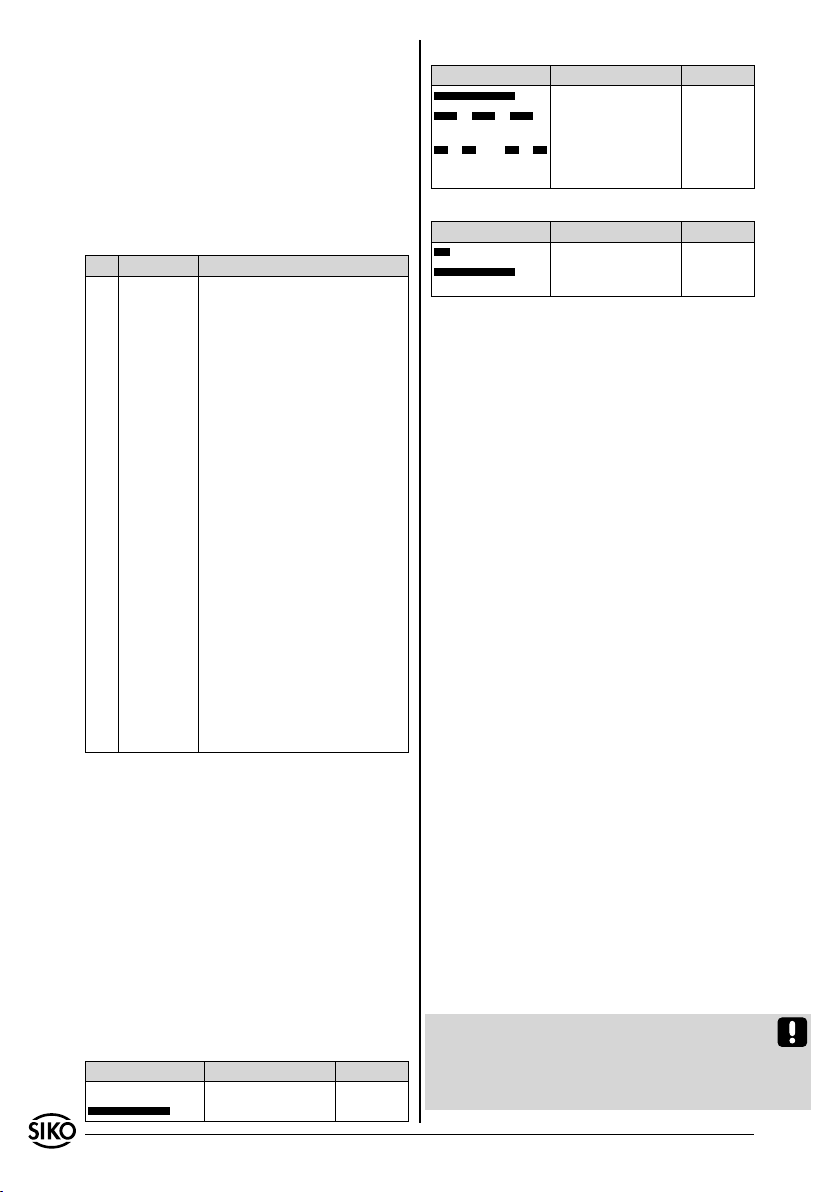
7.1 Statusanzeigen der LED's
LED "SSI Takt" (rot)
Anzeige Bedeutung Behandlung
(AUS) SSI-Takt AUS Kapitel 9
(EIN) SSI-Takt EIN Kapitel 9
4 AEA111/1 Datum 25.01.2008 Art.Nr. 84155 Änd. Stand 245/07
LED "Ein" (grün)
Anzeige Bedeutung Behandlung
(EIN) 24VDC EIN --
(EIN.....AUS.....EIN...)
(2xEIN...AUS...2xEIN...)
Abgleich aktiv Kapitel 7.2
Überwachung des Positionswertes im Modus
Millimetersprung
Kapitel 8.4
LED "Fehler" (rot)
Anzeige Bedeutung Behandlung
(EIN...AUS) Kalibrierung beendet Kapitel 7.3
(EIN) Sensor/ Bandabstand/
Kabelbruch
Kapitel 8.1
und 8.2
7.2 Sensorabgleich
Bei Austausch der Auswerteelektronik, eines Sensorkopfes oder des Magnetbandes ist ein Neuabgleich des Systems nötig. Der Grund ist, dass
jeder Sensor nach dem Abgleich einer bestimmten
Auswerteelektronik zugeordnet ist und die spezifischen Sensor- bzw Banddaten in dieser nichtflüchtig abgespeichert werden.
Die Abgleichroutine kann per RS485 oder durch
Betätigen von SW1.4 gestartet werden (siehe Kap.
6.3).
(~2 sec ON, danach wieder OFF)
Während des Abgleichs blinkt die LED "Ein" gleich-
mäßig. Der Sensorkopf muss ruckfrei und mit langsamer Geschwindigkeit (~3mm/sec) in Richtung
des Kabelabganges bewegt werden. Sobald die LED
"Ein" wieder statisch leuchtet, ist der Abgleich beendet.
Zu diesem Zeitpunkt sollte die Zählrichtung eingestellt sein (Kap. 6.2)
7.3 Kalibrierung des Messystems
Bei der AEA111/1 handelt es sich um ein absolutes
Messsystem, d.h. die Information des Positionswertes ist als Absolutwert im Maßstab verkörpert.
Nach erfolgreichem Sensorabgleich kann der Kalibrierpunkt an jeder beliebigen Stelle frei definiert
werden.
Die Kalibrierung kann wahlweise per RS485
Schnittstelle oder mit SW1.5 vorgenommen werden (~1sec. ON, danach wieder OFF).
An der aktuellen Sensorposition wird fortan der
Wert Positionswert = 0 + Kalibrierwert ausgegeben.
Mit der Kalibrierung wird der aktuelle Positionswert durch den eingestellten Kalibrierwert ersetzt
und nichtflüchtig gespeichert.
Achtung! Ab Werk ist dieser Wert auf "0" voreingestellt (WE), daher erscheint standardmäßig
der Positionswert "0". Der Kalibrierwert kann via
RS485 (Kapitel 10.1) verändert werden und wird
ebenfalls nichtflüchtig gespeichert.
Page 5
Die Kalibrierung ist nur auf ein abgeglichenes System bezogen (siehe Kapitel 7.2 Sensorabgleich).
Nach einem Austausch einer der Komponenten ist
der Abgleich zu wiederholen!
7.3.1 Kalibrierung in der Betriebsart RS485
In der Einstellung Service Standard-Protokoll
•
(siehe Kapitel 10.1):
Eingabe des Schnittstellenbefehls: "S00000"
(siehe Kap. 10.1.1)
oder
In der Einstellung SIKONETZ3-Protokoll
•
(siehe Kap. 10.2):
Eingabesequenz der Schnittstellentelegramme:
Programmiermode EIN, Kalibrierung, Programmiermode AUS (siehe Kap. 10.2)
Telegrammbeispiel:
Gerät mit Adresse 1 soll kalibriert werden.
Master sendet (hex): 81 32 63
1.
AEA111/1 antwortet (hex): 81 32 63
Kurztelegramm an/ von Adresse 1 (81h);
Programmiermode Ein (32h); Prüfbyte (63h)
Master sendet (hex): 81 48 C9
2.
AEA111/1 antwortet (hex): 81 48 C9
Kurztelegramm an/ von Adresse 1 (81hex);
Kalibrierung (48hex); Prüfbyte (C9hex)
Master sendet (hex): 81 33 62
3.
AEA111/1 antwortet (hex): 81 33 62
Kurztelegramm an/ von Adresse 1 (81hex);
Programmiermode Aus (33hex); Prüfbyte
(62hex)
oder
Setzen des SW1.5 für >1s in Stellung ON, danach
•
wieder in Stellung OFF zurücksetzen.
7.3.2 Kalibrierung in der Betriebsart SSI:
Setzen des SW1.5 für >1s in Stellung ON, danach
•
wieder in Stellung OFF zurücksetzen.
Die Quittierung des Kalibriervorgangs erfolgt durch
einmaliges kurzes Blinken der "Fehler"-LED.
8. Überwachte Funktionen der AEA111/1
Die Auswerteelektronik überwacht im eingeschalteten Zustand permanent die Signalamplitude, sowie die Verfahrgeschwindigkeit des Sensorkopfes.
8.1 Überwachung Magnetband
Sobald der Sensorkopf vom Magnetband abgehoben wird,
leuchtet die rote LED "Fehler" konstant.
•
wird anstelle des Positionswertes via RS485 der
•
Wert +99999999 ausgegeben.
AEA111/1 Datum 25.01.2008 Art.Nr. 84155 Änd. Stand 245/07 5
wird im Systemstatus-Register das Bit 0 gesetzt
•
(dynamisch).
Achtung! Die Position des Sensorkopfs muss auf
der gesamten Messlänge hinsichtlich der Ausrichtung und des Abstandes zum Magnetband kontrolliert werden.
8.2 Überwachung auf Kabelbruch
Falls die Anschlussleitung des MSA111 zur
AEA111/1 unterbrochen ist,
leuchtet die rote LED "Fehler" konstant.
•
wird anstelle des Positionswertes via RS485 der
•
Wert +99999998 ausgegeben.
wird im Systemstatus-Register das Bit 3 ge-
•
setzt.
Abhilfe: Das System muss zunächst stromlos geschaltet und die Verbindung wieder hergestellt
werden!
8.3 Überwachung des Positionswertes im Modus
"Geschwindigkeitsmessung"
Dieser Modus kann benutzt werden um anzuzeigen,
wenn der Sensorkopf schneller als ~0,3m/s bewegt
wird, da in diesem Fall eine korrekte Decodierung
der Absolutinformation nicht mehr gewährleistet
ist. Hierzu müssen SW1.5 und SW1.6 in der Position OFF stehen (WE). In diesem Modus:
wird im Systemstatus-Register das Bit 5 gesetzt,
•
wenn der Sensor schneller als ~0,3m/s verfahren
wird.
funktionieren die SSI und die RS485 Ausgabe
•
davon unbeeinflusst.
Achtung! Der Fehler setzt sich selbst zurück, sobald die Verfahrgeschwindigkeit wieder reduziert
wird.
8.4 Überwachung des Positionswertes im Modus
"Millimeter-Sprung"
Nachdem der Sensor lagerichtig und innerhalb der
Montagetoleranzen über dem Magnetband montiert und der Sensorabgleich erfolgreich durchgeführt wurde, kann die korrekte Funktion des Systems in diesem Modus verifiziert werden.
Hierzu müssen SW1.5 und SW1.6 innerhalb ~2s
gleichzeitig in die Stellung ON gesetzt werden und
dürfen danach nicht mehr geändert werden:
Die grüne LED "EIN" blinkt jetzt: 2x kurz...
•
Pause...2x kurz...
Die SSI und die RS485 Ausgabe funktionieren
•
davon unbeeinflusst.
Der Sensor kann nun über die gesamte Messlänge
bewegt werden (< 10mm/s). Sobald ein Positionssprung > 1mm erkannt wird,
leuchtet die rote LED "Fehler"
•
wird im Systemstatus Register das Bit 1 ge-
•
setzt.
Page 6
bleibt der Fehler so lange gesetzt, bis SW1.5 kurz
•
in die Stellung OFF - ON bzw. SW1.5 und SW1.6
in Stellung OFF gesetzt werden.
Achtung!
Die Position des Sensorkopfs muss an der Stelle,
•
an der der Fehler auftrat hinsichtlich der Ausrichtung und des Abstandes zum Magnetband
kontrolliert werden!
Falls die Montage nicht die Ursache des Fehlers
•
ist, kann ein Neuabgleich durchgeführt werden
(siehe Kap. 7.2 Sensorabgleich)
Sollte der Fehler danach immer noch auftreten,
•
kontaktieren Sie bitte unseren technischen
Support.
Nachdem die komplette Messlänge in beiden Verfahrrichtungen störungsfrei verifiziert wurde, kann
der Modus "Millimeter-Sprung" beendet werden,
indem SW1.5 und SW1.6 wieder in die Stellung
OFF gesetzt werden.
Achtung! Die SSI Schnittstelle wird beim Erkennen des dynamischen Betriebs oder eines Positionssprunges bewusst nicht abgeschaltet, da eine
Steuerung dies als Kabelbruch detektieren könnte
und in Störung geht. Das kurzzeitige Auftreten
von Positionssprüngen hingegen, kann durch eine
Plausibilitätsprüfung der Steuerung erkannt und
überprüft werden.
9. SSI-Schnittstelle der AEA111/1
Positionswertausgabe im SSI-Mode
Bei angeschlossenem SSI-Taktsignal leuchtet die
rote LED "SSI-Takt". Durch die Optoentkopplung
der SSI-Takt-Eingänge auch dann, wenn die +24VVersorgungsspannung noch ausgeschaltet ist.
Die integrierte SSI-Schnittstelle der AEA111/1
ermöglicht eine synchrone Ausgabe des Positionswertes, dessen Datenformat eine Breite von 24Bit
(1Bit (MSB) Vorzeichen + 23Bit Positionswert)
umfasst, die rechtsbündig ausgegeben werden.
Der Ausgabekode erfolgt Gray- oder Binär-kodiert
(siehe Kapitel 6.2). Alle nachfolgenden Bits (25,
26...) werden mit "0" ausgegeben (siehe Doku-
ment "ssi_hard_signale_asa510.pdf").
Die Datensignale entsprechen der Norm RS422.
Die Takteingänge sind optoentkoppelt und entsprechen ebenfalls der RS422. Die SSI Monoflopzeit beträgt typ. 20...25µs. Daraus ergibt sich die
minimale Taktrate von 62,5kHz.
Die maximale Taktrate beträgt 1MHz und wird,
auch im Hinblick auf die Datensicherheit, im Wesentlichen durch die Länge der Anschlussleitung
eingeschränkt. Es können folgende Richtwerte genannt werden:
Leitungslänge Max. Taktrate
2m 1MHz
10m 800kHz
100m 250kHz
200m 125kHz
Achtung! Unter folgender Bedingung wird der
Treiberausgang der SSI-Schnittstelle deaktiviert:
Der externe Konfigurationseingang wurde bei
•
eingeschalteter Versorgungsspannung auf +24VDC
gelegt (siehe Kap. 12).
Applikationsbeispiel Positionsanzeige
"SSI-Mode"
Netzteil:
24VDC/
500mA
+24VDC/GND
AEA111/1
Takt+/Takt-/
Daten+/ Daten-
z.B. MA10/4
SSI
Abb. 2: Blockschaltbild SSI
Konfiguration der SIKO-Messanzeige MA10/4 SSI:
Gebertyp "linear", Geberbits "24", Faktor "1.0"
(1/100mm Anzeige), Ausgabekode "Gray"
10. RS485-Schnittstelle der AEA111/1
Positionswertausgabe und Parametrierung im
RS485-Mode
Die AEA111/1 kann über die integrierte RS485
Schnittstelle an die jeweiligen Bedürfnisse angepasst werden. Hierfür besteht die Möglichkeit,
einige spezifische Parameter zu programmieren,
die dann nichtflüchtig gespeichert werden und jederzeit geändert werden können.
Achtung! In der Betriebsart RS485 wird SW1.3
während des Einschaltens der Betriebsspannung
nicht ausgewertet.
10.1 Protokollbeschreibung Service-Standard-
Protokoll (siehe Kap. 6.1)
Das Service-Standard-Protokoll ermöglicht die Parametrierung, Positionswertausgabe und Diagnose
der AEA111/1. Die Datensignale entsprechen der
Norm RS485. Da das Service-Standard-Protokoll
nicht busfähig ist, dürfen keine weiteren Geräte
an der RS485 angeschlossen sein.
Überprüfen Sie vor dem Einschalten der Versorgungsspannung die Stellung von SW1.1 und
SW1.2:
SW1.1 = OFF (RS485-Mode)
In der Betriebsart "RS485-Mode" (SW1.1=OFF)
ist das Service-Standard-Protokoll nur in Stellung
SW1.2=OFF verfügbar.
SW1.2 = OFF (Service Standard-Protokoll)
6 AEA111/1 Datum 25.01.2008 Art.Nr. 84155 Änd. Stand 245/07
Page 7
Stellen Sie über einen Pegelwandler (z.B. Fa. Spectra Typ I-7520) eine Verbindung zwischen der seriellen RS232 Schnittstelle Ihres PCs und der RS485Schnittstelle der Auswerteelektronik her.
Nachdem die Versorgungsspannung der AEA111/1
eingeschaltet wurde, können Sie sofort mit der
Programmierung beginnen, indem Sie ein geeignetes Terminalprogramm (z.B. "sikoterm.exe")
starten und ihre Befehle gemäß der Tabelle "Befehlsliste-Servicebetrieb" manuell eingeben (siehe
Kap. 9.1.1). Berücksichtigen Sie dabei die vorgegebenen Schnittstellenparameter.
Applikationsbeispiel PC/ Terminal
Netzteil:
24VDC/
500mA
+24V/GND
AEA111/1
"RS485-Mode"
DÜA/DÜB/GND
MSA111
Pegelwandler
RS485<->RS232
RXD/TXD/GND
PC
RS232
Abb. 3: Blockschaltbild RS485
10.1.1 Befehlsliste Service Standard-Protokoll
Prinzipiell funktioniert die Anwendung so, dass
der PC (oder ein Terminal) einen ASCII-Befehl
(Buchstabe) ggf. mit zusätzlichen Zahlenparametern absendet. Die AEA111/1 sendet daraufhin die
entsprechende Antwort (siehe folgende Tabelle):
Parameter: 19200 Baud, keine Parität, 8 Bit, 1
Stoppbit, ohne Handshake
Ausgabe: ASCII (falls nicht anders angege-
ben)
Wertebereiche: 2/3 Byte: 0...65535 / 0... ±2
23
Zur Eingabe: Es werden große und kleine Buch-
staben akzeptiert.
Zur Ausgabe: Mit Ausnahme des Befehls "W"
werden alle Antworttelegramme
mit einem CR (=hex13) vervollständigt.
Befehl Länge Antwort Bemerkungen
A0 2/10 xxxxxxxx> Hardware Kennung
A1 2/7 xxxxx> Firmware Version
A2 2/10 xxxxxxxx> Reserviert
A3 2/7 xxxxx> Reserviert
B 1/10 +xxxxxxx> Positionswert ohne Korrekturwerte
Ey 2/10 +xxxxxxx> Parameter ausgeben (in 1µm auf-
gelöst)
y = Adresse (0...4)
x = dezimaler Wert
y = 0: Positionswert
y = 2: Nullpunktwert
y = 3: Kalibrierwert
y = 4: Bereichsgrenze
Befehl Länge Antwort Bemerkungen
Fy+xxxxxxx 10/2 > 3-Byte-Wert eingeben (in 1µm
H 1/4 für interne Zwecke: Parameterda-
K 1/- Software Reset (Gerät wird neu
M 1/4 xx> SIKONETZ3 Adresse ausgeben (WE
Nxx 3/2 > SIKONETZ3 Adresse zweistellig
Q 2/x Für interne Zwecke: (Parameter-
Ry_xxxxxxxx 11/2 > Konfigurationsregister in binärer
S00000 6/2 > Positionswert auf Kalibrierwert
S11100 6/2 > Auslieferungszustand wiederher-
S00100 6/2 > Sensorabgleich starten
S01001 6/2 > Absolutdekodierung / SSI deakti-
S01002 6/2 > Absolutdekodierung / SSI aktivie-
S01003 6/2 > Positionswert wird im Modus "Mil-
S01004 6/2 > Positionswert wird im Modus "Ge-
T0 2/2 > Zählrichtung POSITIV (WE)
T1 2/2 > Zählrichtung NEGATIV
U 1/x Für interne Zwecke: (Parameter-
V 1/x Für interne Zwecke: (Parameter-
W 1/4 xxxx Absoluter Positionswert im Binär-
X 1/6 0xyy> Systemstatus Register ausgeben
aufgelöst)
y = Adresse (2...4)
y = 2: Nullpunktwert (WE = 0)
y = 3: Kalibrierwert (WE = 0)
y = 4: Bereichsgrenze (WE = 0)
Wenn "0" eingestellt, wird Positionswert -96..4000mm ausgegeben
x = dezimaler Wert (±0...9999999)
ten
gestartet)
= 01)
eingeben
xx = dezimaler Wert (01...31)
daten)
Schreibweise eingeben
y = 0: Register 0
y = 1: Register 1
_ = Trennzeichen
x = 0 oder 1
xxxxxxxx = Bit7,6,5...0: Registerinhalt
setzen
stellen (default-setting)
SIKONETZ3 Adresse: 01
Positionswert Filter: EIN
Zählrichtung: POSITIV
SSI Kode: Gray
RS485 Startmessage: no
Fehler-Status löschen
Kalibrierdaten (Nullpunkt-/ Kalilbrierwert): 0
vieren (flüchtig)
(entspricht: Konfigurationseingang
= 24V)
ren (WE)
(entspricht: Konfigurationseingang
= 0V)
limeter Sprung" überwacht (flüchtig)
schwindigkeitsmessung" überwacht
(WE)
daten)
daten)
Code und ohne CR
(hex)
AEA111/1 Datum 25.01.2008 Art.Nr. 84155 Änd. Stand 245/07 7
Page 8
Befehl Länge Antwort Bemerkungen
Y0 2/6 0xyy> Konfigurations Register-0 ausge-
Y1 2/6 0xyy> Konfigurations Register-1 ausge-
Z 1/10 +xxxxxxx> Absoluten Positionswert ausgeben
ben (hex)
ben (hex)
10.2 Protokollbeschreibung SIKONETZ3
Das SIKONETZ3-Protokoll ermöglicht die Parametrierung und Positionswertausgabe der AEA111/1.
Die Datensignale entsprechen der Norm RS485. Da
jedes Telegramm eine Adresse beinhaltet, können
bis zu 31 Geräte über einen Bus angesprochen werden. Im Auslieferungszustand ist diese Adresse bei
jedem Gerät auf den Wert "01" eingestellt. Bevor
das Gerät am Bus betrieben wird, sollten deshalb
zunächst via Service Standard-Protokoll (siehe Kapitel 10.1) sämtliche Parameter (Zählrichtung, Kalibrierwert...), insbesondere aber die Geräteadresse
(01...31) umprogrammiert werden. Nach dieser
Grundparametrierung kann schließlich auf das SIKONETZ3-Protokoll umgeschaltet, und somit in den
Busbetrieb gewechselt werden SW1.2=ON.
Das SIKONETZ3-Protokoll ist als Master-Slave-System aufgebaut, in dem die AEA111/1 immer als
Slave eingeordnet ist. Es existieren 2 Telegrammlängen:
3 Byte:
Adress-
Befehl Prüf-
Byte
Byte
6 Byte:
Adress-
Befehl Daten-
Byte
Byte
Low
Daten-
Byte
Middle
Daten-
Byte
High
Prüf-
Byte
Das Adressbyte setzt sich wie folgt zusammen:
1 0 A0 A1 A2 A3 A4 0 RR L 1
Start LSB MSB Stopp
Das Prüfbyte wird als EXOR-Verknüpfung der restlichen 2 bzw. 5 Bytes des Telegramms erzeugt.
A0 ... A4: Binärkodierte Adresse 1 ... 31;
Adresse 0 definiert für Master
RR: Rundruf-Bit = 1 Befehl gilt für alle
Geräte, Geräte antworten nicht
L: Längen-Bit: 1 = Kurztelegramm (3 Byte)
0 = Langtelegramm (6 Byte)
Parameter: 19200 Baud, keine Parität, 8 Bit,
1 Startbit, 1 Stoppbit
Spalte Erläuterung
Hex Hexadezimalwert des Befehls
TX Telegrammlänge vom Master an
AEA111/1
RX Telegrammlänge von AEA111/1 an
Master
S Übergebener Parameter wird nicht-
flüchtig im Gerät gespeichert
P Für diesen Befehl ist es notwendig,
den Programmiermode einzuschalten
(Befehl 0x32; 0x33)
R Dieser Befehl ist rundruffähig
Hex TX RX S P R Funktion
0x16 3 6 - - - Positionswert auslesen
0x18 3 6 - - - Kalibrierwert auslesen
0x1b 3 6 - - - Gerätekennung auslesen
0x1d 3 6 - - - Zählrichtung auslesen
0x28 6 6 S P - Kalibrierwert programmieren
0x2d 6 6 S P - Zählrichtung programmieren
0x32 3 3 - - - Programmiermode "Ein"
0x33 3 3 - - - Programmiermode "Aus"
0x3a 3 6 - - - Systemstatus ausgeben
0x3b 3 3 - - - Systemstatus löschen
0x48 3 3 S P - Positionswert wird auf Kalibrier-
0x4F 3 3 - - R Postionswert einfrieren. Positions-
D-Byte 1: Kennung 26 (Dez.);
D-Byte 2: Softwareversion
D-Byte 3: Hardwareversion
Wert = 0: "auf" (+)
Wert = 1: "ab" (-)
Wert auf den der Positionswert
gesetzt wird, wenn das Gerät kalibriert wird (Befehl 0x48)
Wert = 0: "auf" (+)
Wert = 1: "ab" (-)
Default
Systemstatus Bytes 2 und 3 werden gelöscht
wert gesetzt.
wert wird eingefroren. Zustand wird
durch Auslesen des Positionswertes
zurückgesetzt. Dient zum synchronisierten Auslesen mehrerer Geräte.
Fehlermeldungen
Der Slave (AEA111/1) erkennt Übertragungs- bzw.
Eingabefehler und sendet folgende Fehlermeldungen:
Hex TX RX S P R Funktion
0x82 - 3 - - - Datenübertragungsfehler Prüfsumme
0x84 - 3 - - - Unzulässiger oder unbekannter
0x88 - 3 - - - Unzulässiger Wert (Parameter Pro-
Befehl
grammierung)
8 AEA111/1 Datum 25.01.2008 Art.Nr. 84155 Änd. Stand 245/07
Page 9
Synchronisation:
Eine Byte-/Telegrammsynchronisation erfolgt über
"Timeout": Der Abstand der einzelnen Bytes eines
Telegramms dürfen einen Wert von 10ms nicht
übersteigen. Falls ein angesprochenes Gerät nicht
antwortet, so darf der Master frühestens nach
30ms erneut ein Telegramm senden.
Telegrammbeispiel:
Positionswert des Geräts mit Adresse 7 soll ausgegeben werden.
Master sendet (hex): 87 16 91
Kurztelegramm an Adresse 7 (87hex); Positions-
wert auslesen (16hex); Prüfbyte (91hex)
AEA111/1 antwortet (hex): 07 16 03 02 00 10
Langtelegramm von Adresse 7 (07hex); Positions-
wert auslesen (16hex); Wert 203h = 515 dez (03 02
00hex); Prüfbyte (10hex).
11. Übersicht Bit Zuordnung der einzelnen Register
11.1 8 Bit Systemstatus Register
Bit Default Bemerkungen
0 0 FEHLER-Bit: unzulässiger Sensor-
Bandabstand bzw. Bandunterbrechung
1 0 FEHLER-Bit: Positionssprung aufge-
treten
2 0 Konfigurationseingangs-Bit: Wird
gesetzt, solange am Konfigurationseingang +24V angelegt sind.
3 0 FEHLER-Bit: Sensoranschlusslei-
tung ist unterbrochen
4 0 ABGLEICHSSTATUS: Wird gesetzt
während Sensorabgleich läuft
5 0 FEHLER-Bit: Geschwindigkeitsmes-
sung
6...7 - -
Die Fehlerbits 0, 1 und 3 bleiben gesetzt bis entsprechende Quittierung erfolgte.
11.2 8Bit Konfigurations Register-0
Bit Default Bemerkungen
0 0 Wenn gesetzt, wird nach Einschal-
ten der +24V eine Kennung über
die RS485 (sofern aktiv) gesendet
-> Startmessage
1 0 Zählrichtung:
0 = POSITIV;
1 = NEGATIV
2 1 SSI-Kode:
0 = Binär
1 = Gray
AEA111/1 Datum 25.01.2008 Art.Nr. 84155 Änd. Stand 245/07 9
Bit Default Bemerkungen
3 0 (für interne Zwecke: HALL Deco-
4 0 Positionwertüberwachung:
5 1 Positionswert Filter:
6 1 Kabelbrucherkennung:
7 0 not used
11.3 8Bit Konfigurations Register-1
Bit Default Bemerkungen
0...7 0 (für interne Zwecke)
dierung)
0 = Geschwindigkeitsmessung
1 = Millimeter-Sprung
0 = AUS
1 = EIN
0 = AUS
1 = EIN
12. Konfigurationseingang der AEA111/1
Sobald der Konfigurationseingang auf +24VDC gelegt wird, wird nach einem kurzen Entprelldelay
(~1sec.) die SSI-Schnittstelle und die Elektronik
zur Erfassung der Absolutinformation aus dem
Sensorkopf deaktiviert. Diese Funktion kann verwendet werden, um das unvermeidliche Signalrauschen auf der Sensorleitung und damit verbunden,
den analogen Ausgängen sin / cos zu minimieren.
Sofern der Konfigurationseingang bereits beim
Einschalten auf +24VDC gelegt ist, wird dieser Zustand nicht bewertet, da damit die Absolutposition nicht ermittelt werden könnte. Erst nach einer
StartUp Verzögerung von ~0,5s werden Änderungen an den SW1-Schaltern und auch am Konfigurationseingang ausgewertet.
13. Fehlerbehandlung
Typische Fehler, die bei Anbau und Betrieb auftreten können:
Die AEA111/1 ist nicht oder nicht korrekt ange-
•
schlossen (Pinbelegung siehe Kap.5).
Die Abstandstoleranz zwischen Sensor/ Band
•
wurde nicht eingehalten (über die gesamte
Messstrecke!) oder der Sensor streift auf dem
Magnetband.
Kabelunterbrechung/ Abtrennung durch scharfe
•
Kanten/ Quetschung.
Der Sensor ist mit der aktiven Seite vom Band
•
abgewandt montiert.
Falsche Messwerte infolge EMV-Störungen (siehe
•
Kap. 5)
Die eingestellte Betriebsart entspricht nicht der
•
angeschlossenen Hardware.
Page 10
10 AEA111/1 Datum 25.01.2008 Art.Nr. 84155 Änd. Stand 245/07
Page 11
User Information
AEA111/1
Translation module
ENGLISH
1. Warranty information
In order to carry out installation correctly, we
•
strongly recommend this document is read very
carefully. This will ensure your own safety and
the operating reliability of the device.
Your device has been quality controlled, tested
•
and is ready for use. Please observe all warnings
and information which are marked either directly
on the device or specified in this document.
Warranty can only be claimed for components
•
supplied by SIKO GmbH. If the system is used
together with other products, there is no warranty
for the complete system.
Repairs should be carried out only at our works.
•
If any information is missing or unclear, please
contact the SIKO sales staff.
2. Identification
Please check the particular type of unit and type
number from the identification plate. Type number
and the corresponding version are indicated in the
delivery documentation.
e.g. AEA111/1-0023
version number
type of unit
3. Kurzbeschreibung
The AEA111/1 is a translation module, which establishes a high-resolution magnetic absolute value
measuring system when used in combination with
the absolute sensor MSA111 and the magnetic
strip MBA111.
The following outputs are available: an RS-485-interface (for device configuration or realization of
the SIKONETZ3 protocol (SN3) respectively), the
SSI interface and a 1VSS analog output (sin/cos).
4. Mounting instructions
For mounting, the degree of protection specified
must be observed. If necessary, protect the unit
against environmental influences such as sprayed
water, dust, knocks, extreme temperatures.
4.1 Mounting device
The AEA111/1 has been designed for mounting
on tophat rails (35x7,5) accord. to DIN 50022.
For mounting, snap the retainer onto the rail and
ensure that the locking is at the device's bottom
side. For dismounting press locking down.
Fig. 1: Installation
5. Electrical connection
Switch power off before any plug is inserted
•
or removed!!
Wiring must only be carried out with power off.
•
Provide standed wires with ferrules.
•
Check all lines and connections before switching
•
on the equipment.
To ensure flawless functioning of the device,
•
expert connection to potential equalization is
indispensable. To ensure this, a female connector
for receiving a 6,3mm tab is integrated in the
front plate of the AEA111/1. The connection
should be as short as possible.
Interference and distortion
All connections are protected against the effects
of interference. The location should be selected
to ensure that no capacitive or inductive interferences can affect the encoder or the connection lines! Suitable wiring layout and choice
AEA111/1 Datum 25.01.2008 Art.Nr. 84155 Änd. Stand 245/07 11
Page 12
6
9
1
6
9
1
6
5
1
5
1
2
3
1
5
9
1
2
6
3
1
9
5
1
2
1
3
6
8
1
of cable can minimise the effects of interference
(eg. interference caused by SMPS, motors, cyclic
controls and contactors).
Necessary measures:
Only screened cable should be used. Screen should
•
be connected to earth at both ends. Wire cross
section is to be 0,25mm2.
Wiring to screen and to ground (GND) must be
•
via a good earth point having a large surface area
for minimum impedance.
The unit should be positioned well away from
•
cables with interference; if necessary a protective
screen or metal housing must be provided. The
running of wiring parallel to the mains supply
should be avoided.
Contactor coils must be linked with spark sup-
•
pression.
To enhance interference resistance of the
•
AEA111/1 the connecion line for power supply
and output signals should have a ferrite sleeve
mounted at a very short distance from the D-SUB
connection. Since the outer diameter depends on
the type of the connection line, a suitable sleeve
should be selected.
Power supply: 24VDC±20%
Power consumption: < 8 Watt
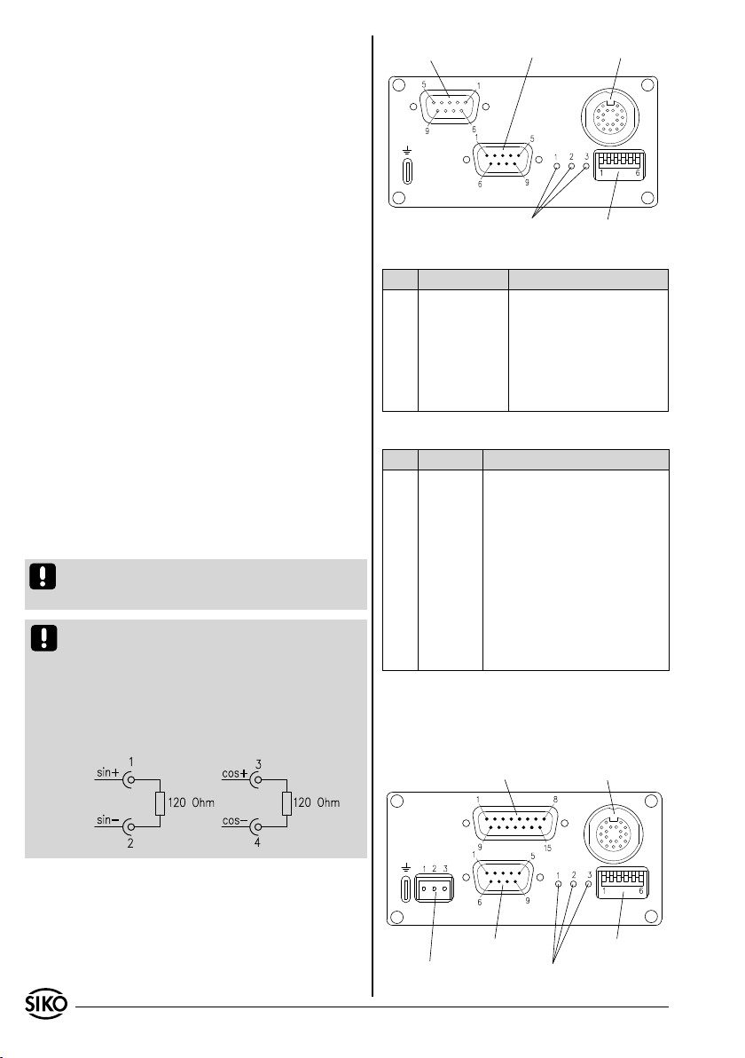
5.1 Pin connection
Attention! Fixing of the D-Sub plug to the socket
is to be made by using the screws in the plug. this
will guarantee a neat and effective connection.
Attention! If the analog signals are not further
processed it is recommended to terminate each
the sin+ and sin- as well as the cos+ and cos- outputs with a 120 Ohm resistor.
In case the analog signals are further processed,
take care that a terminator is included in the receiving electronics unit.
X1/Output
X2/Interface Sensor
Status LED
SW1/Parameter
Pin Connection Output X1
PIN Signal Description
1 sin+ positive sinus output
2 sin- negative sinus output
3 cos+ positive cosinus output
4 cos- negativer cosinus output
5 Analog_GND Ground analog signal
6-9 - n.c.
Interface X2
PIN Signal Description
1 +24VDC voltage supply of translation
module +24VDC ±20%
2 SSI cycle+ SSI cycle input, opto-decoupled
3 RS485 DÜA Serial service interface
4 Ext_Config external configuration input
5 GND Ground translation module
6 SSI Daten+ SSI data output
7 SSI cycle- SSI cycle input, opto-decoupled
8 RS485 DÜB Serial service interface
9 SSI data- SSI data output
5.1.2 Pin connection EB
The output signals are carried via a 9-pin and/or
15-pin D-SUB connector and the supply voltage is
carried via a 3-pin connector.
X1/Output
Sensor
5.1.1 Pin Connection EA
The output signals and the supply voltage are each
carried via a 9-pin D-SUB connector.
12 AEA111/1 Datum 25.01.2008 Art.Nr. 84155 Änd. Stand 245/07
X3/Interface
X4/Operation voltage
Status LED
SW1/Parameter
Page 13
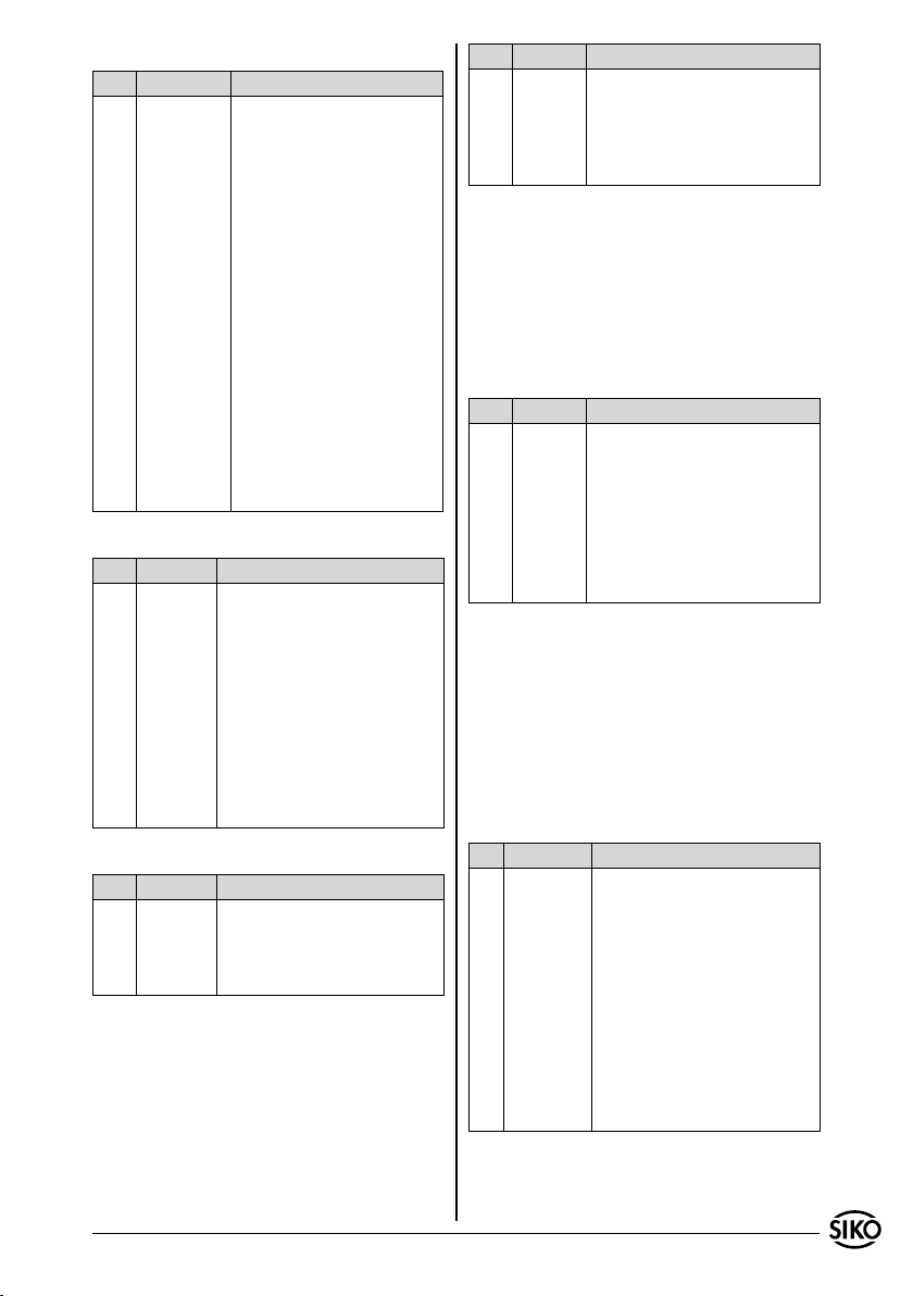
Pin Connection Output X1
PIN Signal Description
1 GND Ground translation module
2 Ext_Config external configuration input
3 sin- negative sinus output
4 cos- negativer cosinus output
5 Analog_GND Ground analog signal
6 SSI cycle+ SSI cycle input, opto-decou-
pled
7 SSI cycle- SSI cycle input, opto-decou-
pled
8 sin+ positive sinus output
9 cos+ positive cosinus output
10 Digital_GND Ground digital signal
11 Digital_GND Ground digital signal
12 Analog_GND Ground analog signal
13 Analog_GND Ground analog signal
14 SSI data- SSI data output
15 SSI data+ SSI data output
Interface X3
PIN Signal Description
1 - 2 SSI cycle+ SSI cycle input, opto-decoupled
3 RS485 DÜA Serial service interface
4 Ext_Config external configuration input
(see chapter 9, 12)
5 GND Ground translation module
6 SSI Daten+ SSI data output
7 SSI cycle- SSI cycle input, opto-decoupled
8 RS485 DÜB Serial service interface
9 SSI data- SSI data output
X4 operating voltage
PIN Signal Description
1 +24VDC voltage supply of translation
module +24VDC ±20%
2 GND Ground translation module
3 Ext_Config external configuration input
6. Parameter setup with SW1
Since the required configuration is loaded only during the start of the device, it must be set up by
means of the appropriate DIP switches (SW1 see
chapter 5.1) prior to switching on the operation
voltage.
6.1 Operating mode ("RS485 mode")
(SW1.1 = OFF; Output of position value and parameterization via RS485)
AEA111/1 Datum 25.01.2008 Art.Nr. 84155 Änd. Stand 245/07 13
DIP Position Description
1 OFF RS485 operating mode
2 OFFONRS485 Service standard protocol
3 -- No function in RS485 mode
6.2 SSI operating mode ("SSI mode")
(SW1.1 = ON; output of position value via SSI)
The cycle inputs of the SSI interface have been realised opto-decoupled and have a 150 Ohm series
resistance. The red "SSI cycle" lightemmitting diode is lighted as soon as a cycle signal is applied,
even if the 24 V supply of the translation module
has not been switched on yet. The SSI data outputs correspond to the RS422 interface.
DIP Position Description
1 ON SSI mode
2 OFFONPosition value is output in Gray
3 OFF POSITIVE counting direction
The SSI operating mode enables the simultaneous
use of the RS485 interface in the Service Standard
Protocol.
6.3 Mode-independent DIP switches
The following DIP switches are continuously polled
while the system is being supplied from the 24V
mains. After actuating a switch there is a time
delay of approx. 2s. If no switch position is changed during this time, the setting is taken over and
processed.
DIP Position Description
4 ON
5 ON
6 ON
(default)
RS485 SIKONETZ3 protocol
code (default)
Position value is output in binary
code
(default)
NEGATIVE counting direction
Actuation for ~2s starts
the alignment of MSA111 AEA111
OFF
(default)
Actuation for ~2s starts system
calibration: The current position value is set to the set calibration value (default: 0).
OFF
(default)
Actuation for ~2s resets exis-
ting error messages.
OFF
(default)
Page 14
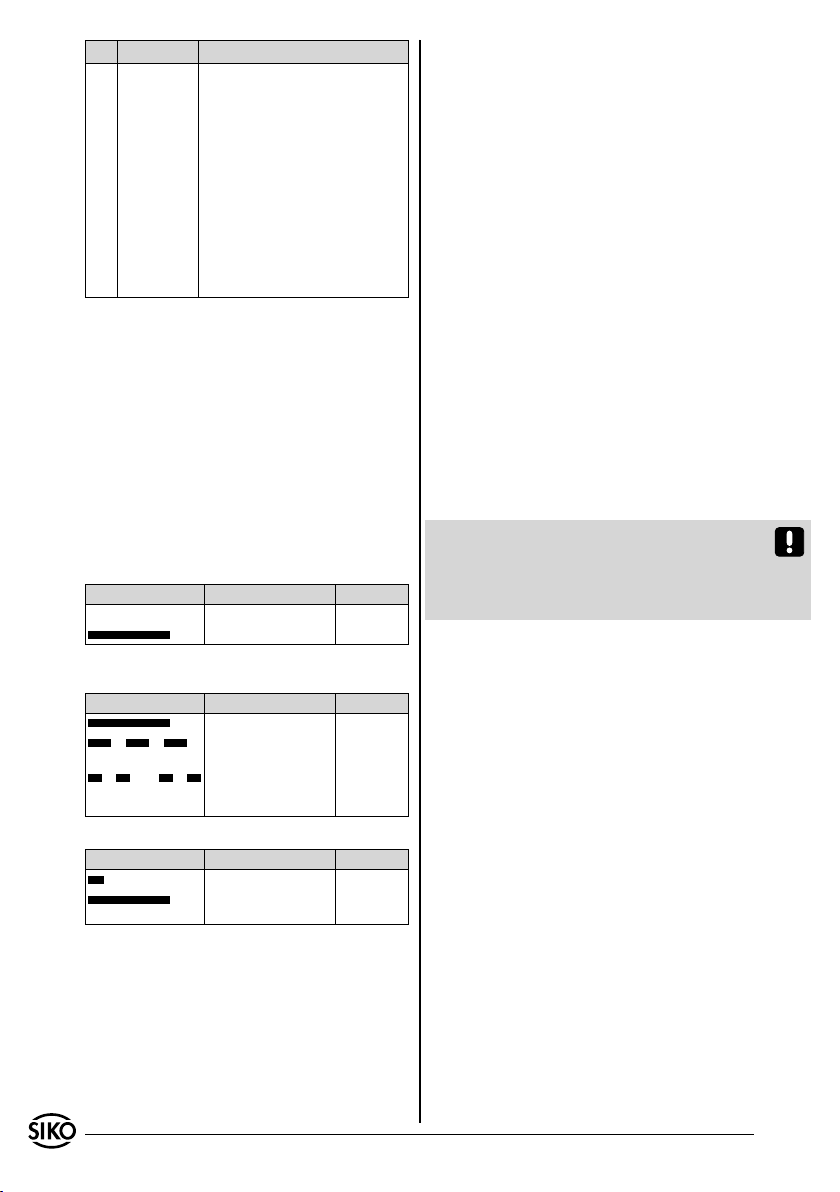
DIP Position Description
5+6 ON
Actuation of both switches
within ~2s activates the more
precise position value monitoring "millimetre jump" in the
AEA111.
OFF
(default) After simultaneous resetting of the two switches the
AEA resumes monitoring of the
position values in the "speed
measurement" mode (for the
description see the sensor monitoring section).
7. Commissioning
After proper installation, wiring and parameterization, the translation module can be commissioned
by turning on the 24V supply. With each poweron procedure, the device goes through a so-called
"startup routine". In this phase, the DIP switches
are read and the translation module is determined
depending on the parameterization (chapter 6).
Constant lighting of the green "Power" LED indicates that the device is ready for operation.
7.1 Status lights of the LEDs
"SSI cycle" LED (red)
Display Meaning Action
(OFF) SSI cycle OFF chapter 9
(ON) SSI cycle ON Kapitel 9
"Power" LED (green)
Display Meaning Action
(ON) 24VDC ON --
(ON......OFF.......ON...)
(2xON.....OFF...2xON...)
"ERROR" LED (red)
Display Meaning Action
(ON...OFF) calibration completed chapter 6.3
7.2 Sensor alignement
When replacing a translation module, sensor head
or magnetic strip the system must be re-aligned.
The reason is that each sensor is allocated to a
specific translation module following alignment
since the specific sensor data is stored non-volatilely in the respective translation module.
calibration active chapter 6.2
Position value monitoring in the millimetre
jump mode
(ON) sensor/ strip gap
cable break
chapter 8.4
chapter 8
The alignment routine can be started via RS485 or
by actuating SW1.4 (see chapter 6.3).
(~2 sec ON, then OFF again)
During alignment, the "POWER" LED blinks evenly.
Smoothly move the sensor head towards the cable outlet at low speed (~3mm/sec). Alignment
is completed as soon as the "POWER" LED glows
statically again (chapter 6.2).
7.3 Calibration of the measuring system
The AEA111/1 is an absolute measuring system,
i.e. the information of the position value is represented on the scale as an absolute value.
Following successful sensor alignment, the calibration point can be freely defined at any desired
position.
Calibration can be performed either via RS485 interface or SW1.5 (~1sec. ON, then OFF again).
Afterwards, the value position value = 0 + calibration value will be output at the current position .
With calibration the current position value is
replaced by the set calibration value and stored
non-volatilely.
Attention! This value is factory-set to "0"; therefore, the position value "0" is displayed as the default value. the calibration value can be changed
via RS485 (chapter 10.1) and is also stored in the
non-volatile memory.
Calibration relates to one aligned system only
(see chapter 7.2 sensor alignment). The procedure
must be repeated after replacing one of the existing components!
7.3.1 Calibration in the RS485 mode
In the Service Standard-Protokoll setting (see
•
chapter 10.1):
Enter the "S00000" interface command (see
chapter. 10.1.1)
or
In the SIKONETZ3 Protocol
•
(see chapter 10.2):
Entry sequence of interface commands: p r ogramming mode ON, calibration, programming
mode AUS (see chapter 10.2)
Telegram example:
To calibrate device with address 1.
Master sends (hex): 81 32 63
1.
AEA111/1 replies (hex): 81 32 63
Short telegram to/ from address 1 (81h);
Programming mode ON (32h); sense byte
(63h)
14 AEA111/1 Datum 25.01.2008 Art.Nr. 84155 Änd. Stand 245/07
Page 15
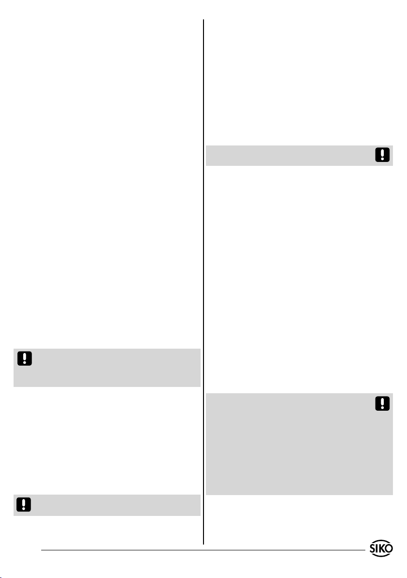
Master sends (hex): 81 48 C9
2.
AEA111/1 replies (hex): 81 48 C9
Short telegram to/ from address 1 (81h);
Calibration (48h); sense byte (C9h)
Master sends (hex): 81 33 62
3.
AEA111/1 replies (hex): 81 33 62
Short telegram to/ from address 1 (81h);
Programming mode OFF (33h); sense byte
(62h)
or
Set SW1.5 in ON position for >1s, then reset to
•
OFF position.
7.3.2 Calibration in the SSI mode:
Set SW1.5 in ON position for >1s, then reset to
•
OFF position.
The calibration process is acknowledged by one
short blinking of the "ERROR" LED.
8. Monitored AEA111/1 functions
In the turned-on state the translation module permanently monitors the signal amplitude as well as
the travel speed of the sensor head.
8.1 Magnetic strip monitoring
As soon as the sensor head is lifted off the magnetic strip,
the red "ERROR" LED glows permanently.
•
the SSI interface is deactivated (data outputs are
•
set to static high/ low).
via RS485 the value +99999999 is output instead
•
of the position value.
bit 0 is set in the system status register.
•
Attention! The position of the sensor head must
be monitored with regard to orientation and distance from the magnetic strip over the whole
measuring distance.
8.2 Monitoring for cable break
If the connection line between the MSA111 and
AEA111/1 is broken,
the red "ERROR" LED glows permanently.
•
the SSI interface is de-activated (data outputs
•
are set to static high/ low).
via RS485 the value +99999999 is output instead
•
of the position value.
bit 3 is set in the system status register.
•
Remedy: First switch the system currentless and
then re-establish the connection!
8.3 Monitoring of the position value in the "Speed
measurement" mode
This mode can be used to indicate if the sensor
head is moved faster than ~0.3m/s since correct
decoding of absolute information is no longer guaranteed in this case. SW1.5 and SW1.6 must be at
the OFF position (default) for this purpose.
In this mode:
bit 5 is set in the system status register if the
•
sensor is moved faster than ~0.3m/s.
the operation of SSI and RS485 output is not
•
influenced.
Attention! The error will be reset independently
as soon as the travel speed is reduced again.
8.4 Position value monitoring in the "Millimetre
jump" mode
After correct positioning of the sensor within the
mounting tolerances above the magnetic strip and
successful sensor alignment, the correct functioning of the system can be verified in this mode.
Forthis purpose, SW1.5 and SW1.6 must simultaneously be set to the ON position within ~2s and
must not be changed afterwards:
now, the green LED blinks: 2x short...pause...2x
•
short...
the operation of SSI and RS485 output is not
•
influenced.
The sensor can now be moved over the overall
measuring length (< 10mm/s). As soon as a position jump > 1mm is detected,
the red "ERROR" LED glows
•
bit 1 is set in the system status register.
•
the error remains set until SW1.5 is set shortly
•
to the OFF - ON position or SW1.5 and SW1.6 are
set to the OFF position.
Attention!
At the position where the error occurred the
•
position of the sensor head must be checked
with regard to alignment and distance from the
magnetic strip!
If assembly is not the cause of the error, the
•
device can be re-aligned (see chapter 7.2, sensor
alignment)
If, however, the error persists, please contact our
•
technical support.
After faultless verification of the complete measuring distance in both travelling directions the
"millimetre jump" mode can be exited by resetting
SW1.5 and SW1.6 to the OFF position.
AEA111/1 Datum 25.01.2008 Art.Nr. 84155 Änd. Stand 245/07 15
Page 16
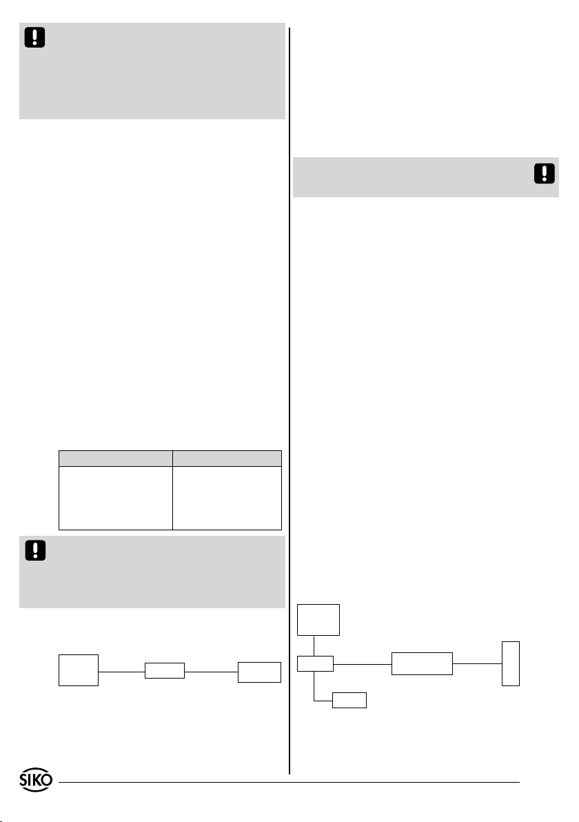
Attention! When detecting dynamic operation
or position jump the SSI interface is deliberately
not switched off since this would possibly cause a control unit to detect cable break and enter
the error state. However, the control unit can recognize and check transitory position jumps by a
marginal check.
9. SSI Interface of the AEA111/1
Output of the position value in the SSI mode
With the SSI cycle signal connected the red "SSI
cycle" LED glows. Due to opto-decoupling it glows
even if +24 supply is still switched off.
The integrated SSI interface of the AEA111/1
enables the synchronous output of the position
value, whose data format includes a 24bit width
(1bit (MSB) sign + 23bit position value), output
right aligned. the output code is Gray or binary
(see chapter 6.2). All subsequent bits (25, 26...)
are output "0" (see document "ssi_hard_signale_asa510.pdf").
The data signals comply with the RS422 standard.
the cycle inputs are opto-decoupled and comply with RS422 as well. The SSI monoflop time is
typically 20...25µs, resulting in a minimum cycle
rate of 62,5kHz.
The maximum cycle rate 1MHz and is basically limited by the length of the connection cable, also
with regard to data safety. the following standard
values apply:
cable length Max. cycle rate
2m 1MHz
10m 800kHz
100m 250kHz
200m 125kHz
Attention! The driver output of the SSI interface
is deactivated on the following condition:
The external configuration input was applied to
•
24VDC while the supply was switched on (see
chapter 12).
Applications example: Position display
"SSI-Mode"
power pack:
24VDC/
500mA
+24VDC/GND
Fig. 2: SSI block diagramm
Configuration of the SIKO magnetic display MA10/4
SSI: encoder type "linear", encoder bits "24", factor
"1.0" (1/100mm display), output code "Gray"
AEA111/1
cycle+/cycle-/
data+/ data-
eg. MA10/4
SSI
10. RS485 interface of the AEA111/1
Output of position value and parameterization
in the RS485 mode
The AEA111/1 can be customised to meet individual requirement via the integrated RS485 interface. For this purpose, some specific parameters
can be programmed, which are stored in the nonvolatile-memory and can be changed at will.
Attention! In the RS485 mode the SW1.3 switch
is not interpreted while the operating voltage is
being turned on.
10.1 Protocol description of the Service Standard
protocol
The Service Standard protocol enables parameterization, output of position values and diagnosis of
the AEA111/1. The data signals comply with the
RS485 standard. Since the Service Standard protocol is not bus-compatible, no other devices must
be connected to the RS485 interface.
Before turning on the voltage supply, check the
positions of SW1.1 and SW1.2:
DIP-Schalter 1 = OFF (RS485 mode)
DIP-Schalter 2 = OFF (Service Standard protocol)
Connect the serial interface of your PC and the
RS485 interface of the translation module by
means of a level transducer (eg. Spectra company
type I-7520).
After turning on the power supply of the AEA111/1
you may immediately start programming by starting a suitable terninal program (eg. "sikoterm.
exe") and manually entering your commands according to the "List of commands - Service mode"
table (see chapter 10.1.1). consider the interface
parameters specified.
Applcation example PC/ Terminal
power pack:
24VDC/
500mA
+24V/GND
AEA111/1
"RS485 mode"
DÜA/DÜB/GND
MSA111
level converter
RS485<->RS232
Fig. 3: Block diagram RS485
RXD/TXD/GND
PC
RS232
16 AEA111/1 Datum 25.01.2008 Art.Nr. 84155 Änd. Stand 245/07
Page 17
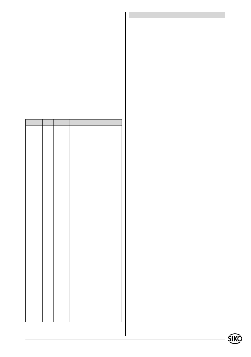
10.1.1 List of commands Service Standard
protocol
The basic principle of the application is that the
PC (or a terminal) sends an ASCII command (character), possibly with additional numeric parameters. In turn, the AEA111/1 sends an appropriate
response (see following table):
Parameter: 19200 baud, no parity, 8 bit, 1
Stop bit, no hand shake
Output: ASCII (if not otherwise specified)
Value ranges: 2/3 Byte: 0...65535 / 0... +-2
23
Input: Capitals and small letters are ac-
cepted.
Output: All response telegrams are com-
pleted with a CR (=hex13), except
for the "W" command.
Command Length Response Description
A0 2/10 xxxxxxxx> Hardware version
A1 2/7 xxxxx> Software version
A2 2/10 xxxxxxxx> reserved
A3 2/7 xxxxx> reserved
B 1/10 +xxxxxxx> Position value without correction
Ey 2/10 +xxxxxxx> Issue parameters (resolved to 1µm)
Fy+xxxxxxx 10/2 > Enter 3 byte value (resolved to 1µm)
H 1/4 for internal purposes: (parameter
K 1/- Software Reset
M 1/4 xx> send SIKONETZ3 adress (default
Nxx 3/2 > hand over SIKONETZ3 adress 2-digit
Q 2/x for internal purposes: (parameter
Ry_xxxxxxxx 11/2 Enter configuration register with
S00000 6/2 > Set position value to calibration
values
y = adress (0...4)
x = decimal value
y = 0: position value
y = 2: zero position value
y = 3: calibration value
y = 4: extent limit
y = address (2...4)
y = 2: zero position value (default = 0)
y = 3: calibration value (default = 0)
y = 4: extent limit (default = 0)
If "0" is set, position value -
96..4000mm is output
x = decimal value (±0...9999999)
data)
= 01)
xx = decimal value (01...31)
data)
binary notation
y = 0: Register 0
y = 1: Register 1
_ = Separator
x = 0 or 1
xxxxxxxx = Bit7,6,5...0: Register
content
value
Command Length Response Description
S11100 6/2 > set device to original state (de-
S00100 6/2 > Start sensor alignment
S01001 6/2 > Deactivate absolute decoding/SSI
S01002 6/2 > Activate absolute decoding / SSI
S01003 6/2 > Position value is monitored in the
S01004 6/2 > Position value is monitored in
T0 2/2 > Counting direction POSITIV (de-
T1 2/2 > counting direction NEGATIV
U 1/x for internal purposes: (parameter
V 1/x for internal purposes: (parameter
W 1/4 xxxx Absolute position value in binary
X 1/6 0xyy> Output system status register
Y0 2/6 0xyy> Output configuration register-0
Y1 2/6 0xyy> Output configuration register-1
Z 1/10 +xxxxxxx> Absolute position value
fault-setting)
SIKONETZ3 adress: 01
Position value filter: ON
counting direction: POSITIV
SSI Code: Gray
RS485 Start message: no
delete ERROR status
calibration data (zero point value/
calibration value): 0
(volatile)
(corresponds to configuration input = 24V)
(default)
(corresponds to configuration input = 0V)
"Millimetre jump" mode (volatile)
the "Speed measurement" mode
(default)
fault)
data)
data)
code without CR
(hex)
(hex)
(hex)
10.2 SIKONETZ3 Protocol description
The SIKONETZ3 protocol enables parameterization
and output of position values by the AEA111/1. The
data signals comply with the RS485 standard. Up
to 31 devices may be addressed via bus since an
address is included in each telegram. The address
of each device is factory set to the value "01".
Therfore, first re-program all parameters (counting
direction, calibration value...), particularly the device address (01...31) via Service standard protocol
(see chapter 10.1) before operating the device on
a bus. following this basic parameterization, seitching over to the SIKONETZ3 protocol and, thus,
bus operation is possible (SW1.2).
The protocol setup follows the Master-Slave-System; the translation module only has the slave
function.
AEA111/1 Datum 25.01.2008 Art.Nr. 84155 Änd. Stand 245/07 17
Page 18
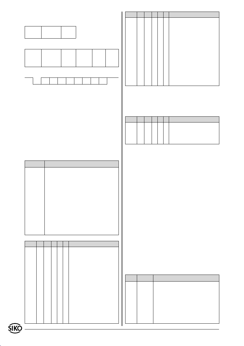
There are 2 telegram length:
3 Byte:
Address
Command Check
Byte
Byte
6 Byte:
Address
Command Data
Byte
Byte
Low
Data
Byte
Middle
Data
Byte
High
check
Byte
The address byte is composed as follows:
1 0 A0 A1 A2 A3 A4 0 RR L 1
Start LSB MSB Stop
The test byte results from an EXOR-interconnection
of the remaining two or five bytes of the telegram.
A0 ... A4: binary coded address 1 ... 31;
adress 0 defined for master
RR: broadcast Bit = 1; command valid for
all devices; devices do not reply
L: length Bit: 1 = short telegram (3 bytes)
0 = Long telegram (6 bytes)
Parameter: 19200 baud, no Parity, 8 bit,
1 Start bit, 1 Stop bit
Column: Signification:
Hex: hexadezimal value of the command
TX: length of telegram from master to
AEA111/1
RX: length of telegram from AEA111/1 to
master
S: transmitted parameter is permanently
stored in the sensor
P: for this command programming mode
has to be activated (command 0x32;
0x33)
R: this command can be broadcasted
Hex TX RX S P R Function
0x16 3 6 - - - read out position value
0x18 3 6 - - - read out calibration value
0x1b 3 6 - - - read out device's characteristics
0x1d 3 6 - - - read out counting direction
0x28 6 6 S P - program calibration value
0x2d 6 6 S P - program counting direction
D-Byte 1: identifier 26 (dec.);
D-Byte 2: software version
D-Byte 3: hardware version
value = 0: "up" (+)
value = 1: "down" (-)
value to which the position value
is set when the device is calibrated (command 0x48)
value = 0: "up" (+)
value = 1: "down" (-)
Hex TX RX S P R Function
0x32 3 3 - - - programming mode "ON"
0x33 3 3 - - - programming mode "OFF"
0x3a 3 6 - - - send system status
0x3b 3 3 - - - cancel system status
0x48 3 3 S P - position value is set to calibration
0x4F 3 3 - - R freeze position value
Default
system status bytes 2 and 3 are
being deleted
value
position value is freezed; deactivated when positional value is
read out. Used for synchronizing
the readout of several devices.
Error messages
The slave (AEA111/1) recognizes transmission or
input errors and then issues the following error messages:
Hex TX RX S P R Function
82 Hex - 3 - - - check sum data transmission error
84 Hex - 3 - - - invalid or unknown command
88 Hex - 3 - - - invalid value (parameter program-
ming)
Synchronisation:
Byte/ telegram synchronisation is made via "Timeout": the distance between each byte of a telegram must not exceed 10ms. If a device does not
respond, the master may only send another telegram after 30ms at the earliest.
Telegram example:
Master requests position value from device 7.
Master sends (hex): 87 16 91
short telegram to address 7 (87h); read out posi-
tion value (16h); check byte (91h)
AEA111/1 replies (hex): 07 16 03 02 00 10
Long telegram from address 7 (07h); read out position value (16h); value 203h = 515 dec (03 02
00h); check byte (10h).
11. Overview of bit assignment of the
individual registers
11.1 8bit System status register
Bit Default Remarks
0 0 ERROR-Bit: invalid distance sen-
1 0 ERROR-Bit: position jump occur-
2 0 CONFIG INPUT Bit: is set as long
sor-strip or strip break
red
as 24V are applied tothe configuration input.
18 AEA111/1 Datum 25.01.2008 Art.Nr. 84155 Änd. Stand 245/07
Page 19
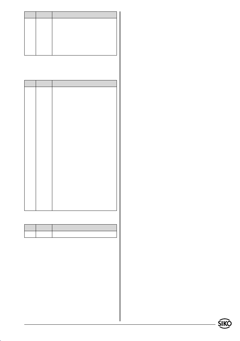
Bit Default Remarks
3 0 ERROR Bit: sensor connection line
broken
4 0 ALIGNMENT FLAG: is set during
sensor alignment
5 0 ERROR-Bit: Speed measurement
6...7 - -
The error bits 0, 1, 3 remain set until after proper
acknowledgement.
11.2 8bit configurations register-0
Bit Default Remarks
0 0 If set, an identifier is set via RS485
(if active) after turning on +24V
-> start message
1 0 Counting direction:
0 = POSITIV;
1 = NEGATIV
2 1 SSI code:
0 = binary
1 = Gray
3 0 (for internal purposes: HALL de-
coding)
4 0 position value monitoring:
0 = speed measurement
1 = Millimetre jump
5 1 Position value filter:
0 = OFF
1 = ON
6 1 Cable break detection:
0 = OFF
1 = ON
7 0 not used
absolute position. Changes of the SW1 switches
and on the configuration input are only evaluated
after a startup delay of ~0.5s.
13. Trouble shooting
Below there are some typical errors which may occur during installation and operation:
The AEA111/1 is not or incorrectly connected
•
(pin connection see chapter 5).
Tolerance for the gap between magnetic sensor
•
and magnetic strip not opserved over the total
travel distance. Sensor touches strip.
Cable squeezed/ interrupted / cut by sharp
•
edges.
Sensor and strip are aligned incorrectly towards
•
each other.
Wrong measuring values due to EMC interferences
•
(see chapter 5)
The operating mode set does not correspond with
•
the hardware connected.
11.3 8Bit configuration register-1
Bit Default Remarks
0...7 0 (for internal purpose)
12. Configuration input of the
AEA111/1
As soon as +24VDC are applied to the configuration input, the SSI interface and the electronics
unit for sensing absolute information from the
sensor head are deactivated after a short debouncing delay (~1sec.). This function can be used for
minimizing the unavoidable signal noise on the
sensor connection line and the associated anolog sin/cos outputs. This state is not evaluated
if +24VDC are already applied to the configuration input when switching on the AEA111/1 since
otherwise it would not be possible to scan the
AEA111/1 Datum 25.01.2008 Art.Nr. 84155 Änd. Stand 245/07 19
Page 20
SIKO GmbH
Werk / Factory:
Weihermattenweg 2
79256 Buchenbach-Unteribental
Postanschrift / Postal address:
Postfach 1106
79195 Kirchzarten
Telefon/Phone +49 7661 394-0
Telefax/Fax +49 7661 394-388
E-Mail [email protected]
Internet www.siko.de
Service [email protected]
20 AEA111/1 Datum 25.01.2008 Art.Nr. 84155 Änd. Stand 245/07
 Loading...