

Siklu EtherHaul, EtherHaul 600 TX, EtherHaul 600 T Quick Setup Manual

: B
e 1
Safety Notes
This Quick Guide is intended as a handy reference for setting up the EtherHaul
EtherHaul
ODU with integrated
antenna. This guide does not replace the full manual; please refer to the “ Installation User Manual”
full installation and setup details.
The Installation and maintenance of this link should be performed by service personnel who are properly traine
and certified to carry out suc
h activities. Make sure to disconnect all power cables before service!
ODU must be grounded using min 16AWG cable or according to local electrical code.
1
Mounting Bracket
1. Elevation Lock Bolts (1 additional bolt at opposite side of the mount)
2. Elevation Fine Adjustment Screw (+10°÷-60°)
3. Azimuth Fine Adjustment Screw (±10°)
4. ODU Mounting Hooks
5. Azimuth Lock Bolts (2 additional bolts at opposite side of the mount)
6. Worm Clamp
2
Q
uick Setup
Guide
P/N: IDOC012, Rev
Description: EH-QSINST-12 issu
Preparing the ODU and the Bracket
Before installing the ODU, the correct ODU Bracket Adapter has to be attached to the mounting bracket.
1. Unpack the Mounting Bracket and attach the ODU Bracket Adapter to the Mounting Bracket using 4 Hex
screws.
2. Use 3 Hex screws and apply them to the back of the ODU, assuring minimum gap
of ~5mm, to allow sliding them on the Mounting Bracket.
Note: the Triangular
adapter that can be found in the Bracket package is not used
with this ODU model.
3
EtherHaul
Small Form Factor
for
Support Contacts
Contact your local distributor for the technical support.
Technical support for Siklu’s direct customers: support@siklu.com
Download your copy of the product’s user manuals from ftp://ftp.siklu.com (user: installmanual, password: siklu).
Watch us install and setup a link at www.youtube.com (search: Siklu Etherhaul Installation)
Siklu Communication Ltd. 43, Hasivim St, Petach-Tikva 49517, Israel
11
Basic Configuration using the Web-Based Management
1.Launch an Internet browser and enter the ODU’s IP address in the address bar. For the default IP address enter:
https://192.168.0.1. Default read/write access: admin, admin).
2. Use the Quick Config wizard to configure the basic system parameters for both local and remote systems.
3. System section: set system information such as Name, Date (YYYY
.MM.DD) and Time (HH:MM:SS).
4.Radio section: set RF parameters.
Channel Width (MHz) – 500MHz. Note that on product’s specs.
Frequency (MHz) – picklist. Default value is 57875. Rx frequency will be configured accordingly.
Make sure to select a channel that is approved for use by local regulation.
Tx Power (dBm) – ODU’s transmit power (+5 to -35dBm). Default= +5dBm. Reduce the Tx power in case of
short links, making sure the RSSI at the remote ODU does not exceed -35dBm (overload threshold).
Mode – Default value is Adaptive (Adaptive Bandwidth, Code and Modulation), meaning the ODU will switch
to the highest modulation profile available by data-rate license and link condition.
Transmit Asymmetry – Default value is symmetric configuration: 50% for Tx and Rx (50tx-50rx). When
selecting asymmetric configuration (75%/25% ), the Role will be changed from Auto and will be
set automatically (Master for 75tx-25rx and Slave for 25tx-75rx ). Role settings can
be found in the Radio Advanced Settings section.
5. Eth Ports: set Ethernet ports configuration such as enable/disable, a
uto-negotiation and Speed/Duplex.
6. Network section: set IP address (static or DHCP, IPv4 or IPv6) and SNMP attributes.
IP Address – set up to 4 IP addresses: IP, Prefix-length (in mask bits) and VLAN for management (VLAN
0=untagged). It is recommended to leave default IP as IP #1 and configure the new IP address as IP #2.
Default gateway
SNMP Manager – set SNMP trap destination (up to 5 manager can be defined).
7. Click Apply. Settings will be applied for local and remote systems.
Note: when changing RF parameters the link will go down and recover after ~1 minute.
Note: changing IP address will terminate your connection. Reconnect and launch the Web management using the
new IP address.
8.To save the system configuration, click Save
Configuration on the Main page for local and remote systems.
Note: System will lose its configuration upon next reset if you do not click Save Configuration, saving the currently
running configuration to the startup configuration, for local and remote systems.
9. To monitor radio link status, use the Main (or Radio) page:
Status – Displays the radio link status (Up or Down).
RSSI (dBm) – displays the Receiver Signal Strength Indicator displays the received signal level.
CINR (dB) – displays the Carrier to Interference + Noise ratio, which indicates the radio link’s signal quality. In
normal conditions, CINR≥20 indicates a good signal quality.
Mode – when working in Adaptive mode, the current modulation profile is displayed. Modulation profile
depends on link status (CINR) and loaded data-rate license.
10. To view and set the loaded license configuration, use the System page under the Licensing section.
10
other channel width options depend
d
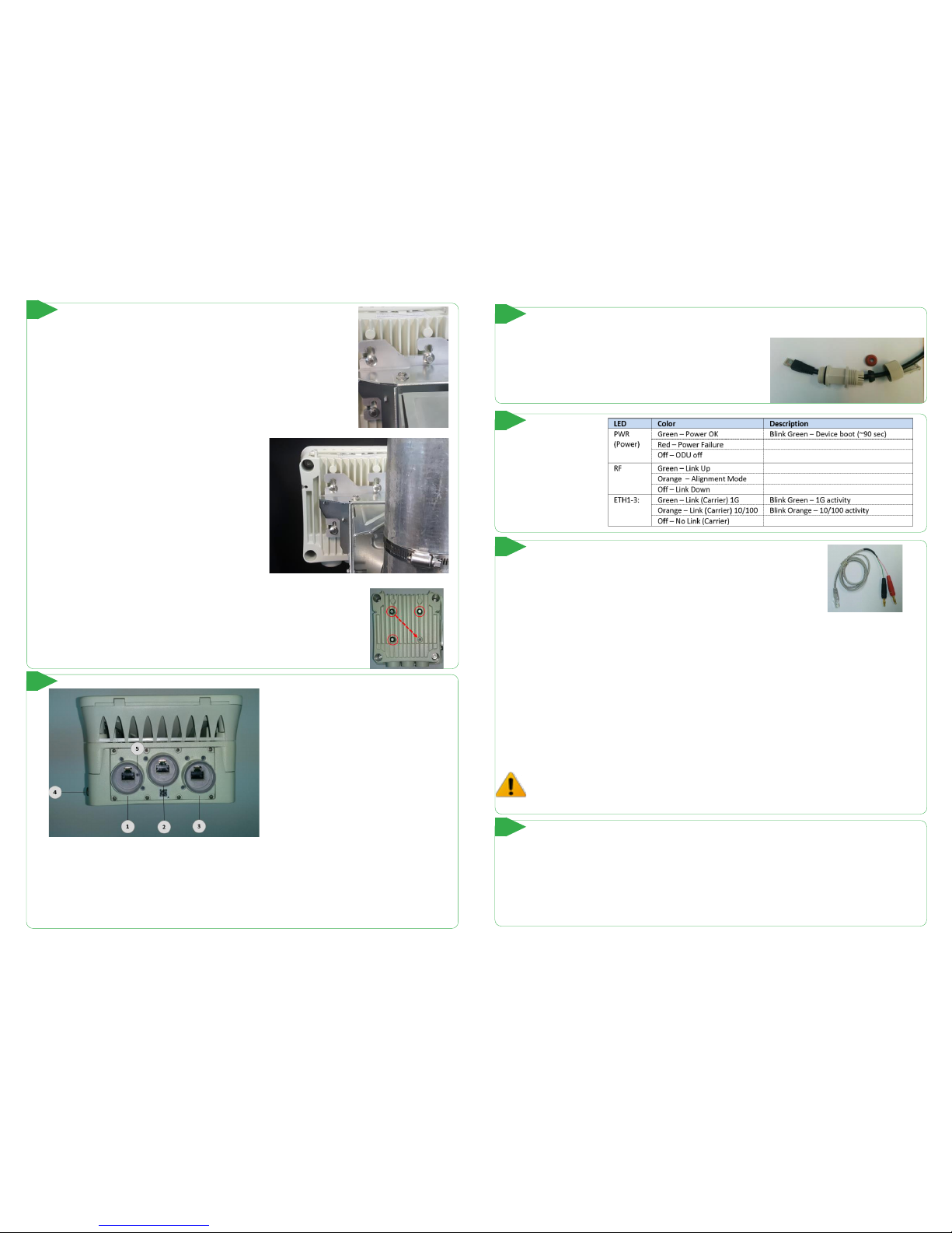
Connecting the Cables
1. Eth Port #1 (PoE In)
2. Eth Port #2
3. Eth Port #3 (and Alignment RSSI Adapter
output for antenna alignment)
4. Ground Point (GND)
5. Alignment mode toggle and Restore Factory
Defaults (press for more than 8 seconds to
restore factory defaults)
1. All cabling connected to the ODU should be outdoor-grade, with UV protection.
2. Shielded outdoor Cat5e cables terminated with metalli
c RJ45 connectors must be used.
3. Connect the ground cable to the ODU GND point.
Note: Connect the ground cable to the ODU BEFORE mounting it!
4. Power up the ODU using 802.3at Power over Ethernet (connection available port 1 only).
5
Mounting the ODU and Bracket
1. Attach the ODU to the Mounting Bracket by sliding it to the 3 Mounting Hooks
and lock the bolts.
2.In order to allow free movement during alignment,
unlock the Elevation and Azimuth Lock Bolts and position
the bracket at 0 degrees.
3. Mount the ODU and the Mounting Bracket on a fixed
reinforced steel mounting pole with 2-4 inches diameter.
4. Use worm clamps (steel ba
nd) to secure the bracket to
the mounting pole.
5. Note that ODUs are shipped in Vertical polarization.
Note: In case elevation of more than +10°is needed (when shooting upwards), the
mounting bracket should be installed up-side-down. In this case, relocate the
Hex screw so it will fit the new bracket position. Install the ODU so the
connectors will still face downwards.
4
System LEDs
7
Initial System Setup
1.Disconnect the DVM cable and reinsert and tighten the Eth3 port protective seal cap or connect data cable.
2.If Alignment Mode was used, reboot both ODUs by disconnecting the power.
3. Confirm that the RF LED color indicator on both ODUs will turn Green, indicating that the radio link is Up.
The EtherHaul link can now pass traffic and management between the ports and over the r
adio link.
For further radio link configuration, connect to the ODU using the web-based management.
9
Aligning the Ant ennas
1.Perform a coarse Azimuth and Horizontal alignment using a line-of-sight
visual check with the remote ODU. Lock the Mounting Bracket to the pole
using the worm-clamps.
2. Power up the ODUs and connect the RJ45 connector of the supplied
Alignment RSSI Adapter to Eth3. Alignment RSSI Adapter
3. Read the receive level (RSSI) using the DVM. The voltage reading will be betw
een 0 to 1Vdc, indicating the RSSI
in dBms (for example 0.45V=-45dBm).
4. Perform fine Azimuth and Elevation alignment using the fine adjustment bolts, identifying the main lobe until
the expected receive level is achieved (within +/-4dB). Align the ODUs in turns till optimal alignment.
5. Once the optimum position has been achieved, tighten the azimuth and elevation lock bolts on first ODU.
6. Use
the DVM to verify that the received signal level has not degraded during locking.
7. Repeat steps 5-6 on the second ODU.
Antenna alignment is now complete.
Antennas can be aligned also when set to Alignment Mode. Switch both sides to Alignment mode only in
cases where you fail to achieve optimal alignment after considerable tries. Switching the ODU to
Alignment mode can be done using the web-based m
anagement or by short-press on the push button on
Eth1 port, toggling the ODU between Adaptive and Alignment modes (following system reboot).
8
Weatherproofing the Connectors
The provided protective All-Weather Shells fit cables from 3.5mm to 9.0mm diameter.
1. Thread the cable and tight the shell to the ODU firmly by hand
(do not use tools).
2. Insert the rubber gasket snugly and tight the connector lock
3. When removing the All-Weather Shell, unlock the gland first
before removing the shell.
6
 Loading...