

Page 1
© ALL RIGHTS RESERVED TO SIKLU COMMUNICATION LTD.
EtherHaul™ 8000 Series
Gigabit Ethernet Wireless Solution
Installation, Operation, and
Maintenance Manual
EH8000-I&O-01, Issue 2
July 2018
Page 2

EtherHaul™ 8000 Installation, Operation and Maintenance Manual
Page 2
Trademarks
Siklu, the Siklu logo, and EtherHaul™ are all trademarks of Siklu Communication Ltd.
All other product names and trademarks mentioned in this document are trademarks or
registered trademarks of their respective companies.
Copyrights
Copyright © 2018 Siklu Communication Ltd. All rights reserved.
No part of this publication may be reproduced or distributed in any form or by any
means, or stored in a database or retrieval system, without the prior written consent of
Siklu.
Disclaimers
The information contained in this document is subject to change without notice.
Siklu assumes no responsibility for any errors that may appear. Siklu makes no
warranties, expressed or implied, by operation of law or otherwise, relating to this
document, the products or the computer software programs described herein.
This document was originally written in English. Please refer to the English language
version for a full and accurate description of all products and services described herein.
Page 3

EtherHaul™ 8000 Installation, Operation and Maintenance Manual
Page 3
Safety and Regulatory Notices
The following are mandatory notices for installation and operation of EtherHaul™
Wireless Backhaul Link. Indications appearing here are required by the designated
government and regulatory agencies for purposes of safety and compliance.
General
Do not install or operate this System in the presence of flammable gases or fumes.
Operating any electrical instrument in such an environment is a safety hazard.
European Commission
This product has been designed to comply with CE markings in accordance with the
requirements of European Directive 1995/5/EC.
This product has been designed to comply with the requirements of European
Directives.
This equipment must be permanently earthed for protection and functional purposes.
To make a protective earth connection, use the grounding point located on the ODU
using a minimum amount of 16AWG grounding cable or according to local electrical
code.
This apparatus is intended to be accessible only to authorized personnel. Failure to
prevent access by unauthorized personnel will invalidate any approval given to this
apparatus.
This product is in full compliance with the following standards:
RF EN 302 217-3 1.3.1
E-Band FCC part 101
EMC EN 301 489-4
Safety IEC 60950
Operation EN 300 019-1-4 Class 4.1E
Storage EN 300 019-1-1 Class 1.2
Transportation EN 300 019-1-2 Class 2.2
Page 4

EtherHaul™ 8000 Installation, Operation and Maintenance Manual
Page 4
FCC/IC Regulatory Statements
This equipment has been tested and found to comply with the limits for a Class B digital
device, pursuant to Part 15 of the FCC Rules and IC RSS standards. These limits are
designed to provide reasonable protection against harmful interference in a re sidential
installation. This equipment generates uses and can radiate radio frequency energy and,
if not installed and used in accordance with the instructions, may cause harmful
interference to radio communications. However, there is no guarantee that int erference
will not occur in a particular installation. If this equipment does cause harmful
interference to radio or television reception, which can be determined by turning the
equipment off and on, the user is encouraged to try to correct the interference by one
or more of the following measures:
Reorient or relocate the receiving antenna.
Increase the separation between the equipment and receiver.
Connect the equipment into an outlet on a circuit different from that to
which the receiver is connected.
Consult the dealer or an experienced radio/TV technician for help.
Note:
Changes or modifications to this equipment not expressly approved by Siklu LTD or
the party responsible for compliance could void the user's authority to operate the
equipment.
Caution:
Outdoor units and antennas should be installed ONLY by experienced installation
professionals who are familiar with local building and safety codes and, wherever
applicable, are licensed by the appropriate government regulatory authorities.
Failure to do so may void the product warranty and may expose the end user or the
service provider to legal and financial liabilities. Siklu LTD and its resellers or
distributors are not liable for injury, damage or violation of regulations associated
with the installation of outdoor units or antennas.
Prudence: Les unités extérieures et les antennes doivent être installeés par des professionnels
d'installation expérimentés qui sont familiers avec les normes locales et les codes de
sécurité et, si applicable, sont agréées par les autorités gouvernementales de
réglementation. Ne pas le faire peut annuler la garantie du produit et/ou exposer
l'utilisateur ou le fournisseur de services à des obligations juridiques et financieres. Les
revendeurs ou distributeurs de ces équipements ne sont pas responsables des blessures,
des dommages ou violations des règlements liés à l'installation des unités extérieures ou
des antennes. L'installateur doit configurer le niveau de puissance de sortie des antennes
conformément aux réglementations nationales et au type d'antenne.
Page 5

EtherHaul™ 8000 Installation, Operation and Maintenance Manual
Page 5
About this Document
This document is the Installation, Operation and Maintenance manual for Siklu’s
EtherHaul™ 8000 series wireless link product line.
Note:
Features and functionality described in this document may be available for specific
product models or starting from specific SW version.
Please review the individual product’s release notes to verify if a specific feature is
supported in the product you use.
Applicable Products and Releases
E-Band
o EH-8010FX, minimum SW release 10.0.0
Audience
This document assumes a working knowledge of wireless backhaul platforms and their
operating environments.
This document is intended for use by all persons who are involved in planning, installing,
configuring, and using the EtherHaul™ system.
Conventions
The following conventions are used in this document in order to make locating, reading,
and using information easier.
Special Attention
Hint:
Informs you of a helpful optional activity that may be performed at the current
operating stage.
Note:
Provides important and useful information.
Page 6

EtherHaul™ 8000 Installation, Operation and Maintenance Manual
Page 6
Caution:
Describes an activity or situation that may or will interrupt normal operation of the
system, one of its components, or the network.
Text Conventions
Document References
Italicized text is used to reference sections or
chapters in this document. In many cases, references
use clickable hypertext links that enable immediate
access to referenced objects.
Command Input
Monospace text is used to help delineate command
line user input or text displayed in a command
window.
Page 7

EtherHaul™ 8000 Installation, Operation and Maintenance Manual
Page 7
TABLE OF CONTENTS
1 Introduction to the EtherHaul™ System ................................................... 13
1.1 Main Features ................................................................................................................14
1.2 Functional Description ..................................................................................................16
2 Installing the Radio Link ............................................................................ 17
2.1 Preparing the Site ..........................................................................................................17
2.1.1 Physical and Environmental Requirements ......................................................18
2.1.2 Cabling Requirements ......................................................................................18
2.2 Package Content ............................................................................................................19
2.3 Unpacking the Radio .....................................................................................................19
2.4 Required Tools ..............................................................................................................20
2.5 Preparing for Installation ...............................................................................................20
2.6 Installing the Radio with a 0.5ft/1ft Antenna ................................................................21
2.6.1 Attaching the Antenna to the Radio..................................................................21
2.6.2 Mounting using 1ft Mounting Kit ....................................................................22
2.7 Installing the Radio with a 2ft Antenna .........................................................................24
2.7.1 Attaching the 2ft Adapter to the Radio .............................................................24
2.7.2 Attaching the Radio to the 2ft Antenna ............................................................24
2.8 Connecting the Cables ...................................................................................................26
2.8.2 Grounding the Radio ........................................................................................28
2.8.3 Preparing the Cables .........................................................................................29
2.8.4 Powering up the Radio .....................................................................................30
2.9 System LEDs .................................................................................................................30
2.10 Aligning the Antenna.....................................................................................................31
2.10.1 Switching the Radio to Alignment Mode .........................................................31
2.10.2 Performing the Alignment ................................................................................31
2.11 Link Up Verification .....................................................................................................34
3 Setup and Monitoring Using the Web-based Management ..................... 35
3.1 Connecting to the Radio Using the Web-Based Management ......................................36
3.2 Connecting to the Radio Using the Command Line Interface .......................................37
3.3 Web-Based Management Main Page ............................................................................38
3.4 Quick Configuration Wizard .........................................................................................39
3.5 General Configuration Commands ................................................................................39
3.5.1 Apply ................................................................................................................39
3.5.2 Save Configuration ...........................................................................................40
3.5.3 Rollback ............................................................................................................40
Page 8

EtherHaul™ 8000 Installation, Operation and Maintenance Manual
Page 8
3.5.4 Reboot ...............................................................................................................40
3.6 Copy To Remote ............................................................................................................41
4 Radio Configuration and Monitoring ......................................................... 42
4.1 Settings ..........................................................................................................................42
4.2 Advanced Settings .........................................................................................................44
4.3 Maintenance ..................................................................................................................45
4.4 Modulation Table ..........................................................................................................46
4.5 Statistics .........................................................................................................................47
4.6 CLI Commands .............................................................................................................47
5 Ethernet Ports Configuration and Monitoring .......................................... 48
5.1 Settings ..........................................................................................................................48
5.2 Advanced Settings .........................................................................................................49
5.3 Maintenance ..................................................................................................................50
5.4 Statistics .........................................................................................................................50
5.5 CLI Commands .............................................................................................................51
6 System Configuration and Monitoring ...................................................... 52
6.1 Settings ..........................................................................................................................52
6.2 Advanced Settings .........................................................................................................53
6.3 Maintenance ..................................................................................................................54
6.3.1 File Transfer .....................................................................................................54
6.3.2 SW Upgrade .....................................................................................................55
6.3.3 Licensing ..........................................................................................................56
6.3.4 Scripts ...............................................................................................................58
6.3.5 Configuration Management ..............................................................................59
6.4 Event Configuration ......................................................................................................59
6.5 CLI Commands .............................................................................................................60
7 Network Configuration and Monitoring .................................................... 62
7.1 General ..........................................................................................................................62
7.1.1 IP Address ........................................................................................................62
7.1.2 Default Gateway and Static Routes ..................................................................63
7.1.3 SNMP Managers...............................................................................................63
7.1.4 NTP ...................................................................................................................64
7.2 Advanced Settings .........................................................................................................65
7.2.1 Management Access List ..................................................................................65
7.2.2 SNMP Agent ....................................................................................................65
7.2.3 SNMP V3 Users ...............................................................................................66
7.2.4 Syslog Server ....................................................................................................66
7.3 Maintenance ..................................................................................................................67
Page 9

EtherHaul™ 8000 Installation, Operation and Maintenance Manual
Page 9
7.3.1 Connectivity .....................................................................................................67
7.3.2 Iperf Test ..........................................................................................................67
7.3.3 ARP Table ........................................................................................................68
7.4 Users Administration .....................................................................................................69
7.4.1 Users .................................................................................................................69
7.4.2 Password Strength ............................................................................................69
7.5 LLDP .............................................................................................................................70
7.5.1 LLDP Configuration .........................................................................................70
7.5.2 LLDP Status .....................................................................................................71
7.6 CLI Commands .............................................................................................................72
8 Ethernet Services Configuration and Monitoring .................................... 75
8.1 Bridge Architecture .......................................................................................................75
8.2 Bridge Ports ...................................................................................................................76
8.3 Bridge Rules ..................................................................................................................77
8.4 Maintenance ..................................................................................................................78
8.5 CLI Commands .............................................................................................................79
9 Administration ............................................................................................ 80
9.1 TACACS+/RADIUS Users Administration ..................................................................80
9.1.1 AAA Description ..............................................................................................80
9.1.2 Authentication Modes .......................................................................................81
9.1.3 TACACS Authentication Mode .......................................................................81
9.1.4 Radius Authentication Mode ............................................................................83
9.2 CLI Commands .............................................................................................................84
9.3 SNMPv3 Users Configuration .......................................................................................85
9.4 Monitoring CLI Sessions ...............................................................................................86
10 Diagnostics ................................................................................................. 87
10.1 Troubleshooting Process................................................................................................87
10.2 System LEDs .................................................................................................................88
10.3 Alarms ...........................................................................................................................89
10.4 Performance Statistics ...................................................................................................92
10.5 Loopbacks ......................................................................................................................92
10.5.1 Loopbacks Diagram ..........................................................................................92
10.5.2 Ethernet Line Loopbacks ..................................................................................93
10.5.3 Radio (RF) Loopback .......................................................................................93
10.5.4 CLI Commands.................................................................................................94
11 Statistics ...................................................................................................... 96
11.1 Radio (RF) Statistics Monitoring ..................................................................................96
11.1.1 RF Statistics Summary .....................................................................................96
Page 10

EtherHaul™ 8000 Installation, Operation and Maintenance Manual
Page 10
11.1.2 RF Statistics Summary – 30 days .....................................................................97
11.1.3 RF Statistics ......................................................................................................97
11.2 Bandwidth Utilization Statistics ....................................................................................98
11.3 Ethernet Statistics ..........................................................................................................99
11.4 CLI Commands ...........................................................................................................100
Page 11

EtherHaul™ 8000 Installation, Operation and Maintenance Manual
Page 11
TABLE OF FIGURES
Figure 1-1 Hitless Adaptive Bandwidth, Coding and Modulation .......................................... 15
Figure 1-2 EH-8000 Series Functional Block Diagram ........................................................... 16
Figure 2-1 Attaching the Antenna to the Radio (0.5ft and 1ft Antennas) ................................ 21
Figure 2-2 Attaching the Quick Release Plate andSetting Polarization ................................... 21
Figure 2-3 1ft Mounting Kit Components ............................................................................... 22
Figure 2-4 Quick Release Hooks ............................................................................................. 23
Figure 2-5 2ft Adapter ............................................................................................................. 24
Figure 2-6 Radio Installed on a 2ft Antenna ............................................................................ 25
Figure 2-7 Front Panel Details ................................................................................................. 26
Figure 2-8 DC Terminal Block ................................................................................................ 27
Figure 2-9 Grounding Scheme ................................................................................................. 29
Figure 2-10 All-Weather Connecting Cable Shell Assembly .................................................. 30
Figure 2-11 1ft Antenna Visual Alignment Tool ..................................................................... 32
Figure 3-1 Launching the Web-Based Management ............................................................... 36
Figure 3-2 Entering Username and Password .......................................................................... 36
Figure 3-3 Web-Based Management Main Page ..................................................................... 36
Figure 3-4 Launching CLI ....................................................................................................... 37
Figure 3-5 Copy To-Remote icon ............................................................................................ 41
Figure 4-1 Radio Page: Settings .............................................................................................. 42
Figure 4-2 Radio Page: Settings in Alignment Mode .............................................................. 43
Figure 4-3 Radio Page: Advanced Settings ............................................................................. 44
Figure 4-4 Radio Page: Maintenance ....................................................................................... 45
Figure 4-5 Radio Page: Modulation Table ............................................................................... 46
Figure 4-6 Radio Page: Statistics ............................................................................................. 47
Figure 5-1 Eth Ports Page: Settings ......................................................................................... 48
Figure 5-2 Eth Ports Page: Advanced Settings ........................................................................ 49
Figure 5-3 Eth Ports Page: Maintenance ................................................................................. 50
Figure 5-4 Eth Ports Page: Statistics ........................................................................................ 50
Figure 6-1 System Page: Settings ............................................................................................ 52
Figure 6-2 System Page: Advanced Settings ........................................................................... 53
Figure 6-3 System Page: Maintenance – File Transfer ............................................................ 54
Figure 6-4 System Page: Maintenance – SW Upgrade ............................................................ 55
Figure 6-5 System Page: Maintenance – Licensing ................................................................. 56
Figure 6-6 System Page: Maintenance – Scripts ..................................................................... 58
Figure 6-7 System Page: Maintenance – Configuration Management .................................... 59
Figure 6-8 Network Page: Event Configuration ...................................................................... 59
Page 12

EtherHaul™ 8000 Installation, Operation and Maintenance Manual
Page 12
Figure 7-1 Network Page: General – IP Address ..................................................................... 62
Figure 7-2 Network Page: General – Default Gateway ........................................................... 63
Figure 7-3 Network Page: General – SNMP Managers ........................................................... 63
Figure 7-4 Network Page: General – NTP ............................................................................... 64
Figure 7-5 Network Page: Advanced Settings – Management Access List............................. 65
Figure 7-6 Network Page: Advanced Settings – SNMP Agent ............................................... 65
Figure 7-7 Network Page: Advanced Settings – SNMP V3 Users .......................................... 66
Figure 7-8 Network Page: Advanced Settings – Syslog Server ............................................... 66
Figure 7-9 Network Page: Maintenance – Connectivity .......................................................... 67
Figure 7-10 Network Page: Maintenance – Iperf Test ............................................................. 67
Figure 7-11 Network Page: Maintenance – ARP Table .......................................................... 68
Figure 7-12 Network Page: Users Administration – Local Authentication ............................. 69
Figure 7-13 Network Page: Advanced Settings – Password Strength ..................................... 69
Figure 7-14 Network Page: LLDP Configuration.................................................................... 70
Figure 7-15 Network Page: LLDP Status ................................................................................ 71
Figure 8-1 Services Page: Settings .......................................................................................... 75
Figure 8-2 Bridge Ports Settings .............................................................................................. 76
Figure 8-3 Bridge Rule ............................................................................................................ 77
Figure 8-4 Services Page: Maintenance ................................................................................... 78
Figure 9-1 Network Page: Users Administration – TACACS ................................................. 81
Figure 9-2 Network Page: Users Administration – Radius...................................................... 83
Figure 9-3 Network Page: Advanced Settings – SNMP V3 Users .......................................... 85
Figure 10-1 System Loopback Points ...................................................................................... 92
Figure 10-2 Ethernet Line Loopback ....................................................................................... 93
Figure 10-3 RF Loopback ........................................................................................................ 94
Figure 11-1 Statistics Page: RF Statistics Summary ................................................................ 96
Figure 11-2 Statistics Page: RF Statistics Summary – 30 days ............................................... 97
Figure 11-3 Statistics Page: RF Statistics ................................................................................ 97
Figure 11-4 Statistics Page: Bandwidth Utilization Statistics ................................................. 99
Figure 11-5 Statistics Page: Ethernet Statistics ....................................................................... 99
Page 13

EtherHaul™ 8000 Installation, Operation and Maintenance Manual
Page 13
1 Introduction to the EtherHaul™ System
This chapter provides a brief overview of the EtherHaul™ product line.
The EtherHaul™ product line delivers carrier-grade wireless point-to-point gigabit
Ethernet services utilizing the 57-71GHz unlicensed V-band and the light-licensed 7176/81-86GHz E-band spectrum. The EtherHaul™ is based on Siklu’s revolutionary
integrated-silicon technology, which results in a highly reliable, zero footprint, and lowcost radio.
The EtherHaul™ 8000 series is Siklu’s ultra high capacity radios, offeing 10 Gigabit
throughput and enhanced Hitless Adaptive Bandwidth, Coding and Modulation for
maximum spectral efficiency, and services availability. It supports network
synchronization, advanced OAM&PM tools and ring protection optimized for both small
cell and mobile backhaul. It features multiple GbE interfaces, including optical,
supporting complex network topologies, such as daisy chain, ring, and mesh. The
multiple ports enable also colocation installation and leveraging the infrastructure for
additional fixed services delivery. The EtherHaul™ is fast, simple and inexpensive to
deploy.
EtherHaul™ as the ideal solution for mobile backhaul and business services delivery
features:
Field proven technology
Reduced TCO and fast ROI
All-outdoor invisible footprint
o Small and light
o Quick and easy to install
Spectral efficient
o Wide range of bandwidth option
o Hitless Adaptive Bandwidth Coding and Modulation for high availability
Advanced layer-2 features:
o MEF-compliant services and QoS
o VLAN & Provider Bridge with 16K jumbo frames support
Clear separation between multiple services with QoS
Enables QoS aware MPLS services delivery
o SLA assurance
Advanced AES encryption for secured street level deployments
Page 14

EtherHaul™ 8000 Installation, Operation and Maintenance Manual
Page 14
Highly-scalable, the EtherHaul™ products are software-upgradable to support future
Layer 2.5/3 networking and routing capabilities as networks evolve to flat-IP topologies.
1.1 Main Features
Siklu’s EtherHaul™ wireless backhaul radio link operates in the lightly licenses
interference free E-band spectrum, which provides clear technological and economic
advantages over the existing lower frequency bands. Taking advantage of the new
spectrum, the EtherHaul™ enables easy migration to support 10 Gigabit throughput,
enabling operators to enhance bandwidth capacity on a “pay as you grow” basis.
Supporting point-to-point, daisy chain, ring, and mesh configurations, the EtherHaul™
system offers carrier class availability and services.
The following are some of the main features of the EtherHaul ™ (availability of features
depends on platform):
All-Outdoor Packet Radio
Operates in the light-licensed 71-76/81-86 GHz E-Band, FDD
Up to 10 Gbps throughput
High gain narrow beam-width directional antennas
Low latency
Highest Spectral Efficiency
250, 500, 1250 or 2000 MHz channel bandwidth (model dependent)
Advanced hitless/errorless Adaptive Bandwidth, Coding and Modulation
(ABCM) for a large dynamic range
Configurable center frequency across the entire band
Carrier Ethernet Inside:
Integrated Gigabit Ethernet switch
Advanced bandwidth-aware QoS capabilities
SyncE, IEEE 1588TC and optimized transport of IEEE 1588 (model dependent)
Ring, mesh and daisy chain topologies for carrier grade availability and
resiliency
Standard-based for seamless integration into existing networks and multi-
vendor interoperability
Multi-vendor interoperability approved
Carrier Grade:
CLI, SNMP and web-based local and remote management
Extremely high reliability with very high MTBF
Page 15
EtherHaul™ 8000 Installation, Operation and Maintenance Manual
Page 15
Designed for ultra-low MTTR without the need for antenna realignment
Green Design:
Zero footprint, all-outdoor, extremely light weight
low power consumption
IEEE 802.3at+ complaint Power over Ethernet
Quick and Easy Installation
Rapid and flexible deployment
Precise antenna alignment
Minimal site preparation
Security
Advanced AES encryption and security (model dependent)
Narrow and secure beam-width
Adaptive Bandwidth, Coding and Modulation
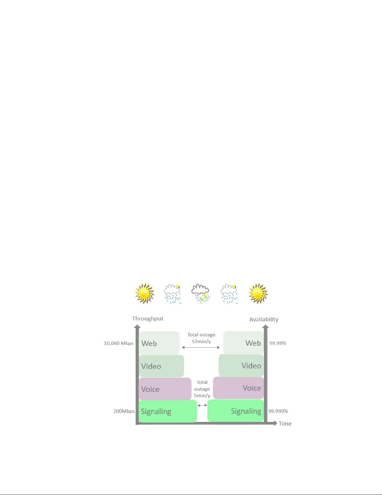
The EtherHaul™ family implements hitless/errorless adaptive bandwidth, coding and
modulation adjustment to optimize the over-the-air transmission and prevent weatherrelated fading from disrupting traffic on the link. The EtherHaul™ can gain up to 21 dB in
link budget by dynamically adapting: Modulation, FEC coding rates, and channel
bandwidth maintaining the high priority traffic using quality of service advanced
mechanism and dropping the traffic according to the QoS priority defined by the user.
Figure 1-1 Hitless Adaptive Bandwidth, Coding and Modulation
Page 16
EtherHaul™ 8000 Installation, Operation and Maintenance Manual
Page 16
1.2 Functional Description
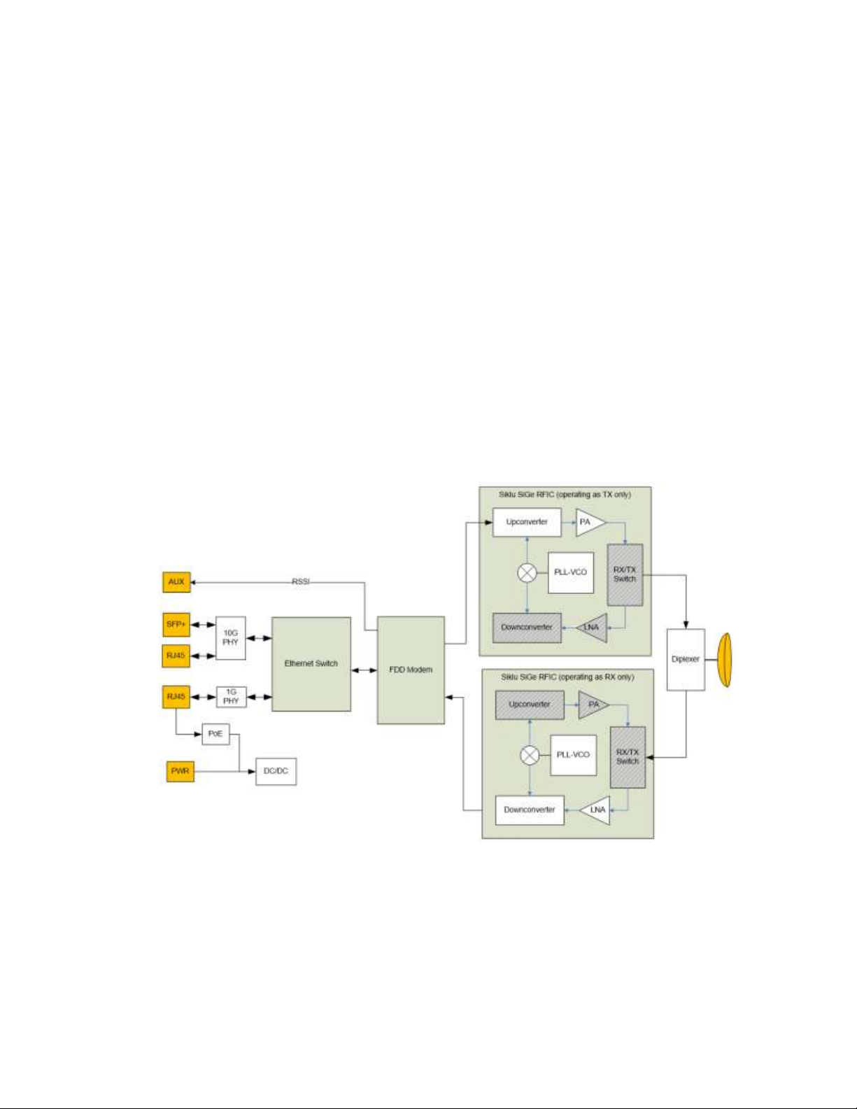
The EtherHaul™ is an all-outdoor system comprised of the following functional blocks:
RFIC: Siklu’s integrated Silicon Germanium (SiGe) transceive r operating at 71-
76/81-86GHz.
Modem/Baseband ASIC: Siklu’s modem/baseband ASIC includes the FDD modem
and FEC engines.
Ethernet Switch: the networking engine is the heart of the high-speed
bridge/router function. The engine receives packets from Ethernet interfaces
and the modem and CPU.
Interfaces: The network interface consists of 1GE and 10GE Ethernet ports,
depending on the product type.
Host processor (CPU) the host processor controls the system responsible for the
control plane, and the antenna alignment.
Antenna: Siklu’s self-designed 0.5ft and 1ft innovative antenna, as well as 2ft
antenna option for longer-range higher availability.
Figure 1-2 EH-8000 Series Functional Block Diagram
Page 17

EtherHaul™ 8000 Installation, Operation and Maintenance Manual
Page 17
2 Installing the Radio Link
This chapter describes how to install and perform the basic setup of a radio link,
including:
Preparing the site
Package content
Unpacking the radio
Required tools
Preparing for installation
Installing the Radio
o With 0.5ft/1ft antenna
o With 2ft antenna
Connecting the cables
System LEDs
Aligning the antenna
Link up verification
The installation of the radio link should be followed by initial system setup that will be
described in the next chapter.
Caution:
The installation and maintenance of the radios should only be done by service
personnel who are properly trained and certified to carry out such activities.
Caution:
It is the responsibility of the installer to insure that when using the outdoor
antenna kits in the United States (or where FCC rules apply) only those
antennas certified with the product are used. The use of any antenna other
than those certified with the product is expressly forbidden in accordance to
FCC rules CFR47 part 15.204.
2.1 Preparing the Site
Carefully select and prepare each radio site to make device installation and
configuration as simple and trouble-free as possible. During site selection and
preparation, always consider the long-term needs of both your network and your
applications.
Page 18

EtherHaul™ 8000 Installation, Operation and Maintenance Manual
Page 18
2.1.1 Physical and Environmental Requirements
Each radio site should adhere to the following requirements:
There must be a clear, unobstructed line-of-sight between radios.
The radio should be mounted on a fixed, stable, permanent structure. A
reinforced steel mounting pole is required, with a diameter measuring from
2-4 inches (0.5ft, 1ft antenna) or 2-4.5 inches (2ft antenna).
Caution:
Do not mount the radio on a structure that is temporary or easily moved. Doing so
may result in poor service or equipment damage.
You must mount the radio in a site that is easily accessible to authorized
personnel, and only authorized personnel.
Operating temperature: between -45° and +55°C.
Relative humidity: 0 to 100%.
Maximum altitude: 4,500m.
Ingress Protection rating: IP67.
2.1.2 Cabling Requirements
Ensure that your power connection cable matches the radio’s power
connector pin-outs.
Install the radio where network connections are ready for operation and
easily accessible.
All cabling connected to the radio should be outdoor-grade, with UV
protection.
You should use shielded outdoor Cat5e cables (for 1GE port) or Cat6 (for
10GE port) terminated with metallic RJ45 connectors.
In order to protect indoor equipment, you must install surge protection
circuits on all copper cables on their entrance to the building.
Install the radio in a location where proper electrical outdoor grounding is
readily available. Typically, the grounding connection is attached directly to
the mounting pole. If not already present, then suitable structure-to-earth
grounding connections must be arranged before installation. Ground the
radio using a minimum quantity of 16AWG grounding cable or according to
local electrical code.
Page 19

EtherHaul™ 8000 Installation, Operation and Maintenance Manual
Page 19
Caution:
Improper electrical grounding can result in excessive electromagnetic interference or
electrical discharge.
This equipment must be permanently earthed for protection and functional
purposes. To make a protective earth connection, use the grounding point located on
the radio using a minimum amount of 16AWG grounding cable or according to local
electrical code.
Siklu will not be held responsible for any malfunction or damage in the event that the
radio is not properly grounded.
2.2 Package Content
A radio link consists of two radios (Outdoor Unit, or ODU), two antennas and two
mounting kits.
The EtherHaul™ packages include the following components:
Package
Description
Quantity
EtherHaul™ ODU
EtherHaul™ ODU with
external antenna interface
1
Connecting cable AllWeather shells
4
Unit grounding cable (90
cm)
1
DC cable terminal block
connector
1
2.3 Unpacking the Radio
The package content should be examined carefully before installation.
When you unpack the components of the radio, it is important to use care so as to avoid
damaging or scratching the antenna radome:
Do not touch the radome when unpacking the antenna.
Do not rest the antenna face down or touch the radome without the
protective cover. It is crucial to prevent contact between the radome and
other objects.
Page 20

EtherHaul™ 8000 Installation, Operation and Maintenance Manual
Page 20
2.4 Required Tools
Ensure that you have the following tools with you when performing the radio link
installation:
Standard handheld digital voltage meter (DVM) with probes
Standard open-end wrench, 13 millimeter (or equivalent Hex socet)
8mm Allen key for ODU installation with 2ft antenna
Standard open-end wrench, 16 millimeter (or equivalent Hex socet)
installation with 2ft antenna
Philips screwdriver, medium size head for grounding connection
Flat head screwdriver, small size (2mm) for DC cable connection
Cable ties (for securing network and optional power cables)
Cutter
2.5 Preparing for Installation
The expected receive signal strength should be calculated prior to installing the link for,
based on the link budget.
Calculating the expected RSSI:
Where:
P
tx
– Radio’s Tx Power (typically +5dBm)
Gant1 – Gain of antenna 1 (typically 35dBi)
Gant2 – Gain of antenna 2 (typically 35dBi)
LFS – Loss of Free Space = 92.45+20*Log (D
Km*FGHz
)+
- D - Link distance in Km
- F – Frequency in GHz
Att
atm
– Attenuation due to Atmospheric Gases (dB/Km)
For E-band links, the Attenuation due to Atmospheric Gases is typically
0.5dB/Km.
Refer to the online Link Budget Calculator on www.siklu.com for on-line
calculation of expected availability and expected RSSI.
RSSI = Ptx + G
ant1
– LFS – Att
atm
+ Gant2
Page 21
EtherHaul™ 8000 Installation, Operation and Maintenance Manual
Page 21
2.6 Installing the Radio with a 0.5ft/1ft Antenna
2.6.1 Attaching the Antenna to the Radio
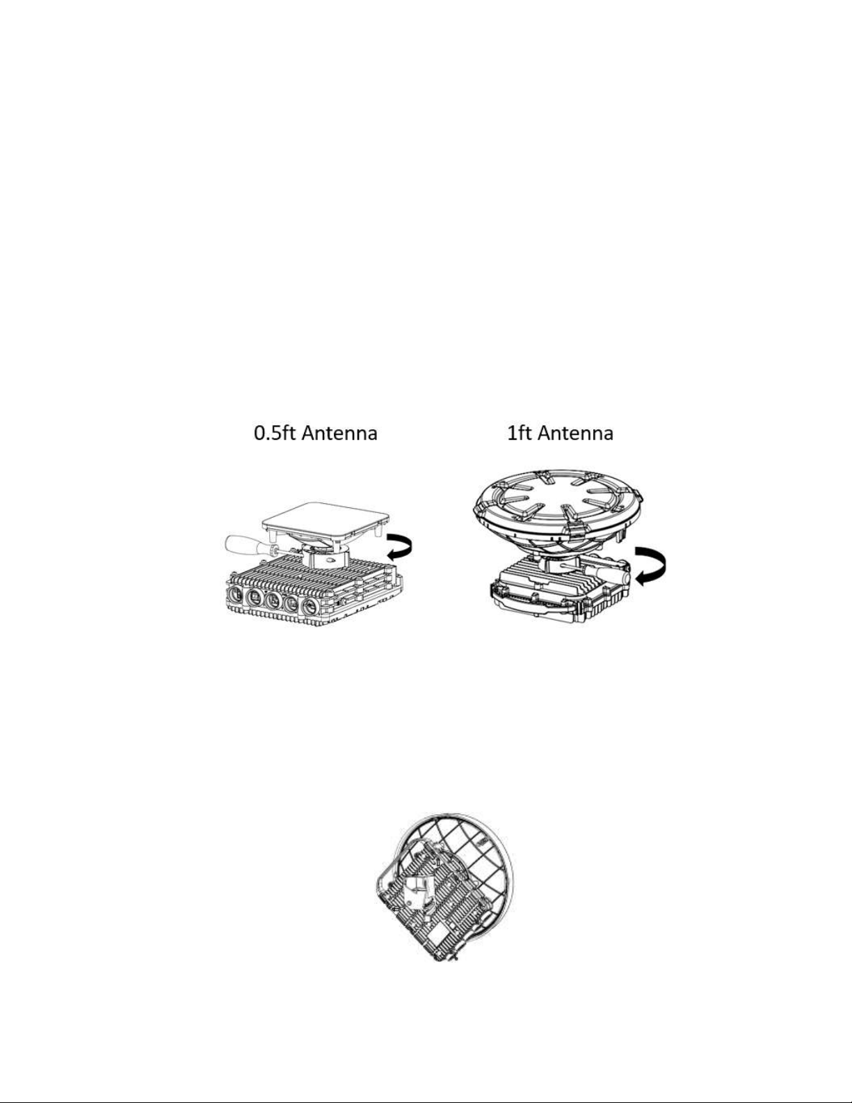
1. Unpack the radio, place it on a clean unobstructed work surface area, and
remove the plastic cap protecting the waveguide interface.
2. Unpack the antenna, keeping the plastic protective cover in place, and remove
the plastic cap protecting the antenna feed.
3. Place the antenna on top of the radio while aligning the guiding pin on the
antenna to the guiding hole on the radio.
4. Gently rotate the antenna until you notice the guiding pin is in place.
5. Turn the locking ring clockwise, securing the antenna to the radio.
6. Use medium-size screwdriver to tighten the locking ring is place.
Figure 2-1 Attaching the Antenna to the Radio (0.5ft and 1ft Antennas)
7. Flip the radio, placing it on the antenna plastic protecting cover.
8. Use a 7mm Hex screwdriver to attach the Quick Release Plate to the back of the
radio using 4x 7mm screws.
9. The arrow on the Quick Release Plate should point to “V” on the back of the
radio, indicating vertical polarization. You may choose Horizontal polarization if
required.
Figure 2-2 Attaching the Quick Release Plate andSetting Polarization
Page 22
EtherHaul™ 8000 Installation, Operation and Maintenance Manual
Page 22
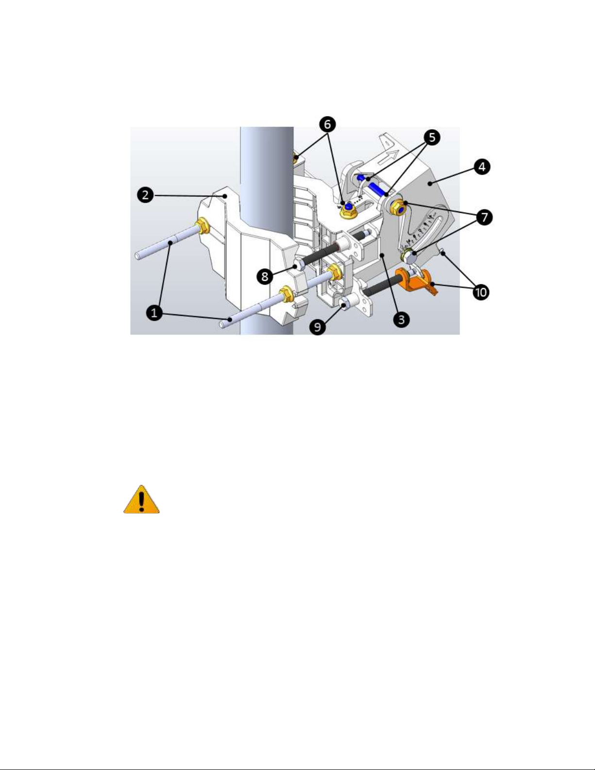
2.6.2 Mounting using 1ft Mounting Kit
1. Unit mounting screws and bolts
6. Azimuth adjustment lock bolts
2. Back mounting bracket
7. Elevation adjustment lock bolts
3. Front mounting bracket
8. Azimuth fine adjustment screw (± 8)
4. Quick release plate (attached to radio)
9. Elevation fine adjustment screw (± 16 )
5. Quick release hooks
10. Elevation screw tension band and pin
Figure 2-3 1ft Mounting Kit Components
Note:
Torque level for tightening all nuts and bolts is 8nm.
1. Prior to mounting, unpack the mounting kit package and attach the two unit
mounting screws () to the front mounting bracket (), securing them with
mounting bolts.
2. Assemble the back () mounting bracket to the front () mounting bracket
using one bolt and separate them by about 120 degrees so that the assembly
can to be attached to the mounting pole.
3. Place the assembly on the mounting pole and rotate the front and back
mounting brackets to fit the assembly on the pole. Add the unit mounting bolt
that was removed.
4. Ensure that both front and back mounting brackets are attached evenly to the
pole, and are completely level.
Page 23
EtherHaul™ 8000 Installation, Operation and Maintenance Manual
Page 23
5. Use the 13mm open wrench to tighten the nuts on both unit mounting bolts.
Temporarily tighten the unit mounting bolts at this stage to keep the unit from
moving freely.
6. Verify that quick release plate () is attached according to the desired
polarization. If necessary, change the radio polarization to match the orientation
of the remote radio by removing the quick release plate, changing its
orientation, and reattaching. For ease of reference, the markings V (vertical) and
H (horizontal) are engraved on the back side of the radio.
7. Examine the position scales of both the Azimuth adjustment lock bolts () and
the elevation adjustment lock bolts (), found on the front mounting bracket,
and ensure that they are positioned at 0 degrees (in the middle of the scale).
8. Position the quick release hooks () onto the top elevation adjustment lock bolt
() and carefully set the radio in place on the front mounting bracket and slide
it firmly inwards.
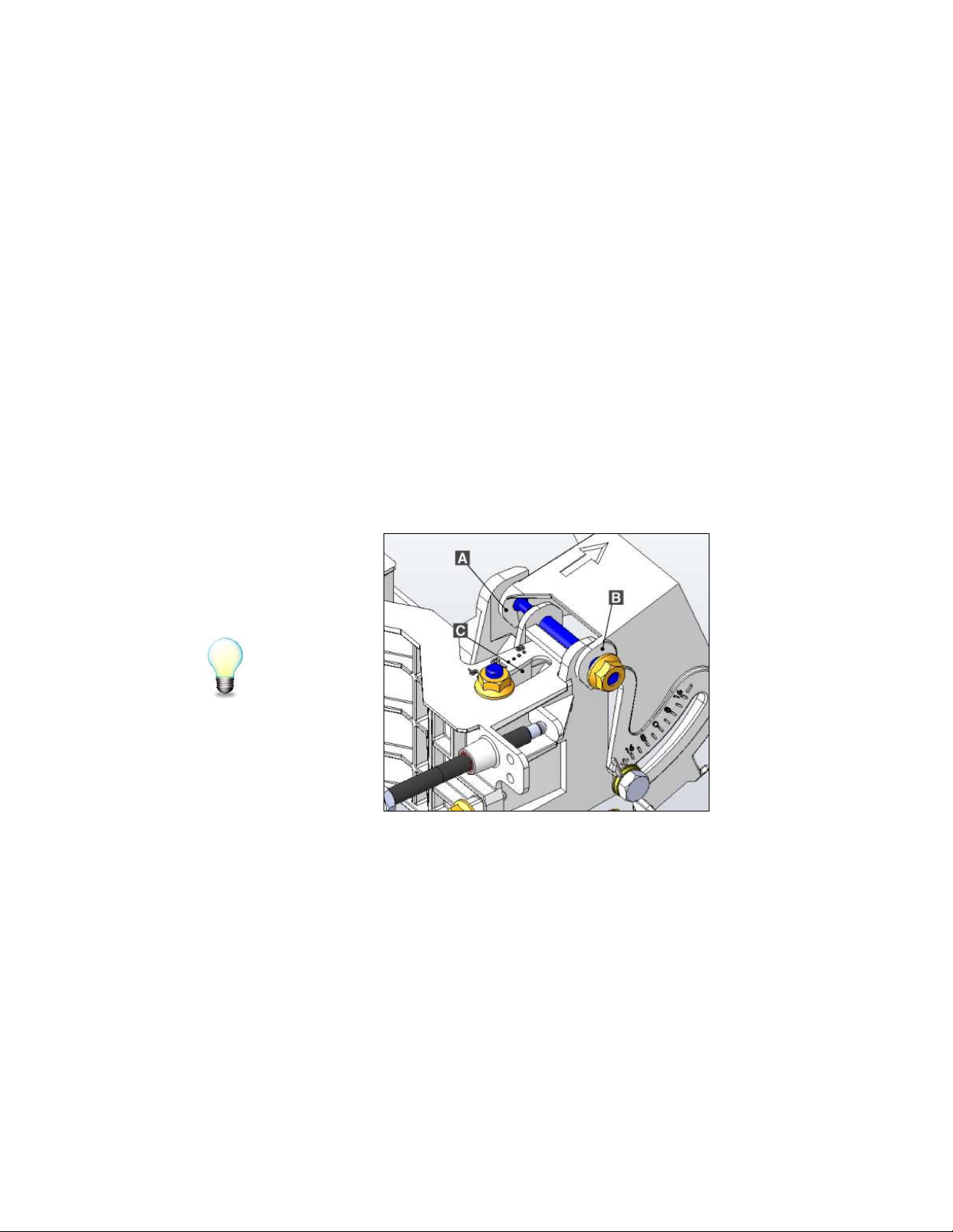
Hint:
Mount the radio by attaching the interior quick release hook (A) in place before
attaching the exterior hook (B). The interior hook is the one located farthest from the
tightening nut, as shown below.
A. Interior Quick Release Hook
B. Exterior Quick Release Hook
C. Elevation Position Slot
Figure 2-4 Quick Release Hooks
9. Unlock the Azimuth adjustment lock bolts () and the elevation adjustment lock
bolts ().
10. Stretch the elevation screw tension band () slightly and connect it to its
mating tension pin, located on the quick release plate.
Page 24
EtherHaul™ 8000 Installation, Operation and Maintenance Manual
Page 24
2.7 Installing the Radio with a 2ft Antenna
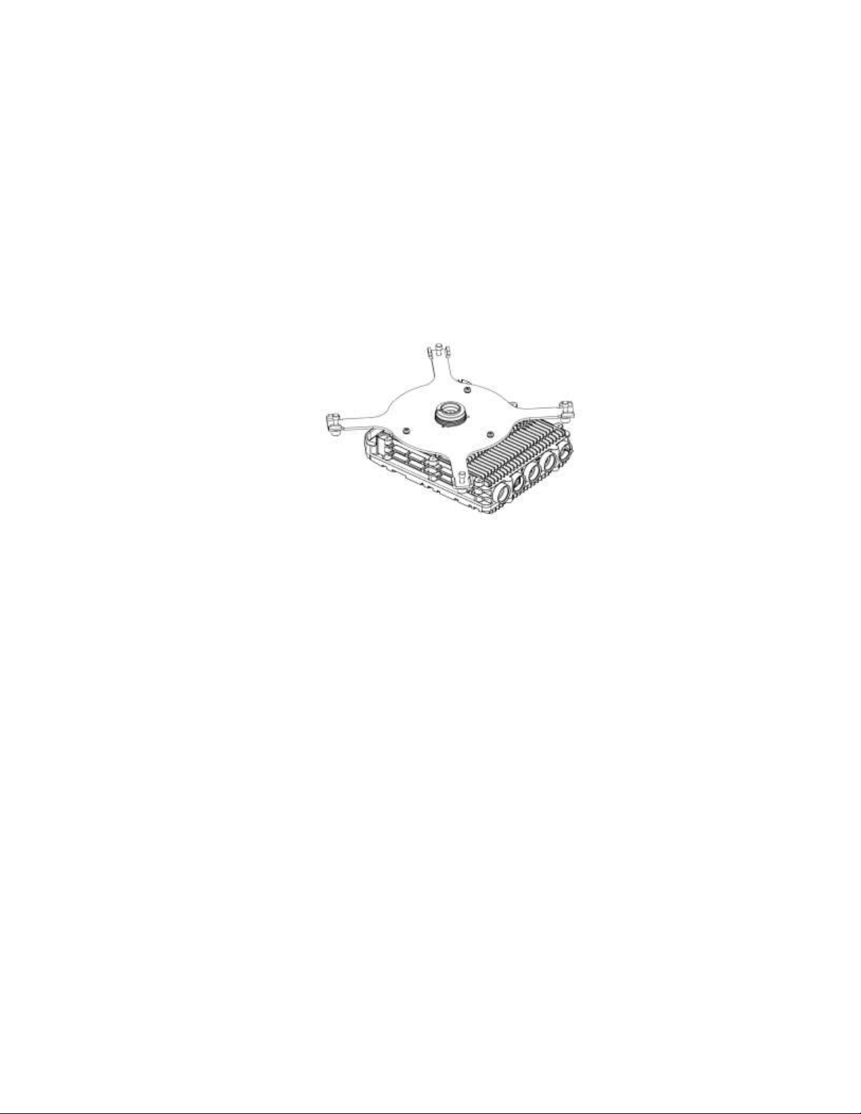
2.7.1 Attaching the 2ft Adapter to the Radio
1. Unpack the radio, place it on a clean unobstructed work surface area, and
remove the plastic cap protecting the waveguide interface.
2. Unpack the cross-shaped metal adapter plate (shipped with each 2ft antenna)
and attach it to the radio using the supplied Phillips-head screws.
3. Note that the you should use only the 3 longer screws that should go on the
outer perimeter. No need for the 3 shorter ones (relevant for other radio
models).
Figure 2-5 2ft Adapter
2.7.2 Attaching the Radio to the 2ft Antenna
1. Unpack the antenna and place it on a clean unobstructed work surface area in
its protective housing.
2. Use care to avoid damaging or scratching the antenna radome.
3. Remove the protective tape on the antenna feed.
4. Unpack the antenna mounting kit and assemble it according to the antenna
mounting kit installation instructions that can be found in the antenna package.
5. Position the Azimuth and Elevation Adjustment Lock Bolts at 0 degrees (in the
middle of the scale) and unlock them to allow free movement during alignment.
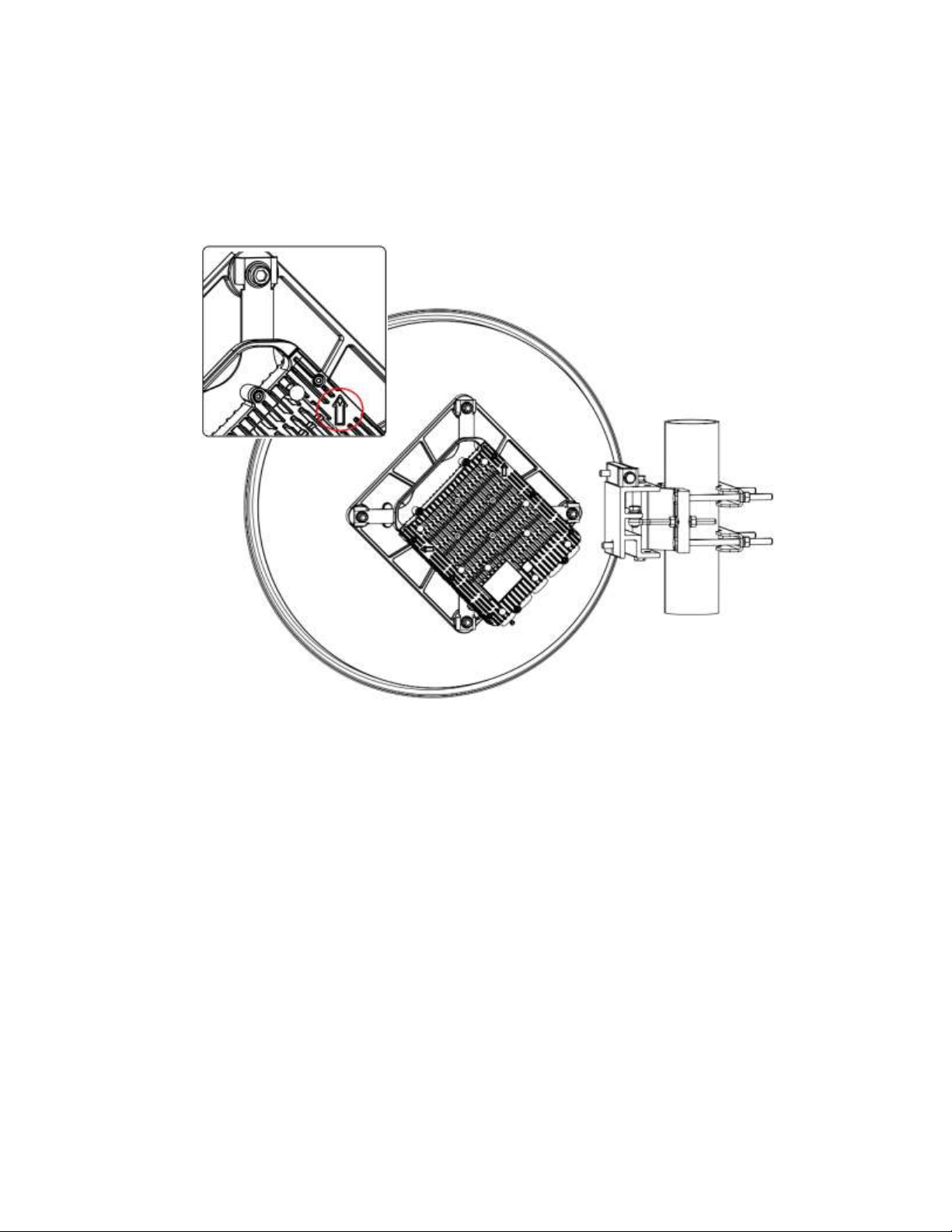
6. Attach the radio to the antenna and tight the 4 locking bolts using 8mm Allen
key.
7. Make sure you install the radio on the required polarization (note the
polarization arrow on the back of the radio).
8. Note that 2ft antenna can be installed either with right or left offset from the
pole.
Page 25
EtherHaul™ 8000 Installation, Operation and Maintenance Manual
Page 25
9. Mount the antenna on a fixed reinforced steel mounting pole with 2-4.5 inches
diameter.
10. Install the 2ft antenna according to the antenna installation instructions that can
be found on the antenna/mounting kit package.
Figure 2-6 Radio Installed on a 2ft Antenna
11. Pluck the plastic plug at the very bottom of the antenna (drain hole).
Page 26
EtherHaul™ 8000 Installation, Operation and Maintenance Manual
Page 26
2.8 Connecting the Cables
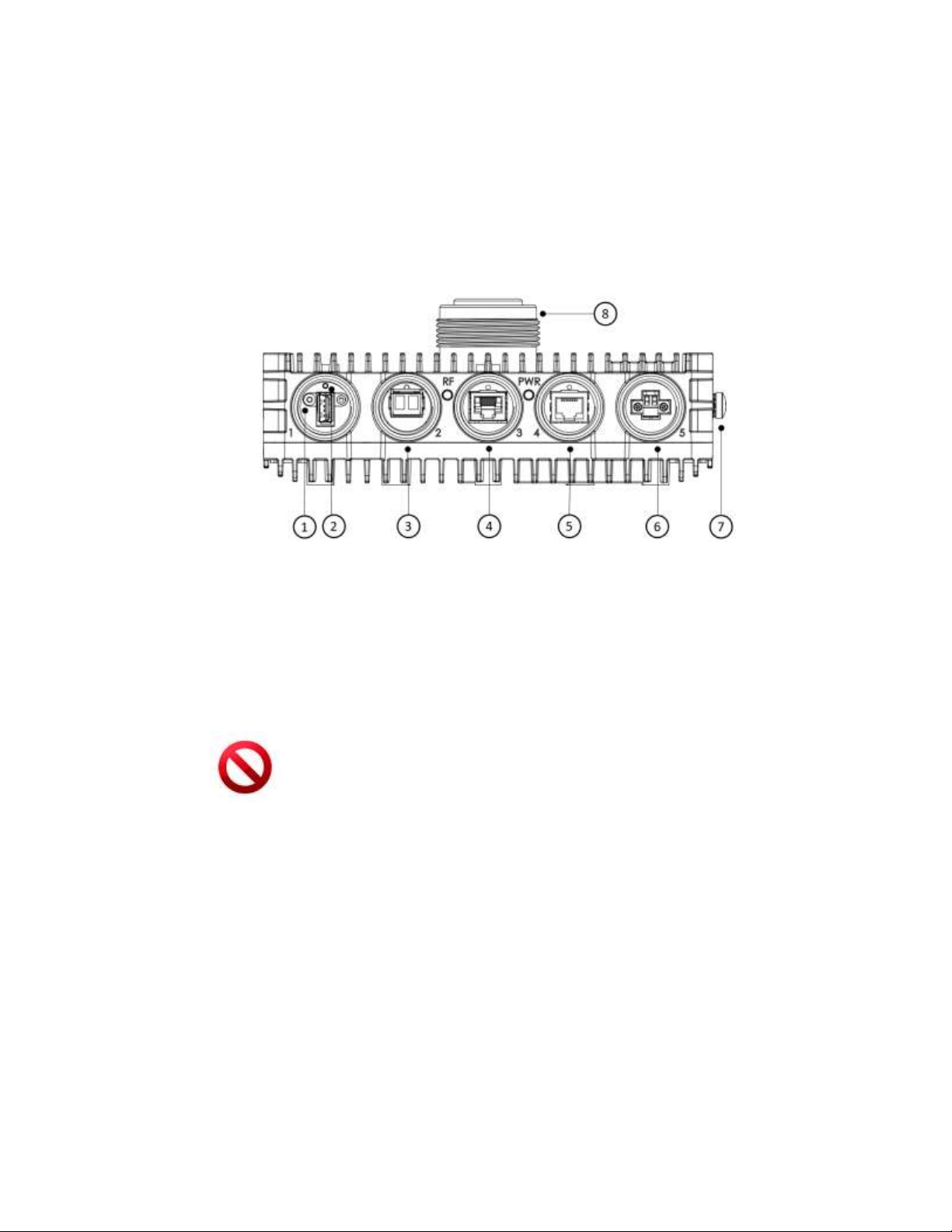
The following figure shows the radio interfaces. There are three line interfaces
available:
1GE: 802.3ab (RJ45, Cat5e or better cable), for PoE In and as 1G line interface
10GE combo port: 802.3an/bz (RJ45, Cat6a or better cable) or SFP+ (SMF or
MMF)
1. DVM Probe Interface (AUX)
5. Ethernet port #1 RJ45 (PoE In)
2. Reboot button (press for 10 seconds for factory settings reset)
6. DC In
3. Ethernet 10G SFP+
7. Electrical Ground (GND)
4. Ethernet 10G 802.3an RJ45
8. Antenna Interface
Figure 2-7 Front Panel Details
Caution:
Use only Class 1 Laser SFP which is safety approved to IEC 60825 and which is
CDRH registered
2.8.1 Power Supply Notes
2.8.1.1 DC Power
The DC power input range of the radio is 42 - 57 VDC.
The DC supply should be limited to 2A to avoid surges and possible damage to
the radio. For that, use limited power supply or circuit breaker (fast-blow fuse).
The circuit breaker is the disconnecting device, and should be readily accessible.
Page 27
EtherHaul™ 8000 Installation, Operation and Maintenance Manual
Page 27
When connecting the radio to a MAINS DC distribution system, use a 2A circuit
breaker to enable the central DC system to isolate the radio in an emergency
case.
Use one poly circuit breaker and should connect it on the live voltage: (+) or ( -).
The other poly should be grounded.
Connect the circuit breaker to the (+) or (-) live voltage.
The DC input is floating, so either (+) or (-) can be connected to the GND on the
power supply side. For the sake of consistency with other systems, we
recommend that you connect the (+) to the GND.
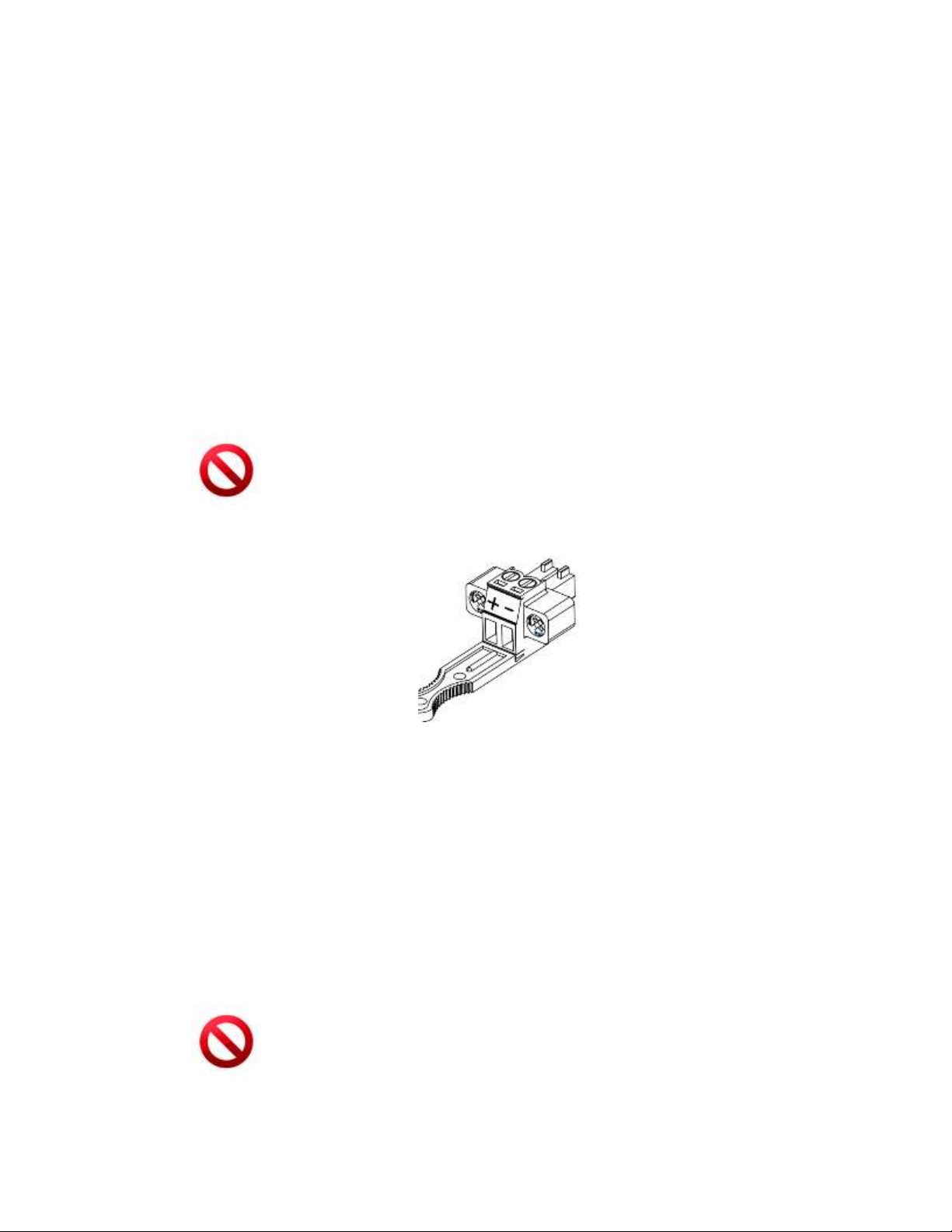
Use a two-wire cable (14-18 AWG) to connect the power supply to the radio. On
the radio DC terminal, connect the (+) and (-) wires to the correct ports.
Caution:
Use DC power supply which is safety approved to UL/EN/IEC 60950-1 with rated
voltage of 42-57 VDC and rated current of 2A max
Figure 2-8 DC Terminal Block
Use screwdriver to tight and lock the connector’s locking bolts.
2.8.1.2 PoE Power
Connect Power over Ethernet (PoE) to port Eth1 only.
The PoE power range of the unit is 42-57V.
The power source should be limited to 1.4A to avoid surges and possible damage
to the radio.
Caution:
Use a PoE power supply which is safety approved to UL/EN/IEC 60950-1 as a limited
power source (LPS) with rated voltage of 42-57 VDC and rated current of 1.4A max
Page 28

EtherHaul™ 8000 Installation, Operation and Maintenance Manual
Page 28
Caution:
This system may have more than one power supply cable. To reduce the risk of
electrical shock, a trained service technician may need to disconnect all power supply
cables before servicing the system.
2.8.2 Grounding the Radio
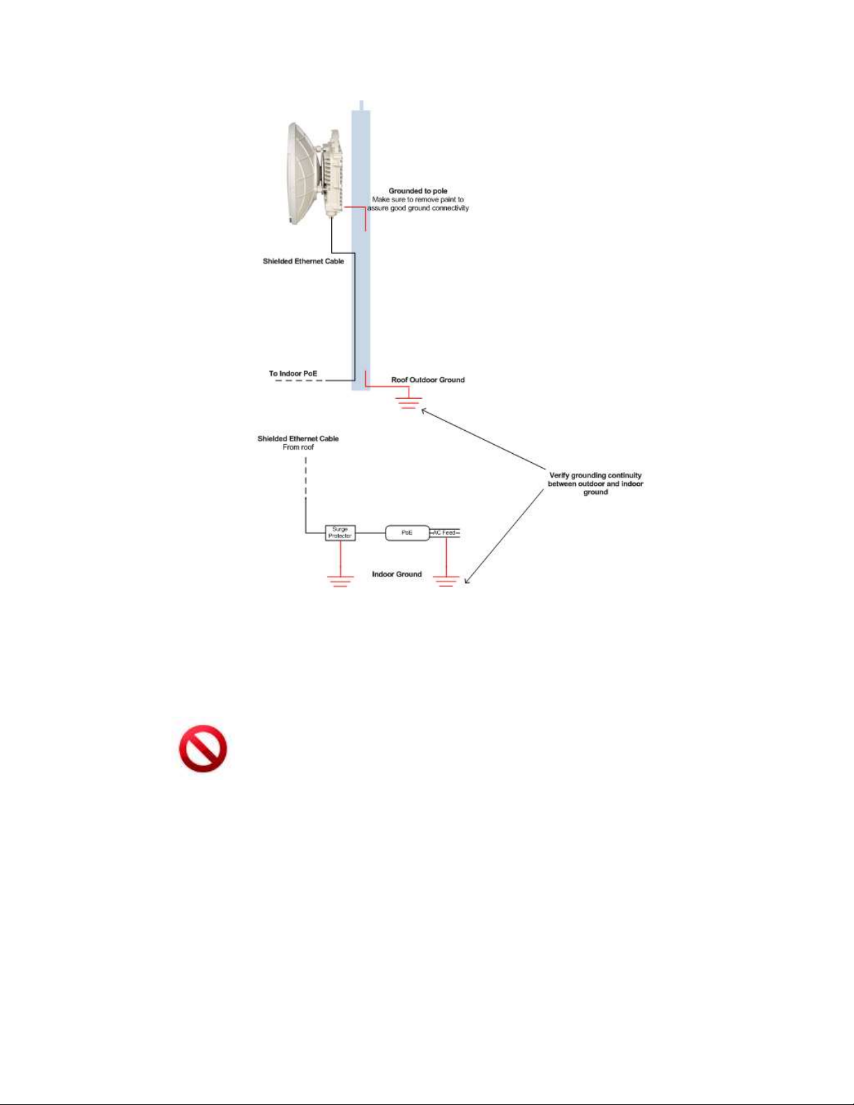
1. Connect one end of the grounding cable to the ground outlet on the left side of
the radio using the grounding cable lug.
2. Tighten the lug securely in place.
3. Connect the opposite end of the grounding cable to the earth connection,
typically located on the mounting pole. If the earth connection is out of reach of
the grounding cable, install an alternative cable.
To make a protective earth connection, use the grounding point located on the System
radio using a minimum amount of 16AWG grounding cable or according to local
electrical code.
It is recommended to use Lightning Surge Protector on every Ethernet cable to protect
the indoor networking equipment. The Lightning Surge Arrestor should be installed
indoor next to the cable’s point-of-entry and should be properly grounded.
Page 29
EtherHaul™ 8000 Installation, Operation and Maintenance Manual
Page 29
Figure 2-9 Grounding Scheme
Caution:
Improper electrical grounding can result in excessive electromagnetic interference or
electrical discharge.
This equipment must be permanently earthed for protection and functional
purposes. To make a protective earth connection, use the grounding point located on
the radio using a minimum amount of 16AWG grounding cable or according to local
electrical code.
Siklu will not be held responsible for any malfunction or damage in the event that the
radio is not properly grounded.
2.8.3 Preparing the Cables
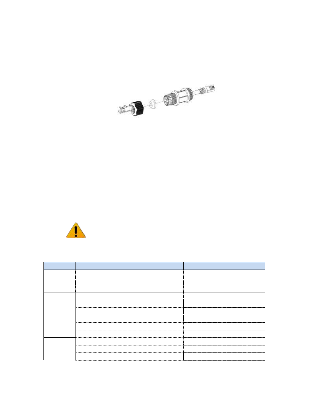
Before inserting the cable connector into the radio, you must first enclose the cable
connector in a protective All-Weather shell. Three sets of All-Weather shells are
provided with the radio for the radio interfaces.
The provided protective All-Weather Shells fit cables from 3.5mm to 9.0mm diameter.
Page 30
EtherHaul™ 8000 Installation, Operation and Maintenance Manual
Page 30
1. Thread the cable and tight the shell to the radio firmly by hand (do not use
tools).
2. Insert the rubber gasket snugly and tight the connector lock
3. When removing the All-Weather Shell, unlock the gland first before removing
the shell.
Figure 2-10 All-Weather Connecting Cable Shell Assembly
2.8.4 Powering up the Radio
1. Connect power cable (DC or PoE)
2. Insert the power connector into the port. The PWR LED color indicator turn s red
for one second, then blinks green indicating that the radio is powered on.
3. Wait for the radio to boot up (about 90 seconds). When the radio is fully
booted, the PWR LED color indicator turns green (during power-up the PWR LED
blinks green) and the RF LED color indicator turns off, indicating that the link is
down.
Note:
The radio supports power backup – connecting both PoE and DC feed (for hotstandby resiliency). In case both feeds are available, the radio will use the power
source with higher voltage.
2.9 System LEDs
LED
Color
Description
PWR (Power)
Green – Power OK
Blink Green – Device boot (~90 sec)
Red – Power Failure
Off – Radio off
RF
Green – Link Up
Orange – Alignment Mode
Off – Link Down
1G port:
Green – Link (Carrier) 1G
Blink Green – 1G activity
Orange – Link (Carrier) 10/100M
Blink Orange – 10/100M activity
Off – No Link (Carrier)
10G ports:
Green – Link (Carrier) 10G
Blink Green – 10G activity
Orange – Link (Carrier) 10/100/1G/2.5G/5G (RJ45 only)
Blink Orange – 10/100/1G/2.5G/5G activity
Off – No Link (Carrier)
Page 31

EtherHaul™ 8000 Installation, Operation and Maintenance Manual
Page 31
2.10 Aligning the Antenna
For optimal radio link performance, antennas must be accurately aligned. In order to
align the antennas, perform first coarse alignment of each antenna, followed by fine
alignment. Accurate alignment of the antennas is critical for achieving the strongest
possible receive signal.
To perform antenna alignment, the radio must be in Alignment mode.
The radio has three modes of operation:
Alignment – Carrier Wave transmission. Used for antenna alignment.
Adaptive – Operational mode used with adaptive bandwidth, code, and
modulation.
Static – Operational mode used with a fixed modulation profile.
Radios are shipped from the factory in Adaptive mode.
2.10.1 Switching the Radio to Alignment Mode
Switch the radios to Alignment mode by inserting the DVM probes into the AUX
Interface sockets. The RF LED color indicator turns orange, indicating the radio is in
Alignment mode.
The radio remains in Alignment mode even if the DVM probes are ejected, until the
radio is rebooted.
You can also switch the radio to and from alignment mode using management
commands (web GUI or CLI).
2.10.2 Performing the Alignment
Note:
The following instructions detail the alignment steps of 0.5/1ft antenna and refer to
Figure 2-3 1ft Mounting Kit Components.
1. Verify that the radio is in Alignment Mode.
Coarse Alignment (Azimuth Only)
2. Loosen the unit mounting bolts () slightly to allow the radio some freedom of
movement.
3. Perform coarse alignment using a line-of-sight visual check with the remote
radio. Lock the unit mounting bolts () using the 13mm open wrench.
4. Repeat steps 0 to 3 above on the remote radio.
Page 32
EtherHaul™ 8000 Installation, Operation and Maintenance Manual
Page 32
Note:
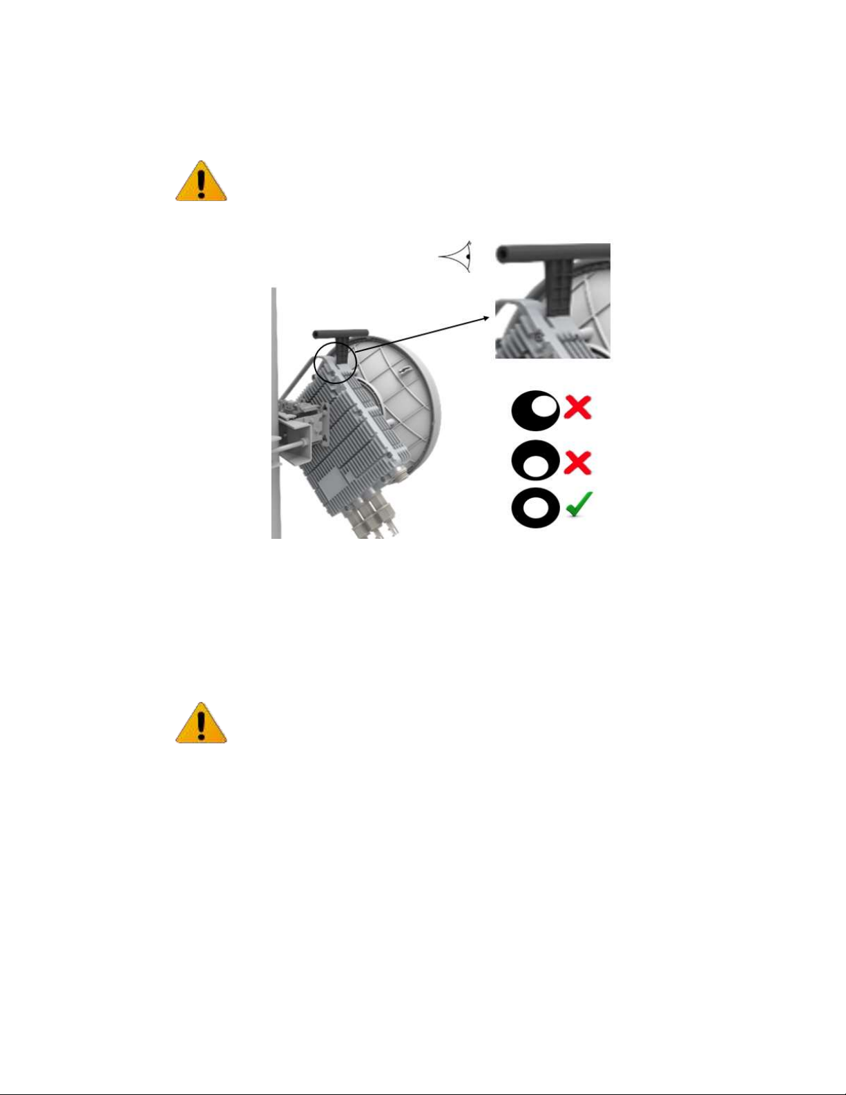
You can use the visual alignment tool that can be found in the 1ft antenna box for
coarse alignment. Attach it to the antenna and align the antenna untill the remote
antenna can be seen in the center of the eyepiece.
Figure 2-11 1ft Antenna Visual Alignment Tool
Fine Alignment
Note:
When aligning an antenna, the antenna in the remote node must remain stationary.
Perform Fine alignment first on the local antenna, and only afterwards on the remote
antenna.
The optimum alignment may require several adjustment iterations between the local
and remote antennas.
5. Connect the DVM to the radio by inserting both red and black probes into their
appropriate positions in the AUX port.
Throughout the alignment procedure, you must compare the actual receive
signal strength indication (RSSI) to the expected RSSI that was calculated during
network link budget preparation (refer to Preparing for Installation on page 20).
Read the receive level (RSSI) using the DVM. The voltage reading will be
between 0 to 1V, indicating the RSSI in dBms. For example, a DVM reading of
0.45V is equivalent to -45 dBm.
Page 33

EtherHaul™ 8000 Installation, Operation and Maintenance Manual
Page 33
6. Align the fine Azimuth axis. Use the hexagonal wrench to adjust the Azimuth fine
adjustment screw (). Be sure to sweep the complete range of the Azimuth in
order to determine the maximum received signal strength position.
When the optimum axis is achieved, tighten both Azimuth adjustment lock bolts
().
7. Align the fine elevation axis. Use the hexagonal wrench to adjust the elevation
fine adjustment screw (). Be sure to sweep the complete range of the
elevation in order to determine the maximum received signal strength position.
When the optimum axis is achieved, tighten both elevation adjustment lock
bolts ().
8. Perform steps 6 and 7 for the remote radio.
9. Repeat steps 6 and 7 for the local radio and so on until optimum achieved.
10. Use the DVM to verify maximum received signal strength on both local and
remote radios. For best performance, measured RSSI should be within ±4 dB of
the calculated value.
11. Once the optimum position has been achieved for the link, tighten the Azimuth
adjustment lock bolts () on one radio (torque of 8 Nm), being very careful not
to move the radio while tightening.
12. Tightening the Azimuth adjustment lock bolts will tilt the radio, so realign the
elevation again for optimum position.
13. Once the optimum position has been achieved for the radio pair, tighten the
elevation adjustment lock bolts () on the radio (torque of 8 Nm), being very
careful not to move the radio when tightening.
14. Repeat steps 11 through 13 for the second radio.
15. Use the DVM to verify that the received signal strength has not changed on
either the local or the remote radio after final tightening of the brackets.
Antenna alignment is now complete.
Note:
Valid RSSI reading during alignment is available up to an RSSI value of -30dBm
(overload threshold). When operating short links (or using large antennas to achieve
high availability) resulting in expected RSSI higher than -30dBm, RSSI reading may not
be accurate due to saturation.
In such case, it is recommended to connect to the radio and switch both sides to
Short Range. Short Range mode allows the radio to work with higher RSSI levels (up
to about -25dBm), compared to the typical overload threshold of -30dBm.
In case expected RSSI is higher than -25dBm, adjust the Tx power until RSSI is -25dBm
and only then align the antennas.
Page 34

EtherHaul™ 8000 Installation, Operation and Maintenance Manual
Page 34
2.11 Link Up Verification
1. Disconnect the DVM probes.
2. Reboot both radios by shortly pressing the Reset Button or alternatively
disconnect/reconnect the power.
3. This action will switch the radios back to Adaptive Mode (radio’s default
operational mode). Following this action, and after the radio has finished
booting, the RF LED color indicator on both radios will turn Green, indicating
that the radio link is up.
The radio link can now pass traffic between ports and over the radio link.
Page 35

EtherHaul™ 8000 Installation, Operation and Maintenance Manual
Page 35
3 Setup and Monitoring Using the Web-based
Management
In order to carry configuration, monitoring or maintenance tasks, connect your station
to the system’s 1G Ethernet port and launch the chosen management option.
There are two options to connect and manage the radio:
1) Embedded HTML Web-Based Management.
The recommended management option. The use of this option is described in details
in this document. It provides self-explanatory graphical user interface for managing
both ends of the link.
2) Command Line Interface (CLI).
Provides command line interface for configuration and monitoring. Includes the entire
configuration options of the system.
General format of CLI command:
command object <object-id(s)> [attribute-name <attribute-value>]
for example:
set eth eth1 eth-type 1000FD
show bridge all all statistics
Typical commands:
Set, show, clear, reset, run, copy
General CLI conventions:
o Confirmation after each command correctly entered.
o Error-message with hint in case of wrong command.
o Use Tab for Auto-complete.
o Use Up Arrow and Down Arrow to display command history.
o Use ? for help on possible configuration options and for exact command
syntax.
This chapter includes the following topics:
Connecting to system using the Web-Based Management.
Connecting to system using the Command Line Interface.
Web-Based Management Main Page.
Quick Configuration Wizard.
General Configuration Commands.
Page 36
EtherHaul™ 8000 Installation, Operation and Maintenance Manual
Page 36
3.1 Connecting to the Radio Using the Web-Based Management
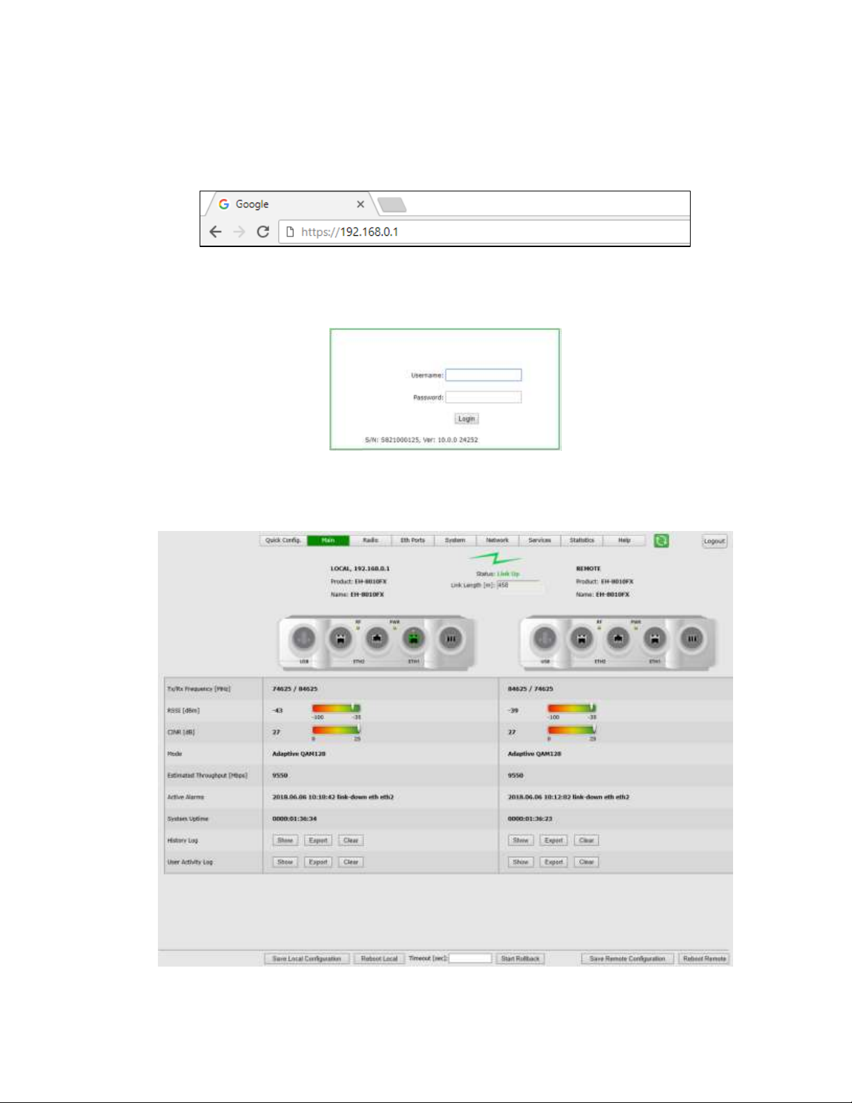
1. Launch an Internet Browser and enter https:// followed by the system’s IP
address. The system’s default IP address is 192.168.0.1.
Figure 3-1 Launching the Web-Based Management
2. When prompted, enter the username and password. Default: admin and admin.
Figure 3-2 Entering Username and Password
3. Once loaded, the Web-Based Management Main page is displayed.
Figure 3-3 Web-Based Management Main Page
Page 37
EtherHaul™ 8000 Installation, Operation and Maintenance Manual
Page 37
3.2 Connecting to the Radio Using the Command Line Interface
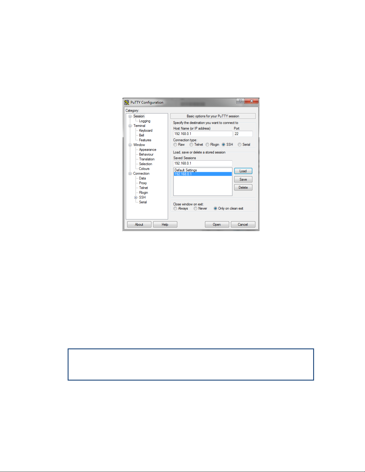
1. Launch standard SSH client. You can use any common, open source SSH client
program, such as PuTTY, available for download from the web.
Open an SSH session to the system’s IP address. The system’s default IP address
is 192.168.0.1.
Figure 3-4 Launching CLI
2. PuTTY configuration (Recommended):
a. Go to category: Terminal -> Keyboard
Set Backspace key = Control-H
Set The function keys and keypad = Linux
b. Go to category: Window
Set Lines of Scrollback = 100000
c. Save the session and configuration. Give it a name and Click Save. The session
will be stored under the Saved Sessions.
4. When prompted, enter the username and password. Default: admin and admin.
login as: admin
EH-8010FX, S/N: F813036112, Ver: 8.0.0 21309
Password:
EH-8010FX>
Page 38

EtherHaul™ 8000 Installation, Operation and Maintenance Manual
Page 38
3.3 Web-Based Management Main Page
The Web-Based Management provides link view, presenting both local and remote
configuration and monitoring.
Although the local and remote systems IP address is identical (default IP address
192.168.0.1), the remote will be available as well as the radio uses dedicated
communication channel for local-remote communication that is not IP-based.
It is recommended, however, to assign dedicated IP address for local and remote
systems.
Note:
Depending on your station’s screen size and resolution, you may need to scroll the
screen vertically or horizontally in order to view all options for local + remote.
Alternatively, you may change the change the Internet’s Browser display distance
(Zoom out, using Ctrl+Minus).
The Web-Based Management Main page is a read-only page and displays the following
information:
Link Status – Link up or down (with visual indication)
Link Length [m] – link calculated distance between the local and remote systems
(air distance) based on propagation time.
Tx/Rx frequency [MHz].
RSSI [dBm] – Receiver Signal Strength Indicator. Current receive level.
CINR [dB] – Carrier to Interference + Noise ratio. Indicates the current radio
link’s signal quality. In normal conditions, CINR≥19 indicates a good signal
quality.
Mode – Current operational mode of the link:
o Alignment – Carrier Wave transmission. Used for antenna alignment. No
data over the radio link.
o Static – Fixed modulation profile. If you select Static, you must select from a
list of pre–configured modulation profiles in the Modulation field.
o Adaptive – Adaptive Bandwidth, Code, and Modulation. The system will
work on the highest modulation profile based on the CINR values of the both
sides and will present the current modulation profile.
Estimated Throughput [Mbps] – based on the current modulation profile and
capacitylicense (value is Full-Duplex).
Page 39

EtherHaul™ 8000 Installation, Operation and Maintenance Manual
Page 39
Active Alarms – list of currently active alarms and date&time raised.
System Uptime – R/O field. Time elapsed from last power on.
History Log – System alarms and events history log.
User Activity Log – All configuration changes are logged, including user and
date&time (presented in the form of CLI commands).
3.4 Quick Configuration Wizard
Use the Quick Configuration wizard to configure the basic system parameters for both
local and remote systems. It holds the basic minimal configuration required to start
using the link.
The Quick Configuration wizard should be used for the initial system setup after
installation. For monitoring and advanced configuration, please refer to the dedicated
configuration pages of the Web-Based Management.
3.5 General Configuration Commands
3.5.1 Apply
Any configuration change is executed upon clicking Apply.
The Local-Remote concept of the Web-Based Management allows configuring both local
and remote systems of the link.
The Apply button is available at the bottom of each configuration page (one button for
both local and remote systems).
When clicking Apply, the configuration changes will be sent to remote system first and
then to the local system. If multiple parameters changed on the page before clicking
Note:
Actual Layer 1 throughput depends on product's specs. Refer to the product’s
Release Notes for exact specifications.
Note:
To view logs, pop-ups must be enabled and allowed on your Internet Browser.
Page 40

EtherHaul™ 8000 Installation, Operation and Maintenance Manual
Page 40
Apply, all parameters are sent in bulk to the system and then executed locally in order
to avoid losing management connection.
3.5.2 Save Configuration
Any configuration change applied should be saved using the Save Configuration
button.
The system has two configuration banks:
1. Running Configuration – the currently active configuration. Every time Apply is
clicked, the Running Configuration is updated.
2. Startup Configuration – the configuration the system will come up with after the
next reboot. This configuration may be different than the currently active
configuration (Running Configuration).
In order to save the applied configuration changes, click Save Configuration so
changes will be saved to the startup configuration. If changes are not saved to the
startup configuration, they will be lost the next time the system reboots.
Save Configuration buttons are available for local and remote systems.
A Save icon is displayed on the all Web-Management pages, as a reminder, in case
configuration changes were made and not saved.
3.5.3 Rollback
A safety measure that allows recovering from system configuration changes that caused
loss of communication.
When Rollback is used, a timer runs (and restarts) whenever a management (or CLI)
command is entered. In the event that no command is entered within the timeout
period, the system automatically reboots and comes up with the saved startup
configuration.
A Rollback timeout is especially recommended when configuring remote elements that
are being managed over the link.
Rollback is activated for both local and remote systems.
3.5.4 Reboot
Separate buttons for local and remote reboot. The system will power off and then on
and come up after initialization (~90 seconds).
Note that any unsaved changes will be lost.
Page 41

EtherHaul™ 8000 Installation, Operation and Maintenance Manual
Page 41
3.6 Copy To Remote
You can find the Copy To Remote button next to some configuration parameters or
sections. This function copies configuration to remote system based on the changes on
the local system.
Figure 3-5 Copy To-Remote icon
Matching configuration may be of two types:
Identical configuration – exactly same configuration will be copied from the
local to remote system. It can be found for parameters that normally
requires identical configuration for both local and remote units.
For example, Mode configuration.
Matching configuration – for parameters that require matching but
opposite configuration.
For example: transmit frequency where Tx(local)=Rx(remote) and
Rx(local)=Tx(remote).
Page 42
EtherHaul™ 8000 Installation, Operation and Maintenance Manual
Page 42
4 Radio Configuration and Monitoring
The radio link parameters and radio link monitoring are managed in the Radio page.
This chapter includes the following topics:
Settings
Advanced Settings
Maintenance
Modulation Table
Statistics
CLI commands
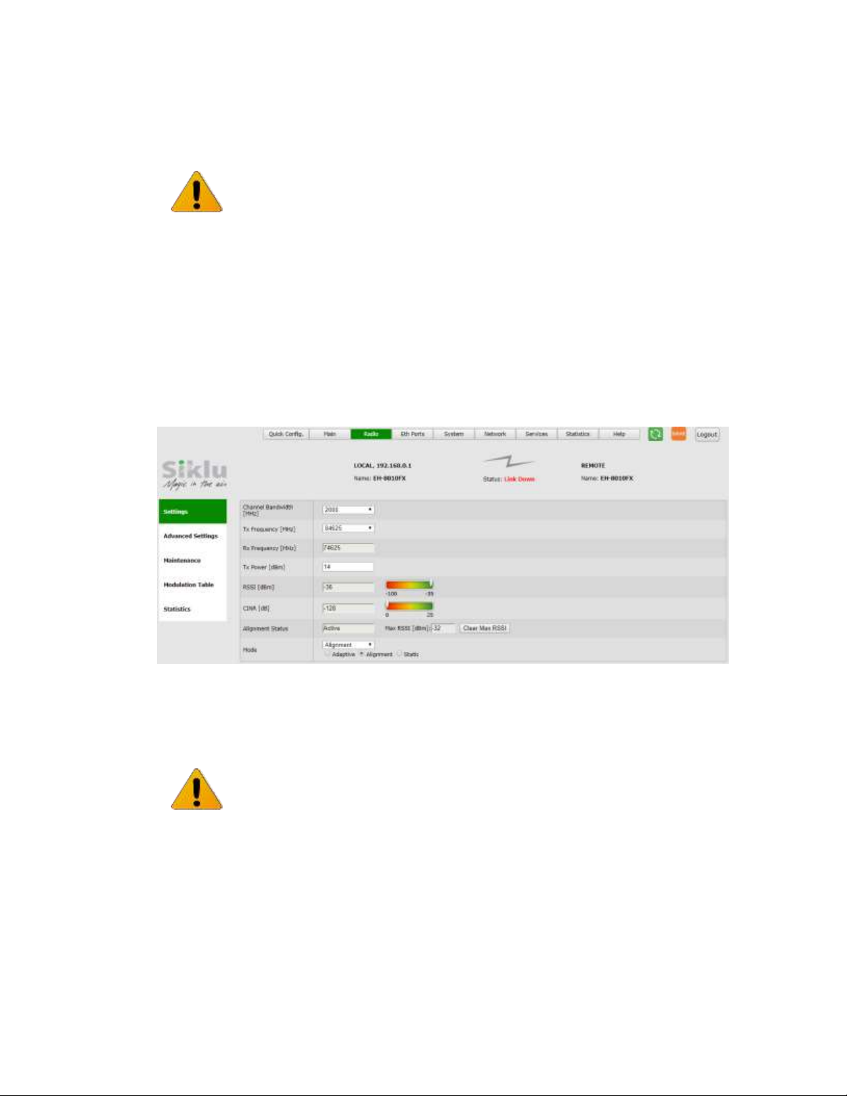
4.1 Settings
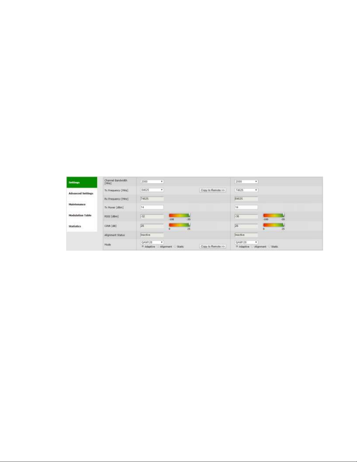
Figure 4-1 Radio Page: Settings
This section allows configuring the following parameters:
Channel Bandwidth [MHz] – 250, 500, 1250 or 2000MHz (model dependent).
Default is 2000MHz.
Tx Frequency [MHz] – transmit frequency.
o Country : Approved Frequency list per country regulation rules
(model dependent).
[Default = Worldwide. All available Frequencies]
i.e. Choosing a country from the picklist will enable only the allowed
channels in this country.
Rx Frequency [MHz] – R/O field, updated based on Tx frequency. Fixed 10GHz
spacing between Tx and Rx frequencies.
Tx Power [dBm] – radio’s transmit power. Default is the max power, based on
product’s specs. Minimum configurable Tx power is -35dBm (note that actual
minimum Tx power is based on product’s specs).
Page 43
EtherHaul™ 8000 Installation, Operation and Maintenance Manual
Page 43
The Tx power value sets the transmit power for the highest modulation profile. In case
lower modulation profile(s) has higher max Tx power (based on product’s specs), the Tx
power will be increased automatically without indication in RF configuration menu.
Mode – operational mode of the link:
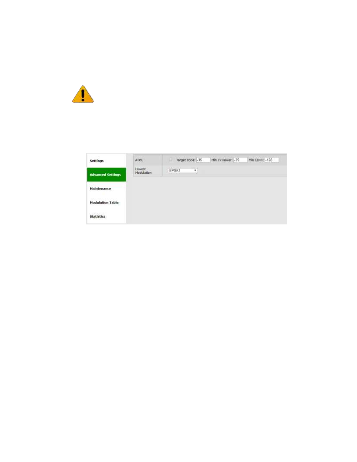
o Alignment – Carrier Wave transmission. Used for antenna alignment. No
data over the radio link.
During Alignment mode, the radio records and displays the max RSSI value it m easured
as an indication to the installer, allowing the installer to align the antennas optimally.
Figure 4-2 Radio Page: Settings in Alignment Mode
o Static – Fixed modulation profile. If you select Static, you must select from a
list of pre–configured modulation profiles in the Modulation field.
o Adaptive – Adaptive Bandwidth, Code, and Modulation.
The radio will work on the highest modulation profile based on the CINR
values of the both sides and will present the current modulation profile.
Adaptive mode is the normal and recommended mode of the radio link.
Note:
Adjust Tx Power so the RSSI at the remote end will not exceed -305dBm (overload
threshold).
Refer to the note below (Advanced Settings) regarding short range mode in case RSSI
exceeds -30dBm even after adjusting Tx power to the minimum.
Note:
When exiting Alignment mode, perform system reboot to allow proper operation of
the radio link.
Page 44
EtherHaul™ 8000 Installation, Operation and Maintenance Manual
Page 44
Alignment Status – R/O field, indicating that the ODU is currently in Alignment
mode (by configuration or by inserting DVM probes).
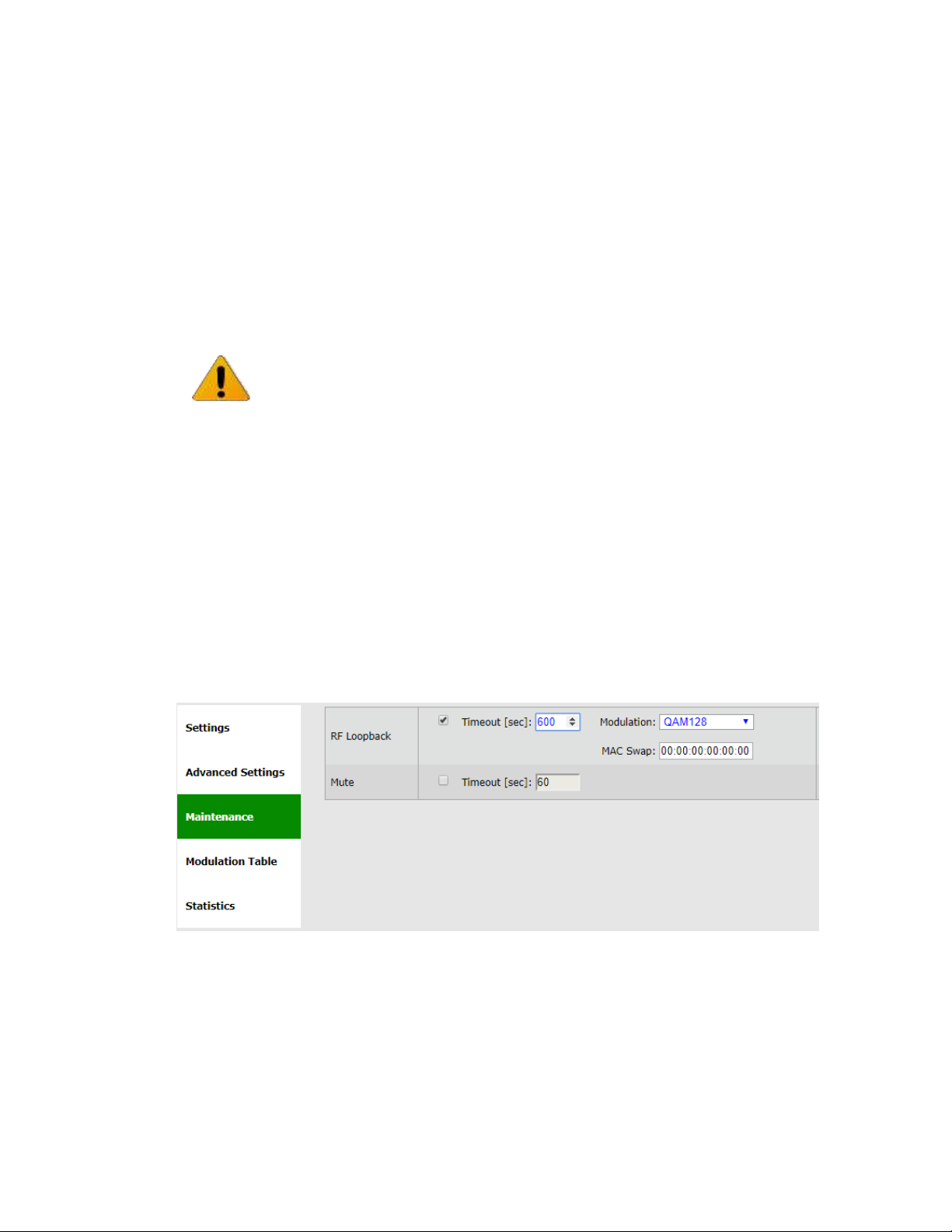
4.2 Advanced Settings
Figure 4-3 Radio Page: Advanced Settings
This section allows configuring the following parameters (options availability depends
on model):
ATPC – Automatic Transmit Power Control adjusts transmitter output power of
the local system based on the varying signal level at the remote receiver.
Note that ATPC support depends on product’s specs and SW release.
ATPC allows the transmitter to operate at less than maximum power for most of the
time and when fading conditions occur, transmit power will be increased as needed
until the maximum configured value is reached. ATPC messages are carried over the
radio over radio communication channel.
The purpose of ATPC is a) to reduce interference to other radios operation in the
same channel/band and to allow better frequency reuse; and b) to reduce
transmitter power consumption and prolong system’s components life.
ATPC is supplementary to adaptive modulation and works before adaptive
modulation changes modulation profiles.
Interference avoidance algorithm is implemented in order to overcome the main
drawback of use of ATPC: interference from other links that may degrade the radio
link performance. Besides setting the Target RSSI, the user can also set the Target
Note:
When changing Radio parameters of the link (like Mode, frequency…) the link will go
down and come up within couple of minutes.
Page 45
EtherHaul™ 8000 Installation, Operation and Maintenance Manual
Page 45
CINR that will notify the remote transmitter to increase its Tx power to maintain
CINR is above the threshold set.
Mode of operation: the local system compares the actual received RSSI to the ATPC
Target RSSI. If the difference in values is 2dB or higher (Delta=>2dB), a message to
remote transmitter will be sent, asking to change its Tx power.
The Tx power can be changed the system's configured Tx power down to the ATPC
Min Tx Power that was configured.
Configuration options:
o Checkbox to enable the ATPC operation.
o ATPC Target RSSI – allowed values -35 to -70 dBm (default -35 dBm).
o ATPC Min Tx Power – allowed values -35 to 0 dBm (default -35 dBm).
o Min CINR – allowed values -128 to 128 dB (default -128 dB).
Lowest Modulation – Lowest modulation profile. When modulation drops below
this threshold, radio link will be down. It is used to limit the minimal modulation
profile of the link. Default is BPSK 1 (lowest available).
4.3 Maintenance
Figure 4-4 Radio Page: Maintenance
This section allows configuring the following parameters:
RF Loopback – checkbox to enable the internal RF loopback, set the timeout for
clearing the loopback in seconds and select the modulation the ODU will be
tested at.
Note:
ATPC does not provide immunity from saturation. If running very short link, first
reduce Tx power so RSSI does not exceed -35dBm and then enable ATPC.
Page 46
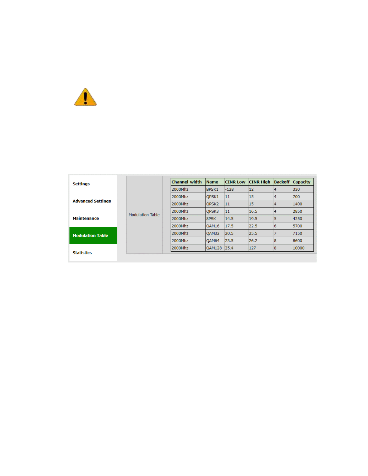
EtherHaul™ 8000 Installation, Operation and Maintenance Manual
Page 46
Note that it will take the ODU to stabilize after loopback up to 3 minutes so set the
loopback timeout accordingly (recommended 600 seconds).
Mute remote transmitter first to avoid interference with the loopback operation.
Refer to the Diagnostics chapter of this manual for detailed description of the
system’s loopbacks.
Mute – checkbox to mute the transmitter with timeout in seconds. When
muted, the ODU will not transmit.
4.4 Modulation Table
Figure 4-5 Radio Page: Modulation Table
The modulation table presents the available modulation profiles. The radio can be
configured only to one of the profiles available in the table.
CINR Low – Lower threshold for stepping down in modulation profile (Adaptive
Mode).
CINR High – Upper threshold for stepping up in modulation profile (Adaptive
Mode).
Note that different modulation tables may apply according to product used.
The modulation profiles and thresholds are optimized and cannot be modified.
Note:
Loopback is performed with MAC addresses swap (swapping DA and SA) for the
address specified only. All other MAC addresses not looped.
Page 47
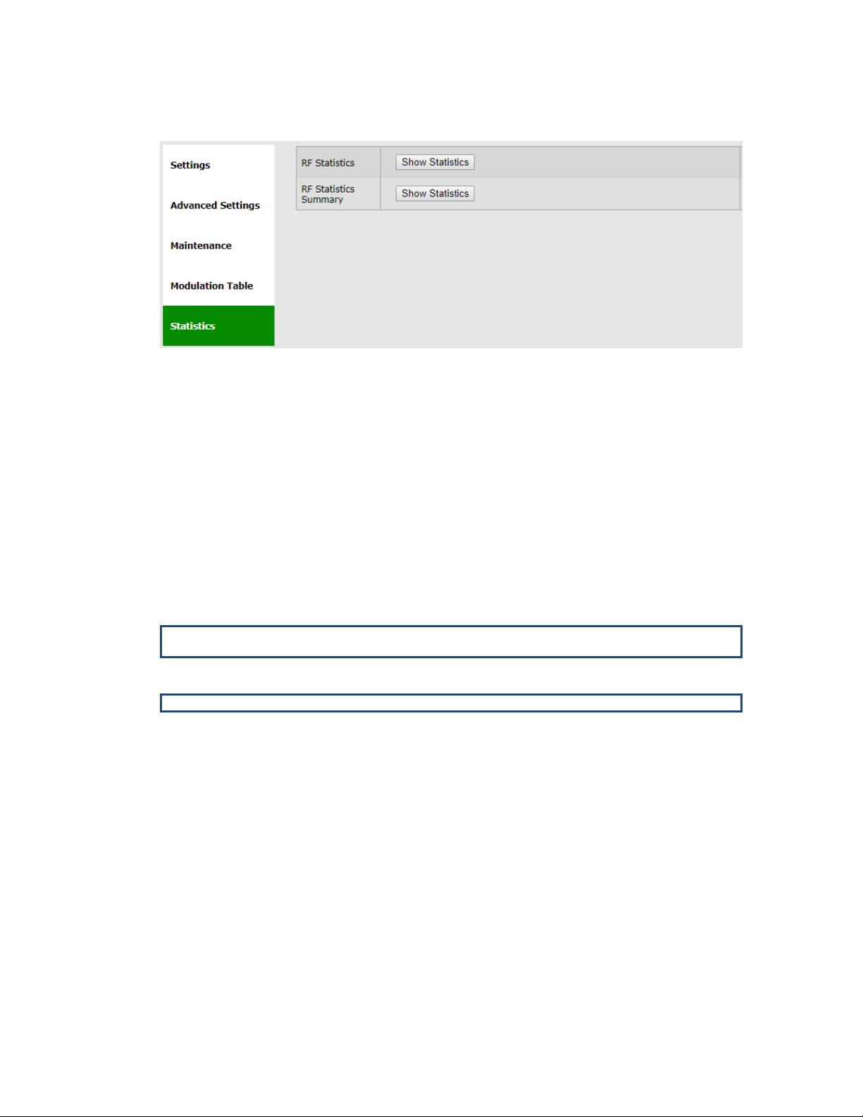
EtherHaul™ 8000 Installation, Operation and Maintenance Manual
Page 47
4.5 Statistics
Figure 4-6 Radio Page: Statistics
Radio link’s performance can be monitored using the advanced statistics counters.
Click View Statistics to review the local and remote RF Performance Monitoring
statistics. Clicking View Statistics will open the Statistics page where all system’s
statistics can be reviewed.
Refer to the Statistics chapter of this manual for detailed description of the system’s
statistics.
4.6 CLI Commands
Monitoring the RF configuration and status:
Show rf
Viewing the modulation table:
Show modulation
Page 48
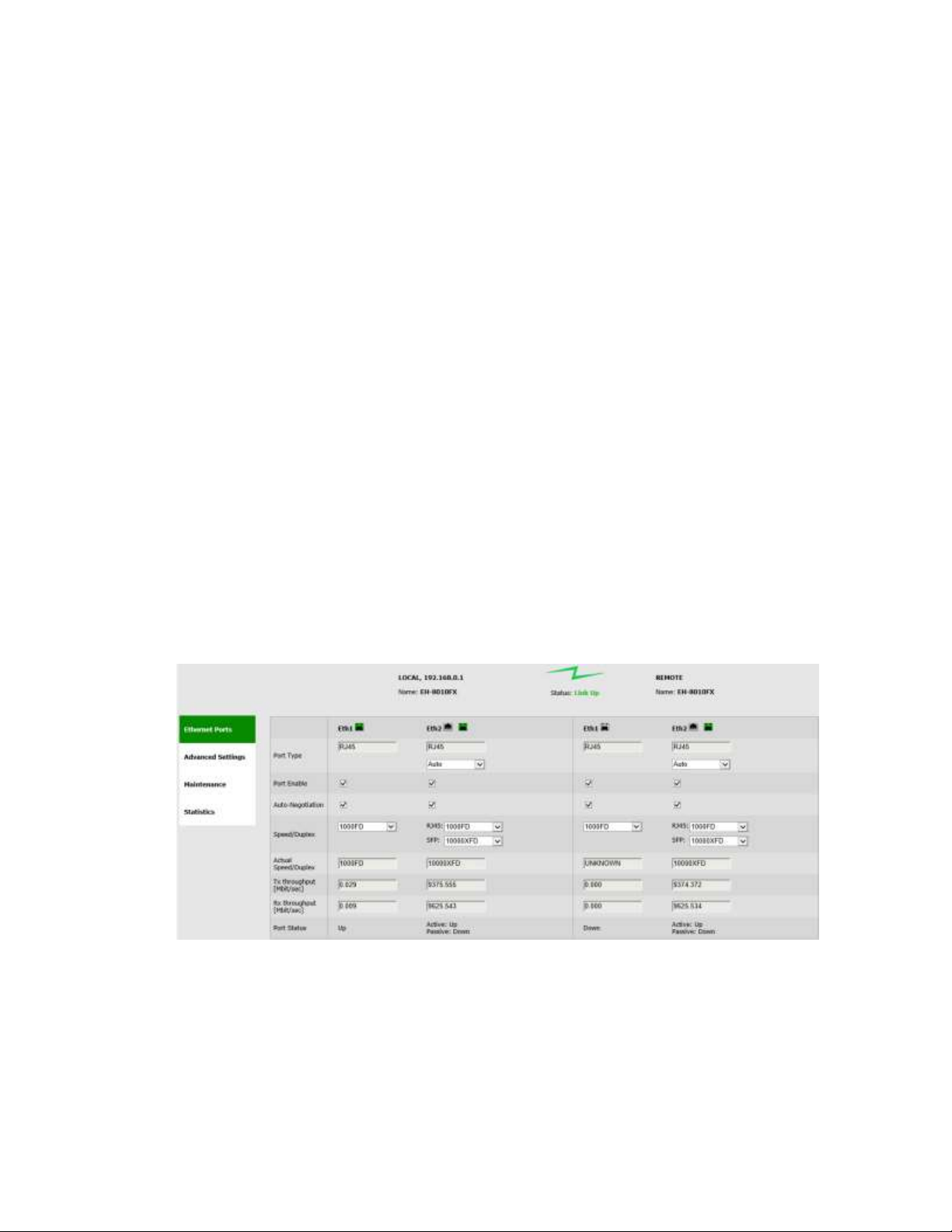
EtherHaul™ 8000 Installation, Operation and Maintenance Manual
Page 48
5 Ethernet Ports Configuration and Monitoring
The Ethernet ports parameters and monitoring are managed in the Eth Ports page.
The radio has the following Ethernet interfaces:
Host – Management interface (internal bridge port)
Eth0 – Radio (RF) interface (internal bridge port)
Eth1 – Line interface, 1GE port
Eth2 – Line interface, 10GE combo ports (refer to the active port of the two)
o RJ45 electrical (802.3an/bz)
o SFP+ optical (SM or MM)
This chapter includes the following topics:
Settings
Advanced Settings
Maintenance
Statistics
CLI commands
5.1 Settings
Figure 5-1 Eth Ports Page: Settings
This section allows configuring the following parameters:
Port Type – RJ45 or SFP based on the physical port.
Eth1 1GE is fixed RJ45. For Eth2 10GE combo port, you can choose to work with
RJ45 or SFP+ or choose Auto that will automatically select (and fail over) to the
Page 49
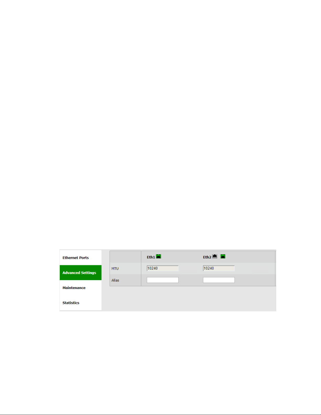
EtherHaul™ 8000 Installation, Operation and Maintenance Manual
Page 49
active port (if both 10GE inputs are available, radio will choose to use the RJ45
10GE input).
Port Enable – checkbox to enable the port.
Disable ports that are not in use so alarm will not be active (link down alarm).
Auto Negotiation – checkbox to enable auto-neg.
Speed/Duplex – speed (10/100/1000/10000) and duplex (half/full) setting:
o When Auto Negotiation Enabled – R/O field indicating the current
speed/duplex.
For the 10GE combo port, in case port type is set to ‘Auto’, the speed/duplex
displayed will be for the active port.
o When Auto Negotiation Disabled – manual configuration of the speed and
duplex
1GE port: 10HD, 10FD, 100HD, 100FD, 1000HD or 1000FD
10GE RJ45 port: 100HD, 100FD, 1000HD, 1000FD, 2500FD, 5000FD,
10000FD
10GE SFP+ port: 10000XFD.
Tx and Rx Throughput (Mbits/sec) – last second throughput
Port status – Up or Down.
Note that for the 10GE combo port, ther status refer to either ‘Active’ pr
‘Passive’ ports (based on the port configuration option (RJ45, SFP+ or Auto).
5.2 Advanced Settings
Figure 5-2 Eth Ports Page: Advanced Settings
This section allows configuring the following parameters:
MTU – R/O field indicating the Maximum Transmission Unit of the port.
10,240 bytes.
Alias – text field
Page 50
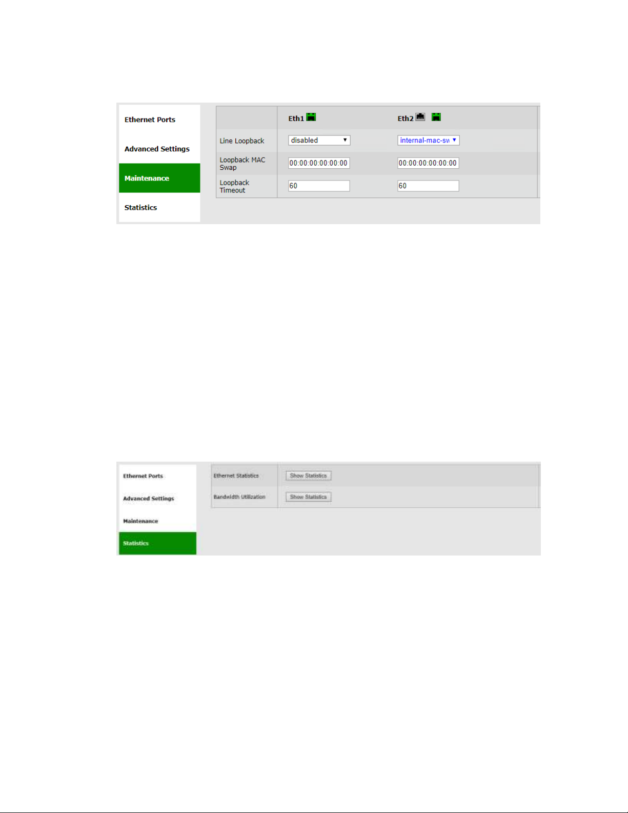
EtherHaul™ 8000 Installation, Operation and Maintenance Manual
Page 50
5.3 Maintenance
Figure 5-3 Eth Ports Page: Maintenance
This section allows configuring the following parameters:
Line Loopback – checkbox to enable loopback on the port. Internal (towards the
radio side) loopback is available, with specific MAC addresses swap.
Loopback MAC Swap – Loopback is performed with MAC addresses swap
(swapping DA and SA) for the address specified only. All other MAC addresses
not looped.
Loopback Timeout – in seconds. Loopback will clear when timeout expires.
Refer to the Diagnostics chapter of this manual for detailed description of the system’s
loopbacks.
5.4 Statistics
Figure 5-4 Eth Ports Page: Statistics
Ethernet performance can be monitored using the advanced statistics counters.
Click View Statistics to review the local and remote Ethernet Performance
Monitoring statistics. Clicking View Statistics will open the Statistics page where all
system’s statistics can be reviewed.
Refer to the Statistics chapter of this manual for detailed description of the system’s
statistics.
Page 51

EtherHaul™ 8000 Installation, Operation and Maintenance Manual
Page 51
5.5 CLI Commands
Monitoring the Ethernet ports configuration and status:
Show eth
Setting Ethernet port type auto (both 10GE ports):
set eth eth2 active-port auto
Page 52
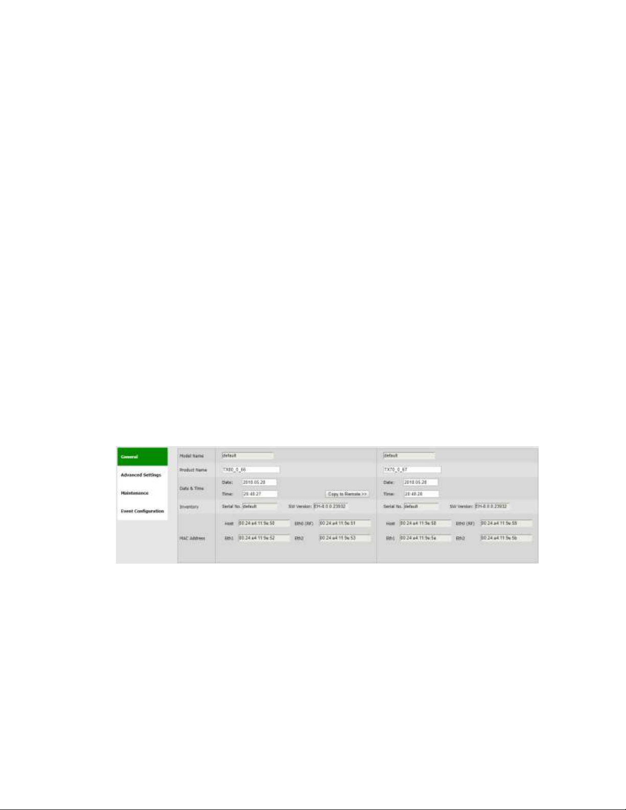
EtherHaul™ 8000 Installation, Operation and Maintenance Manual
Page 52
6 System Configuration and Monitoring
The system general parameters and monitoring is managed in the System page.
This chapter includes the following topics:
Settings
Advanced Settings
Maintenance
Event Configuration
CLI commands
The Maintenance section consists of the system's configuration files and file-system
management, including:
File Transfer
SW Upgrade
Licensing
Scripts
Configuration Management
6.1 Settings
Figure 6-1 System Page: Settings
This section allows configuring the following parameters:
Model – R/O field.
Name
Date & Time – Date [YYYY.MM.DD], Time [HH:MM:SS]
Page 53
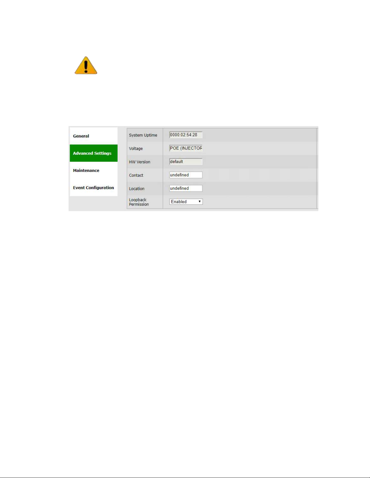
EtherHaul™ 8000 Installation, Operation and Maintenance Manual
Page 53
Inventory – R/O fields. Serial Number and active SW version.
MAC Address – R/O fields for each port.
6.2 Advanced Settings
Figure 6-2 System Page: Advanced Settings
This section allows configuring the following parameters:
System Uptime – R/O field. Time elapsed from last power on.
Voltage – R/O field. Input voltage and indication DC or PoE.
HW Version – R/O field.
Contact – text.
Location – text.
Loopback Permission – control the permission to perform system loopbacks
o Enabled (default): all loops allowed.
o Disabled: no loops allowed.
o MAC-SWAP: only loops with MAC-SWAP allowed.
Note:
Full inventory information of the system is stored as a file (inventory.ini) in the File
System and can be retrieved by the user.
Page 54
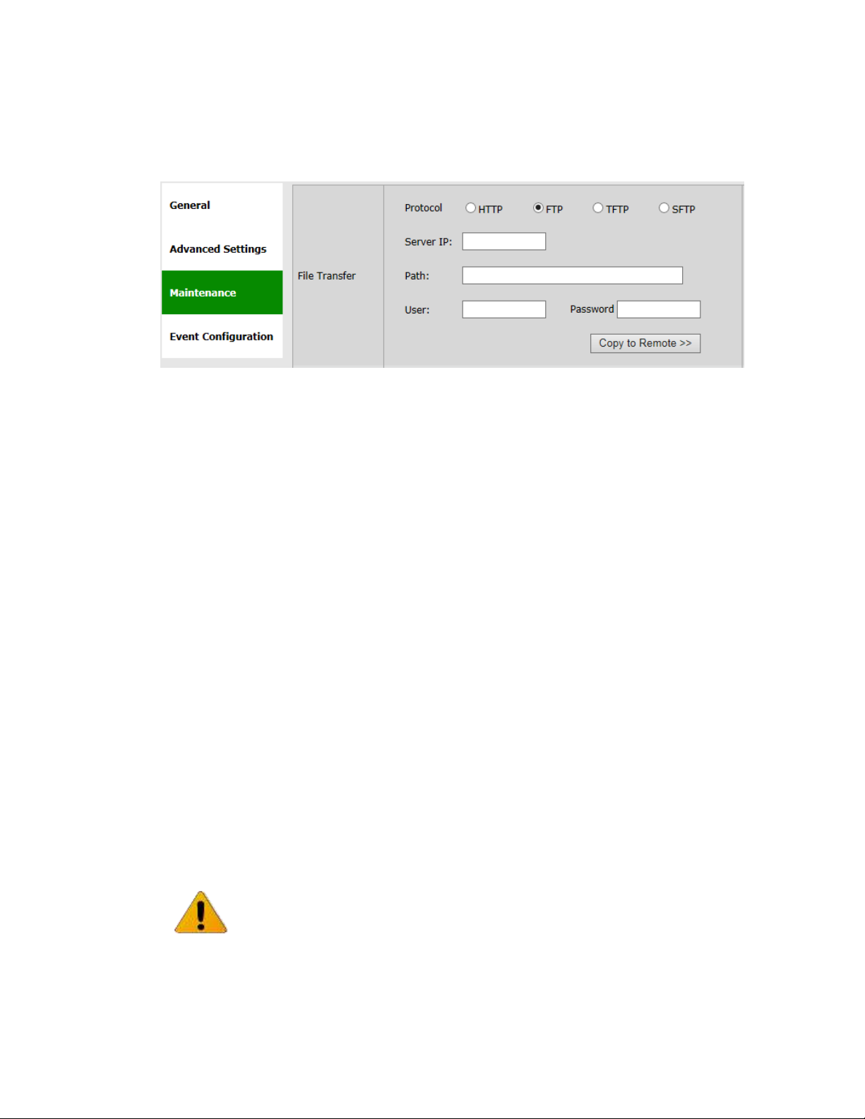
EtherHaul™ 8000 Installation, Operation and Maintenance Manual
Page 54
6.3 Maintenance
6.3.1 File Transfer
Figure 6-3 System Page: Maintenance – File Transfer
The administration of the file system is controlled by the File Transfer session. It
includes the configuration files, SW version, licenses, scripts, inventory and more.
File transfer is available over HTTP when using the web-GUI. In this case, no external
FTP, TFTP or SFTP server is required for file transfer.
In order to transfer files over FTP/TFTP/SFTP, FTP/TFTP/SFTP server must be running
and the file transfer attributes must be configured.
This section allows configuring the following parameters:
Protocol – HTTP, FTP, TFTP or SFTP.
Server IP – the IP address of the server where the FTP/TFTP/SFTP server is
running on.
Path – the path of the stored file (or target destination) relative to the directory
used for file transfers as configured in the server. If left blank, file transfer will
be from/to the server's Root (or Home) directory.
User – user name, as defined in the server. Leave blank if anonymous user
defined.
Password – password, as defined in the server. Leave blank if anonymous user
defined.
Note:
The simplest and recommended way to transfer files is using HTTP file transfer.
In cases when using the CLI, use FTP (make sure that the FTP service is free and not
blocked by Firewall/Antivirus or occupied by other software or services) or TFTP
(often not blocked or used by other software services).
Page 55
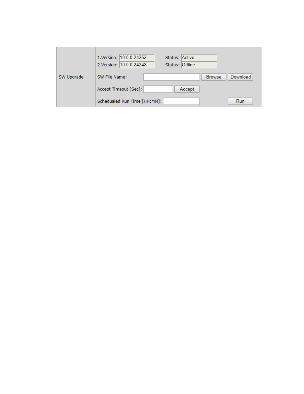
EtherHaul™ 8000 Installation, Operation and Maintenance Manual
Page 55
6.3.2 SW Upgrade
Figure 6-4 System Page: Maintenance – SW Upgrade
The system supports two software version, maintaining an Active (running) and an
Offline (standby) software versions (banks) that allow software upgrade with minimum
service interruption.
The software upgrade process consists of 3 steps:
1) Download. Transferring the new software file to the system (to the offline
software bank).
2) Upgrade. Switching the active status between the banks so the downloaded
software becomes active.
3) Accept. Use timeout to verify that the new active software performs as
expected and accept the upgrade to make it permanent (optional).
The SW Upgrade section displays the software versions currently resides in the banks
and their status (Active or Offline).
The software may be downloaded done using HTTP or an external FTP/TFTP/SFTP
server. Refer to server's configuration as defined in the File Transfer section.
This section allows configuring the following parameters:
SW File Name – The name of the software file to download.
Accept Timeout [Sec] – time out in seconds in which the new software should be
accepted. If the new software is not accepted within the timeout period, the
system will reboot and rollback to the previously active software. It is
recommended to use 600 seconds timeout whenever upgrading a software.
Scheduled Run Time [HH:MM] – enter time of day (hours:minutes) that the SW
upgrade will be performed (and the reboot). Allows sending upgrade command
to the radio that will be scgeduled to a later hour (maintenance window out of
working hours).
Page 56
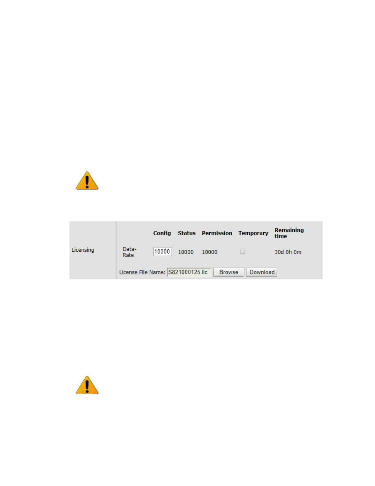
EtherHaul™ 8000 Installation, Operation and Maintenance Manual
Page 56
It is important that you set correct system time and date on your network for a
scheduled run time.
Click Download to start the software download from the server to the system.
Click Upgrade to activate the downloaded software. If you have specified time for
the upgrade (Scheduled Run Time [HH:MM]), the software will be activated at this
time. If you have not specified such time, the downloaded software will be activated
immediately.
Note that this action will result in system reboot.
Click Accept to accept the new SW.
6.3.3 Licensing
Figure 6-5 System Page: Maintenance – Licensing
The system provides easy migration to support Gigabit throughput and advanced
features, enabling operators to enhance bandwidth capacity on a “pay as you grow”
basis as well as adding features and capabilities according to their networks evolutions.
The following licenses may be purchased:
Data rate (capacity) – 2000, 5000 or 10000 Mbps
The license upgrade key is a signature file containing the license configuration that is
based on the system's serial number. License file is provided as a text file that can be
Note:
Always upgrade both sides!
When upgrading an operational link, upgrade the remote system first and then the
local system. Accept the software at both ends after verifying that the link performs
as expected.
Note:
The data rate license active on the system dictates the highest modulation profile the
link will reach.
Page 57

EtherHaul™ 8000 Installation, Operation and Maintenance Manual
Page 57
opened with any text editor. The license file name will always be
<system_serial_number>.lic.
The license upgrade is done using HTTP or an external FTP/TFTP/SFTP server. Refer to
server's configuration as defined in the File Transfer section.
The license upgrade process consists of 2 steps:
1) Download. Transferring the new license file to the system.
2) Enable. Enabling the license components. Note that if you restore factory
default configuration, the system will come up with the available license
components enabled.
The system supports temporary license that is available for 30 days. Once enabled, a
countdown timer will run as long as the system is powered up. When timer expires, the
system will reboot and come up with data rate /functionality based on the available
license.
The temporary license can be enabled/disabled for each license component indiv idually.
Caution:
Use temporary license with caution and do not forget to apply permamnent license.
If the 30 day expire before adding permamnent license, link might go down or sume
essential functionality, controlled by license, will be disabled, what might impair
service.
The Licensing section displays the current configuration of the license components
(data-rate and features enable/disable) and states if license component is available
(permission).
The License File Name is an R/O field that will always be according to the
system's serial number (<system_serial_number>.lic).
Click Browse and Downoad to select and download a new license file. As the license
file name is always <system_serial_number>.lic, it will be displayed as the License File
Name.
The Permission field indicates rate/functionality availability based on the license file.
Use the Config field to set up the desired rate or to enable/disable functionality.
The Status field indicates rate/functionality base on license (Permission),
configuration (Config) and temporary license activation.
Note:
Enabling license components will introduce a momentary service disruption.
Page 58
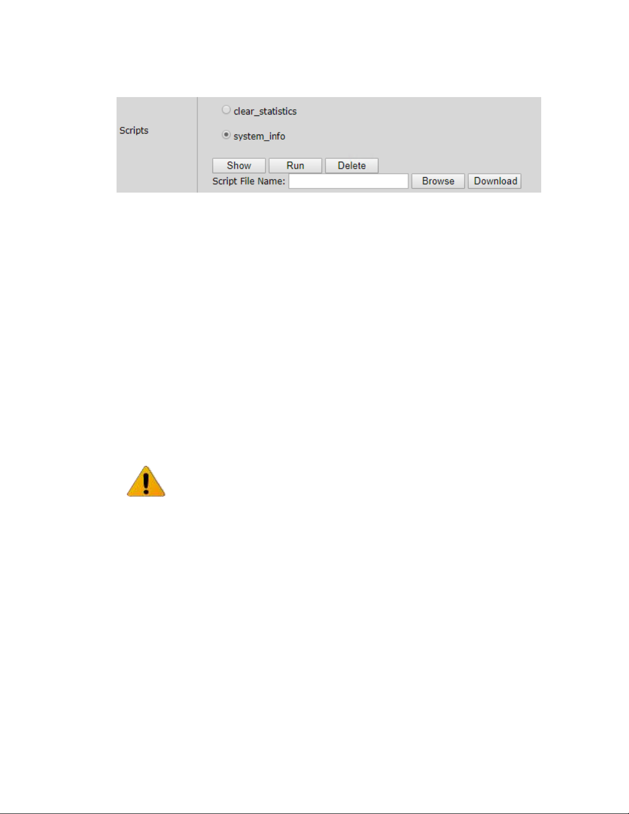
EtherHaul™ 8000 Installation, Operation and Maintenance Manual
Page 58
6.3.4 Scripts
Figure 6-6 System Page: Maintenance – Scripts
The system supports the use of pre-composed, multiple-line command scripts.
A script is simply a list of CLI commands, saved as a text file that runs locally on the
system. Script output is displayed on a script output screen and can be copied and
saved.
The Scripts section displays the scripts that were loaded to the system.
There are useful scripts that are pre-loaded to the system in the factory:
1) clear_statistics – this script clears all the statistics counters of the system,
including RF statistics, Ethernet statistics, VLAN statistics and Queue
statistics.
2) System_info – this script collects all the relevant system status, logs,
configurations and statistics.
Select a script from the list and click Show to view (pop-up screen) list of commands
composing this script.
Click Run to run the selected script. The commands in the script will be executed
one after the other. Pop-up screen will display the progress and outcome of the
script.
Click Delete to delete the selected script.
Click Browse and Download to download a new script file to the system.
Note:
Whenever contacting us for support, send the output of this script from both
systems for efficient service (copy the output to a text file).
Page 59
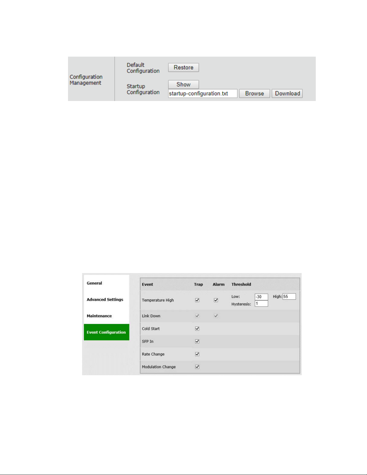
EtherHaul™ 8000 Installation, Operation and Maintenance Manual
Page 59
6.3.5 Configuration Management
Figure 6-7 System Page: Maintenance – Configuration Management
This section allows configuring the following parameters:
Default Configuration – Click Restore to delete current startup-
configuration.txt file. After reboot, the system will come up with the factory
default configuration (unless customer_default_config.txt file is present).
Startup Configuration – Click Show to view (pop-up screen) the startup-
configuration.txt file. The startup-configuration file lists the commands that
build the configuration the system will come up with after reboot.
Click Load to load a new startup-configuration file that will replace the current
file and will be used after next system reboot.
When clicking Load, the system will look for a file named startup-
configuration.txt at the FTP directory and will store it in the file system (flash:)
as the new startup-configuration file. After next reboot, the system will come up
with the new configuration.
6.4 Event Configuration
Figure 6-8 Network Page: Event Configuration
The system supports masking of individual/group alarms and events. In case alarm is
masked, it is not displayed in the Active Alarms and Event Log and no trap is sent.
Page 60

EtherHaul™ 8000 Installation, Operation and Maintenance Manual
Page 60
By default, none of the alarms are masked but the RSSI, CINR and Lowest
Modulation threshold-crossing alarms. In addition, some alarms have configurable
thresholds to raise and clear alarm.
This section allows configuring the following parameters:
Event – the event/group of events to be configured
Trap – checkbox to enable sending SNMP trap for this event.
Alarm – checkbox to enable raising an alarm for this event (meaning, showing it
in the active Alarms list and in the log file). Note that not all events can be
configured as Alarms.
Threshold – the following events have configurable thresholds for alarm
raise/clear and for sending traps. The threshold hysteresis can be defined (to
avoid toggling alarms).
o Temperature – when system temperature exceeds the High or Low
thresholds. Note that system temperature is typically 15-25°C higher then
ambient temperature.
Refer to the Alarms section under Diagnostics chapter of this manual for detailed
description of the system’s alarms.
6.5 CLI Commands
View system settings:
Show system
Restoring factory default configuration:
clear startup-configuration
reset system
Viewing the startup configuration
copy startup-configuration display
Viewing the currently running configuration
copy running-configuration display
Loading new startup configuration (for example, using FTP):
copy ftp://<ftp_user>:<ftp_password>@<ftp_server_ip>/startupconfiguration.txt flash:startup-configuration.txt
Downloading SW (for example, using FTP):
copy sw ftp://<ftp_user>:<ftp_password>@<ftp_server_ip>/<sw_file_name>
Page 61

EtherHaul™ 8000 Installation, Operation and Maintenance Manual
Page 61
Upgrading and accepting SW:
run sw immediately 600
accept sw
Scheduling Upgrade time (at the coming 4 am):
run sw scheduled 04:00
Viewing inventory:
Show inventory
Viewing list of scripts:
show script
Deleting script:
clear script <script_name>
Loading a new script (for example, using FTP):
copy ftp://<ftp_user>:<ftp_password>@<ftp_server_ip>/<script_file_name>
flash:scripts/<script_file_name>
Page 62
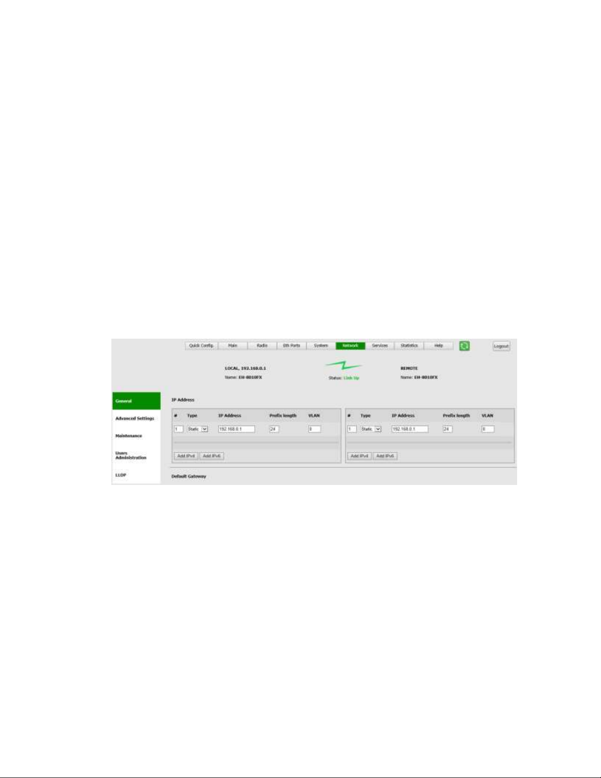
EtherHaul™ 8000 Installation, Operation and Maintenance Manual
Page 62
7 Network Configuration and Monitoring
General parameters regarding communication and network connectivity are managed in
the Network page.
This chapter includes the following topics:
General Settings
Advanced Settings
Maintenance
Users Administration
LLDP
CLI Commands
7.1 General
7.1.1 IP Address
Figure 7-1 Network Page: General – IP Address
The system supports up to four IP addresses that can be associated with different
VLANs. IPv4 or IPv6 can be configured. IP addresses may also be acquired by DHCP.
This section allows configuring the following parameters:
# - Index (1-4)
Type – Static or DHCP
IP Address – Default is 192.168.0.1
IP Prefix Length – Default is 24 (equivalent to Mask of 255.255.255.0)
VLAN – 0 (not defined, meaning the IP is not associated with specific VLAN)
Page 63
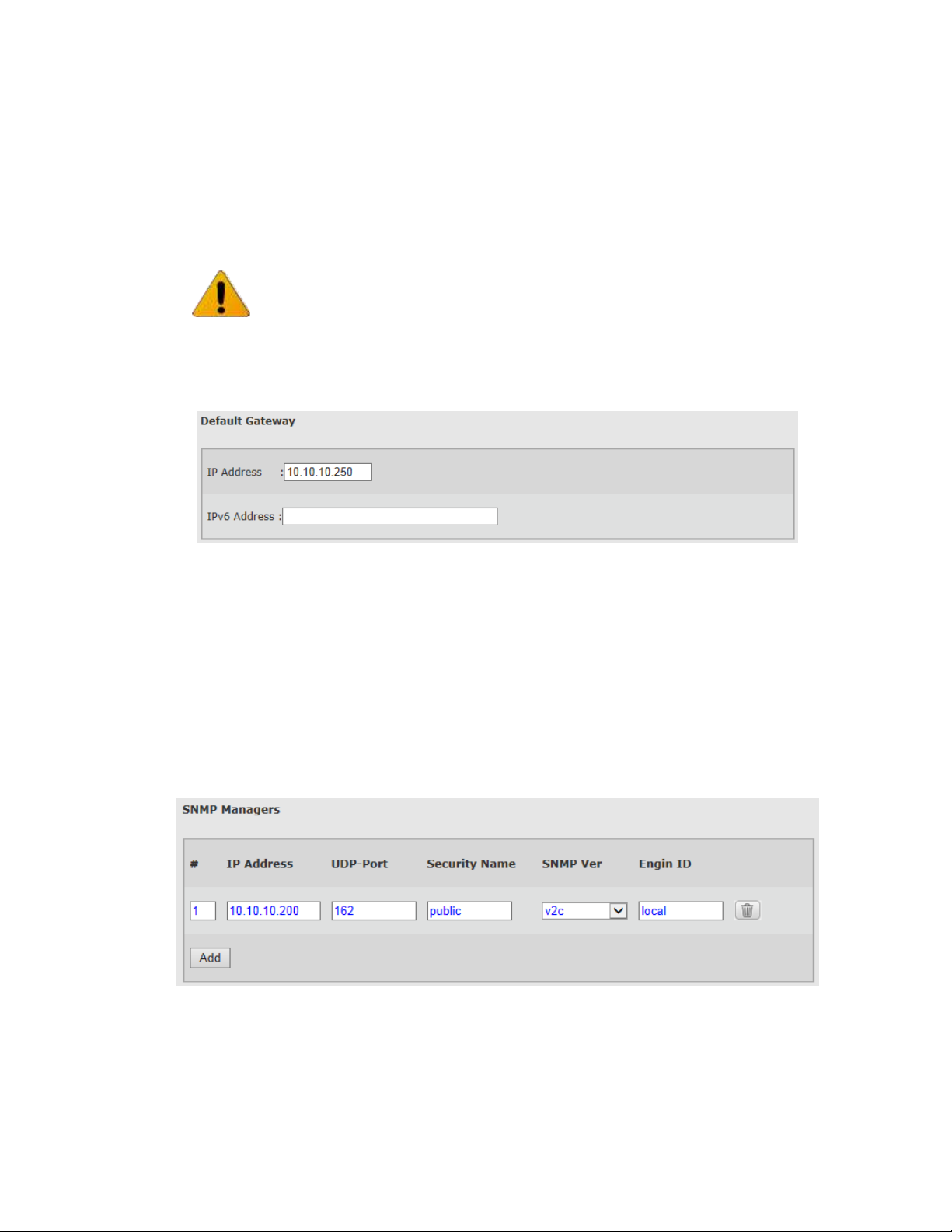
EtherHaul™ 8000 Installation, Operation and Maintenance Manual
Page 63
Click the Add IPv4 or Add IPv6 to add an IP address.
Click the Trash icon to clear an IP. Note you cannot clear the IP address you used to
log in to the system.
7.1.2 Default Gateway and Static Routes
Figure 7-2 Network Page: General – Default Gateway
This section allows configuring a single default gateway for IPv4 and IPv6.
The system allows defining up to 10 static routes, in which you can define the network
(Destination + Prefix-length) and the Next-Hop.
When entering default gateway, it is translated to a static route (#1).
Setting and viewing static routes is available via the CLI only.
7.1.3 SNMP Managers
Figure 7-3 Network Page: General – SNMP Managers
Note:
It is recommended to leave the default IP address (#1) and add the unique IP address
as #2. This will allow users to login to the system when on site even if they do not
know the configured IP of the system.
Page 64
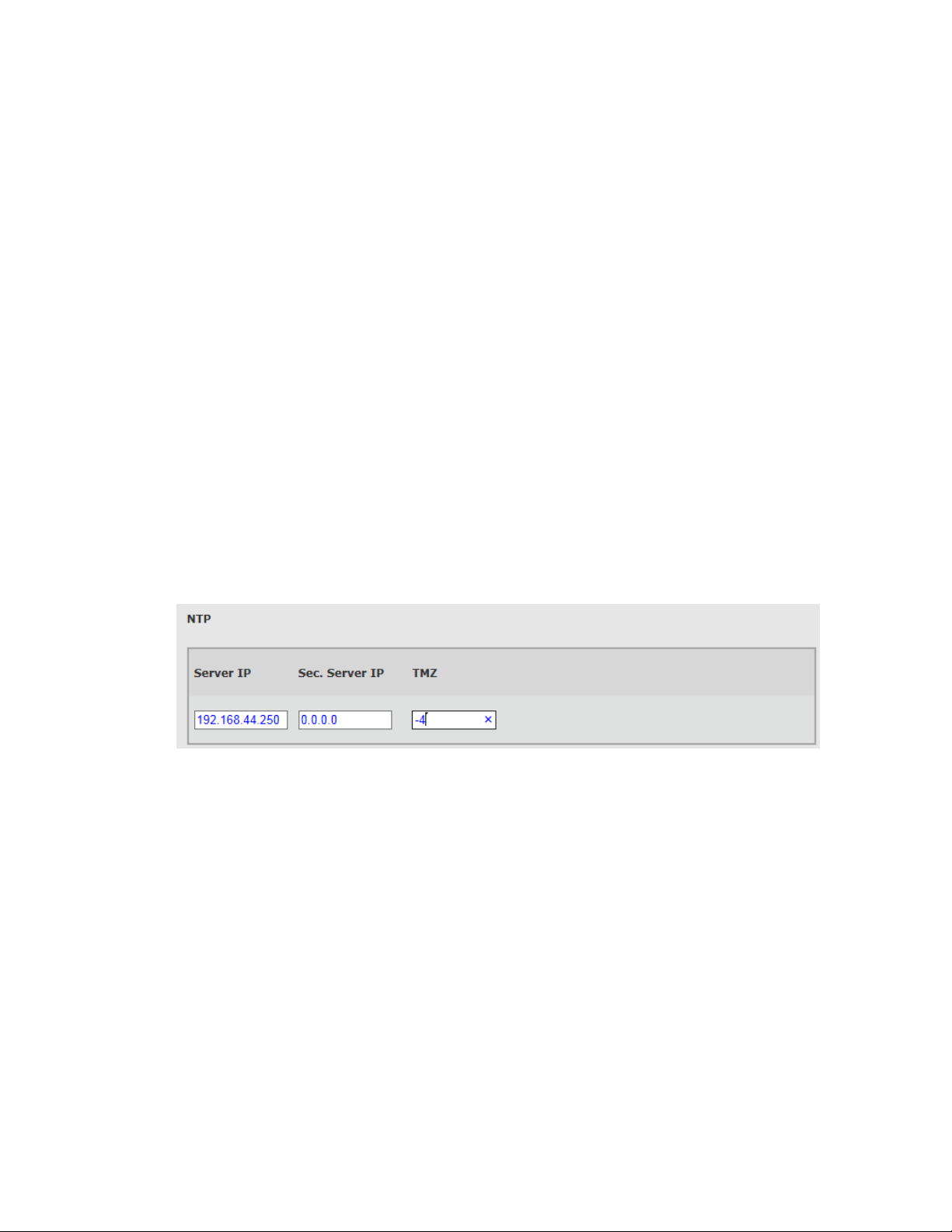
EtherHaul™ 8000 Installation, Operation and Maintenance Manual
Page 64
The System allows defining up to five managers that will receive SNMP traps. Traps can
be sent using SNMPv2c or SNMPv3.
This section allows configuring the following parameters:
# - Index (1-5).
IP Address – Destination IP Address.
UDP Port – port number for sending traps (default is 162).
Security Name (community) – same as the trap community name in SNMPv2c
and as the user name in SNMPv3 (default is public).
SNMP Ver – SNMP version: SNMPv2c or SNMPv3 (default is SNMPv2c).
Engine ID – Used for SNMPv3.
For SNMPv3 configuration, refer to the SNMPv3 Users Configuration section under
System Administration chapter of this manual.
Click the Add to add SNMP manager.
Click the Trash icon to clear SNMP manager.
7.1.4 NTP
Figure 7-4 Network Page: General – NTP
The Network Time Protocol (NTP) is a protocol for synchronizing the clocks of network
elements over packet-switched, variable-latency data networks.
NTP provides a connectionless service (UDP in the Transport Layer).
The System has an embedded NTP client. It can synchronize the host clock to any NTP
server in the LAN/Internet to deliver accurate and reliable time.
Primary and secondary servers can be defined.
This section allows configuring the following parameters:
Server IP – primary NTP server IP Address
Secondary Server IP – secondary NTP server IP Address
TMZ – time zone shift in hours (-12 to 14). Note that changing the TMZ value will
change the time entered.
Page 65
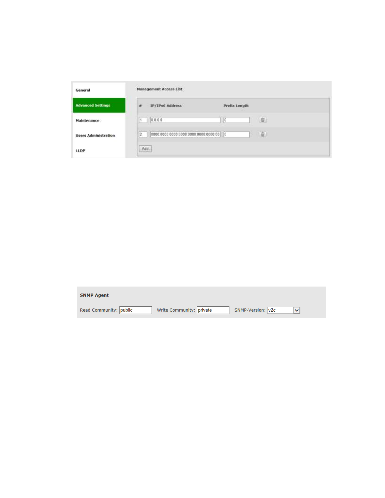
EtherHaul™ 8000 Installation, Operation and Maintenance Manual
Page 65
7.2 Advanced Settings
7.2.1 Management Access List
Figure 7-5 Network Page: Advanced Settings – Management Access List
List of authorized IPv4/IPv6 IP addresses (or IP address ranges) that are permitted to
access the Host (management).
The default configuration allows all IP address to access the Host.
This section allows configuring the following parameters:
# - Index (1-8)
IP Address
Prefix-Length – together with the IP address determine IP address range
7.2.2 SNMP Agent
Figure 7-6 Network Page: Advanced Settings – SNMP Agent
SNMP Agent properties (SNMP passwords).
This section allows configuring the following parameters:
Read Community – default is public. Used for Read access (SNMP Get).
Write Community – default is private. Used for Read/Write access (SNMP Set).
SNMP-Version – SNMPv2c or SNMPv3. Default is v2c.
Page 66
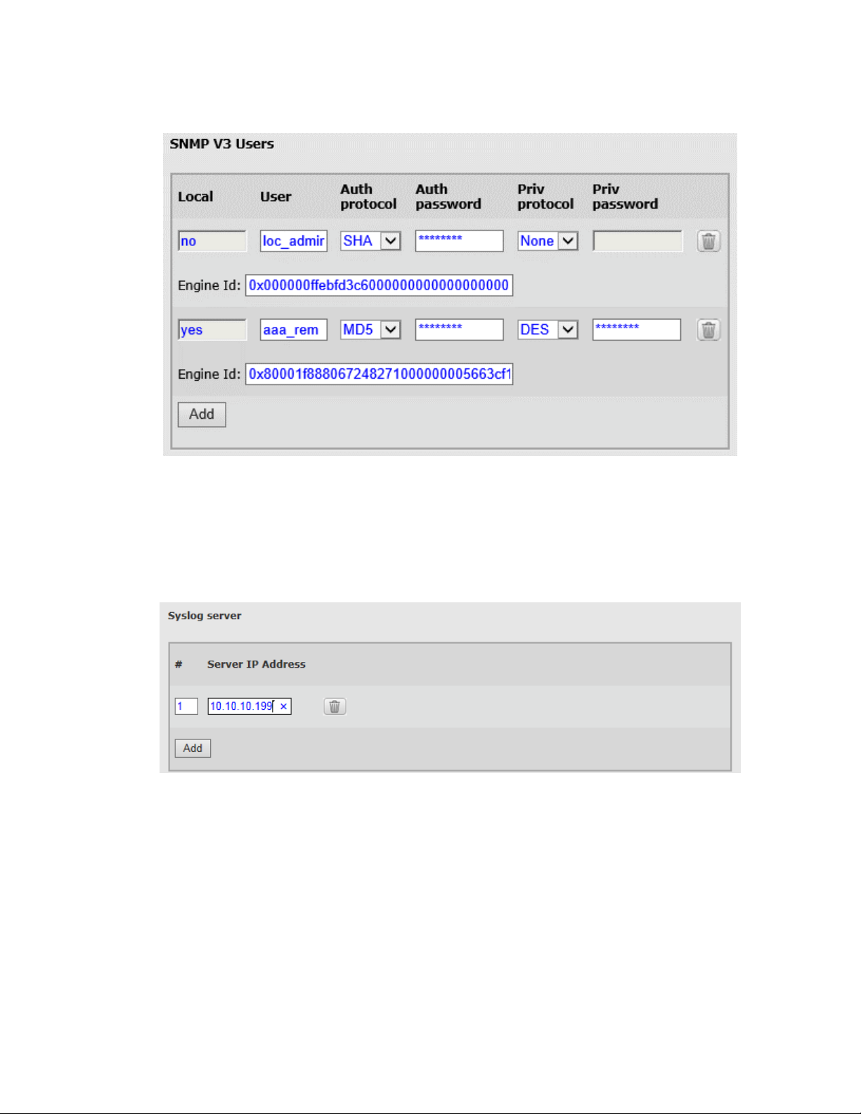
EtherHaul™ 8000 Installation, Operation and Maintenance Manual
Page 66
7.2.3 SNMP V3 Users
Figure 7-7 Network Page: Advanced Settings – SNMP V3 Users
Refer to section SNMPv3 Users Configuration under System Administration chapter of
this manual.
7.2.4 Syslog Server
Figure 7-8 Network Page: Advanced Settings – Syslog Server
When set, all system's event and alarms will be sent to servers. Up to 5 different Syslog
servers can be configured.
Syslog servers listen to Port 514.
Page 67
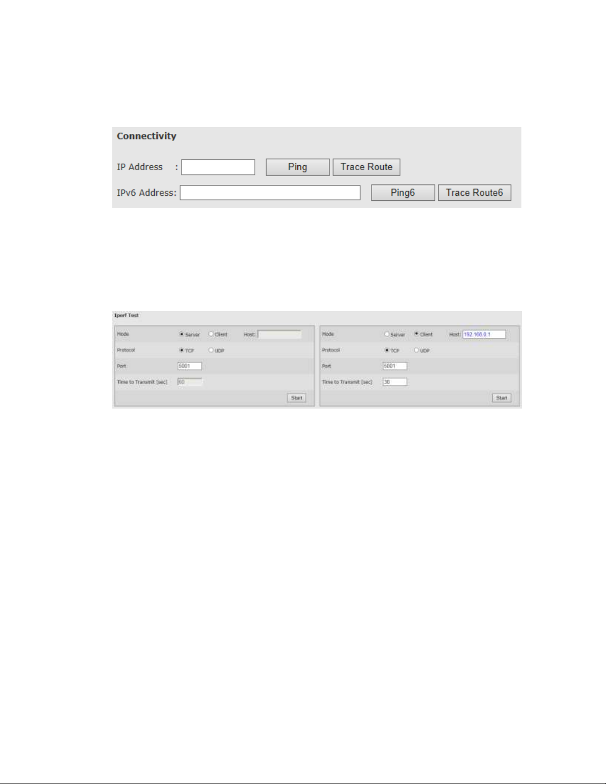
EtherHaul™ 8000 Installation, Operation and Maintenance Manual
Page 67
7.3 Maintenance
7.3.1 Connectivity
Figure 7-9 Network Page: Maintenance – Connectivity
Enter target IP address (IPv4 or IPv6) and click Ping or Trace Route to test
connectivity. Pop-up screen will display the results.
7.3.2 Iperf Test
Figure 7-10 Network Page: Maintenance – Iperf Test
Built-in Iperf client/server for over the link TCP/UDP test.
Configure one side as Server and run it (click Start) and remote end as Client (and enter
the server IP address).
Note that Iperf test run in parallel to traffic over the link.
Page 68
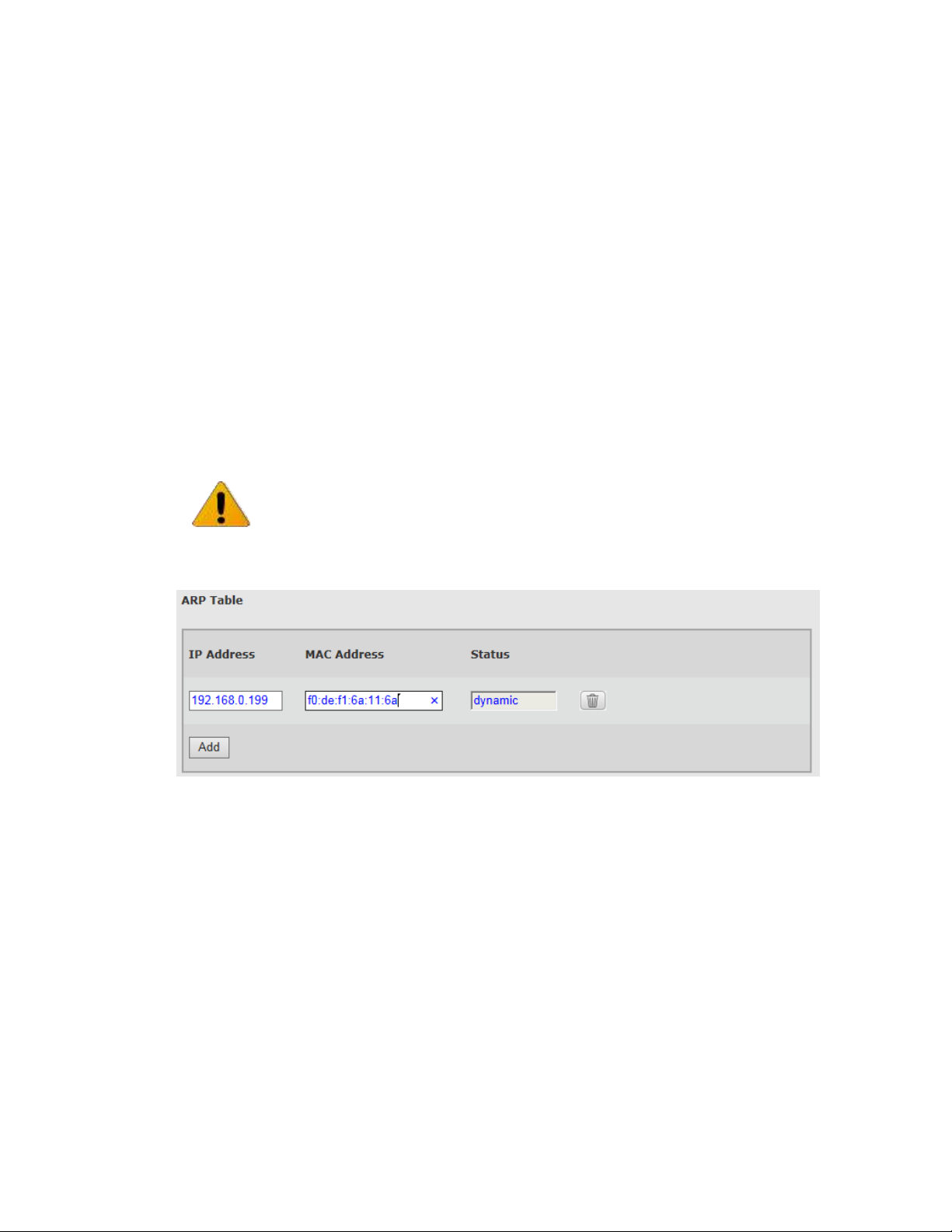
EtherHaul™ 8000 Installation, Operation and Maintenance Manual
Page 68
Iperf output:
-----------------------------------------------------------Server listening on TCP port 5201
-----------------------------------------------------------[ 6] local 192.168.0.251 port 5201 connected with 192.168.0.61 port 49996
[ ID] Interval Transfer Bandwidth
[ 6] 0.0- 1.0 sec 9.10 MBytes 76.3 Mbits/sec
[ 6] 1.0- 2.0 sec 9.60 MBytes 80.5 Mbits/sec
[ 6] 2.0- 3.0 sec 9.65 MBytes 80.9 Mbits/sec
[ 6] 3.0- 4.0 sec 8.73 MBytes 73.2 Mbits/sec
[ 6] 4.0- 5.0 sec 9.48 MBytes 79.5 Mbits/sec
[ 6] 5.0- 6.0 sec 9.94 MBytes 83.4 Mbits/sec
[ 6] 6.0- 7.0 sec 8.68 MBytes 72.8 Mbits/sec
[ 6] 7.0- 8.0 sec 9.68 MBytes 81.2 Mbits/sec
[ 6] 8.0- 9.0 sec 9.25 MBytes 77.6 Mbits/sec
[ 6] 9.0-10.0 sec 10.0 MBytes 84.1 Mbits/sec
[ 6] 10.0-11.0 sec 9.50 MBytes 79.7 Mbits/sec
7.3.3 ARP Table
Figure 7-11 Network Page: Maintenance – ARP Table
The ARP table is used to map between IP addresses and physical addresses. You can
map specific IP address to specific MAC address and create or modify entries in the ARP
table.
Note:
Iperf Test results are indicative only, and used to confirm that traffic is running over
the link. The expected results are ~50-100Mbps.
Page 69
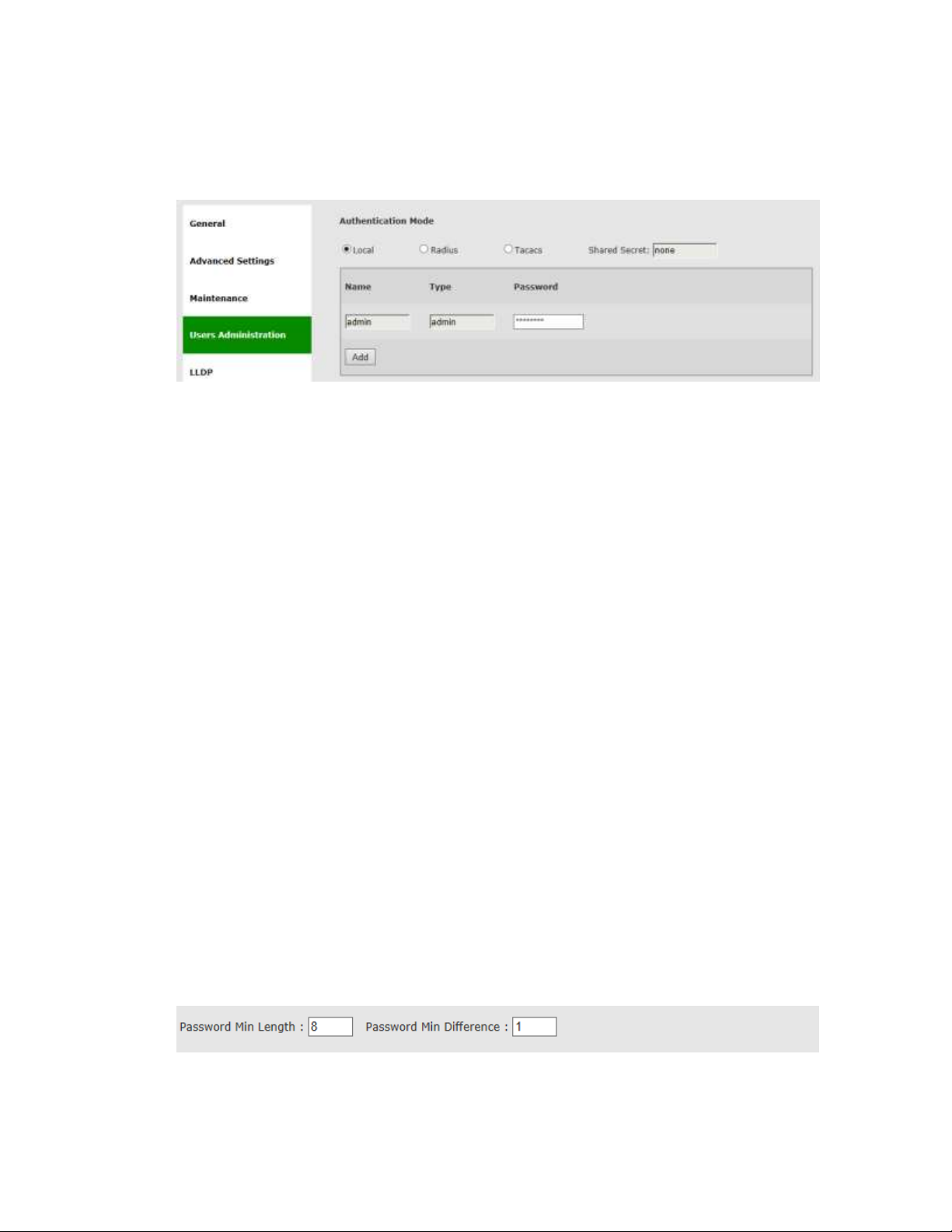
EtherHaul™ 8000 Installation, Operation and Maintenance Manual
Page 69
7.4 Users Administration
7.4.1 Users
Figure 7-12 Network Page: Users Administration – Local Authentication
Internal user management and external Radius or TACACS server are supported.
The Users administration page will be updated based on the selected Authentication
Mode.
For internal user management (standard user/passwords that are configured in the
device), select Local as the Authentication Mode.
The System supports 4 types of users that can be defined locally:
User – Read-only access. Cannot view user names, passwords, and other
security settings.
Tech – Read-only access for all configuration settings. Can clear statistics,
alarms, and log lists, and run diagnostics.
Super – Read-write access for all configuration settings but user names,
passwords, and other security settings.
Admin – Full read-write.
A single default admin user is defined with user name admin and password admin.
Up to 32 different users can be defined of different types. Note that only one admin
type user can be defined and the user name admin cannot be changed (only the
password can be changed).
For Radius or TACACS AAA configuration, refer to the TACACS+/RADIUS Users
Administration section under System Administration chapter of this manual.
7.4.2 Password Strength
Figure 7-13 Network Page: Advanced Settings – Password Strength
Page 70
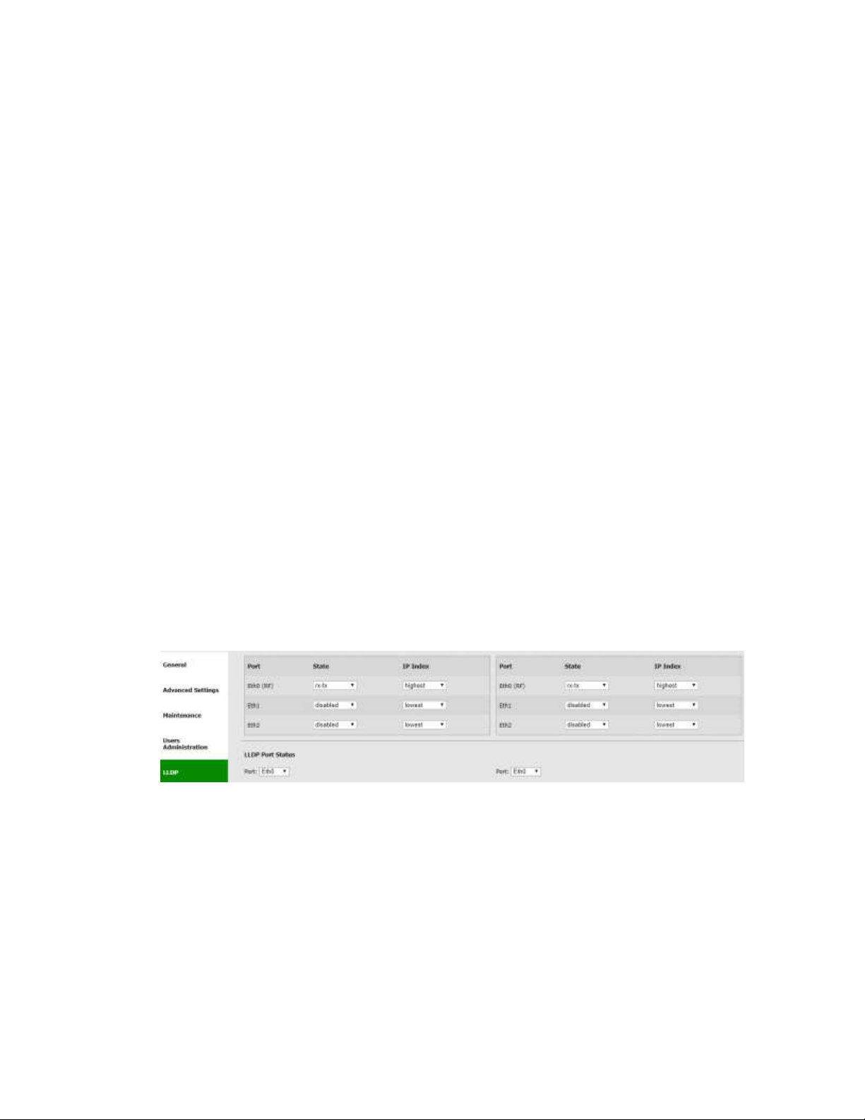
EtherHaul™ 8000 Installation, Operation and Maintenance Manual
Page 70
For password strength enforcement.
This section allows configuring the following parameters:
Password Min Length - minimum password length (0 to 16 characters). Default is
8.
Password Min Difference - minimum password difference between characters (0
to 5). Default is 1.
7.5 LLDP
The Link Layer Discovery Protocol (LLDP) is a unidirectional neighbor discovery protocol
(as per IEEE 802.1AB).
LLDP performs periodic transmissions of the system's capabilities to the connected
stations. LLDP frames are not forwarded, but are constrained to a single link. The
information distributed by the protocol is stored in a topology data base. This
information can be retrieved by the user in order to easily resolve the network’s
physical topology and its associated stations.
LLDP enables the discovery of accurate physical network topologies, meaning which
devices are neighbors and through which ports they connect. It enables the system to
discover other network elements that are connected to it, including the discovery of
third-party network elements, and enables easier integration of slinks in an LLDP
supported networks.
Note that LLDP support depends on product’s specs and SW release.
7.5.1 LLDP Configuration
Figure 7-14 Network Page: LLDP Configuration
LLDP can be configured for each one of the Ethernet ports, including the radio port
(Eth0). LLDP information may be sent over VLAN or without VLAN (untagged).
This section allows configuring the following parameters:
Port – Eth0 (RF), Eth1 (1GE), Eth2 (10GE)
Config – enabling LLDP on the port. Select rx-tx to enable LLDP. Note that you
may work with uni-directional LLDP by selecting rx or tx only.
Page 71
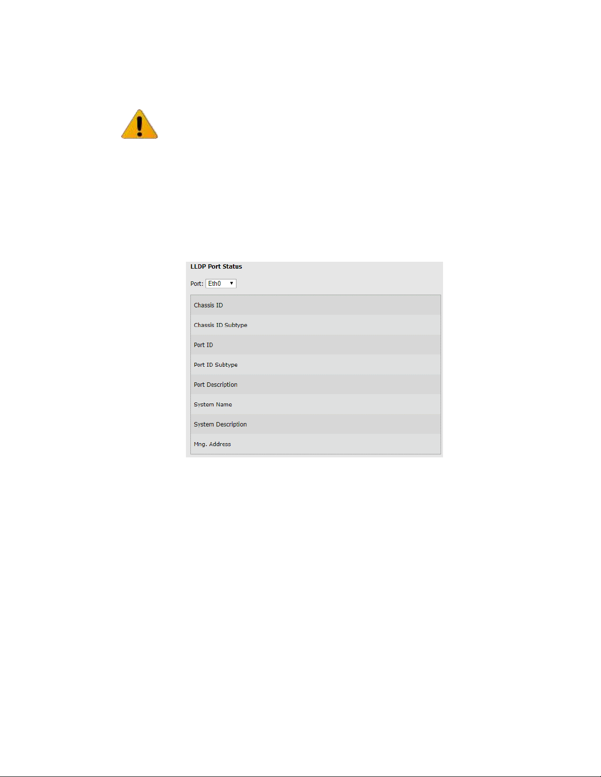
EtherHaul™ 8000 Installation, Operation and Maintenance Manual
Page 71
VID – VLAN ID that LLDP messages will be sent on. Default is none (untagged).
IP Index – Lowest, Highest or IP index (1-4). The IP address the system will
respond with in the LLDP information reply. Default is Highest.
7.5.2 LLDP Status
Figure 7-15 Network Page: LLDP Status
This section displays the information received from the peer device:
Chassis ID – displays the IP address (network address, typically refer to IP #1) of
remote device
Chassis ID Subtype – will be 'network-addr'
Port ID – displays the received MAC address
Port ID Subtype – will be 'mac-addr'
Port Description – The port connected at the peer device
System Name – of peer device
System Description – of peer device
Mng. Address – IP address that peer device reports. As there can be multiple IP
addresses, the device reports the IP address according to LLDP
Configuration: IP Index configured above.
Note:
By default, LLDP is enabled on the radio port (Eth0) and disabled on all line Ethernet
ports).
Disabling LLDP on all ports including the radio, will pass LLDP packets transparently
over the radio.
Page 72

EtherHaul™ 8000 Installation, Operation and Maintenance Manual
Page 72
7.6 CLI Commands
IP Addresses (IPv4):
Viewing IP addresses:
show ip
Setting IP address (static IP example):
set ip 2 ip-addr static 10.10.10.1 prefix-len 23 vlan 12
Setting IP address (DHCP example):
set ip 2 ip-addr dhcp
Deleting IP address:
clear ip 2
IPv6 IP Addresses:
Viewing IPv6 addresses:
show ipv6
Setting IPv6 IP address (static IP example):
set ipv6 2 ipv6-addr static 0001:0001:0001:0001:0001:0001:0001:0001
prefix-len 32 vlan 200
Deleting IPv6 address:
clear ipv6 2
Default Gateway and Static Routes:
Viewing default gateway and routes (IPv4):
show route
Viewing default gateway and routes (IPv6):
show route6
Setting default gateway and routes (IPv4):
set route 1 dest 0.0.0.0 prefix-len 0 next-hop 82.166.81.138
Setting default gateway and routes (IPv6):
set route6 1 dest 0001:0001:0001:0001:0001:0001:0001:0001 prefix-len 0
next-hop 0001:0001:0001:0001:0001:0001:0001:0002
SNMP Managers:
Viewing SNMP managers:
show snmp-mng
Setting SNMP managers:
set snmp-mng 1 ip-addr 192.168.0.250 udp-port 162 snmp-version v2c
security-name public
Deleting SNMP managers:
clear snmp-mng all
NTP:
Viewing NTP configuration:
show ntp
Page 73

EtherHaul™ 8000 Installation, Operation and Maintenance Manual
Page 73
Setting NTP servers:
set ntp 1 server 10.10.250.222 secondary-server 192.168.0.250 tmz 2
Management Access List:
Viewing access list:
show access-list
Setting access list:
set access-list 1 ip-addr 192.168.0.0 prefix-len 24
Deleting access list:
clear access-list all
SNMP Agent properties:
Viewing properties:
show snmp-agent
Setting SNMP communities:
set snmp-agent read-com public write-com private snmp-version v2c
Users:
Viewing users list:
show user
Configuring users:
set user JohnS passw happy123 type super
Deleting user:
clear user JohnS
Password Strength:
Viewing password strength properties :
show password-strength
Setting password strength:
set password-strength min-length 8 min-difference 0
Syslog Server:
Viewing servers:
show syslog
Configuring server:
set syslog 2 server 192.168.0.222
Deleting user:
clear syslog all
Connectivity:
Ping:
ping 192.168.0.222
Page 74

EtherHaul™ 8000 Installation, Operation and Maintenance Manual
Page 74
ping configuration options:
ping [-c <num-packets 1..32000>] [-t] [-l <packet-length 0..5000>]
<host>
-t - ping until stopped by ctrl/c
Trace Route:
tracert 192.168.0.222
tracert configuration options:
tracert [-h <maximum-hops 1..255>] [-w <timeout, sec, 1..86400>] <host>
Ping (IPv6):
Ping6 0001:0001:0001:0001:0001:0001:0001:0002
Trace Route (IPv6):
Tracert6 0001:0001:0001:0001:0001:0001:0001:0002
ARP Table (Address Translation):
Viewing ARP Table:
show arp
Configuring entries in the ARP table :
Set arp 192.168.0.222 mac-addr 01:02:03:04:05:06
Deleting entries:
clear arp 192.168.0.222
LLDP:
Viewing LLDP configuration:
show lldp
Configuring LLDP:
set lldp eth1 admin rx-tx vid 500 ip-index lowest
Viewing LLDP status:
show lldp-remote
Page 75
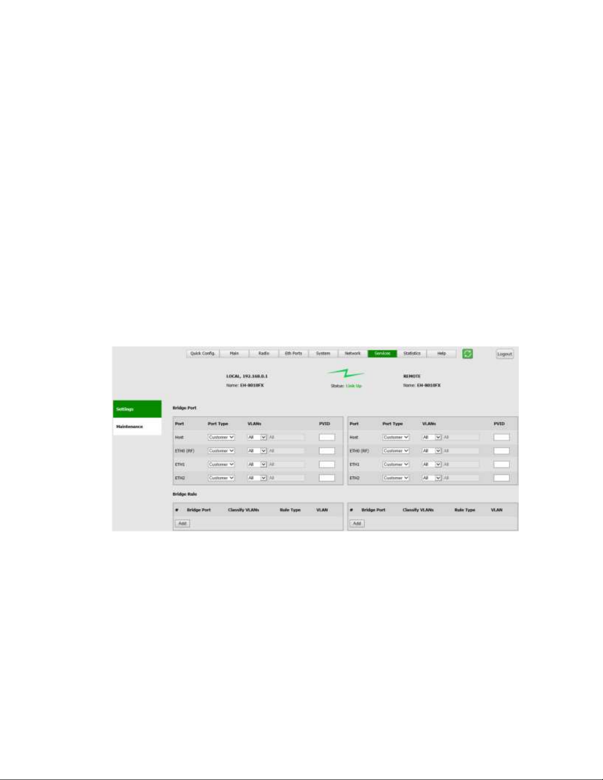
EtherHaul™ 8000 Installation, Operation and Maintenance Manual
Page 75
8 Ethernet Services Configuration and Monitoring
The Ethernet services (VLAN and bridge settings) parameters and monitoring are
provisioned in the Services page.
This chapter includes the following topics:
Bridge Architecture
Bridge Ports
Bridge Rules (Egress)
Maintenance
CLI Commands
Note that the following functionality, including S-VLAN support and Bridge Rules
support depends on product’s specs and SW release.
Refer to the products’s release notes for details.
Figure 8-1 Services Page: Settings
8.1 Bridge Architecture
The system incorporates a fully functional integrated Provider Bridge (IEEE 802.1ad).
Provider Bridge, commonly known as Q in Q, extends the IEEE 802.1Q standard by
providing for a second stack of VLANs in a bridged network. The general purpose of
Provider Bridge is to enable frames from multiple customers to be forwarded (or
tunneled) through another topology (provider network) using Service VLANs (S-VLAN).
Page 76
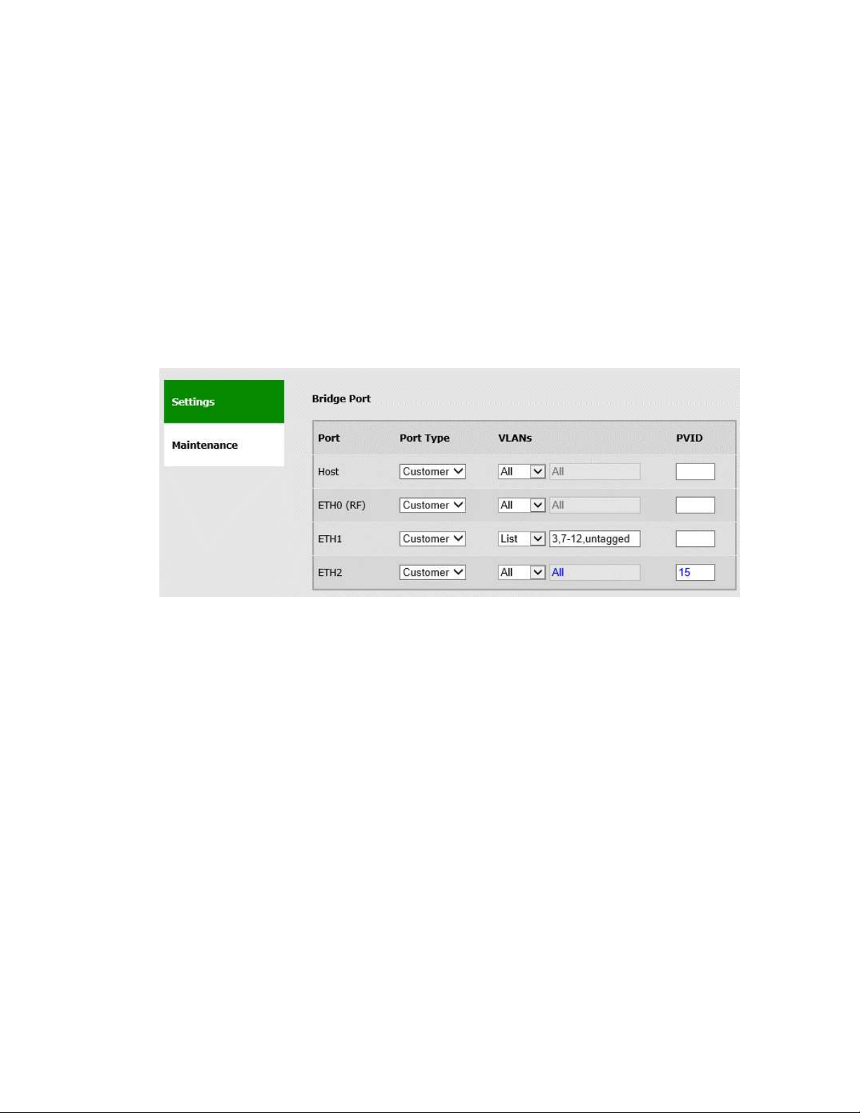
EtherHaul™ 8000 Installation, Operation and Maintenance Manual
Page 76
The provider bridge, which may consist of multiple devices in the service provider
domain, looks like a simple bridge port to the customer’s traffic and maintains the
Customer’s VLANs (C-VLAN).
The implementation of the bridge is a network of virtual bridges connected in a “crosslike” fashion. Each on of the ports acts as a virtual bridge and its type can be set
Customer (for C-VLANs) or Provider (for S-VLANs).
The default bridge architecture is transparent bridge, meaning all traffic will be
forwarded between all ports.
8.2 Bridge Ports
Figure 8-2 Bridge Ports Settings
Port:
The radio has the following bridge ports (corresponding to the system’s interfaces):
Host – Management interface (internal bridge port)
Eth0 – Radio (RF) interface (internal bridge port)
Eth1 – Line interface, 1GE port
Eth2 – Line interface, 10GE combo ports (refer to the active port of the two)
o RJ45 electrical (802.3an/bz)
o SFP+ optical (SM or MM)
Port Type:
Provider – port type that handles traffic tagged with S-VLANs.
Customer – port type that handles traffic tagged with C-VLANs. This is the
default port type of all the ports.
VLANs
Page 77
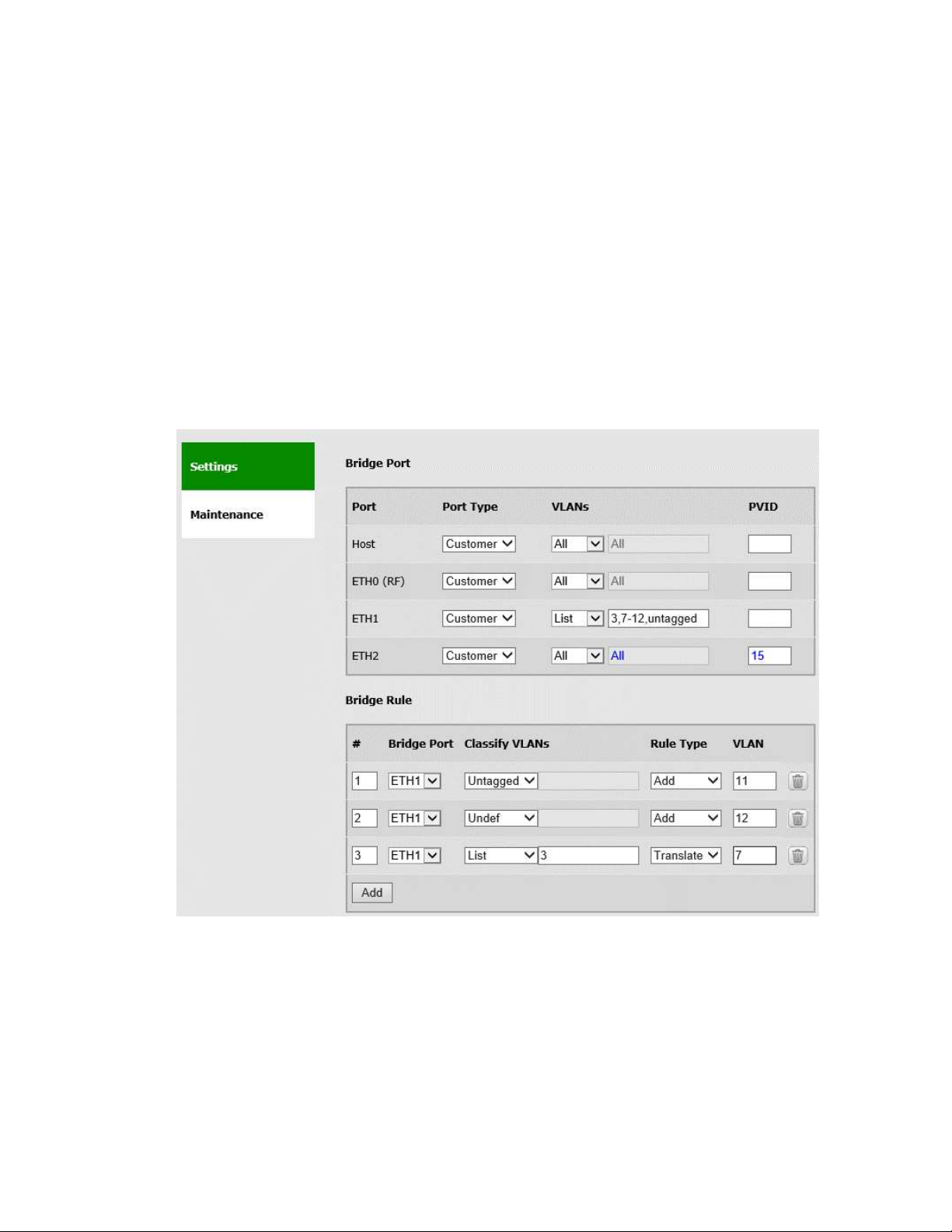
EtherHaul™ 8000 Installation, Operation and Maintenance Manual
Page 77
The bridge settings for ALL VLANs (tagged and untagged traffic) or List of specific VLANs.
Refers to C-VLANs when Port Type = Customer and to S-VLANs when Port Type =
Provider.
When selecting List, you may enter specific VLANs or range of VLANs separated by
comma. Enter ‘untagged’ if you want to allow untagged traffic on the port. All other
VLANs not specified will not be allowed on this port.
PVID
A VLAN ID which will be assigned to an untagged frame or a priority-tagged frame, (the
VID is set to 0 indicating that the frame does not belong to any VLAN and only PCP field
is relevant), which enters to the bridge through this port.
8.3 Bridge Rules
Figure 8-3 Bridge Rule
Bridge rules allow you to manipulate the egress VLAN settings for each port.
Rule Type = Add
A specific VLAN ID will be added to the received frame. Classify VLANs is used to add
different VLAN ID based on the received VLAN (C-VLANs only).
Page 78
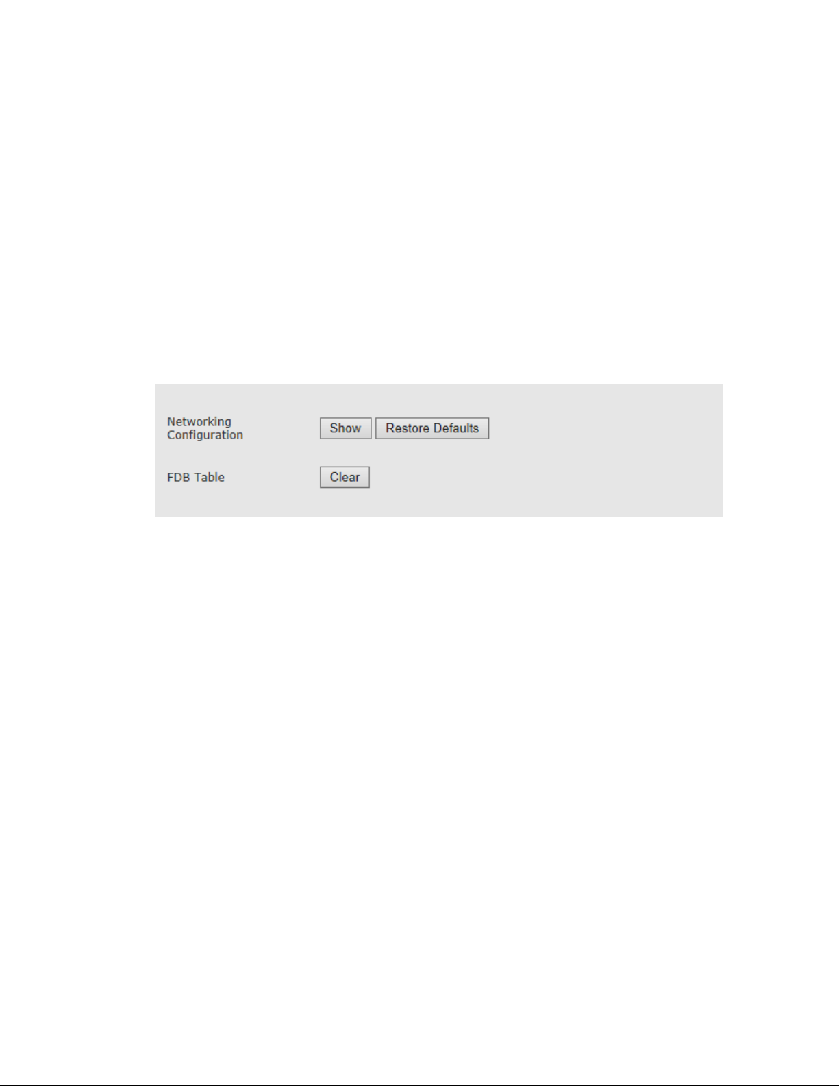
EtherHaul™ 8000 Installation, Operation and Maintenance Manual
Page 78
Classify VLAN options:
All – S-VLAN will be added on egrees to all received C-VLANs.
Untagged – VLAN will be added to untagged frames.
List – S-VLAN will be added to all listed C-VLANs.
Undef – S-VLAN will be added to all C-VLANs that do not have a specifc
bridge rule.
Rule Type = Translate
Allows stranslating specific VLAN or list of VLANs and replacing them with another
VLAN.
8.4 Maintenance
Figure 8-4 Services Page: Maintenance
In the Networking Configuration click Show to view (pop-up screen) the full networking
services configuration in the form of CLI commands.
Click Restore to restore factory default networking services settings. The system will
restore factory default networking services settings.
In the FDB Table click Clear to clear all MAC entries in the Forwarding Database table.
MAC are stored in unique FDB table per per C-VLAN.
Page 79

EtherHaul™ 8000 Installation, Operation and Maintenance Manual
Page 79
8.5 CLI Commands
Bridge Port:
Bridge port options:
show bridge-port
show bridge-port [<bridge-port> [<modifier>]]
<bridge-port> : all | host | eth0 | eth1 | eth2
<modifier> : info | port-type | vlans-list | pvid
Viewing bridge ports:
show bridge-port
Bridge Rule:
Bridge rule options:
show bridge-rule ?
show bridge-rule [<bridge-port-list> [<rule-id> [<modifier>]]]
<bridge-port-list> : all | list: | host | eth0 | eth1 | eth2
<rule-id> : all | integer 1..100
<modifier> : info | classify-vlans | rule-type | vlan
Viewing bridge rules:
show bridge-rule
Page 80

EtherHaul™ 8000 Installation, Operation and Maintenance Manual
Page 80
9 Administration
This chapter describes the system's administration capabilities and procedures and
includes the following topics:
Users Administration
SNMPv3 Users Configuration
Zero-Touch Configuration
Monitoring CLI Login Sessions
DHCP Relay (Option 82)
9.1 TACACS+/RADIUS Users Administration
The system supports both internal user management and external Radius or TACACS
server.
To administrate users, refer to the Users Administration section in the Network Page.
The page will be updated based on the selected Authentication Mode.
For internal user management (standard user/passwords that are configured in the
device), select Local as the Authentication Mode.
Local users administration (default mode) is described in the to the Users Administration
section under Network Configuration and Monitoring chapter of this manual.
9.1.1 AAA Description
RADIUS (Remote Authentication Dial-In User Service) and TACACS+ (Terminal Access
Controller Access-Control System) are AAA mechanisms.
Authentication: Identification of requester profile (username, password, and
privilege level) on a per-request basis.
Authorization: Permission/denial of access to a subset of commands subject to
authentication success/failure. (The mechanisms of Authorization and
authentication are independent of each other.)
Accounting: Reporting of information on requesters (identities, number of
access attempts per requester, start and stop times, executed commands, etc.)
The system is a Network Access Server (NAS) for requesters and functions as AAA client
passing requester information (e.g. username, password, etc.). The AAA Server is
responsible for receiving connection requests, authenticating or disqualifying the
requester, and sending the permit or denies response to the client. Communication
between the system and the AAA Server are permitted by shared secrets which are
never sent over the network. In addition, every administrator password is encrypte d
Page 81
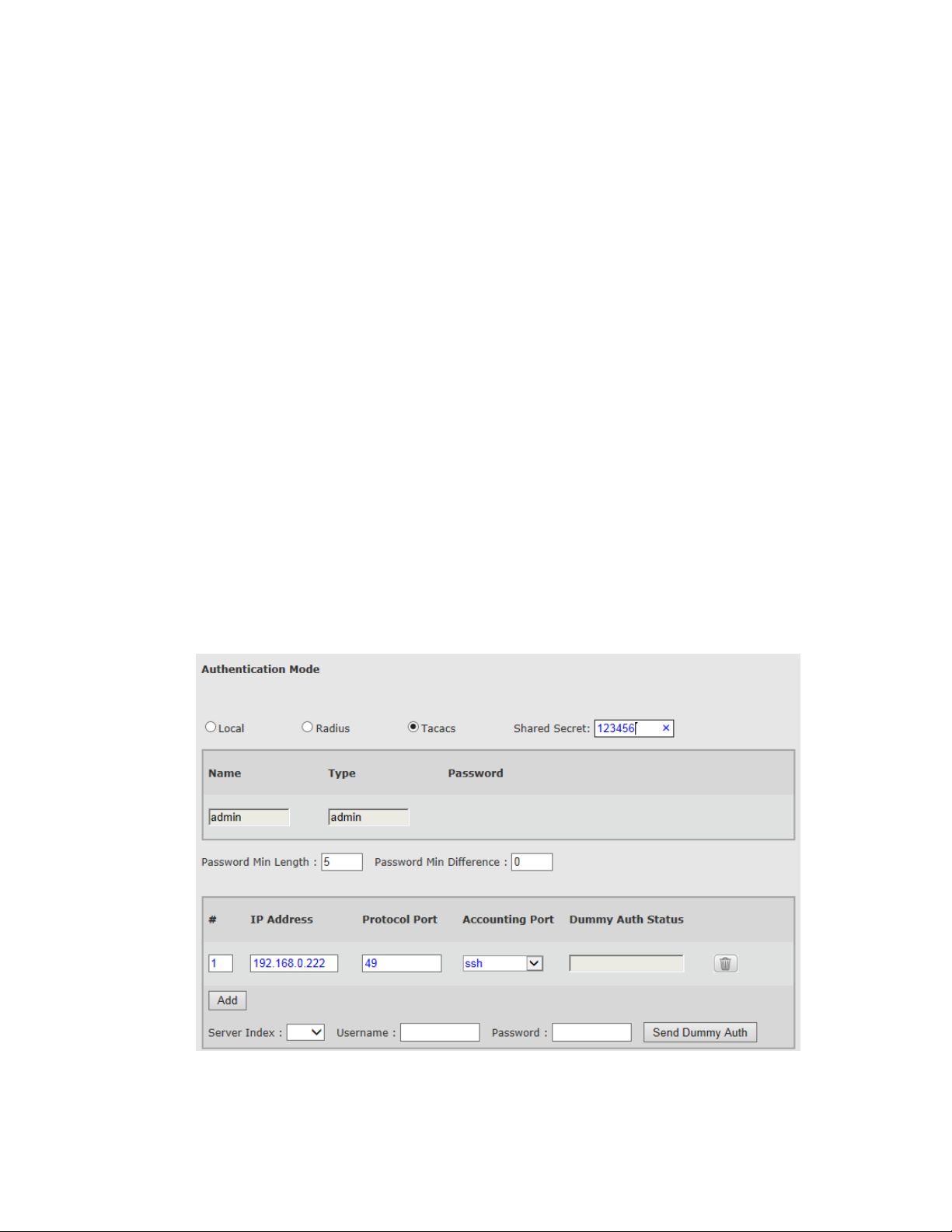
EtherHaul™ 8000 Installation, Operation and Maintenance Manual
Page 81
before it is sent between the system and the AAA Server in order to prevent
deciphering.
The AAA Server can also provide accounting of requester commands and of changes in
authorization level. This information is recorded in a special log file that enabl es a
supervisor to view the activities of all the administrators. Accounting can include logging
of commands or logging of transitions from one mode to another.
The system supports authentication with up to five TACACS+ or Radius AAA servers.
9.1.2 Authentication Modes
Three Authentication modes supported:
Local – Users configured in system, including name, password and type.
Tacacs – Users configured in the AAA Tacacs server. Only Admin user configured
in system.
Radius – Users configured in the AAA Radius server. Only Admin user configured
in system.
Every change in the Auth-mode deletes all users (except for the admin user) and
configured servers.
Communication between the system and the AAA servers is done over shares secret.
9.1.3 TACACS Authentication Mode
Figure 9-1 Network Page: Users Administration – TACACS
Page 82

EtherHaul™ 8000 Installation, Operation and Maintenance Manual
Page 82
Only admin user is defined in the system. All other users (including their name,
password and type) are defined in the server.
Note that local admin access will always be available (regardless of the connectivity to
the AAA server).
This section allows configuring the following parameters:
Authentication Mode – Tacacs.
Shared Secret – In Radius or Tacacs mode, Shared Secret should be entered
(identical to the one in the server). Note that is using more than one AAA server,
the servers should have the same Shared Secret.
# - Server index. Up to 5 servers can be configured. The Authentication starts
from the 1st server and goes down to the 5th.
IP Address – of the AAA server.
Protocol Port – the default port for Tacacs is 49.
Accounting Port – none, SSH, HTTP, all.
Dummy Authentication is used for sanity check (connectivity test) to the AAA server.
If the AAA server has Dummy user define, select the Server Index and enter the
username and password. After clicking Send Dummy Auth, you will be able to see the
reply status in the Dummy Auth Status field.
Dummy Authentication is supported for Tacacs only.
Page 83
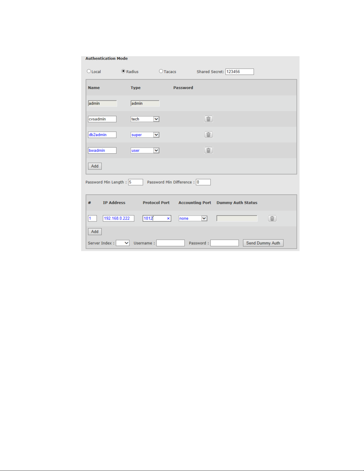
EtherHaul™ 8000 Installation, Operation and Maintenance Manual
Page 83
9.1.4 Radius Authentication Mode
Figure 9-2 Network Page: Users Administration – Radius
Only admin user is defined in the system. All other users (including their name,
password and type) are defined in the server.
Note that local admin access will always be available (regardless of the connectivity to
the AAA server).
This section allows configuring the following parameters:
Authentication Mode – Radius.
Shared Secret – In Radius or Tacacs mode, Shared Secret should be entered
(identical to the one in the server). Note that is using more than one AAA server,
the servers should have the same Shared Secret.
# - Server index. Up to 5 servers can be configured. The Authentication starts
from the 1st server and goes down to the 5th.
IP Address – of the AAA server.
Protocol Port – the default port for Radius is 1812.
Accounting Port – none, SSH, HTTP, all.
Page 84

EtherHaul™ 8000 Installation, Operation and Maintenance Manual
Page 84
Dummy Authentication is not supported for Radius (Tacacs only).
Working with Radius
Add the following lines to your Radius dictionary:
When adding users to the SKL_USERGROUP and assigning them type, use ‘_’before the
type:
9.2 CLI Commands
Users:
Viewing users list:
show user
Tacacs:
Viewing authentication:
show aaa
Configuring Tacacs authentication:
set aaa mode tacacs shared-secret 123456
Viewing servers:
show aaa-server
Configuring Tacacs server:
set aaa-server 1 ip-addr 192.168.0.22 port 49 accounting-port ssh
Sending Dummy Authentication request :
set aaa-server 1 send-dummy-auth username dummy1 password pass1
Viewing Dummy Authentication status:
show aaa-server
Radius:
Viewing authentication:
show aaa
Configuring Radius authentication:
set aaa mode radius shared-secret 123456
Viewing servers:
show aaa-server
###### SKL Additions ######
ATTRIBUTE SKL_USERGROUP 170 string
User with ‘admin’ type:
SKL_USERGROUP = "SKL_USERGROUP=_admin"
User with‘super’ type:
SKL_USERGROUP = "SKL_USERGROUP=_super"
Page 85
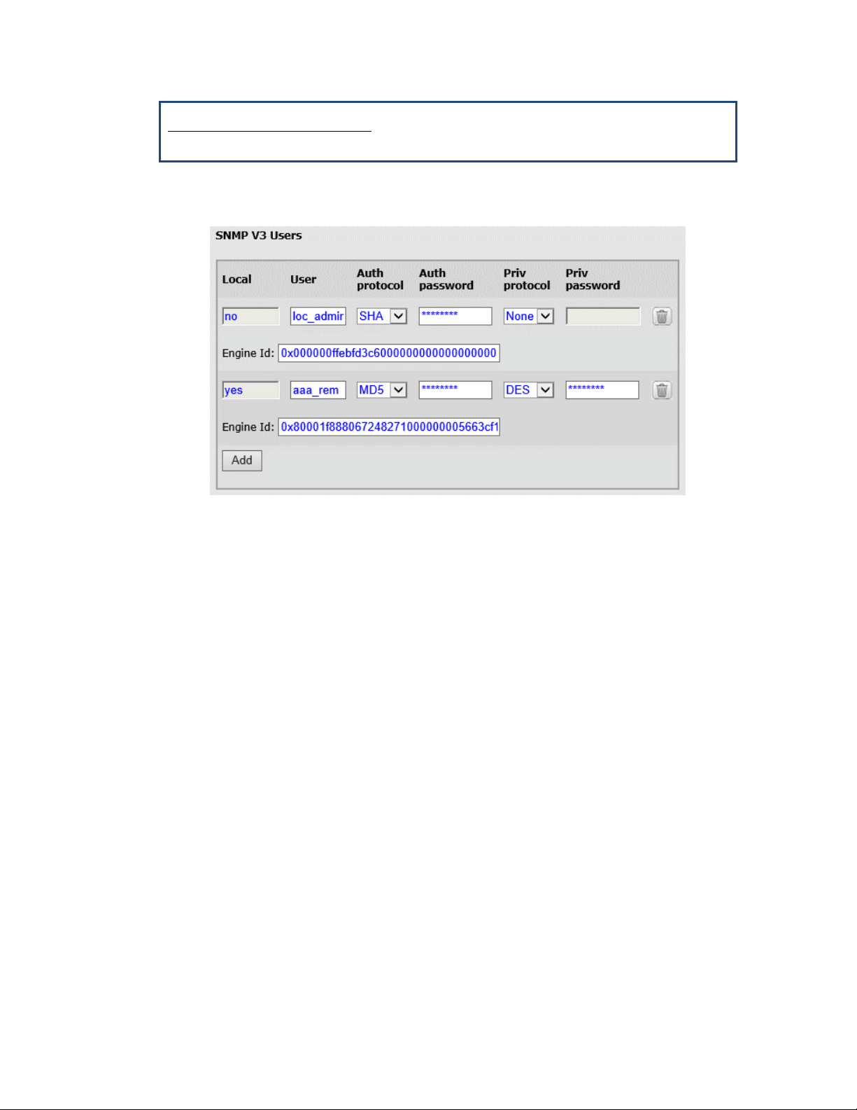
EtherHaul™ 8000 Installation, Operation and Maintenance Manual
Page 85
Configuring Tacacs server:
set aaa-server 1 ip-addr 192.168.0.22 port 1812 accounting-port ssh
9.3 SNMPv3 Users Configuration
Figure 9-3 Network Page: Advanced Settings – SNMP V3 Users
This section allows setting the SNMP V3 users.
CLI settings:
set snmp-user <engine-id> <user> <auth> <priv>
<engine-id> : | local | string
<auth> : none | {md5 <passphrase>} | {sha
<passphrase>}
<priv> : none | {des <passphrase>} | {aes
<passphrase>}
auth-passphrase and privacy-passphrase are ASCII strings. Together with internally
calculated Engine ID these strings are used to produce authentication and privacy keys
respectively.
If no parameters other than the user name are supplied to the set command, an entry is
created for the user identified by the name while privacy and authentication algorithms
are set to NULL.
If a privacy algorithm (des or aes) is not supplied, the privacy algorithm is set to NULL.
If a privacy-passphrase is not supplied, the privacy-passphrase is the same as the
authentication passphrase.
Page 86

EtherHaul™ 8000 Installation, Operation and Maintenance Manual
Page 86
SNMP Managers
Each SNMPv3 agent has an engine ID that uniquely identifies the agent in the device and
also the unique identification of the MIB objects within a domain.
In SNMPv3 communication, Engine ID is used as an identifier for an agent among other
agents.
When you define get and set commands for SNMPv3 user, set Engine ID to Local. When
you define trap for SNMPv3 user, set Engine ID to the value of the Engine ID of the
remote manager.
Note that get, set, and trap commands should be defined for the same user. The same
user should be defined twice: once with Engine ID=Local and the second time with the
Engine ID of the remote manager.
9.4 Monitoring CLI Sessions
Use the following command to display active CLI sessions:
show loginsession [{my | all}]
In response, the software displays the following:
Session ID Session Time
xx dddd:hh:mm:ss
yy dddd:hh:mm:ss
Where:
xx or yy is a two-digit integer from 00 to 99, and
dddd:hh:mm:ss – days(0000 – 9999):hours(00 – 24):minutes(00 – 60):seconds(00 – 60)
To display only the CLI session of the user entering the command, use the show
loginsession my command.
To display all active CLI session, use the show loginsession all command.
The maximum number of CLI sessions is 10.
Note:
Monitoring CLI login sessions supported in the CLI only.
Page 87

EtherHaul™ 8000 Installation, Operation and Maintenance Manual
Page 87
10 Diagnostics
The system features a wide range of built-in indicators and diagnostic tools designed to
enable you to quickly evaluate a link’s performance, identify operating faults, and
resolve them.
The general diagnostics process for a radio link is to identify whether there is a problem
that needs to be addressed, to isolate the root cause of the problem, and to implement
the steps that are required to solve the problem.
The following is a partial list of events that can cause system problems:
End equipment problems (such as connection or device configuration issues)
External hardware faults
System level configuration issues
Hardware faults that require radio link replacement
This chapter describes the system’s diagnostics features, and offers basic instructions
for how to use these features to isolate and resolve operating faults in the ODUs or in
the a network. The chapter includes the following topics:
Troubleshooting Process
System LEDs
Alarms
Performance Statistics
Loopbacks
10.1 Troubleshooting Process
Follow this step-by-step process whenever you encounter a problem with the link.
Step 1: Define the Problem
Isolating a problem’s symptoms is the first step in corrective maintenance. It is
important to define the problem clearly and fully.
Define the problem as either a customer-impact type (for example, loss of element
management, or no Ethernet services over the link) or a product-related type (for
example, a link is down or an ODU does not power up).
Step 2: Check and Gather Relevant Information
Examining the link’s status indications will provide both current and historical
information regarding the link’s performance and alarms.
Indications include ODU LEDs, System Alarms, and System Statistics.
Use these indications to further refine the problem and help to assess possible causes,
both physical and logical, in the system.
Page 88

EtherHaul™ 8000 Installation, Operation and Maintenance Manual
Page 88
Step 3: Isolate the Fault
Further isolate and characterize the problem using all available link indications.
Ascertain if the problem is related to:
End-equipment configuration or an interconnection
A hardware fault in the link’s accessories (such as a cable)
Configuration settings (this can be verified using the CLI)
A hardware fault in one of the ODUs
A result of larger network propagation problem
Note that Loopback indications are especially useful when isolating the fault’s
component and network location.
Step 4: Correct the Fault
Once the fault is isolated, implement the necessary corrective actions until resolution of
the problem is confirmed.
Whenever possible, it is recommended that you repeat commissioning tests in order to
verify that the problem link is now operating correctly.
Step 5: Need Support?
Contact us for technical support in case assistance is needed.
Include detailed description of the issue and what steps were taken trying to solve it.
Send the output of the System_info script from both sides (copy its output to a text file)
for efficient service.
The script collects all the relevant system status, logs, configurations and statistics.
10.2 System LEDs
LED
Color
Description
PWR (Power)
Green – Power OK
Blink Green – Device boot (~90 sec)
Red – Power Failure
Off – Radio off
RF
Green – Link Up
Orange – Alignment Mode
Off – Link Down
1G port:
Green – Link (Carrier) 1G
Blink Green – 1G activity
Orange – Link (Carrier) 10/100M
Blink Orange – 10/100M activity
Off – No Link (Carrier)
10G ports:
Green – Link (Carrier) 10G
Blink Green – 10G activity
Page 89

EtherHaul™ 8000 Installation, Operation and Maintenance Manual
Page 89
LED
Color
Description
Orange – Link (Carrier) 10/100/1G/2.5G/5G (RJ45 only)
Blink Orange – 10/100/1G/2.5G/5G activity
Off – No Link (Carrier)
10.3 Alarms
System alarms can be found on the Main Page, including:
Current Alarms – list of currently active alarms and date+time raised.
History Log – System alarms and events history log
Event Name
Description
Probable Cause
Corrective Actions
Cold start: the first
time wake up
System power up
after power
connection
1) Restoring the power
2) Reset caused by power
disruption
Power restored, no corrective
actions needed
Cold start: software
initiated reset
System power up
after userinitiated software
reset
1) User action: reset
system
2) User action: rollback
timeout expired
3) User action: SW
upgrade
Power restored after user
action, no corrective actions
needed
Cold start: reset
button has been
pushed for less
than 5 sec
System power up
after user pressed
the reset button
(for less than 5
seconds)
1) User action: reset
button pressed for less
than 5 seconds causing a
reset
Power restored after user
action, no corrective actions
needed
Cold start: reset
button has been
pushed for more
than 5 sec
System power up
after user pressed
the reset button
(for more than 5
seconds),
restoring factory
defaults
1) User action: reset
button pressed for more
than 5 seconds causing
factory defaults restore
Power restored after user
action, no corrective actions
needed
Cold start: power
failure reset
System power up
after system reset
due to power or
internal failure
1) Restoring the power
2) Reset caused by power
disruption or internal
power failure
Power restored, no corrective
actions needed.
If repeated and no indication
for power disconnection, might
indicate system failure and ODU
should be replaced.
Cold start: hardware
watchdog reset
System power up
internal HW
watchdog reset,
indication system
fault
System failure
Replace ODU
Page 90

EtherHaul™ 8000 Installation, Operation and Maintenance Manual
Page 90
Cold start: the
hardware watchdog
has not been
activated in time
Internal HW
watchdog failure,
indicating system
fault
System failure
Replace ODU
Cold start: software
watchdog reset
System power up
internal SW
watchdog reset,
indication system
fault
System failure
Replace ODU
Link down
Link down
(operational
down) on one of
the Ethernet
interfaces
Line interfaces
(eth1,eth2,eth3,eth4):
1) Ethernet cable
disconnected or not
connected properly.
2) Ethernet interface
disabled (admin down).
3) Port settings mismatch
4) Interface HW fault.
Radio interface (eth0):
1) Low receive signal (due
to antenna mis-alignment
or rain fading).
2) Mismatch in rf
configuration between
sides or wrong
configuration.
3) Interference.
4) HW fault.
Line interfaces
(eth1,eth2,eth3,eth4):
1) Verify cable terminated and
connected properly.
2) Verify port configuration,
including auto-neg and
speed/duplex.
3) Replace ODU.
Radio interface (eth0):
1) Improve antenna alignment
and verify clear line of sight.
2) Verify RF configuration.
3) Change channel to verify no
interference.
4) Replace ODU.
Link Up
Link up
(operational up
on one of the
Ethernet
interfaces
Link down state cleared
and interface is up
(operational).
Link restored, no corrective
actions needed.
Modulation Change
RF link
modulation
changed to the
specified
modulation
profile
In adaptive mode:
Modulation changed (up
or down) due to change in
link RF link conditions.
In static mode:
Modulation changed
manually or when link
changed state to up or
down.
Verify if modulation change is
due to rain fading, misalignment or interference.
1) Improve antenna alignment
and verify clear line of sight.
2) Verify RF configuration.
3) Change channel to verify no
interference.
4) Replace ODU.
Temperature High
Extreme
temperature
condition (unit
temperature is
Extreme temperature
condition.
1) Verify air-flow not
obstructed.
2) Verify ODU is installed in
Page 91

EtherHaul™ 8000 Installation, Operation and Maintenance Manual
Page 91
too high or too
low, exceeding
the configurable
thresholds)
temperature range according to
specs.
Temperature
Normal
Unit temperature
returned to
normal
The unit temperature
condition returned to
normal.
Temperature returned to
normal, no corrective actions
needed.
SFP In
SFP inserted to
one of the Line
Ethernet ports
User action: SFP was
inserted.
User action: No corrective
actions needed.
SFP Out
SFP extracted
from one of the
Line Ethernet
ports
User action: SFP was
extracted.
User action: No corrective
actions needed.
Loop Enabled
Loopback was
enabled on one of
the Ethernet
interfaces
User action: Loopback
enabled.
User action: No corrective
actions needed.
Loop Disabled
Loopback was
disabled on one of
the Ethernet
interfaces
1) Loopback cleared as
loopback timeout expired.
2) User action: Loopback
disabled.
User action: No corrective
actions needed.
Tx Mute Enabled
Tx mute enabled
(ODU will not
transmit on its
radio interface)
User action: ODU muted.
User action: No corrective
actions needed.
Tx Mute Disabled
Tx mute disabled
(ODU will resume
transmitting on its
radio interface)
1) Tx mute cleared as Tx
mute timeout expired.
2) User action: Tx mute
disabled.
User action: No corrective
actions needed.
Lowest Modulation
System dropped
to lowest
modulation
profile configured
(in Adaptive
Mode).
Modulation changed
(down to lowest
configured threshold) due
to change in RF link
conditions.
Verify if modulation change is
due to rain fading, misalignment or interference.
1) Improve antenna alignment
and verify clear line of sight.
2) Verify RF configuration.
3) Change channel to verify no
interference.
4) Replace ODU.
Rate Changed
Eth port rate
changed
Rate changed due to port
down (normal in case of
port disconnected or
reboot) or negotiation
failure
If Eth port rate is lower than
expected:
1) Check port settings and autoneg settings.
2) Check cables (bad
cable/crimpting of RJ45 will not
allow port to go to highest rate.
3) Replace ODU.
Page 92
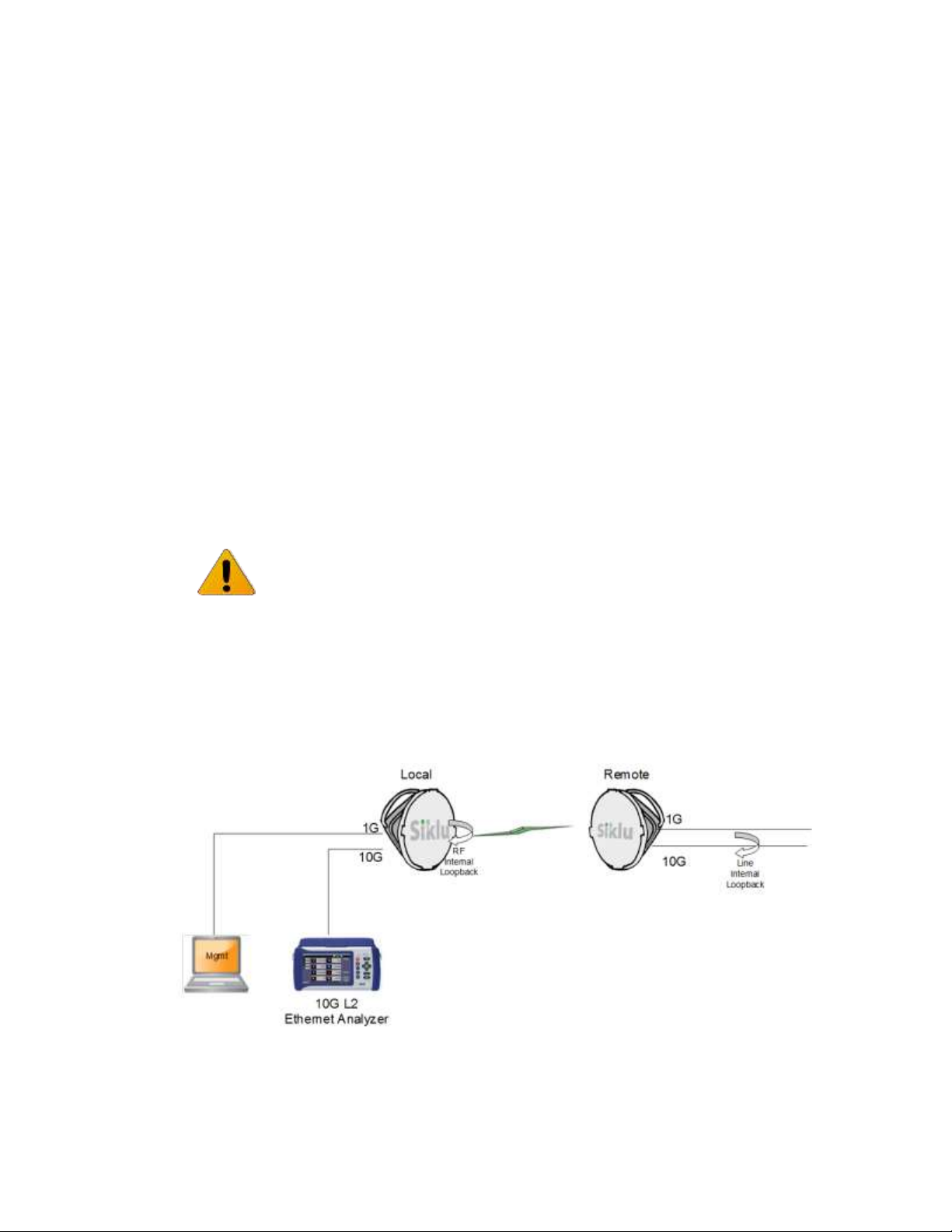
EtherHaul™ 8000 Installation, Operation and Maintenance Manual
Page 92
10.4 Performance Statistics
The system uses advanced RF and Ethernet counters to provide real-time performance
statistics for radio transmission activities and Ethernet ports/services.
Refer to the Statistics chapter of this manual for detailed description of the
performance monitoring statistics.
10.5 Loopbacks
The system uses Ethernet and RF loopbacks designed to enable fault isolation and
Ethernet service performance testing.
Ethernet Line Loopback – Internal loopback is performed on the interface,
testing the local system, the radio link, and the remote system.
RF (Radio) Loopback – Internal loopback is performed on the system’s RF
output.
Note:
After activating Loopback, it is important to clear all RF and Ethernet statistics in
order to receive the most accurate results for analysis.
Use system alarms as well as statistic displays to determine if Loopback testing has
passed or failed.
Loopbacks can be applied with a timeout (up to 24 hours). When timeout expires, the
loopback will be removed.
10.5.1 Loopbacks Diagram
Figure 10-1 System Loopback Points
Page 93
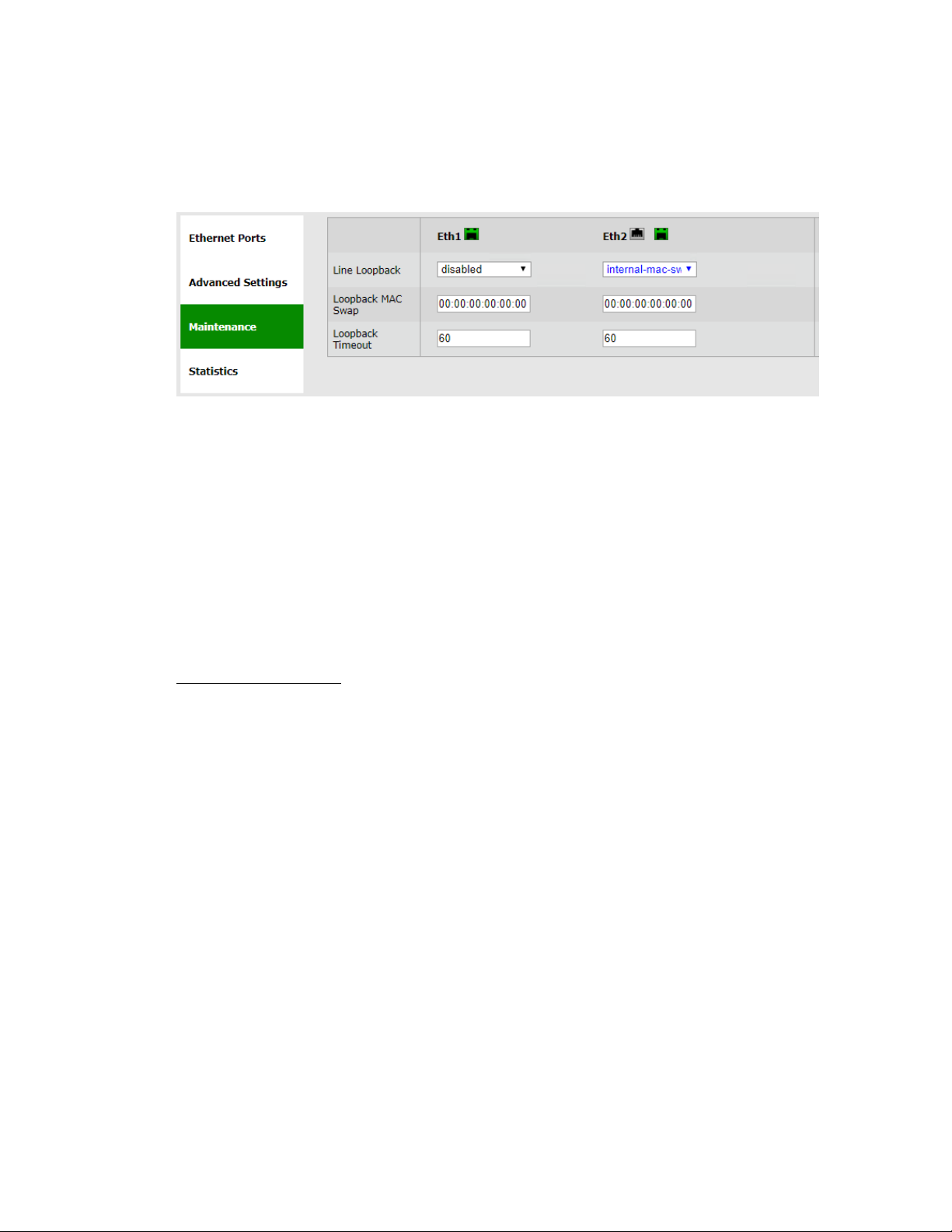
EtherHaul™ 8000 Installation, Operation and Maintenance Manual
Page 93
10.5.2 Ethernet Line Loopbacks
The loopback can be applied separately for each one of the interfaces.
Ethernet loopbacks can be set in the Maintenance section of the Eth Ports page.
Figure 10-2 Ethernet Line Loopback
This section allows configuring the following parameters:
Line Loopback – checkbox to enable loopback on the port. Internal (towards the
radio side) loopback is available, with specific MAC addresses swap.
Loopback MAC Swap – Loopback is performed with MAC addresses swap
(swapping DA and SA) for the address specified only. All other MAC addresses
not looped.
Loopback Timeout – in seconds. Loopback will clear when timeout expires (up to
24 hours, 0= no timeout).
Internal Line Loopback
An Internal loop returns the received frames to the radio side, enabling you to test
Ethernet traffic across the link.
The Ethernet traffic from the Customer’s end-equipment or Ethernet analyzer is looped
at the Ethernet interface of the remote system, enabling testing of the connection
(cable/fiber), the interface between end-equipment and the local system, both local and
remote systems and the radio transmission.
10.5.3 Radio (RF) Loopback
The Ethernet traffic from a customer’s end-equipment or Ethernet analyzer is looped on
the system’s radio output, enabling testing of the connection (cable/fiber), the interface
between the system and end-equipment and the local system.
The loopback is set with MAC Address swapping for the specified MAC address on
specific modulation profile set by the user.
Page 94
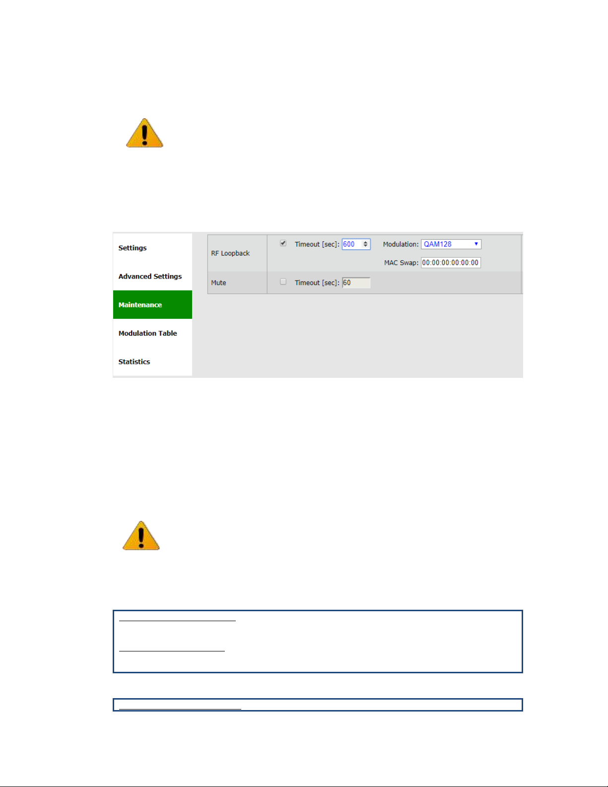
EtherHaul™ 8000 Installation, Operation and Maintenance Manual
Page 94
Note:
For error-free operation at high modulation profiles, no interference should be
present. Switch off or mute remote system before applying the RF loopback.
Alternatively, change remote frequency to eliminate risk of interference.
It will take the system to stabilize after loopback about 3 minutes before checking
radio performance using the alarms and statistics.
Enable the loopback and set the loopback-timeout in seconds (up to 24 hours, 0= no
timeout, recommended minimum of 600 seconds).
RF loopback can be set in the Maintenance section of the Radio page.
Figure 10-3 RF Loopback
This section allows configuring the following parameters:
RF Loopback – checkbox to enable the internal RF loopback, set the timeout for
clearing the loopback in seconds and select the modulation the ODU will be
tested at.
10.5.4 CLI Commands
Loopback timeout:
Line loopback timeout
set eth eth1 loopback-timeout 600
RF loopback timeout
set rf loopback-timeout 600
Activating Ethernet loopback:
Line internal loopback
Note:
Loopback is performed with MAC addresses swap (swapping DA and SA) for the
address specified only. All other MAC addresses not looped.
Page 95

EtherHaul™ 8000 Installation, Operation and Maintenance Manual
Page 95
set eth eth2 loopback-mode internal-mac-swap loopback-dst-mac
AA:BB:CC:AA:BB:CC
RF loopback
set rf loopback internal-mac-swap qam128
Clearing loopback:
Line loopback
set eth eth1 loopback-mode disabled
RF loopback timeout
set rf loopback disabled
Page 96
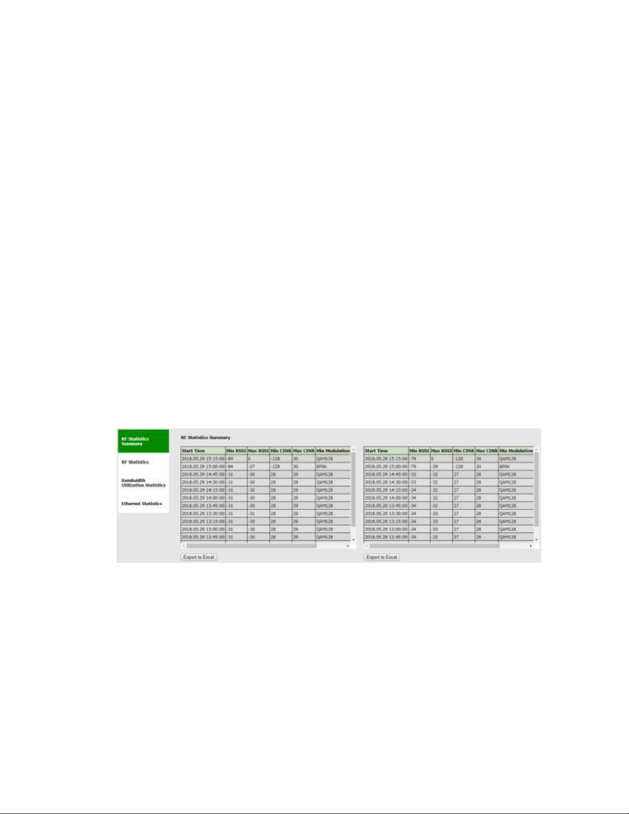
EtherHaul™ 8000 Installation, Operation and Maintenance Manual
Page 96
11 Statistics
The system uses advanced RF and Ethernet counters to provide real-time performance
statistics for radio transmission and Ethernet ports.
The following statistics enable quick analysis of system and component performance in
support of troubleshooting and diagnostics.
RF statistics – displays RF statistic counters to identify radio errors and check the
radio status history. The RF statistics consist of real time statistic counters since
the last time the counters were cleared
Ethernet statistics - displays Ethernet statistics counters per Ethernet port
This chapter describes the system's statistics.
The statistics are presented in the dedicated Statistics page.
Statistics can be exported to Excel by clicking the Export to Excel button next to
the relevant table.
11.1 Radio (RF) Statistics Monitoring
11.1.1 RF Statistics Summary
Summary of radio statistics – 96 intervals of 15 minutes (last 24 hours), recording the
minimum and maximum values per interval of RSSI, CINR and Modulation profile.
Figure 11-1 Statistics Page: RF Statistics Summary
RF Statistics Summary is cleared upon system reboot.
Page 97
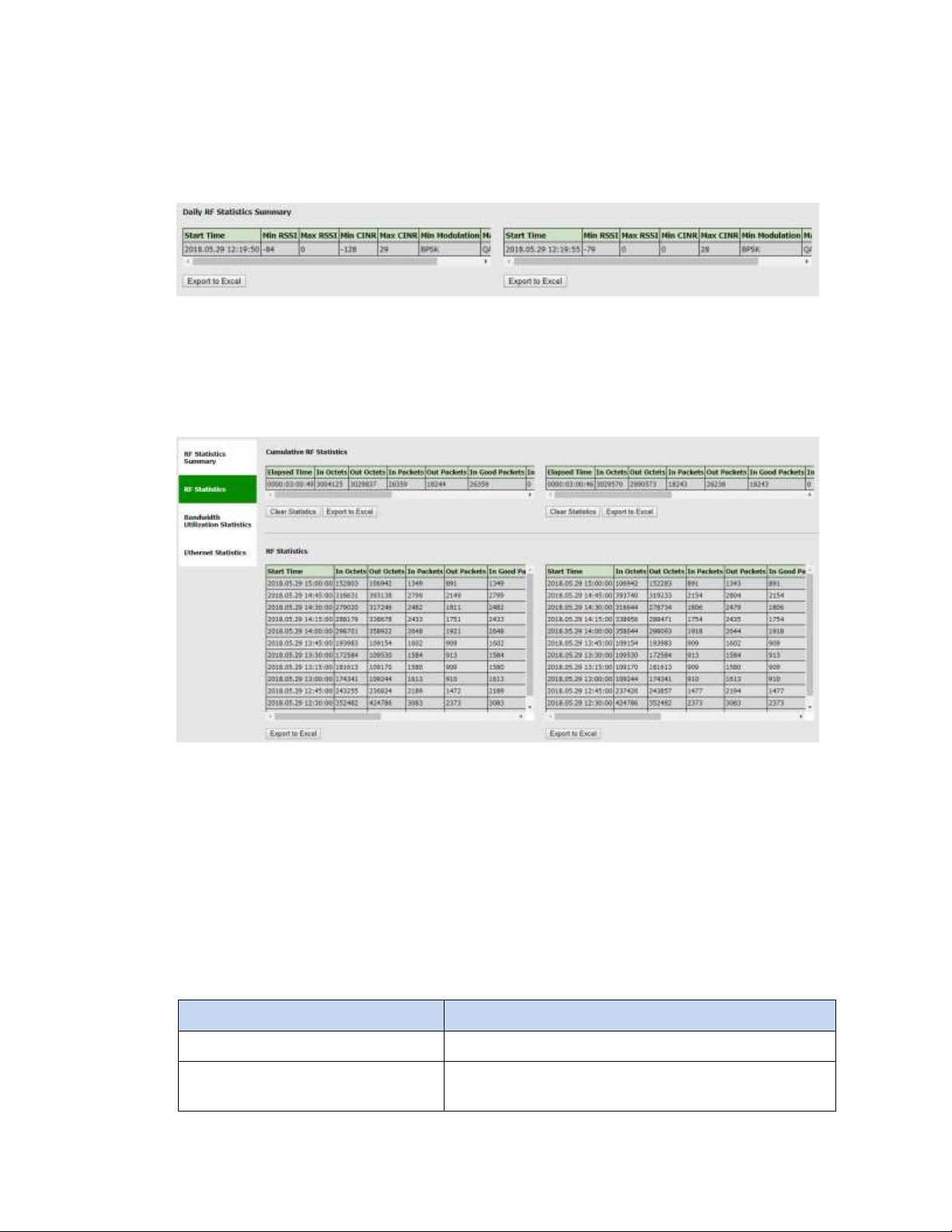
EtherHaul™ 8000 Installation, Operation and Maintenance Manual
Page 97
11.1.2 RF Statistics Summary – 30 days
Summary of radio statistics – 30 intervals of 24 hours, recording the minimum and
maximum values per interval of RSSI, CINR and Modulation profile.
Figure 11-2 Statistics Page: RF Statistics Summary – 30 days
RF Statistics Summary is cleared upon system reboot.
11.1.3 RF Statistics
Figure 11-3 Statistics Page: RF Statistics
Check RF statistic counters to identify radio errors and check the radio status history.
The RF statistics consist of real time statistic counters since the last time the counters
were cleared.
The RF transmission quality indicators are rf in-errored-pkts and rf-in-
errored-octets. If incremented, these parameters indicate radio errors. No errors
in these indicators indicate that the radio link is operating without errors.
Radio statistics counters – recording 96 intervals of 15 minutes (last 24 hours) of the
following parameters:
Attribute
Description
Incoming Octets (in-octets)
The total number of octets received from the RF link.
Incoming Idle Octets
(in-idle-octets)
The total number of octets received from the RF link
while idle.
Page 98

EtherHaul™ 8000 Installation, Operation and Maintenance Manual
Page 98
Attribute
Description
Incoming Good Octets
(in-good-octets)
The number of good octets received from the RF link.
Incoming Erroneous Octets (inerrored-octets)
The number of received erred octets from the RF link.
Outgoing Octets (out-octets)
The total number of octets transmitted to the RF link.
Outgoing Idle Octets
(out-idle-octets)
The total number of octets transmitted to the RF link
while idle.
Incoming Packets (in-pkts)
The total number of packets received from the RF link.
Incoming Good Packets (in-goodpkts)
The total number of good packets received from the RF
link.
Incoming Erroneous Packets (inerrored-pkts)
The total number of erred packets received from the RF
link.
Outgoing Packets (out-pkts)
The total number of packets transmitted to the RF link.
Minimum CINR value (min-cinr)
The minimal CINR value recorded in the interval.
Maximum CINR value (max-cinr)
The maximal CINR value recorded in the interval.
Minimum RSSI value (min-rssi)
The minimal RSSI value recorded in the interval.
Maximum RSSI value (max-rssi)
The maximal RSSI value recorded in the interval.
Minimum modulation value (minmodulation)
The lowest modulation profile recorded in the interval.
Maximum modulation value (maxmodulation)
The highest modulation profile recorded in the interval.
11.2 Bandwidth Utilization Statistics
Presented per port: Eth0 (RF), Eth1 (1GE) and Eth2 (10GE active) – 96 intervals of 15
minutes (last 24 hours).
Page 99
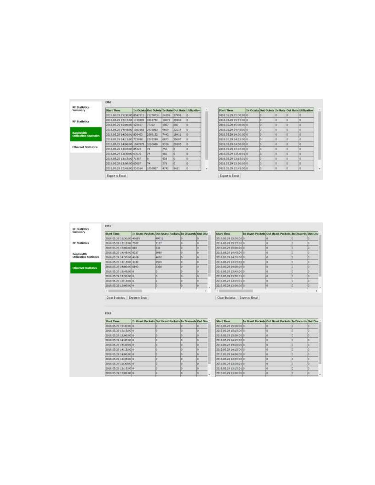
EtherHaul™ 8000 Installation, Operation and Maintenance Manual
Page 99
The total in-octets, out-octets, in-rate, out-rate and
utilization (aggregated, meaning Tx and Rx) are displayed.
For Eth0 (RF), bandwidth utilization is displayed as percentage of the aggregated (total
Tx and Rx) max radio rate per the current modulation.
The rates displayed are averaged over the 15 minutes intervals.
Figure 11-4 Statistics Page: Bandwidth Utilization Statistics
11.3 Ethernet Statistics
Figure 11-5 Statistics Page: Ethernet Statistics
Presented per port: Eth0 (RF interface of the bridge), Eth1 (1GE) and Eth2 (10GE active
port) – 96 intervals of 15 minutes (last 24 hours).
Page 100

EtherHaul™ 8000 Installation, Operation and Maintenance Manual
Page 100
Radio statistics counters – recording 96 intervals of 15 minutes (last 24 hours) recording
the following parameters:
Attribute
Description
Incoming Octets (in-octets)
The total number of octets received on the interface,
including framing characters.
Incoming Unicast Packets (in-ucastpkts)
The number of unicast packets received on the
interface.
Discarded Incoming Packets (indiscards)
The number of packets which were chosen to be
discarded due to RX FIFO full.
Erroneous Incoming Packets (inerrors)
The number of received erred packets.
Outgoing Octets (out-octets)
The total number of octets transmitted out of the
interface, including framing characters.
Outgoing Unicast Packets (out-ucastpkts)
The number of unicast packets transmitted out of the
interface.
Discarded Outgoing Packets (outdiscards)
The number of outbound packets that were chosen to
be discarded due to excessive collision or excessive
deferral.
Erroneous Outgoing Packets (outerrors)
The number of outbound packets that could not be
transmitted because of errors.
Incoming Multicast Packets (inmcast-pkts)
The number of multicast packets received on the
interface.
Incoming Broadcast Packets (inbcast-pkts)
The number of broadcast packets received on the
interface.
Outgoing Multicast Packets (outmcast-pkts)
The number of multicast packets transmitted out of the
interface.
Outgoing Broadcast Packets (outbcast-pkts)
The number of broadcast packets transmitted out of the
interface.
11.4 CLI Commands
RF Statistics Summary (last 24 hours):
Viewing summary (since last system reboot):
show rf statistics-summary
RF Statistics Summary (last 30 days):
Viewing summary (since last system reboot):
show rf statistics-summary-days
RF Statistics:
 Loading...