

Page 1

Ultra-Thin LED/LCD TV Mount - 32" to 55"
Installation Instructions
Ultra-Thin LED/LCD TV Wall Mount
Material: 2.0mm Cold Rolled Steel Plate
TV Size: 32" - 55”
Max load capacity: 121lbs/55kg
Wall distance: 0.43/11mm
Universal Mounting Pattern
IMPORTANT: If you don't understand the installation instructions, please consult an
installation specialist
04-0541A
1
Page 2
Caution
INSTALLATION AND OPERATING INSTRUCTIONS
Prior to the installation of this product, the installation instructions should be read and completely understood.
The installation instructions must be read to prevent personal injury and property damage. Keep these
installation instructions in an easily accessible location for future reference.
CAUTION: The maximum load capacity is 121 lbs. Use with products exceeding the maximum load capacity may
cause serious injury. See apparatus instructions.
Recommended mounting surfaces: wood stud and solid-flat concrete. If the mount is to be installed on any
surface other than wood studs or concrete, use suitable hardware (not included but commercially available).
Do not install on a structure that is prone to vibration, movement or chance of impact. Failure to do so could
result in damage to the display and/or damage to the mounting surface.
Do not install near heater, fireplace, air conditioning, in direct sunlight, or any other heat producing source.
Failure to do so may result in damage to the display and could increase the risk of fire.
The wall structure must be capable of supporting at least the maximum load capacity as indicated. If not, the
wall must be reinforced. Proper installation procedure by yourself or a qualified service technician, as outlined in
the installation instructions, must be adhered to. Failure to do so could result in serious personal injury.
When mounting to a wall that contains wood studs, confirm dead center of the wood stud prior to installation, it is
recommended that the wood studs be a minimum of 16" apart.
It is recommended that two people perform the installation. Injury and/or damage can result from dropping or
mishandling the display.
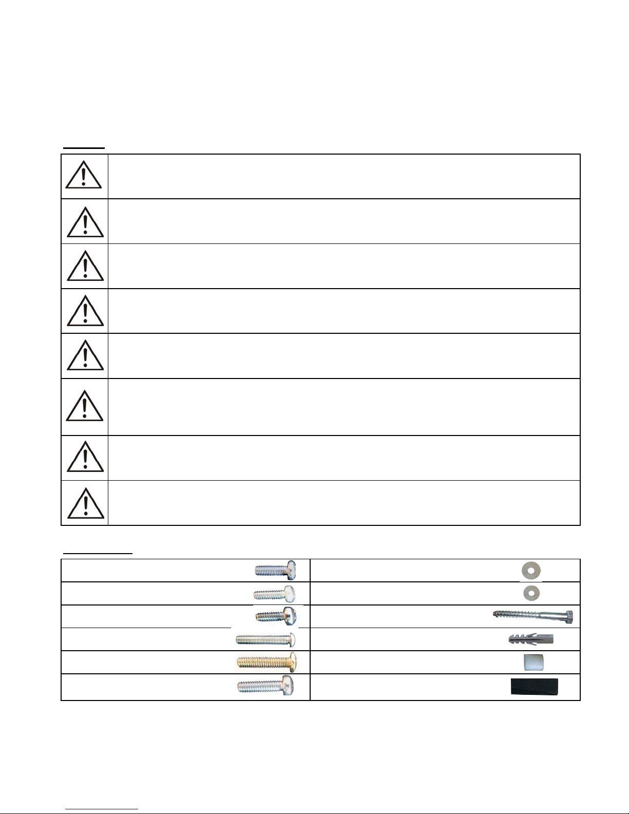
Hardware Kit
(×4) M5×16 screw (×4) M6 washer
AG
(×4) M6×16 screw
BH
(×4) M8×16 screw
CI
(×4) M5×35 screw (×4) Concrete anchor
DJ
(×4) M6×35 screw (×4) M8 spacer
EK
(×4) M8×35 screw (x2) Sponge sticker
FL
(x4) M5 washer
(×4) M8×80 bolt
2
Page 3
Tools Required
Phillips head screw driver
1
Stud finder for drywall installation
2
Level
3
1/2" socket & socket wrench and/or 1/2" open-end wrench
4
Drill, 3/16" (5mm) drill bit for wood stud installation and 3/8" (10mm) masonry drill bit for concrete/brick installation
5
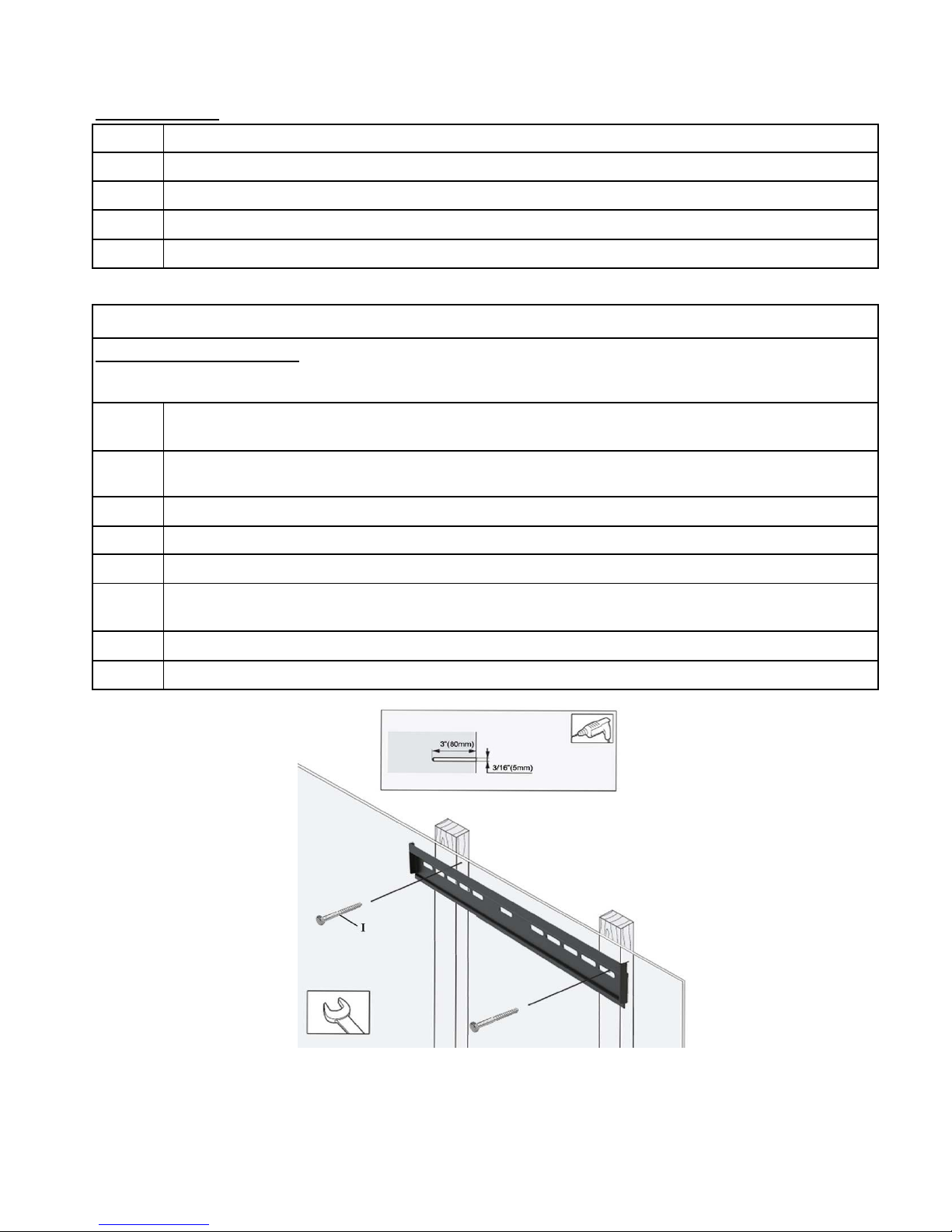
Step 1: Wall Plate Installation
a) Wood Stud Installation
NOTE: When mounting to wood studs, the two wood studs must be a minimum of 16" apart.
Use a high-quality electronic stud finder (commercially available) to locate dead center of two studs and mark
1
their locations with a pencil.
With the help of an assistant, and using a bubble level to ensure the wall plate is level, position the wall plate
2
against the wall in the desired mounting location.
Mark the right and the left positions of the small horizontal slots that are in alignment with the studs.
3
You should mark two positions total.
4
Pre-drill a 3/16" hole to a depth of approximately 3" in the wall stud at each marked location.
5
Place the wall plate against the wall and line up the mounting slots with the drilled holes. Check the bubble level
6
to verify that the wall plate is level.
For each location, insert bolt (I) into the wall.
7
Tighten the bolt with the 1/2" socket or 1/2" open-end wrench by turning clockwise until tight.
8
CAUTION: Do not over-tighten bolts - doing so may cause unnecessary damage to the wall.
CAUTION: Do not release the wall plate until it is properly mounted and secured to the wall.
3
Page 4

b) Concrete/Brick Installation
NOTE: The concrete anchors must be used for concrete installation.
With the help of an assistant, and using a bubble level to ensure the wall plate is level, position the wall plate
1
against the wall in the desired mounting location.
Mark four holes to be used for securing the mount and place the wall plate aside.
2
Next, drill holes using a 3/8" masonry drill bit to a depth of approximately 3".
3
Insert a concrete anchor into to each hole.
4
If necessary, a hammer can be used to lightly tap each anchor into place so that they are flush with the wall.
5
Once all of the anchors are in place, move the wall plate back into position.
6
Insert bolt (I) into each concrete anchor in the wall.
7
Do not tighten until all bolts are in place.
8
Tighten the bolt with the 1/2" socket or 1/2" open-end wrench by turning clockwise until tight.
9
CAUTION: Do not over-tighten bolts - doing so may cause unnecessary damage to the wall.
CAUTION: Do not release the wall plate until it is properly mounted and secured to the wall.
4
Page 5

Step 2: Display Bracket Installation
1
To ensure optimal installation, this kit includes various screws of different diameters and lengths.
Place your TV screen down on a soft, flat surface, and locate the threaded mounting points that are located on
2
the back of the display.
Determine which screw (A/B/C/D/E/F) is of the correct length by carefully inserting a straw, or toothpick, and
3
mark how deep the mounting point is.
According to the size of display's hole, choose the corresponding screw (A/B/C/D/E/F) and washer (G/H), then
4
thread them in line. Note: when using screw (C/F), no washer is needed. (figures a1, a2, a3)
If your display has a curved back or a recessed thread mounting point, a spacer (K) must be used. Then choose
5
screw (D/E/F) to match and place the spacer between the mounting bracket and display. (figure a5)
Cut strings to desired length (ensure enough string remains for easy access and use for installation & removal).
6
(figure a4)
Attach Sponge sticker (L) to the bottom inside of each TV rail. These will help to protect the wall surface. (figure
7
a6)
5
Page 6

Step 3: Final Installation & Adjustment
Hook the TV rails over the top of the wall plate and lower on to wall plate.
1
Pull TV forward from the bottom and connect all TV cables & wires.
2
To secure TV rails, pull strings down to retract locking mechanism & lower bottom of TV to the wall. Let go of
3
strings to engage the locking mechanism.
connect TV wires
Maintenance
Check the mounting screws every two months for tightness.
lock hook
Lift up TV ,
then pull down the belt
6
Page 7

Technical Support and Warranty
f
p
QUESTIONS? SIIG’s Online Support has answers! Simply visit our web site at www.siig.com and click Support. Our online
support database is updated daily with new drivers and solutions. Answers to your questions could be just a few clicks away.
You can also submit questions online and a technical support analysts will promptly respond.
SIIG offers a 5-year manufacturer warranty with this product. Please see our web site for more warranty details. If you
encounter any problems with this product, please follow the procedures below.
A) If it is within the store's return policy period, please return the product to the store where you purchased from.
B) I
your purchase has passed the store's return policy period, please follow these steps to have the product repaired or
re
laced.
Step 1: Submit your RMA request.
Go to www.siig.com, click Support, then click RMA to submit an request to SIIG RMA. If the product is determined to be
defective, an RMA number will be issued.
Step 2: After obtaining an RMA number, ship the product.
• Properly pack the product for shipping. All software, cable(s) and any other accessories that came with the original package
must be included.
• Clearly write your RMA number on the top of the returned package. SIIG will refuse to accept any shipping package, and will
not be responsible for a product returned without an RMA number posted on the outside of the shipping carton.
• You are responsible for the cost of shipping. Ship the product to the following address:
SIIG, Inc.
6078 Stewart Avenue
Fremont, CA 94538-3152, USA
RMA #: ________________
• SIIG will ship the repaired or replaced product via Ground in the U.S. and International Economy outside of the U.S. at no cost
to the customer.
7
Page 8

About SIIG, Inc.
Founded in 1985, SIIG, Inc. is a leading computer upgrade manufacturer of I/O connectivity products, including PCI
& ISA serial and parallel ports, USB, Serial ATA & UltraATA controllers, FireWire (1394a/b), networking, sound
cards, and other accessories. SIIG is the premier one-stop source of upgrades.
SIIG products offer comprehensive user manuals, many user-friendly features, and are backed by an extensive
manufacturer warranty. High-quality control standards are evident by the overall ease of installation and
compatibility of our products, as well as one of the lowest defective return rates in the industry. SIIG products can
be found in computer retail stores, mail order catalogs, through major distributors, system integrators, and VARs in
the Americas and the UK, and through e-commerce sites.
PRODUCT NAME
Ultra-Thin LED/LCD TV Mount - 32" to 55"
Ultra-Thin LED/LCD TV Mount - 32" to 55" is a trademark of SIIG, Inc. SIIG and the SIIG logo are registered trademarks of SIIG, Inc. Other
names used in this publication are for identification only and may be trademarks of their respective companies.
July, 2009 Copyright © 2009 by SIIG, Inc. All rights reserved.
8
 Loading...