

Page 1

SATA II-150 PCI
Quick Installation Guide
Introducing the SATA II-150 PCI
The SATA II-150 PCI is an ultra high-speed dual channel
Serial ATA Generation 2 controller for use in PCI enabled
systems.
Features and Benefits
• Add up to two high-speed SATA hard drives
• New Serial ATA cable – easier to install & provides
better air circulation
• Supports two SATA channels and data transfer rate
up to 1.5Gb/s (150MB/s)
• Supports Native Command Queuing (NCQ) and
SATA TCQ commands
• Onboard bus master engine relieves the system
processor from book keeping and enhances
performance
• Features independent 256-byte FIFOs per channel
for host reads and writes
• Breaks the 137GB barrier! Works with various
brands of large capacity Serial ATA hard disks
• Supports SATA hard disk hot-plugging
• Compliant with PCI 2.3
• Compliant with Serial ATA 1.0 specifications and
complement of SATA II optional features
04-0409A
1
Page 2
System Requirements
• Pentium or equivalent PC with an available PCI slot
• Windows 2000/XP/Server 2003
Package Contents
• SATA II-150 PCI and spare low profile bracket
• SATA data cable and power cable
• Driver CD and this quick installation guide
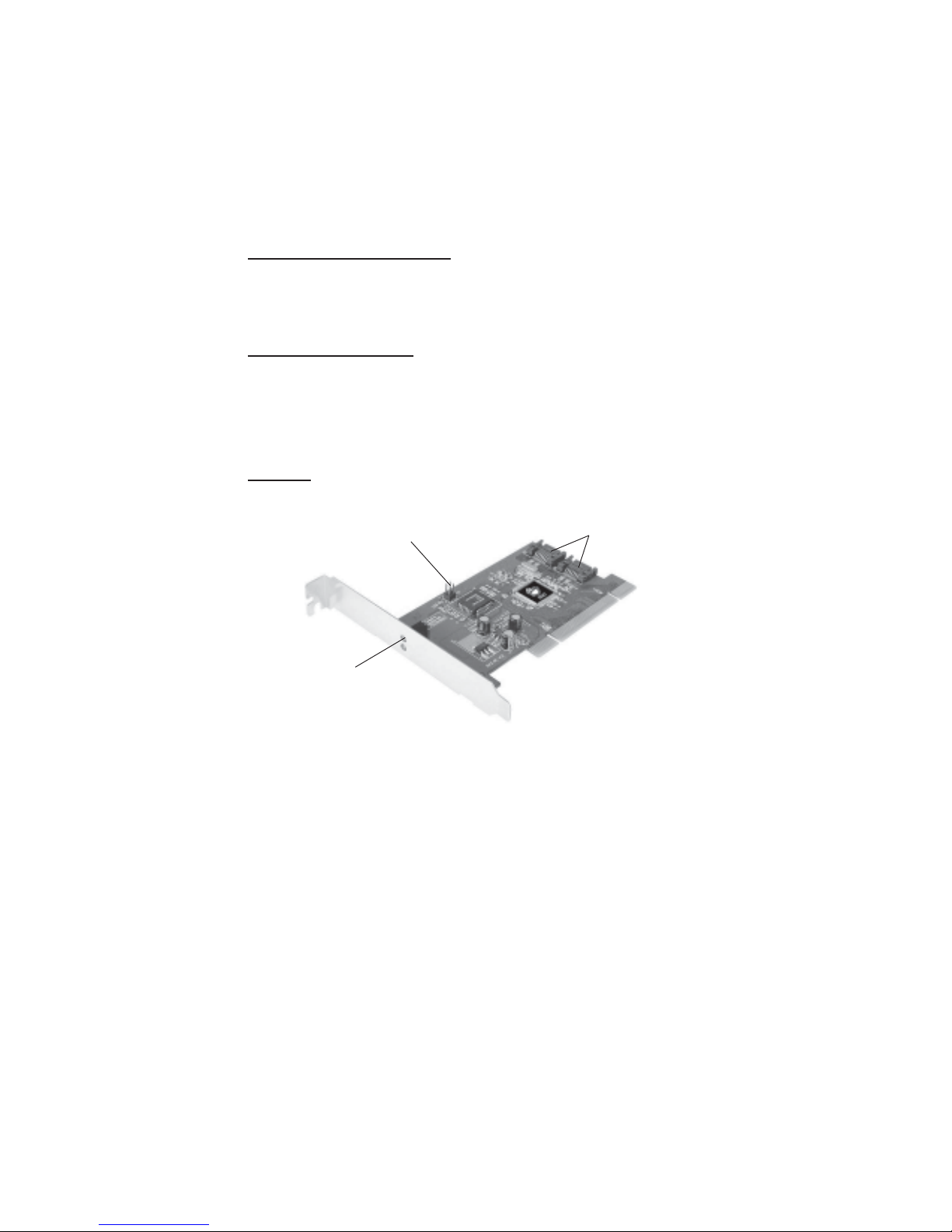
Layout
HDD LED pins (Front chassis LED;
connects horizontally)
HDD
Activity LED
Internal
connectors
Figure 1. SATA II-150 PCI Board Layout
2
Page 3

Hardware Installation
General instructions for installing the card are provided
below. Since the design of computer cases and
motherboards vary, refer to your computer’s reference
manual for further information, if needed.
Static Electricity Discharge may permanently damage
your system. Discharge any static electricity build up in
your body by touching your computer’s case for a few
seconds. Avoid any contact with internal parts and
handle cards only by their external edges.
1. Turn OFF the power to your computer and any
other connected peripheral devices.
2. Unplug the power cord from the back of the
computer.
3. Remove your computer’s cover.
4. Remove the slot bracket from an available PCI slot.
5. To install the card, carefully align the card's bus
connector with the selected PCI slot on the
motherboard. Push the board down firmly, but
gently, until it is well seated.
6. Replace the slot bracket's holding screw to secure
the card.
7. If needed, connect the HDD LED pins to monitor
HDD activity from the front panel of your chassis.
8. Replace the computer cover and reconnect the power
cord.
3
Page 4

Driver Installation
This section provides information on how to install the
SATA II-150 PCI drivers for the following operating
systems.
Windows 2000
New Windows 2000 Installation
A new installation of Windows 2000 requires a floppy
disk for the driver installation. To make this floppy disk,
copy the contents of the Floppy folder, found on the
driver CD, onto a blank floppy disk then follow the
directions below.
1. Install the board and follow the Microsoft
procedures to install Windows 2000 accordingly.
2. Restart your system when prompted during
Windows' installation.
3. At the Windows 2000 Setup screen, press F6 to
install the driver.
4. Insert the driver diskette. Press S, then press Enter.
5. Select INITIO INIC1620 S-ATA Adapter For
Windows 2000 and press Enter.
6. Press Enter to continue and follow on-screen
instructions to complete the installation.
Existing Windows 2000 Installation
1. Install the board and boot up Windows 2000.
2. At the Found New Hardware Wizard, click Next.
3. Select Search for a suitable driver for my device
(recommended) and click Next.
4. Insert the driver CD, check CD-ROM drives, uncheck
the other boxes, and click Next. Click Next again to
continue.
4
Page 5

5. Click Yes, then click Finish.
Note: Our driver has been thoroughly tested in
Windows for stability.
6. Restart Windows to complete the driver installation.
Windows XP/Server 2003
New Windows XP/Server 2003 Installation
A new installation of Windows XP/Server 2003 requires
a floppy disk for the driver installation. To make this
floppy disk, copy the contents of the Floppy folder,
found on the driver CD, onto a blank floppy disk then
follow the directions below.
1. Install the board and follow the Microsoft
procedures to install Windows accordingly.
2. Restart your system when prompted by Windows'
installation.
3. At the Windows Setup screen, press F6 to install the
driver.
4. Insert the driver diskette. Press S then press Enter.
5. Select INITIO INIC1620 S-ATA Adapter For
Windows XP/2003 and press Enter.
6. Press Enter to continue and follow on-screen
instructions to complete the installation.
Existing Windows XP/Server 2003 Installation
1. Install the board and boot up Windows
2. At the Found New Hardware Wizard:
XP (w/SP1 or earlier)/Server 2003: continue to step #3.
XP (w/SP2 or later)/Server 2003 (w/ SP1 or later): select
No, not at this time, then click Next.
5
Page 6

3. Insert the driver CD, select Install the software
automatically (Recommended), then click Next.
4. Click Continue Anyway, then click Finish. Click
Next again to continue.
Note: Our driver has been thoroughly tested in
Windows for stability.
5. Restart Windows to complete the driver installation.
To Verify Windows 2000/XP/2003 Installation
1. Right click My Computer and click Manage.
2. Select Device Manager.
3. Double click SCSI and RAID Controllers, then
double click Initio inic1620 S-ATA Adapter.
4. A message This device is working properly is displayed,
the driver has been correctly installed.
Hot-Plugging Hard Disk Drives
To remove a drive from a powered up system, do the
following:
1. Right click My Computer and click Manage.
2. Select Device Manager.
3. Click Disk Drives, right click the target disk and
select Disable/Enable.
4. You can now remove the target disk.
BIOS Configuration
The SATA II-150 PCI BIOS will appear everytime your
system starts up. If the BIOS doesn't show, please try
your controller in another PCI slot. During this (Post)
process, the BIOS will show up and indicate the devices
attached to it.
6
Page 7

Technical Support and Warranty
QUESTIONS? SIIG’s Online Support has answers!
Simply visit our website at www.siig.com and click on Support.
Our online support database is updated daily with new drivers
and solutions. Answers to your questions could be just a few clicks
away. You can also submit questions online and one of our technical
support analysts will promptly respond.
A lifetime manufacturer warranty supplied with this product is
offered by SIIG, Inc. Please see SIIG website for more warranty
details. If you should happen to encounter any problems with this
product, please follow the procedures below.
If it is within the store's return policy period, please return the
product to the store where you purchased from.
If your purchase has passed the store's return policy period, please
follow these steps to have the product repaired or replaced.
Step 1: Submit your RMA request.
Go to www.siig.com, click Support, then RMA to submit a
request to SIIG RMA. If the product is determined to be
defective, an RMA number will be issued. SIIG RMA department
can also be reached at (510)413-5333.
Step 2: After obtaining an RMA number, ship the product.
• Properly pack the product for shipping. All software, cable(s)
and any other accessories that came with the original package
must be included.
• Clearly write your RMA number on the top of the returned
package. SIIG will refuse to accept any shipping package, and
will not be responsible for a product returned without an
RMA number posted on the outside of the shipping carton.
• You are responsible for the cost of shipping the product to
SIIG at the following address:
SIIG, Inc.
6078 Stewart Avenue
Fremont, CA 94538
RMA #: _________________
• SIIG will ship the repaired or replaced product via Ground
in the U.S and International Economy outside of the U.S at
no cost to the customer.
7
Page 8

About SIIG, Inc.
Founded in 1985, SIIG, Inc. is a leading computer upgrade manufacturer
of I/O connectivity products, including PCI & ISA serial and parallel
ports, USB, Serial ATA & UltraATA controllers, FireWire (1394a/b),
Networking, Sound Cards, and other accessories. SIIG is the premier
one-stop source of upgrades.
SIIG products offer comprehensive user manuals, many user-friendly
features, and are backed by an extensive manufacturer warranty.
High-quality control standards are evident by the overall ease of
installation and compatibility of our products, as well as one of the
lowest defective return rates in the industry. SIIG products can be
found in computer retail stores, mail order catalogs, and e-commerce
sites in the Americas and the UK, as well as through major
distributors, system integrators, and VARs.
PRODUCT NAME
SATA II-150 PCI
FCC RULES: TESTED TO COMPLY WITH FCC PART 15, CLASS
B OPERATING ENVIRONMENT: FOR HOME OR OFFICE USE
FCC COMPLIANCE STATEMENT:
This device complies with part 15 of the FCC Rules. Operation is
subject to the following two conditions: (1) This device may not cause
harmful interference, and (2) this device must accept any interference
received, including interference that may cause undesired operation.
THE PARTY RESPONSIBLE FOR PRODUCT COMPLIANCE
SIIG, Inc.
6078 Stewart Ave.
Fremont, CA 94538-3152
SATA II-150 PCI is a trademark of SIIG, Inc.
SIIG and SIIG logo are registered trademarks of SIIG, Inc. Microsoft and Windows are
registered trademarks of Microsoft Corporation. Other names used in publication are for identification
only and may be trademarks of their respective companies.
January, 2006 Copyright © 2005 by SIIG, Inc. All rights reserved.
 Loading...