

Page 1
1
SATA RAID 1+Backup
Bay Enclosure
Quick Installation Guide
04-0432A
Introducing the SATA RAID 1+Backup
The SATA RAID 1+Backup Bay Enclosure is a Serial ATA
RAID enclosure for use in Serial ATA enabled systems.
Features and Benefits
• Hardware-based RAID 1+Backup bay solution
• Driverless: needs no driver on the host side
• Hot swappable hard disks
• Automatic on-line data rebuilding and bad sector
recovery
• Key lock security against unauthorized access
• LED indicators for disk status disply and event
notification through audible alarm
• Java-based GUI for system status monitoring
System Requirements
• Serial ATA-enabled system with an available
Serial ATA port/channel
• Windows 2000/XP/Server 2003
Page 2
2
Package Contents
• SATA RAID 1+Backup Bay Enclosure
• Disk drives mounting screws
• Two keys for drive carriers (identical)
• Null modem (9-/9-pin) and (3-/9-pin) serial cables
• "Y" split power & SATA data cables
• Quick Installation Guide and RAID GUI software
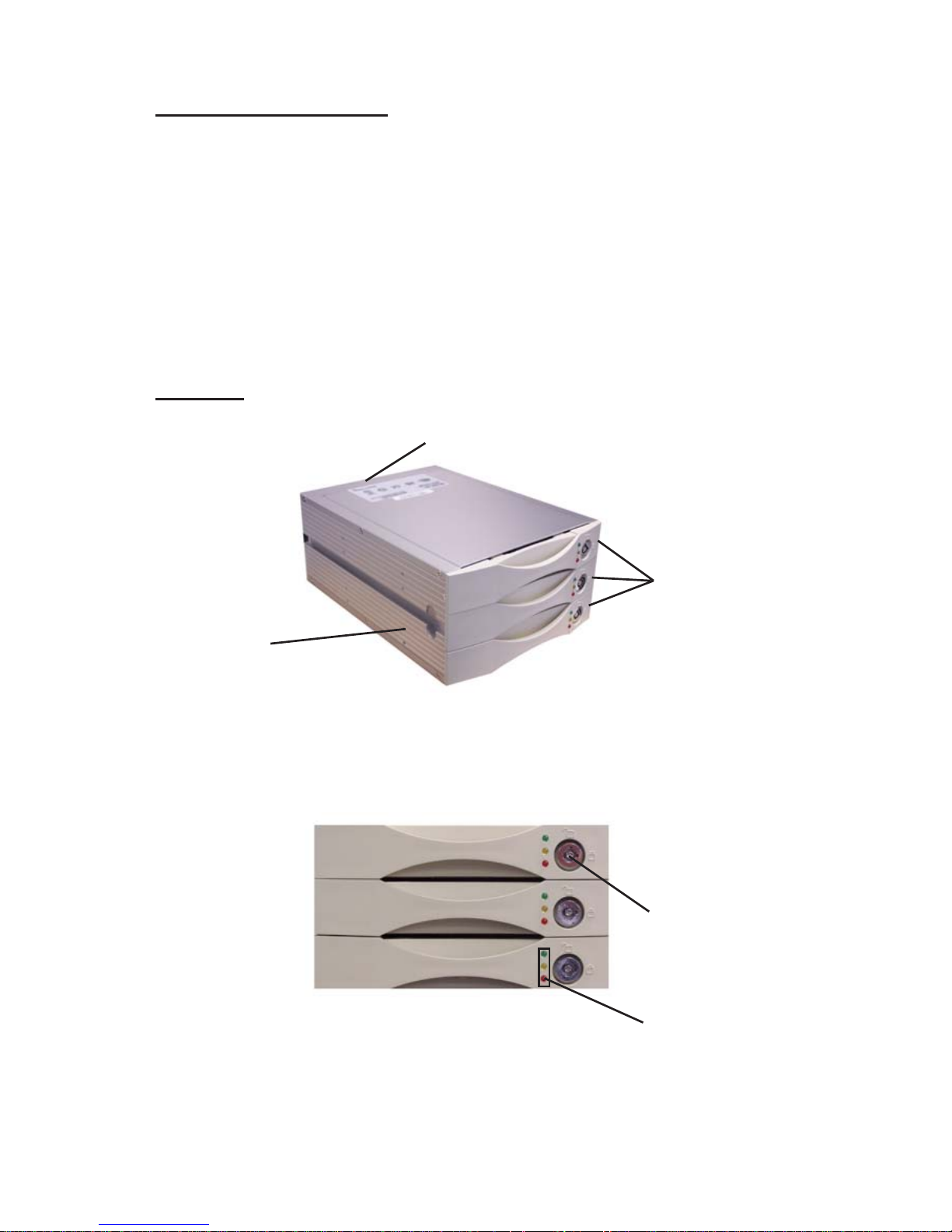
Layout
Holes for mounting
screws
Figure 1: Layout
Drive carrier
lock
Disk activity
indicators
Figure 2: Front view
Three drive
carriers
Rear connectors and jumpers
Page 3

3
Figure 3: 3-/9-pin serial cable
9-pin RS232 female connector
Figure 4: Null Modem cable
3-pin RS232
connector
9-pin RS232
male connector
Page 4

4
Unlocked orientation
Locked
orientation
Green disk activity indicator
Amber disk
activity indicator
Figure 5: Disk activity indicators
Red disk activity indicator
Disk Activity Indicators
These indicators show the status of each individual disk
drive.
Green = Disk drive is properly installed and locked
Amber = Disk drive is being accessed
Red = Disk drive is not present, not properly installed,
unlocked, or disk has failed
Red Flashing = Disk drive is rebuilding data
Red slow Flashing = The backup disk marking at the rate
of 0.5sec/on-2sec./off (move in circle)
In the event that a drive fails, the Red indicator turns on
and an alarm will sound (beeping). You can turn off the
alarm by unlocking the drive carrier.
The drive carrier lock acts as an On/Off switch for the
drives and provide security by preventing no-key holders
from accessing the drives.
To lock each carrier, insert the key, shown on Figure 6.
Turn it in a clockwise direction. To unlock a carrier, turn
the key in a counterclockwise direction.
Page 5

5
Figure 6: Inserting key
Power
connectors
SATA interface connector
3-pin RS232 connector
(Terminal Port)
RAID level
configuration
jumper pins
Cooling fan vent
Figure 7: Rear view
The power connector supplies power to the RAID box.
Connect both power connectors on the RAID box using
the provided "Y" split power cable.
The 3-pin RS232 serial cable is used for remote monitoring
of SIIG RAID box. The RS232 port is configured with DTE
and PC compatible pin assignments.
Page 6
6
There is a triangular symbol on both 3-/9-pin serial cable
connector and 3-pin RS232 connector on the RAID box,
please make sure you connect in the right direction (both
triangle symbols match each other). Connecting in wrong
direction will not damage RAID controller, however the
terminal or GUI will not work.
The cooling fan inside the RAID box provides air
circulation for the disk drives.
Note: Do not change the RAID level configuration
jumpers. They have been set and ready for use
when the RAID box is delivered.
Hardware Installation
The SATA RAID 1+Backup Bay Enclosure fits into two half
height 5 1/4" drive bays. General instructions for installing
the box are provided below. Since the design of computer
cases and motherboards vary, refer to your computer’s
reference manual for further information, if needed.
Static Electricity Discharge may permanently damage
your system. Discharge any static electricity build up in
your body by touching your computer’s case for a few
seconds.
1. Turn OFF the power to your computer and any
other connected peripheral devices.
2. Unplug the power cord from the back of the
computer.
3. Open your computer case.
4. Remove the front cover from your system case.
5. Feed two power cables, the SATA data cable and the
RS232 cable through the opening.
Page 7

7
6. Connect a power cable to both power connectors.
Use the "Y" split power cable to provide an extra
power connector, if needed.
7. Connect the serial cable to the 3-pin RS232 connector.
Make sure the triangle on the connector is pointing
to Pin 1 of the connector, see Figure 8.
Figure 8: Connecting 3-pin RS232 cable
8. Connect the SATA data cable to the SATA connector
on the RAID box.
Figure 9. Cable Connections
Page 8

8
9. Slide the RAID box into the drive bay and secure it
on each side using the mounting screws.
10. Remove the bracket from the back of the chassis
from an available expansion slot. Install the
connector bracket with 9-pin serial port and secure
it with a mounting screw. Connect one end of the
null modem cable to the 9-pin serial port and the
other end to an available serial port of the system.
11. Do not connect the SATA data cable to the SATA
controller until after the RAID array has finished
initializing. See Initializing RAID Array on page 11
for more information.
Figure 10: Inserting SATA RAID 1+Backup Bay Enclosure
Page 9

9
Source
Target
Spare for backup
RAID 1
Spare drive
Figure 11: RAID box
Backup function
When executing the backup feature, the controller turns
the target HDD to be backup and the backup HDD to be
target. The controller continues to mirror data from the
source HDD to the target HDD.
The backup function is available only when the RAID is
safe. If the RAID health is in good state, you may execute
the backup function. The RAID health refers to the state
of both the source and target HDD. Failure of either of the
HDDs causes unsafe RAID.
The source disk has to be the first HDD, shown on
Figure 11.
Note: Installing the backup drive is optional and
can be added at a later time. If there's no disk drive
installed in the bottom drive carrier, the RAID box
is operating in RAID 1 mode with no backup
functionality. When this happens, the green and
red LED's will light up.
Page 10

10
Loading the Drive into the Carrier
The SATA RAID 1+Backup Bay Enclosure should be fitted
with three hard disk drives. Load each drive into a drive
carrier as follows:
1. Unlock the drive carrier and slide out of the RAID
box.
2. Place the disk drive in the drive carrier, so that the
SATA connector is lined up with the connector
inside the carrier.
3. Carefully push the disk drive so that the drive's
SATA connector is seated securely into the SATA
connectore in the disk carrier, shown in Figure 12.
4. Secure the disk drive by screwing it to the drive
carrier case.
5. Slide the loaded disk drive carrier into the SATA
RAID 1+Backup Bay Enclosure but do not lock it. See
Initializing RAID Array on page 11 for more
information.
Figure 12: Inserting hard disk drive
Note: The disk carrier connector at the back of each
SATA RAID 1+Backup Bay Enclosure disk carrier slot
can be damaged if the disk carrier is not properly
aligned when inserted. Insert the disk carrier gently
to avoid damage.
Page 11

11
Removing/Replacing a Drive
Swapping drives:
The hot swap function is available on the RAID 1 array
and can be operated during run time. RAID rebuilding
will be processed automatically in the background and
the RAID box will record its progress. If the host system
is shut down or powered off abnormally, the RAID box
will continue the disk rebuilding process after power is
turned on again.
What if a disk fails?
If a disk drive fails, or a key switch is turned off, the red
disk activity indicator of its disk carrier will light and the
alarm will sound (sound when only disk fails). When this
happens, you can replace the failed disk with a new one,
and then turn the key switch on.
Removing a drive from a fixed connector drive carrier:
1. Unlock the appropriate drive carrier. The red disk
activity indicator will light.
2. Slide the drive carrier out of its slot.
3. Slide the disk drive to the front of the carrier so that
the SATA connector is freed from the drive carrier.
4. Lift out the disk drive.
Hard Disk Initialization
This section explains how to start using the
SATA RAID 1+Backup Bay Enclosure.
If you have installed three new disk drives, go to
Initialization 1.
If you have installed one hard disk with data and two
blank/new disk drives, go to Initialization 2.
Page 12

12
Initialization 1: Three new disk drives
1. Turn your computer off.
2. Lock all drive carriers and they are ready for use.
3. If you have installed non-identical hard disk drives,
your computer will recognize the SATA
RAID 1+Backup Bay Enclosure as a single hard disk
with a capacity equal to the smaller hard disk drive
installed in the RAID box.
4. Turn your computer on.
The status of all indicators during boot-up:
Be sure to put three hard disks into the three drive
carriers while the system is booting.
Disk Activity Indicator During Array Initialization
During array initialization, the following will be
observed:
• Green: solid
• Yellow: solid
• Red: flashing
Initialization 2: One hard disk with data and two
blank/new disk drives
1. Turn your computer on.
2. Install the hard disk with data into the top drive
carrier and locked it. This will serve as a source
drive.
3. Install your blank/new disk drive into second drive
carrier and locked it. This will serve as a target
drive.
4. Install the second blank/new disk drive into the
third drive carrier and locked it. This will serve as
a backup drive.
Page 13

13
Note: If the disk drives in steps 3 & 4 contain any
data, it will be erased once the RAID box is setup
and initialized.
5. If you have installed non-identical hard disk drives,
your computer will recognize SATA RAID 1+Backup
Bay Enclosure as a single hard disk with a capacity
equal to the smaller hard disk drive installed in the
RAID box.
The status of all indicators during boot-up:
Be sure to put the disk drive with data in the first drive
carrier and the new two hard drives into the last two drive
carriers respectively while the system is booting.
Disk Activity Indicator During Array Initialization
During array initialization, the following will be
observed:
• Green: solid
• Yellow: solid
• Red: flashing
Note: Installing the backup drive is optional and
can be added at a later time. If there's no disk drive
installed in the bottom drive carrier, the RAID box
is operating in RAID 1 mode with no backup
functionality. When this happens, the green and
red LED's will light up.
Software Installation
Connect the SATA RAID 1+Backup Bay Enclosure to a
Serial ATA port/channel. Windows 2000/XP/Server
2003 will automatically detect the RAID box.
Page 14

14
To Verify Windows 2000/XP/2003 Installation
1. Right click My Computer, then click Manage. Click
Device Manager.
2. Double click Disk drives, SIIG RAID 1+Backup...
should be displayed.
SIIGView GUI Installation
The SIIGView Graphical User Interface (GUI) provides a
web-based, real time, local monitoring of your SATA
RAID 1+Backup Bay Enclosure.
1. Place the driver installation CD into the CD-ROM
drive. Auto-run should start the installation. If not,
click Start, then Run. Type D:\autorun, then click
OK. (Change D: to match your CD-ROM drive
letter).
2. At the SIIGView window, click the SIIGView button.
3. At the SIIGView 1.0 Setup window, click Next.
4. Check I Agree to the terms ...., click Next.
5. Type a Name and Company (if desired), click Next.
6. Accept the default folder, click Next.
7. At the Shortcut folder, select the option that best fits
your needs, then click Next.
8. Click Next to proceed with the install.
9. When prompted, click Finish. Close the SIIGView
install window.
10. Two shortcut icons will appear on the desktop after
software installation:
SIIGView Server: to launch SIIGView software
program.
SIIGView Monitor: to open the SIIGView
monitoring window.
Page 15

15
SIIGView GUI
In order for SIIGView GUI to operate, the RAID box must
be connected to a serial port on your system. Please refer
to step #10 on page 8 for more information.
SIIGView Server
The first time SIIGView Server is run, it will detect the
COM port it is installed onto. Please follow the directions
below to complete the installation.
1. To start SIIGView Server, click Start, Programs,
RAID Utility, SIIGView then SIIGView Server or
double click the SIIGView Server icon on the
desktop.
2. At the Detect Option box, select Yes, then click OK.
3. The SIIGView Server icon will appear on the taskbar
by the system clock.
SIIGView Server Menu Options
Run at Windows Startup
Allows SIIGView Server to startup automatically at
Windows startup.
1. Right click the SIIGView Server icon that appears
on the taskbar by the system clock.
2. Left click Run at Windows Startup.
Enable/Disable Warning Message
Allows SIIGView Server to pop up warning message
window when an event occurs. (Default is disable)
1. Right click the SIIGView Server icon that appears
on the taskbar by the system clock.
2. Click Enable Warning Message or Disable Warning
Message.
Page 16

16
Config Setup
Configures email alert so that in the event of a RAID
failure, the RAID administrator will be notified
immediately.
1. Right click the SIIGView Server icon that appears
on the taskbar by the system clock.
2. Click Config Setup.
3. Enter the following information:
Mail Server: Enter the IP address of the mail server
on your network. If no mail server information is
added, the mail alert function will be disabled.
IP Address: Enter the IP address of the mail server
on your network. The entries in the top two boxes
should be identical.
Administrator's Email: Enter the email address for
one or two administrators.
Delay Time (Minute): Alert emails will continue to
be sent until the problem is resolved. The email
events are fan fail, disk status (off line, fails,
rebuilding) and RAID fails. Enter the desired time
lapse between successive emails (Default = 1 minute)
4. Click Save to save your changes.
SIIGView Monitor
The very first time running SIIGView Monitor, Java
Runtime will install. Follow the directions to install the
software.
1. Select I accept the terms ..., click Next.
2. Select Typical, click Next.
3. Click Finish to complete the installation. The
SIIGView browser window will automatically open.
Page 17

17
Introducing the SIIGView Browser
Inside the SIIGView browser window, the following
information is displayed:
• Fan status: Provides alert in case of fan malfunction
• Controller tabs: Allow you to select which controller
to monitor.
• Battery status: Provides alert in case of battery
malfunction.
• Warning message option: Enable / Disable
pop-up message. SIIGView browser will pop-up
message window when event occur, if this option is
enable. (Default is enabling)
• Controller information: Lists model name, serial
number and RAID level of the RAID kit.
• Disk status: Allows you to monitor the status of
each of the disk drives.
• Hard drive information: Lists model name and
capacity of each of the disk drives.
• Re-build / initialize progress: Tracks the re-building
or initialization process.
• Message window: Provides controller number,
date, time, error message when event occur.
Page 18

18
FAQ
If you encounter a problem while using the
SATA RAID 1+Backup Bay Enclosure, check this section
for help.
1. When I lock a drive carrier with a disk drive in
place, the red disk activity indicator turns on and
an alarm beep sounds. Why?
• Make sure you firmly connect the SATA connector
of the HDD to their counterparts inside the drive
carrier and try again. If this does not solve the
situation, go to next suggestion below.
• Change the disk drive with a new one and try
again.
• Exchange the top and bottom drive carriers and try
again to determine if the carrier itself is faulty.
• If all of the above steps fail, contact SIIG Technical
Support.
2. How can I turn off the alarm beep sound when
there is a hard disk failure?
• Unlock the drive carrier of the failed disk. This will
turn off the alarm beep sound.
Page 19

19
Technical Support and Warranty
QUESTIONS? SIIG’s Online Support has answers!
Simply visit our website at www.siig.com and click on Support.
Our online support database is updated daily with new drivers
and solutions. Answers to your questions could be just a few clicks
away. You can also submit questions online and one of our technical
support analysts will promptly respond.
This product comes with a 5-year manufacturer warranty. Please see
SIIG website for more warranty details. If you should happen to have
any problems with this product, follow the procedures below.
A) If it is within the store's return policy period, please return the
product to the store where you purchased from.
B) If your purchase has passed the store's return policy period, please
follow these steps to have the product repaired or replaced.
Step 1: Submit your RMA request.
Go to www.siig.com, click Support, then RMA to submit a
request to SIIG RMA. If the product is determined to be
defective, an RMA number will be issued. SIIG RMA department
can also be reached at (510)413-5333.
Step 2: After obtaining an RMA number, ship the product.
• Properly pack the product for shipping. All software, cable(s)
and any other accessories that came with the original package
must be included.
• Clearly write your RMA number on the top of the returned
package. SIIG will refuse to accept any shipping package, and
will not be responsible for a product returned without an
RMA number posted on the outside of the shipping carton.
• You are responsible for the cost of shipping. Ship the product
to the following address:
SIIG, Inc.
6078 Stewart Avenue
Fremont, CA 94538
RMA #:
• SIIG will ship the repaired or replaced product via Ground
in the U.S. and International Economy outside of the U.S. at
no cost to the customer.
Page 20

SATA RAID 1+Backup Bay Enclosure is a trademark of SIIG, Inc. SIIG and SIIG logo are registered
trademarks of SIIG, Inc. Microsoft and Windows are registered trademarks of Microsoft Corporation.
Other names used in this publication are for identification only and may be trademarks of their
respective companies.
August, 2006 Copyright ©2006 by SIIG, Inc. All rights reserved.
PRODUCT NAME
SATA RAID 1+Backup Bay Enclosure
FCC RULES: TESTED TO COMPLY WITH FCC PART 15, CLASS
B OPERATING ENVIRONMENT: FOR HOME OR OFFICE USE
FCC COMPLIANCE STATEMENT:
This device complies with part 15 of the FCC Rules. Operation is
subject to the following two conditions: (1) This device may not cause
harmful interference, and (2) this device must accept any interference
received, including interference that may cause undesired operation.
THE PARTY RESPONSIBLE FOR PRODUCT COMPLIANCE
SIIG, Inc.
6078 Stewart Ave.
Fremont, CA 94538-3152
About SIIG, Inc.
Founded in 1985, SIIG, Inc. is a leading computer upgrade manufacturer
of I/O connectivity products, including PCI & ISA serial and parallel
ports, USB, Serial ATA & UltraATA controllers, FireWire (1394a/b),
Networking, Sound Cards, and other accessories. SIIG is the premier
one-stop source of upgrades.
SIIG products offer comprehensive user manuals, many user-friendly
features, and are backed by an extensive manufacturer warranty.
High-quality control standards are evident by the overall ease of
installation and compatibility of our products, as well as one of the
lowest defective return rates in the industry. SIIG products can be
found in computer retail stores, mail order catalogs, and e-commerce
sites in the Americas and the UK, as well as through major distributors,
system integrators, and VARs.
 Loading...