

Page 1
PRODUCT NAME MODEL NUMBER
PC Switch 2000 DC0201
FCC RULES: TESTED TO COMPL Y WITH FCC PART 15, CLASS B
OPERA TING ENVIRONMENT : FOR HOME OR OFFICE USE
FCC COMPLIANCE STATEMENT:
This device complies with part 15 of the FCC Rules. Operation is subject to
the following two conditions: (1) This device may not cause harmful
interference, and (2) this device must accept any interference received,
including interference that may cause undesired operation.
FCC NOTICE:
This equipment has been tested and found to comply with the limits for a
Class B digital device, pursuant to part 15 of the FCC Rules. These limits are
designed to provide reasonable protection against harmful interference in a
residential installation. This equipment generates, uses, and can radiate radio
frequency energy and if not installed and used in accordance with the
instructions, may cause harmful interference to radio communications.
However, there is no guarantee that interference will not occur in a particular
installation. If this equipment does cause harmful interference to radio and
television reception, which can be determined by turning the equipment off
and on, the user is encouraged to try to correct the interference by one or more
of the following measures:
• Reorient or relocate the receiving antenna
• Increase the separation between the equipment and the receiver
• Connect the equipment into an outlet on a circuit different from that to
which the receiver is connected
• Consult the dealer or an experienced radio or TV technician for help
Any changes or modifications not expressly approved by the party
responsible for compliance could void the user's authority to operate
this equipment
THE PARTY RESPONSIBLE FOR
PRODUCT COMPLIANCE
Fremont, CA 94538-3152
PC Switch 2000 is a trademark of SIIG, Inc.
SIIG and SIIG logo are registered trademarks of SIIG, Inc. Microsoft, Windows, and
Windows NT are registered trademarks of Microsoft Corporation. Pentium is a registered
trademark of Intel Corporation. Other names used in this publication are for identification
purposes only and may be trademarks of their respective companies.
Caution:
SIIG, Inc.
6078 Stewart Ave.
(510) 657-8688
PC Switch 2000
Installation Guide
This installation guide provides instructions for installing your
PC Switch 2000.
Introducing the
The PC Switch 2000 is designed for user to access multiple
computers using only one console. By pressing HOT keys from
the keyboard directly or the SELECT button on the switch, you
can easily switch from one computer to another.
Key Features
• CPU switch to control 2 servers or workstations
• Switches between PCs using hot-keys or push-button
• Auto-scan for periodic monitoring of PCs
• Built-in buzzer for switching confirmation
• Mouse and keyboard emulation for inactive PCs
• Active LEDs for status monitoring
• Keyboard status (Caps Lock, Num Lock and Scroll Lock)
restored while switching between PCs
• Scan mode automatically switches through power-on
computers, scan rate is DIP switch selectable
• Supports VGA, SVGA and Multisync monitors
• Supports VGA resolutions up to 1280 x 1024 pixels
System Requirements
Console
• PS/2 or serial mouse
• VGA, SVGA or Multisync monitor with cable
• AT or PS/2 keyboard with the included PS/2-to-AT adapter
PC Switch 2000
July, 1999 Copyright ©1999 by SIIG, Inc. All rights reserved.
04-0160A
1
Page 2
System Requirements (continue)
Technical Support
PC
• VGA, SVGA or Multisync video port
• PS/2 or serial mouse port
• AT or PS/2 keyboard port with the included PS/2-to-AT
adapter
• Cable kit—Each PC requires an individual cable kit to connect
to the PC Switch 2000. Cable kit is sold separately. Refer to
the Accessory Table for cable type to work with your PCs.
Package Contents
• One PC Switch 2000
• One linear power adapter
• One 1-year warranty card
• Three PS/2(F)-to-AT(M) keyboard adapter
• This quick installation guide
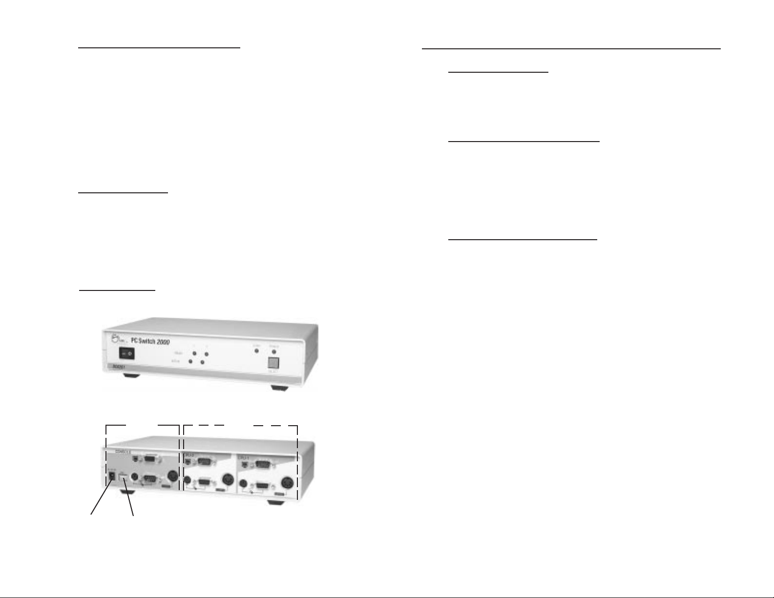
Product Layout
Front View
Web Online Support
Question? SIIG’s Online Support has answers! Simply go to
SIIG’s web site at
www.siig.com
and click on the ONLINE
SUPPORT icon for instant technical support service.
Technical Support Department
For additional support, SIIG's Technical Support Specialists are
available from 8:00 a.m. to 5:00 p.m. Monday through Friday,
Pacific Standard Time. To reach a Technical Support Specialist:
e-mail: support@siig.com
Telephone: (510) 353-7542
Customer Service Department
If the Technical Support Specialist determines that the product
may be defective, you can return it for repair or replacement.
Step 1: Call SIIG's Customer Service Department
Call the Customer Service Department at (510) 657-8688 ext.
5333 for a Return Merchandise Authorization (RMA) number.
Please have the product serial number available. It is located on
the side of the box and on the back of the product.
2
Back View
Power
Jack
Console
Section
Dip
Switch
CPU
Section
Figure 1: PC Switch 2000 Layout
Step 2: Complete the RMA form
• Fill out your Return Merchandise Authorization (RMA) form,
and include it in the package along with the original materials.
• Clearly write your RMA number on the outside of the returned
shipping package and on the accompanying RMA form.
SIIG will refuse to accept any shipping package, and not
be responsible for a product returned without a RMA
number posted on the outside of the shipping carton.
Step 3: Ship the PC Switch 2000
You are responsible for the cost of shipping the product back to
SIIG at the following address:
SIIG, Inc. RMA#_______________
6078 Stewart Ave.
Fremont, CA 94538
SIIG will ship the repaired or replaced product via UPS Ground
or US Mail at no cost to you.
Page 3

DIP Switch Settings
Connector Types
The default DIP Switch setting is configured for 5 seconds scan
interval. If you like to reconfigure the scan interval, refer to the
table below:
DIP DIP Scan DIP Switch
Switch 1 Switch 2 Interval Setting
On On 5 seconds
(Default setting)
O
123
N
4
Off On 10 seconds
O
123
N
4
On Off 20 seconds
O
123
N
4
Off Off 40 seconds
O
123
N
4
Note Make sure to turn the PC Switch 2000 off to reconfigure the
setting. DIP Switches 3 and 4 should always be set ON.
Accessory Table
The following connector types are illustrated for your reference
when making device connection:
Keyboard Mouse Video
AT (5-Pin DIN) Serial (DB9) HDDB15 (Male)
PS/2 (6-Pin DIN) PS/2 (6-Pin DIN) HDDB15 (Female)
Installation
The PC Switch 2000 can control up to 2 PCs. Proceed with the
following steps to setup the PC Switch 2000:
!!! CAUTION !!!
Make sure all devices are powered off
when making connections.
The following high quality cable kits are designed to work with
the PC Switch 2000. You may purchase them through your
distributor.
SIIG
Part No.
Length
(ft.)
DC-CBK612 6 AT Serial HDDB15
DC-CBKA12 10 AT Serial HDDB15
DC-CBK622 6 PS/2 HDDB15
DC-CBKA22 10 PS/2 HDDB15
6
Device Connector Types
Keyboard Mouse Video
To Setup the Console
1. Connect the keyboard, mouse and monitor to the Console
section on the PC Switch 2000. And plug the power adapter
into the power jack.
2. If you have a 9-pin serial mouse port on one PC and a PS/2
port on the other, you need to connect both types of mouse
to the Console for controlling both PCs correspondingly.
3. For your convenience, the PS/2 to AT keyboard adapter is
provided for connecting a keyboard with PS/2 connector to
the Console.
3
Page 4

To Setup the PC
To Activate the SCAN Mode
1. Connect the mouse, keyboard, and video (DB15/Female)
connector of the cable kit to the CPU-1 on the PC Switch 2000.
Then connect all the connectors on the other end of the cable
kit to the first PC. (Use the PS/2-to-AT keyboard adapter if
needed).
2. Repeat step 1 to setup the second PC.
3. Turn on the PC Switch 2000 first, then the PCs.
Operations
The PC Switch 2000 comes with the following LEDs for user’s
friendly operation:
POWER LED: To indicate the PC Switch 2000 is powered on
and ready.
SCAN LED: To indicate the PC Switch 2000 is under the
SCAN mode.
READY LED: To indicate the corresponding PC is powered
on.
ACTIVE LED: To indicate the current selected operating PC.
You can monitor the PCs by pressing the SELECT button, or the
HOT keys on the console keyboard. Also, you can configure the
DIP Switch on the back panel of the PC Switch 2000 to set the
scanning interval (see next section for DIP Switch Settings).
Press the SELECT button:
Press the SELECT button and hold it over one second.
The SCAN LED will light on with two beeps.
To stop the SCAN mode and return to Normal operation,
press the SELECT button and release it within one second.
The SCAN LED will be off.
Press the HOT keys:
Press and release the HOT keys (Ctrl, Alt and Shift) on the
console keyboard simultaneously. Followed by entering
the number 0 and press Enter.
For example: Ctrl + Alt + Shift è 0 è Enter
To stop the SCAN mode and return to Normal operation,
press the Space bar of the keyboard.
To Access the PC
You can access to the connected PCs by pressing the SELECT
button on the front panel of the PC Switch 2000, or the HOT keys
on the console keyboard.
Press the SELECT button:
Press the SELECT button and release it within one second.
The ACTIVE LED will advance to the next corresponding
PC’s LED with a beep sound.
Press the HOT keys:
Press and release the HOT keys (Ctrl, Alt and Shift) on the
console keyboard simultaneously. Followed by entering a
corresponding PC’s number (#) and press Enter.
For example: Ctrl + Alt + Shift è a number è Enter
4
5
 Loading...