

SIIG PCI Express Serial Quick Installation Manual

DP Industrial PCI Express
Serial Adapter Card
Quick Installation Guide
Introduction
The DP Industrial PCI Express Serial Adapter Card
is a high-speed serial card that provides
additional serial ports to your system.
Key Features and Benefits
• Provides serial ports to PCI Express enabled
system.
• Supports serial port data transfer rate up to
921.6Kb/s
• Built-in 15KVDC ESD serial interface
protection
• Built in 128-byte FIFO buffer for ID-E80011S1 & ID-E80111-S1; built-in 256-byte FIFO
buffer for ID-E20211-S1
• Built in H/W, S/W data direction flow
control
04-0821B
1

System Requirements
• Desktop PC with an available PCIe slot
• Windows® 8 (32-/64-bit) / 7 (32-/64-bit) /
Vista (32-/64-bit) / XP (32-/64-bit) / Server
2003 & 2008 (32-/64-bit) / Server 2008 R2
/ 2000
Package Contents
• DP Industrial PCI Express Serial Adapter
Card
• Connector adapter cable:
For ID-E20211-S1: 2x RJ-45 to DB9 (male)
cable
For ID-E80011-S1 & ID-E80111-S1:
1x VHDI68 to 8-port DB9 (male) cable
• Spare low profile bracket
• Driver CD
• Quick installation guide
2
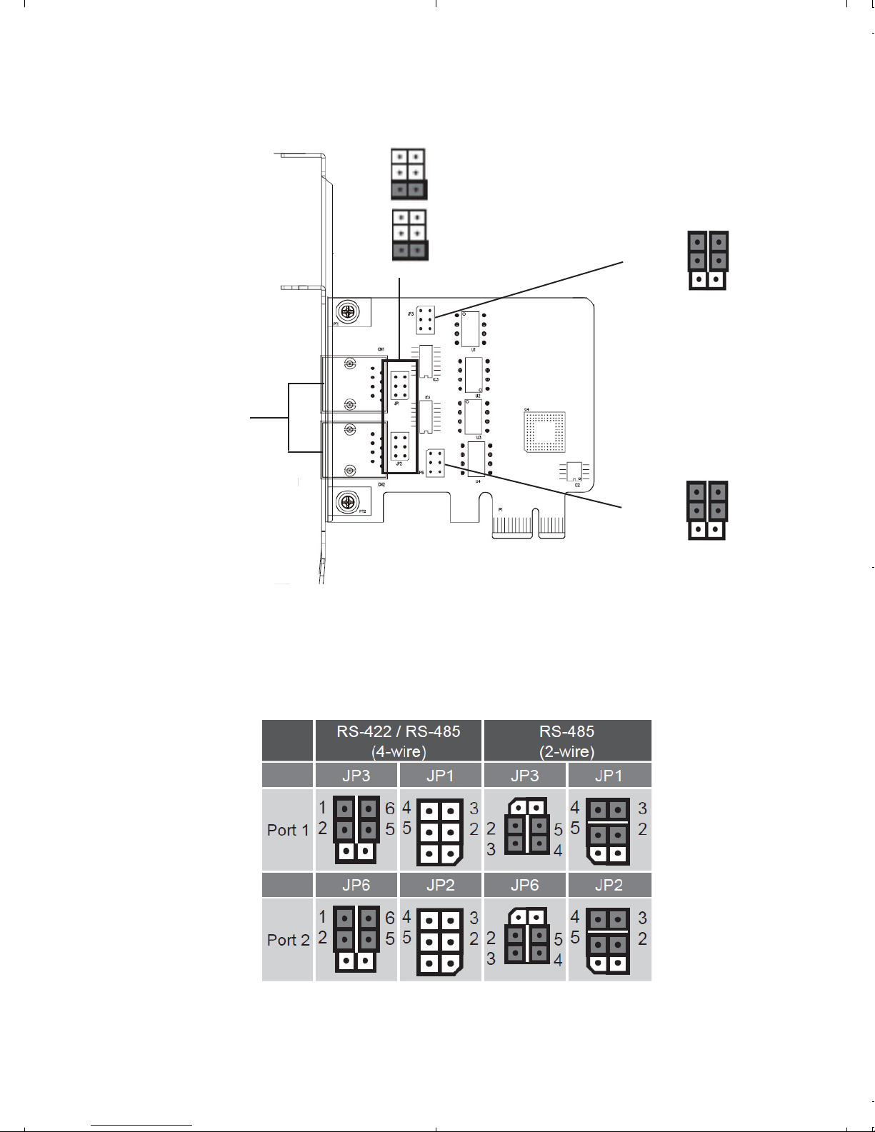
Layout
RJ 45 port
JP1*
JP2*
1
6
5
1
JP3
1
2
1
JP6
2
* NOTE: Short JP1 and JP2 for 120 ohm terminal resistance to get signal reflection
elimination.
Figure 1: ID-E20211-S1 Layout
6
5
Figure 2: ID-E20211-S1 Jumper Setting
3
4
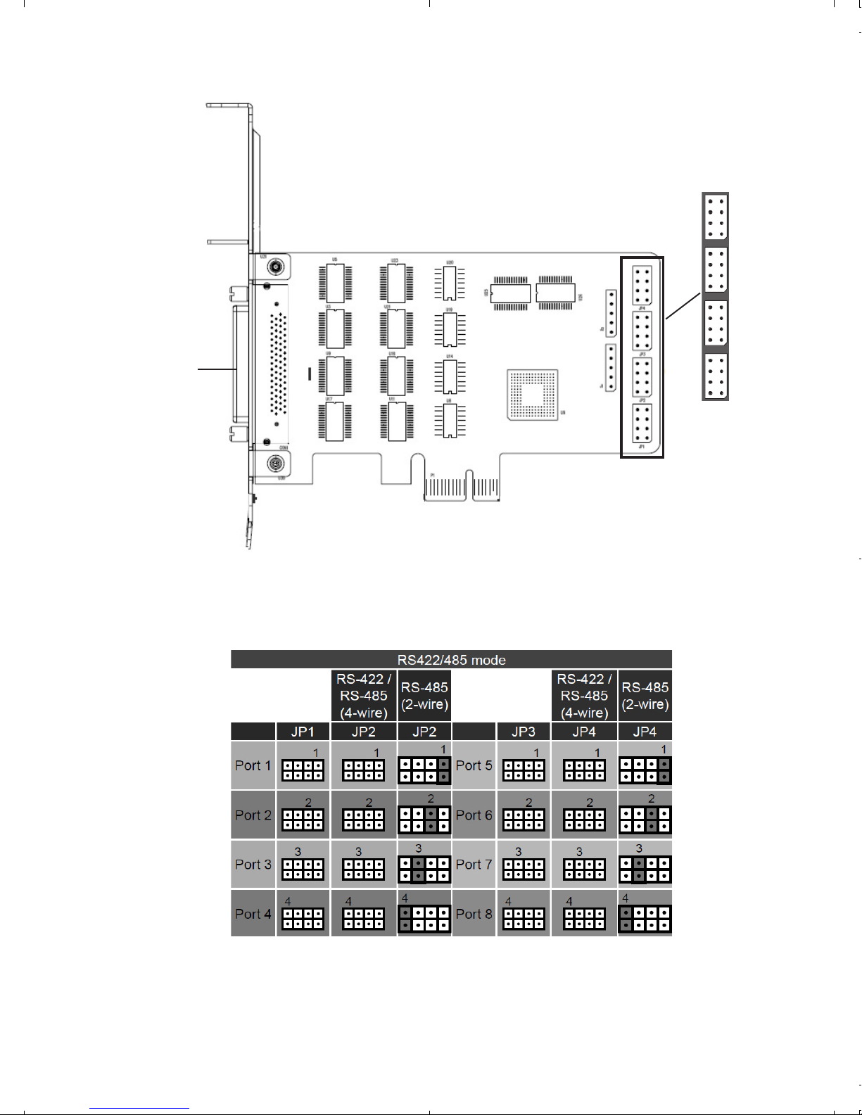
1
JP1
JP2
JP3
VHDI68 port
JP4
Figure 3: ID-E80111-S1 Layout
Figure 4: ID-E80111-S1 Jumper Setting - RS-422/485
4
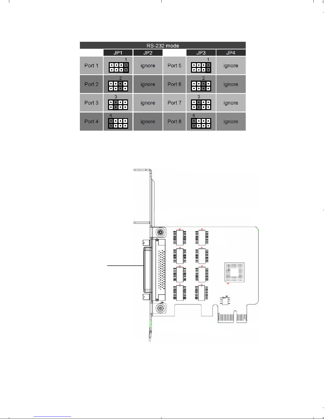
Figure 5: ID-E80111-S1 Jumper Setting - RS-232
VHDI68 port
Figure 6: ID-E80011-S1 Layout
5
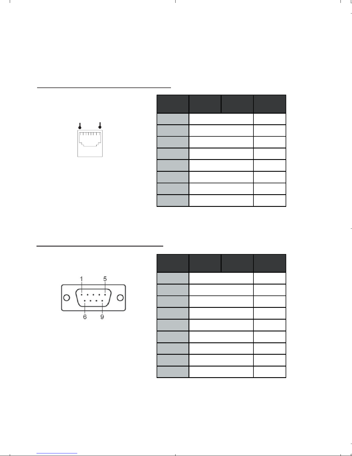
Pin Assignment
ID-E20211-S1 Pin Assignment
RJ-45 Pin Assignment
18
Figure 7: ID-E20211-S1 RJ-45 pin assignment
DB9 Pin Assignment
RJ45 Pin# RS-422
1 RxD-(A )
2RxD+(B)
3GND
4NCNC
5NCNC
6 TxD-(A) Da ta-(A)
7NC
8 TxD+(B) Data+(B)
DB9 Pin# RS-422
RS-485
(4-wire)
RS-485
(4-wire)
RS-48 5
(2-wire)
RS-48 5
(2-wire)
1 TxD-(A) Data-(A)
2NCNC
3NCNC
4 TxD+(B) Data+(B)
5GND
6 RxD-(A)
7RxD+(B)
8NC
9NC
Note: For RS-485 (2-wire), need to control input (RTS) and output (DTR).
Figure 8: ID-E20211-S1 DB9 pin assignment
6
 Loading...