

SIIG JU-91RW12-S4 Quick Installation Manual
1
Introducing the Reader/Writer+Floppy
The Reader/Writer+Floppy is the perfect choice for
computer users who need a flash memory card
reader/writer that supports multiple card formats as
well as reads Floppy disks.
Features and Benefits
• Fits into either 3.5" or 5.25" (with included mounting
rack) drive bay
• Dual color Activity/Access LED:
- Red: Flash memory card interface
- Green: Floppy drive interface
Flash memory card interface:
• Compliant with USB specification rev. 2.0
• Works with CompactFlash (CF) Type I & Type II,
Microdrive, SmartMedia (SM), SecureDigital (SD),
MultimediaCard (MMC) and Memory Stick
(incl. MagicGate & Pro) memory cards
Note: USB 2.0 devices are limited to USB 1.1
speeds when they are connected to a USB 1.1 host
adapter.
Floppy drive interface:
• Supports 1.44MB and 2MB Floppy disks
04-0361A
USB 2.0 9-in-1 R/W+FDD
Quick Installation Guide
2
System Requirements
• PC computer with an internal USB port
(USB 2.0 recommended)
• One available 3.5" or 5.25" drive bay
• CD-ROM drive (for driver installation)
• Windows 98SE/ME/2000/XP/Server 2003
Package Contents
• USB 2.0 9-in-1 R/W+FDD
• (1) 5.25 inch mounting rack
• (1) 4-pin header-to-type A USB adapter
• (1) Driver installation CD
• (1) Bag assorted mounting screws
• Quick installation guide
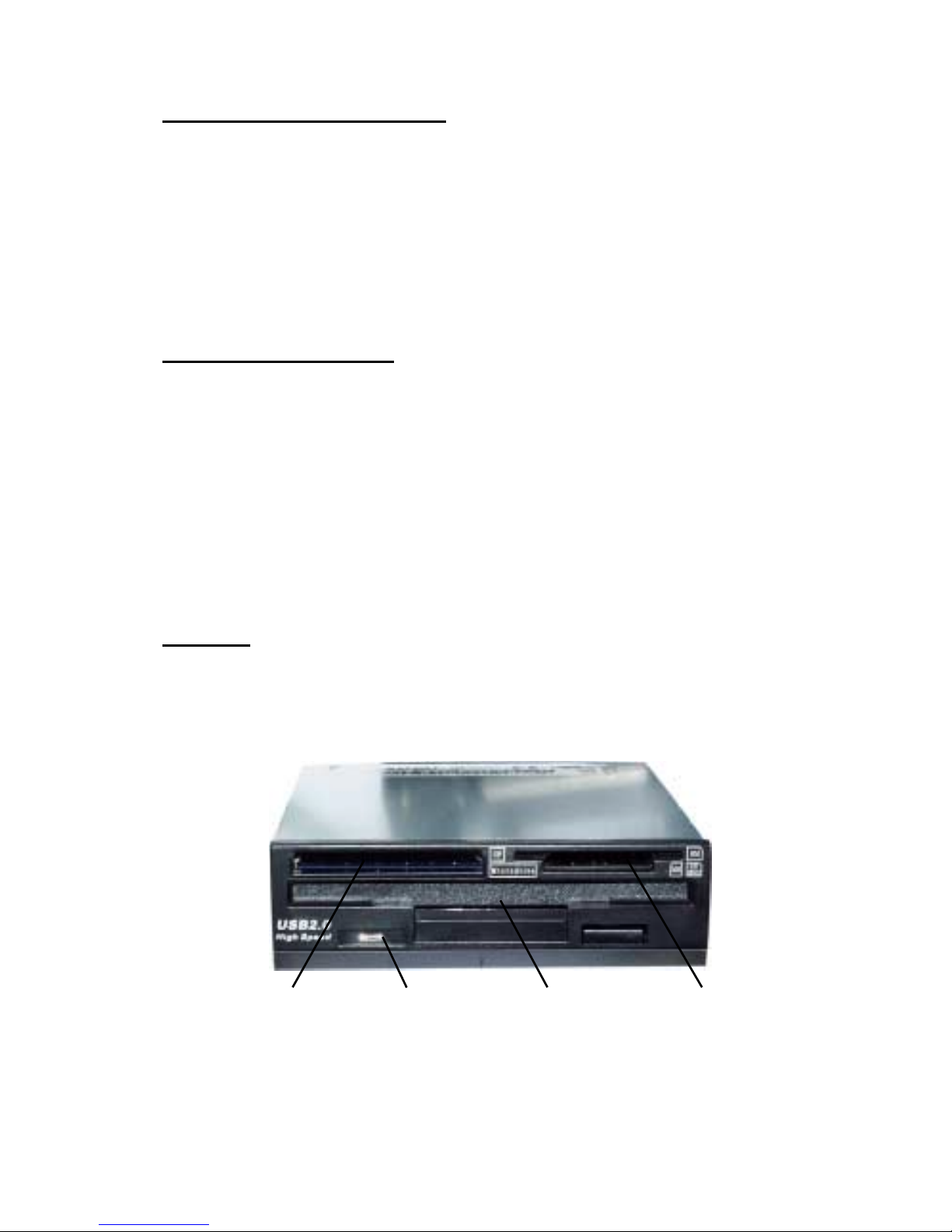
Layout
Depending on the model purchased, the color of your
product may vary from what is shown.
SM/SD/MMC/
Memory Stick
CF/Microdrive Floppy diskActivity/Access
LED
Figure 1. Front Panel Layout
3
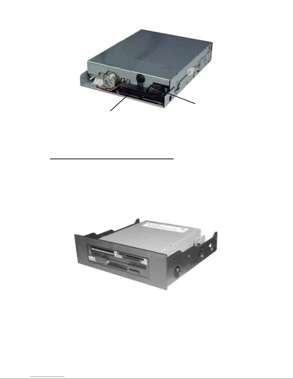
Figure 2. Rear Layout
5.25" Mounting Rack Assembly
Important: Use the Mounting Rack Assembly only
when installing the hub into a 5.25" drive bay. Depending
on the model purchased, the color of your product may
vary from what is shown.
Floppy drive
connector
Power
connector
Figure 3. 5.25" Mounting Rack Assembly

4
4-pin USB Connector
Figure 4. 4-pin USB Connector
USB Pin-out Header
On most motherboards, the USB header/pin-out consists
of 9 pins arranged in 2 rows; and each header allows for
2 USB connections (i.e. USB1 and USB2). Normally, the
pins for USB1 and USB2 are in seperate rows.
DATA -
DATA +
GND
GND
DATA -
DATA +
+ 5VDC
+5VDC
S-GND
Red
Black
Green
White
USB1
USB2
Pin Assignments
Figure 5. USB Pin-out Header
Note: See Figure 4, above, for proper orientation
of the 4-pin USB connector.
 Loading...