

Page 1

1
CyberPro PCI 4S
Quick Installation Guide
04-0346C
Introducing the CyberPro PCI 4S
The CyberPro PCI 4S high-speed serial I/O card provides
four additional 9-pin serial ports.
Features and Benefits
• Conforms to PCI v2.2 Plug and Play
• Full support for Windows-based software
• Reduces CPU load and improves system
performance dramatically
• IRQ sharing feature reduces IRQ conflicts
• High-speed serial port (9-pin) works with 56K V.90
external modems, ISDN terminal adapters, PDAs,
digital cameras, label printers and other serial port
devices
• Built-in FIFO buffers dramatically increase data
transmit/receive speed, especially under Windows'
multitasking environment
• Each serial port can be configured for either 5v or
12v output, for serial devices that require additional
power
System Requirements
• Pentium or equivalent computer with an available
PCI slot
• Windows® 95/98/98SE/ME/NT 4.0/2000/XP (32-
/64-bit)/Server 2003 (32-/64-bit)/Vista (32-/64-bit)
Page 2
2
Package Contents
• CyberPro PCI 4S board
• Slot bracket with 2 DB9 (9-pin) serial ports
• Driver CD
• Quick Installation Guide
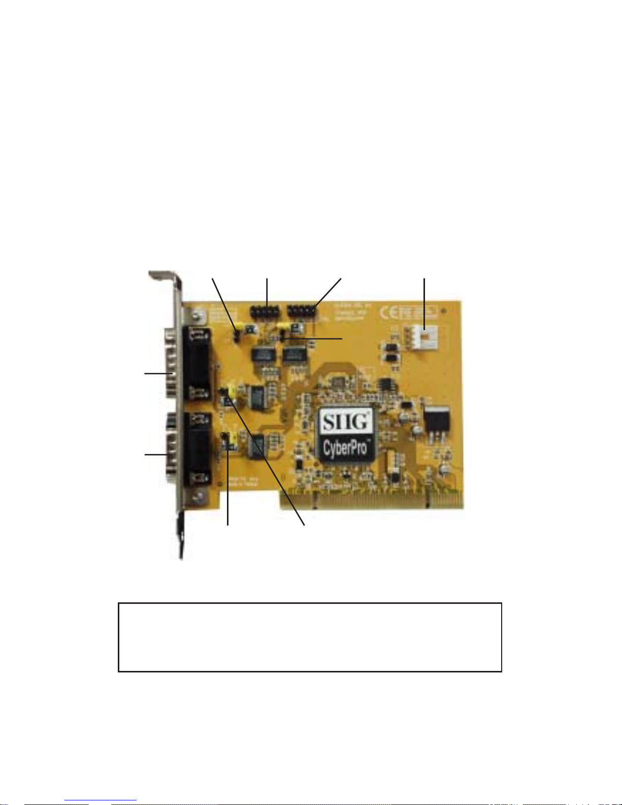
Layout
4-pin power
connector
(optional)*
JP1
(P1)
JP4
(P4)
JP2
(P2)
JP3
(P3)
Serial
port 3
(P3)
Serial
port 1
(P1)
Serial
port 4
(P4)
Serial
port 2
(P2)
Figure 1. Layout
* Note: Make this connection only when two or
more serial ports are configured for 5V/12V
output.
Page 3
3
Jumper Settings (JP1, JP2, JP3, JP4)
Open = 0 volts (default)
Short 1-2 = 5V
Short 2-3 = 12V
Note: Most serial devices do not require additional
power through the serial port. Refer to your serial
device's manual for more information. The jumpers
can be removed if the ports do not need power.
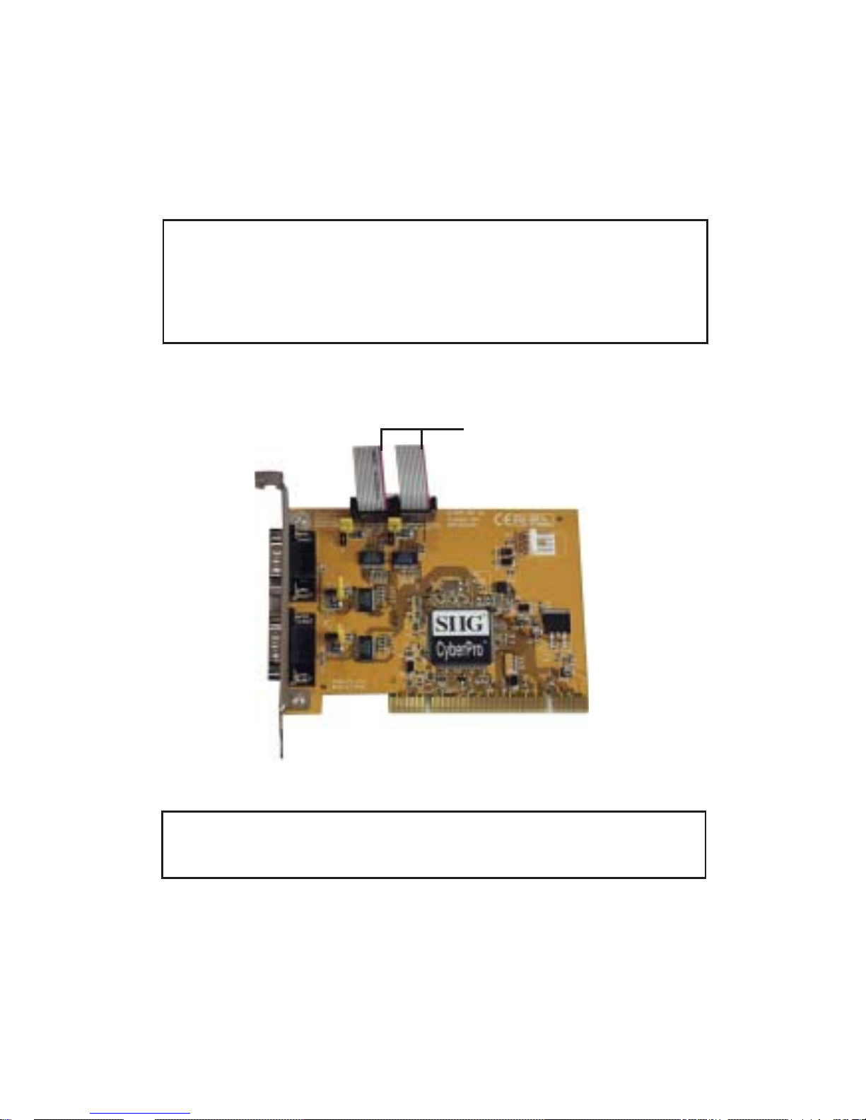
Serial Port 3 and 4 Connection
Figure 2. Connecting the ribbon cable
Note: This connection is needed only if port 3 and
4 are needed.
Stripe
Page 4

4
Hardware Installation
General instructions for installing the card are provided
below. Since the design of the computer cases and
motherboards vary, refer to your computer’s reference
manual for further information, if needed.
Static Electricity Discharge may permanently damage
your system. Discharge any static electricity build up in
your body by touching your computer’s case for a few
seconds. Avoid any contact with internal parts and
handle cards only by their external edges.
1. Turn OFF the power to your computer and any
other connected peripheral devices.
2. Unplug the power cord from the computer.
3. Remove your computer’s cover.
4. Remove the slot bracket from an available PCI slot.
5. Set JP1-JP4 jumper settings to the desired voltage
only if your serial device(s) needs additional power
from the serial port. However, most serial devices
do not require additional power. For more
information go to Figure 1 on page 2. Skip this step
if power is not required.
6. If you need four serial ports, connect the 2-port
ribbon cable connector now. See Figure 2 on page 3
for more details. Skip this step if you only need two
serial ports.
7. To install the card, carefully align the card's bus
connector with the selected PCI slot on the
motherboard. Push the board down firmly, but
gently, until it is well seated.
8. Replace the slot bracket holding screw to secure the
card.
9. Replace the computer cover and reconnect the power
cord.
Page 5

5
Driver Installation
This section provides information on how to install the
CyberPro PCI 4S drivers.
Windows 95
1. At the Update Device Driver Wizard, click Next.
2. Insert the driver CD, and click Other Locations.
Type in D:\9x, click OK, then Finish. (Change D: to
match your CD-ROM drive letter)
3. From the Insert Disk window, click OK. When the
Copying Files dialog box appears, type in
D:\9x, then click OK.
4. Restart Windows to complete the installation.
Windows 98/98SE
1. At the Add New Hardware Wizard, click Next.
2. Select Search for the best driver for your device
(Recommend), then click Next.
3. Select Specify a location, uncheck the other boxes,
insert the driver CD, type in D:\9x, then click Next.
(Change D: to match your CD-ROM drive letter)
4. Click Next, then Finish.
5. Repeat steps 1-4.
6. Restart Windows to complete the installation.
Windows ME
1. At the Add New Hardware Wizard, select Specify
the location of the driver (Advanced), then click
Next.
Page 6

6
2. Insert the driver CD, check Specify a location,
uncheck the other box, type in D:\Me, then click
Next. (Change D: to match your CD-ROM drive
letter)
3. Click Next, Next, and Finish.
4. Repeat steps 1 - 3.
5. Restart Windows to complete the installation.
To Verify Windows 95/98/98SE/ME Installation
1. From the main desktop, right click My Computer,
click Properties, then click Device Manager.
2. Double click Ports (COM & LPT), CyberSerial PCI
16Cxxx... should be displayed four times.
3. Double click Multi-function adapters, SIIG
CyberPro 4S PCI board and PCI Function should
be displayed.
Windows NT 4.0
1. From the desktop click Start, then Run.
2. Insert the driver CD, type in
D:\NT4\Install_Serial.exe, then click OK. (Change
D: to match your CD-ROM drive letter)
3. Click Next when the Welcome window appears.
4. Choose Install, then click Next.
5. Click Yes, then click Exit.
6. Restart Windows to complete the installation.
To Verify Windows NT 4.0 Installation
1. Click Start, Settings, Control Panel. Double click
Ports device icon.
2. Four new COM ports will be assigned when
successfully installed.
Page 7

7
Windows 2000
1. At the Found New Hardware Wizard, click Next.
2. Select Search for a suitable driver for my device
(recommended), and click Next.
3. Check Specify a location, uncheck the other boxes,
and click Next.
4. Insert the driver CD, type in D:\2000, then click OK.
(Change D: to match your CD-ROM drive letter)
5. Click Next and Finish.
6. Repeat steps 1-5 two more times.
7. Restart Windows to complete the installation.
32-bit Windows XP/Server 2003
1. At the Found New Hardware Wizard, insert the
driver CD.
For XP w/SP1 or earlier/ Server 2003: go to step #2.
For XP w/SP2 or later/Server 2003 wSP1 or later: select
No, not this time, click Next.
2. Select Install the software automatically
(Recommended, then click Next.
3. Click Finish.
4. Repeat steps 1-3 two more times.
5. Restart Windows to complete the installation.
64-bit Windows XP/Server 2003
1. At the Found New Hardware Wizard, insert the
driver CD.
For XP w/SP1 or earlier/ Server 2003: go to step #2.
For XP w/SP2 or later/Server 2003 wSP1 or later: select
No, not this time, click Next.
2. Select Install the software automatically
(Recommended, then click Next.
Page 8

8
3. Click Continue Anyway, then click Finish.
4. Repeat steps 1-3 several more times.
5. Restart Windows to complete the installation.
To Verify Windows 2000/XP/Server 2003
Installation
1. Right click My Computer, click Manage, then select
Device Manager.
2. Click on the + (plus sign) in front of Ports (COM &
LPT), CyberSerial PCI 16Cxxx... should be
displayed four times.
3. Double click Multifunction adapters, SIIG
CyberPro 4S PCI board should be displayed.
Windows Vista
™
1. At the Found New Hardware window, insert the
driver CD, click Locate and install driver software
(recommended), then click Continue.
2. Click Next, then click Close.
3. Repeat step #2 to complete the driver installation.
Note: Windows Vista driver installation process
may take several minutes to complete.
To Verify Windows Vista Installation
1. Right click Computer, click Manage, click Continue,
then click Device Manager.
2. Click on the + (plus sign) in front of Ports (COM &
LPT), CyberSerial 16Cxxx... should be displayed
four times.
3. Double click Multifunction adapters, SIIG
CyberPro 4S PCI board should be displayed.
Page 9

9
Changing COM Port Address
Some serial devices need a specific COM port in order to
work. If your serial device works properly, do not
change this setting.
Windows 95/98/98SE/ME
1. From the Device Manager window double click
Ports (COM & LPT), then double click the
CyberSerial PCI serial port you want to change.
2. Click Settings tab, click the down arrow that is next
to the Port Name box and select a COM address that
is not currently in use.
3. Click OK, then close Device Manager to save the
changes. Follow steps 1-3 again to change the other serial
port(s) if needed.
Windows 2000/XP/Server 2003/Vista
1. From the Device Manager window double click
Ports (COM & LPT), then double click the
CyberSerial PCI serial port you want to change.
2. Click Settings tab and click Advanced.
3. Click the down arrow that is next to the COM Port
number box and select a COM port that is not in use.
Click OK.
4. Click OK, then close Device Manager to save the
changes. Follow steps 1-4 again to change the other serial
port(s) if needed.
Page 10

10
Blank Page
Page 11

11
Technical Support and Warranty
QUESTIONS? SIIG’s Online Support has answers! Simply visit our
web site at www.siig.com and click Support. Our online support
database is updated daily with new drivers and solutions. Answers
to your questions could be just a few clicks away. You can also submit
questions online and a technical support analysts will promptly
respond.
SIIG offers a lifetime manufacturer warranty with this product. Please
see our web site for more warranty details. If you encounter any
problems with this product, please follow the procedures below.
A) If it is within the store's return policy period, please return the
product to the store where you purchased from.
B) If your purchase has passed the store's return policy period, please
follow these steps to have the product repaired or replaced.
Step 1: Submit your RMA request.
Go to www.siig.com, click Support, then RMA to submit a
request to SIIG RMA. If the product is determined to be
defective, an RMA number will be issued. SIIG RMA department
can also be reached at (510) 413-5333.
Step 2: After obtaining an RMA number, ship the product.
• Properly pack the product for shipping. All software, cable(s)
and any other accessories that came with the original package
must be included.
• Clearly write your RMA number on the top of the returned
package. SIIG will refuse to accept any shipping package, and
will not be responsible for a product returned without an
RMA number posted on the outside of the shipping carton.
• You are responsible for the cost of shipping. Ship the product
to the following address:
SIIG, Inc.
6078 Stewart Avenue
Fremont, CA 94538-3152, USA
RMA #:
• SIIG will ship the repaired or replaced product via Ground
in the U.S. and International Economy outside of the U.S. at
no cost to the customer.
Page 12

CyberPro PCI 4S is a trademark of SIIG, Inc. SIIG and the SIIG logo are registered trademarks of SIIG,
Inc. Microsoft, Windows and Windows Vista are registered trademarks of Microsoft Corporation.
Pentium is a registered trademark of Intel Corporation. Other names used in this publication are for
identification only and may be trademarks of their respective companies.
October, 2007 Copyright © 2007 by SIIG, Inc. All rights reserved.
About SIIG, Inc.
Founded in 1985, SIIG, Inc. is a leading computer upgrade manufacturer
of I/O connectivity products, including PCI & ISA serial and parallel
ports, USB, Serial ATA & UltraATA controllers, FireWire (1394a/b),
networking, sound cards, and other accessories. SIIG is the premier
one-stop source of upgrades.
SIIG products offer comprehensive user manuals, many user-friendly
features, and are backed by an extensive manufacturer warranty.
High-quality control standards are evident by the overall ease of
installation and compatibility of our products, as well as one of the
lowest defective return rates in the industry. SIIG products can be
found in computer retail stores, mail order catalogs, through major
distributors, system integrators, and VARs in the Americas and the
UK, and through e-commerce sites.
PRODUCT NAME
CyberPro PCI 4S
FCC RULES: TESTED TO COMPLY WITH FCC PART 15, CLASS
B OPERATING ENVIRONMENT: FOR HOME OR OFFICE USE
FCC COMPLIANCE STATEMENT:
This device complies with part 15 of the FCC Rules. Operation is
subject to the following two conditions: (1) This device may not cause
harmful interference, and (2) this device must accept any interference
received, including interference that may cause undesired operation.
THE PARTY RESPONSIBLE FOR PRODUCT COMPLIANCE
SIIG, Inc.
6078 Stewart Avenue
Fremont, CA 94538-3152, USA
 Loading...