

SIIG ID-UC0011-S1, ID-US0011-S1 Quick Installation Manual
USB to RS-422/485
Converter
Quick Installation Guide
Introduction
The USB to RS-422/485 Converter is designed to convert
USB signals to RS-422/485 compatible signal.
Features and Benefits
• Auto detect between RS-422 or RS-485 signal
• Zero jumper configuration
• 15KV ESD immunity, surge protection and short
circuit protection
• USB port powered; no AC adapter required
System Requirements
• Pentium® II or equivalent PC with an available USB
port
• Windows® 8 (32-/64-bit) / 7 (32-/64-bit) / Vista
(32-/64-bit) / XP (32-/64-bit) / Server 2003 (32-/
64-bit) / Server 2008 (32-/64-bit) / Server 2008 R2 /
2000
• Linux 2.6 / 3.x
Serial Number Sticker
For future product return or exchange, this serial number
is required. Please keep it for your reference.
04-0484B
Serial Number Part Number
1
Package Contents
• USB to RS-422/485 Converter
• USB cable
• Quick installation guide
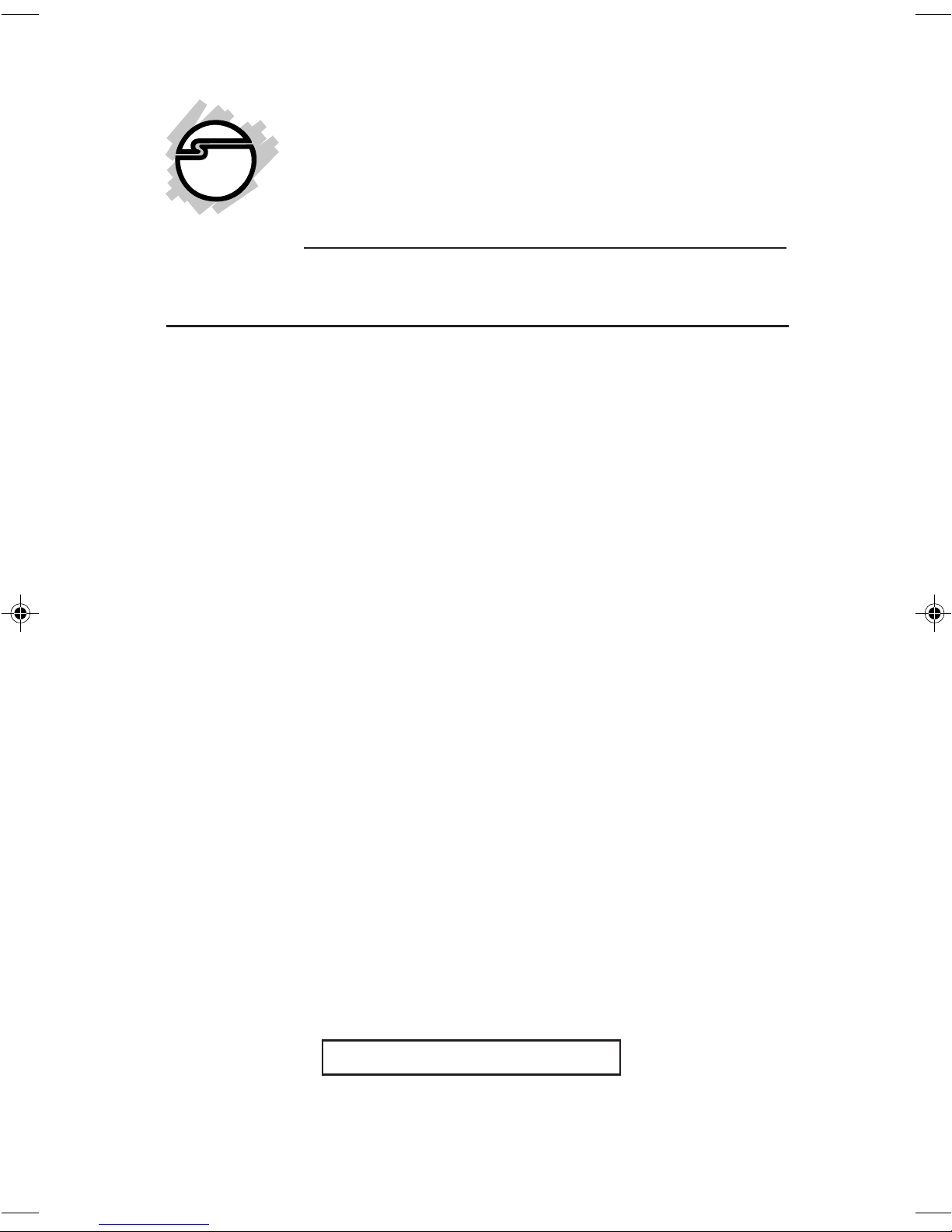
Layout
USB
port
Figure 1: Top Layout
Power
LED
RS-422/485
Signal to
Target Device
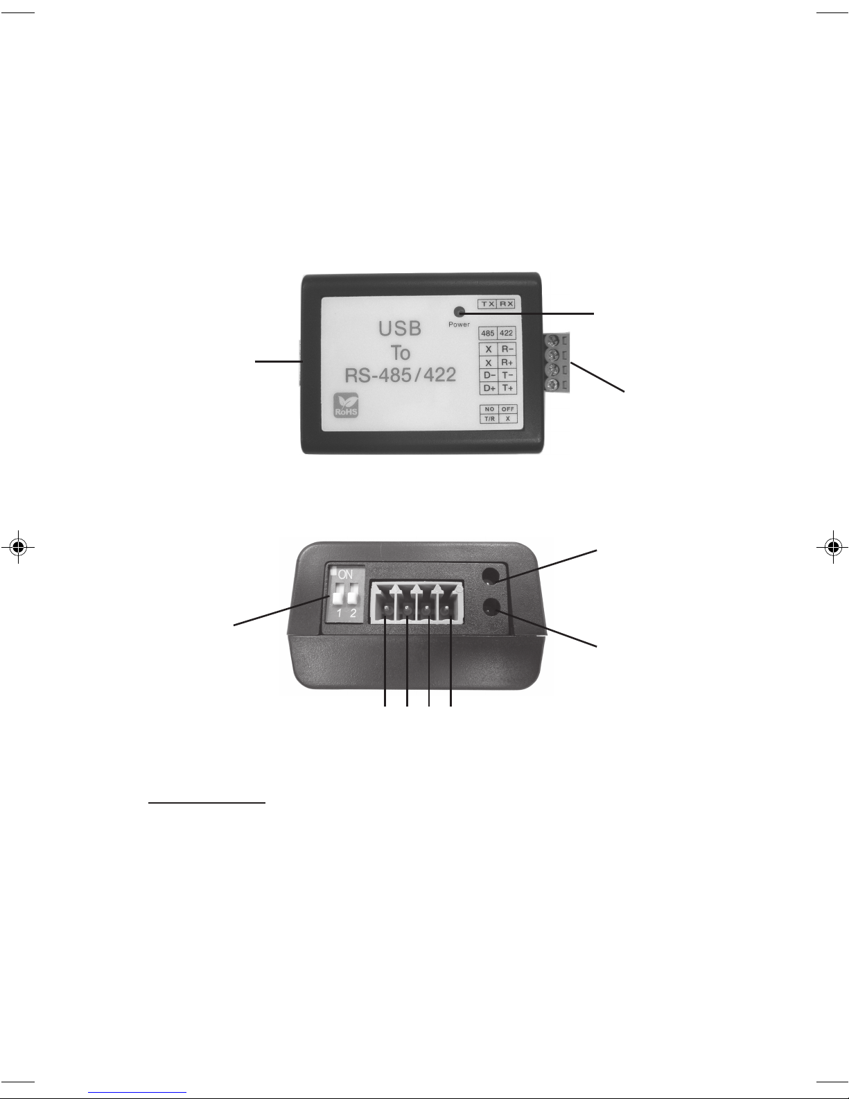
Tx LED
Dip switch
Rx LED
1 2 3 4
Figure 2: Side Layout
DIP Switch
You can change the DIP switch to avoid impedance
mismatched problems.
• For RS-422, move DIP switch 1 down and switch 2
up to ON to enable 120 ohms terminal resistor
• For RS-485, move DIP switch 1 up to ON and switch
2 down to enable 120 ohms terminal resistor
• Move switch 1 & 2 down to disable terminal resistor
2
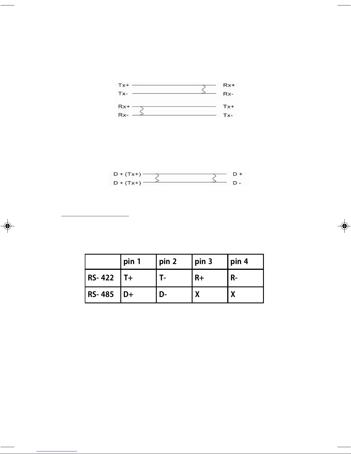
RS-422 or 4-wire RS-485 working model with termination
resistor:
Serial Adapter
Device
2-wire RS-485 working model with termination resistor:
Serial Adapter
Device
Pin Assignment
Refer to Figure 2 for the position of pin 1-4, then refer to
Table 1 below for pin assignment.
Table 1
3
 Loading...