

SIIG RS-422, RS-485, ID-SC0P11-S1, ID-SC0Q11-S1, ID-SC0R11-S1 Quick Installation Manual

USB to RS-422/485
Serial Adapter
Quick Installation Guide
Introduction
The USB to RS-422/485 Serial Adapter provides
additional RS-422/485 serial port(s) to your
systems.
Key Features and Benefits
• Compliant with Universal Serial Bus 2.0
Specification
• Supports serial port data transfer rates up
to 1 Mb/s
• Built in 15KVDC ESD serial interface
protection
• LED indicators for TxD/RxD activities
• Metal housing with wall mount ready
System Requirements
• Desktop or notebook computer with an
available USB port
04-0862A
1
• Windows® 8 (32-/64-bit) / Windows 7 (32/64-bit) / Vista (32-/64-bit) / XP (32-/64bit) / Server 2003 & 2008 (32-/64-bit) /
Server 2008 R2
Package Contents
• USB to RS-422/485 Serial Adapter
• USB cable (Type A/B)
• Termination resistor jumpers (2 for IDSC0P11-S1, 4 for ID-SC0Q11-S1, 8 for IDSC0R11-S1)
• Software CD & quick installation guide
Layout
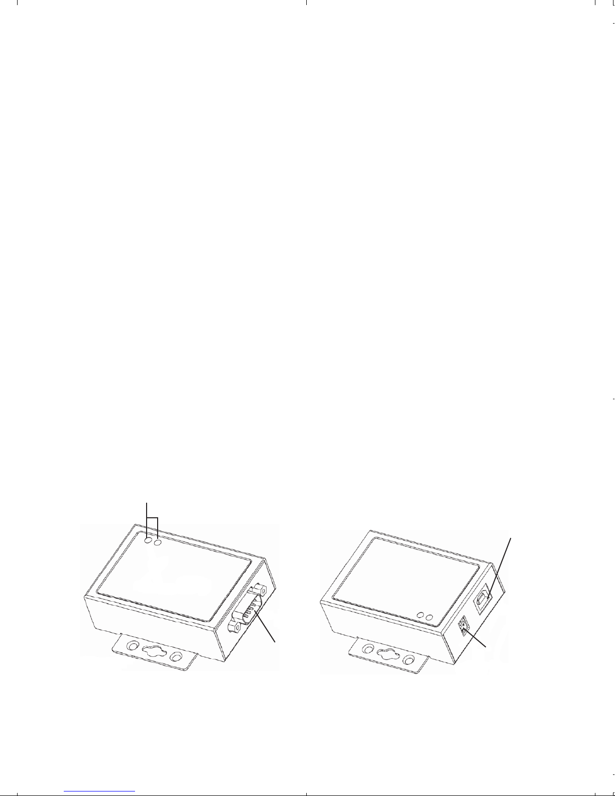
1-Port USB to RS-422/485 Serial Adapter
Status LED
USB Type B
Serial output
DIP switch
Figure 1: ID-SC0P11-S1 Layout
2
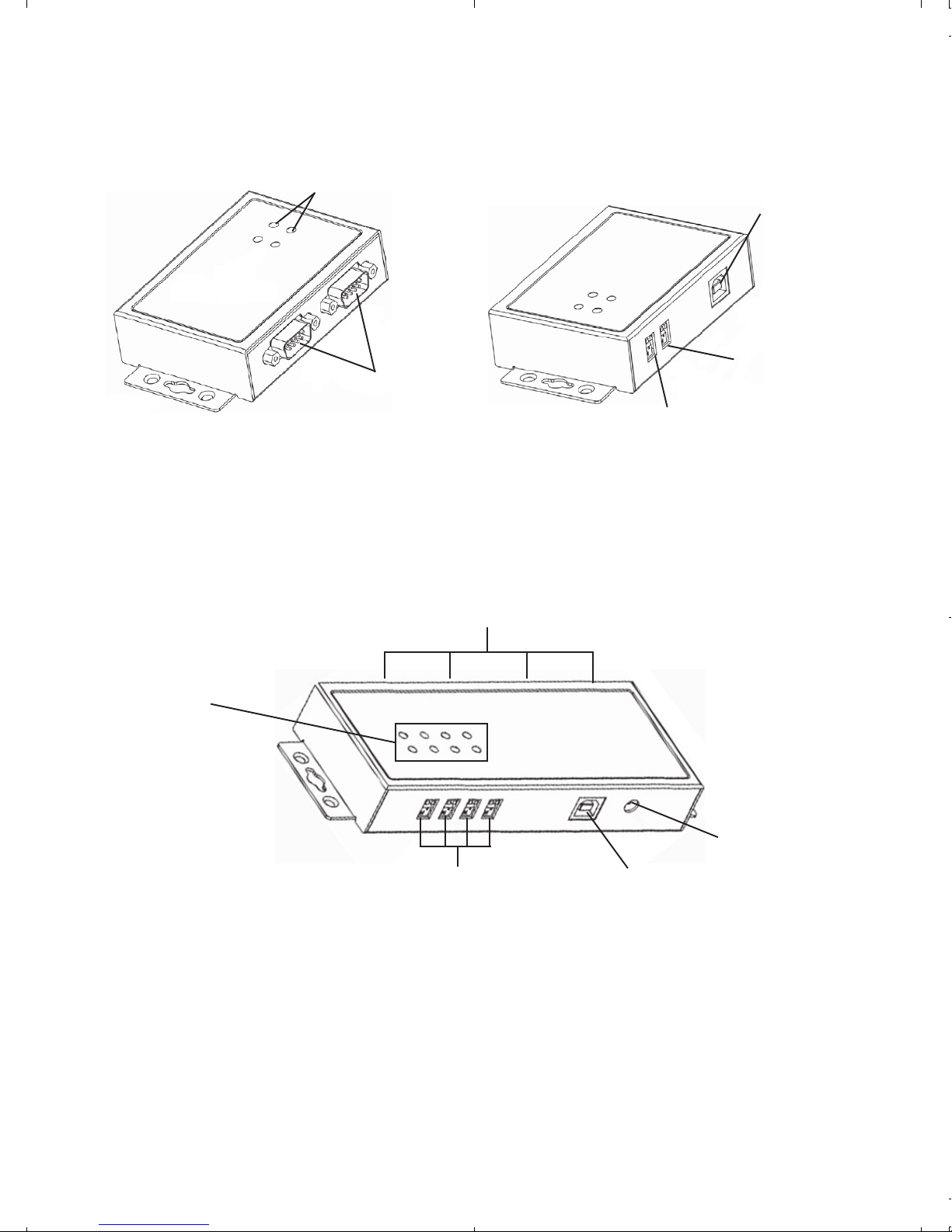
2-Port USB to RS-422/485 Serial Adapter
Status LED
USB Type B
DIP switch
Serial output
DIP switch (P2)
(P1)
Figure 2: ID-SC0Q11-S1 Layout
4-Port USB to RS-422/485 Serial Adapter
Serial output
Status LED
5V power jack
Figure 3: ID-SC0R11-S1 Layout
Status LED
• Tx: Flashing green when sending data
• Rx: Flashing yellow when receiving data
DIP switch (P1-P4)
USB Type B
(optional)
3
• 5V power jack (optional): Connect your
power adapter here (not included).
Note: Most serial devices do not require
additional power through the serial port.
Refer to your serial device's manual for
more information.
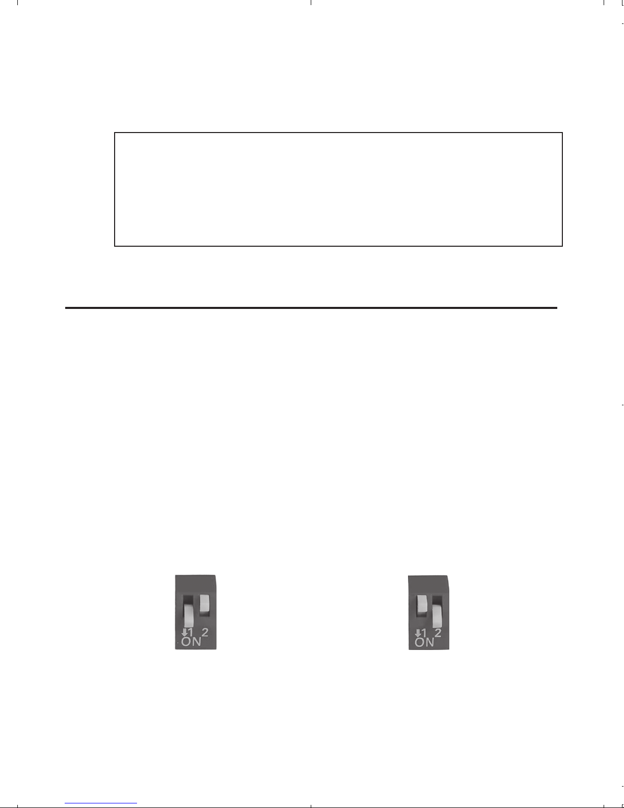
DIP Switch
Auto RS-422/485 (1-ON, 2-OFF)
This is default setting. The COM port will
automatically detect device status and control
the data transmitting or receiving. See Figure 4a.
RS-422 or 4-Wire RS-485 (1-OFF, 2-ON)
Full duplex mode. See Figure 4b.
Auto RS-422/485 RS-422 or 4-Wire RS-485
Figure 4a Figure 4b
4
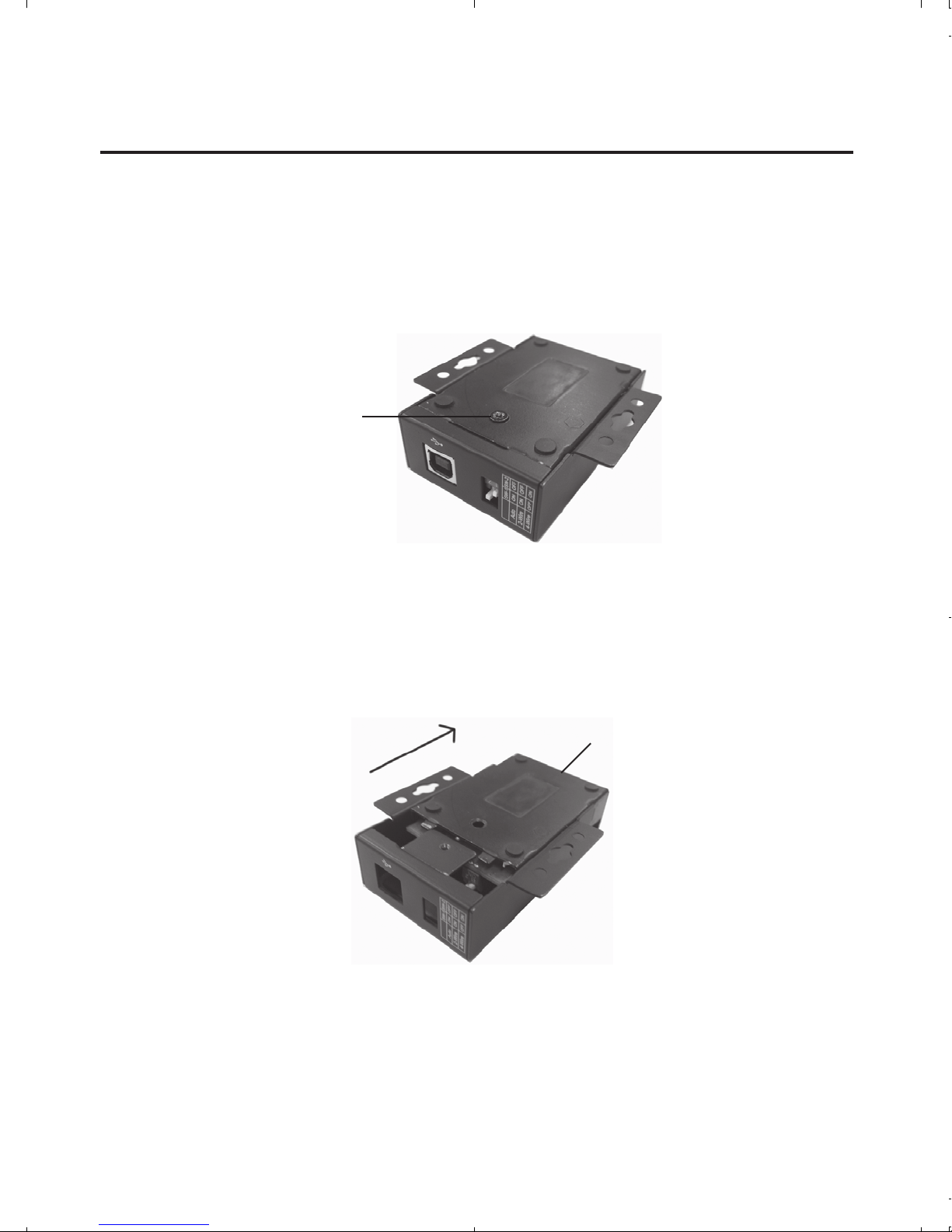
Termination Resistor
Open the cover of the USB to RS-422/485 Serial
Adapter to configure the jumper settings.
1. Unscrew the screw(s) at the bottom of the
Adapter.
Bottom screw
Figure 5
2. Slide the bottom cover in the direction of the
serial output to open.
Serial output
Figure 6
3. Follow the instructions on page 6 to
configure the jumper settings.
5
 Loading...