

Page 1

1
Introducing the Serial Device Server
The Serial Device Server-Dual Port allows to connect a serial
device to a Local Area Network (LAN) or Wide Area
Network (WAN).
Features and Benefits
• Convert serial device (RS-232, RS-422, RS-485) data/
signal into the TCP/IP package data/signal and
send them out with the Ethernet DataStream; or
convert the TCP/IP package data/signal into serial
device data/signal
• Support DHCP client mode, simplifying network
address configuration and management
• Support 10/100 Mbps Ethernet, auto-detected
• ARM-7 Series can be configured as network server
or network client. In the client mode, it can be
installed in network which is protected by NAT
router or firewall, without the need of a real IP
address
• Protected by setup password to prevent intruders
Serial Number Sticker
For future product return or exchange, this serial number
is required. Please keep it for your reference.
04-0483A
Serial Device Server Dual Port
Quick Installation Guide
Page 2
2
Overview
Serial Device Server-Dual Port is designed to make your
serial devices Internet ready instantly. ARM-7 Series of
Serial Device Server-Dual Port makes them the ideal choice
for connecting your RS-232 or RS-422/485 serial devices—
such as PLCs, meters, and sensors to an IP-based Ethernet
LAN, making it possible for your software to access serial
devices anywhere and anytime over a local LAN or the
Internet.
ARM-7 Series converter ensures the compatibility of
network software that uses a standard network API
(Winsock or BSD Sockets) by providing TCP Server Mode,
TCP Client Mode, and UDP Mode. ARM-7 Series’ Virtual
COM driver, software that works with COM port can be
set up to work over a TCP/IP network in no time. This
excellent feature preserves your software investment
and lets you enjoy the benefits of networking your serial
devices instantly.
ARM-7 Series converter supports manual configuration
via the handy web browser console and many protocols
including TCP, IP, UDP, HTTP, DHCP, ICMP, and ARP.
It is the best solution to network your serial devices.
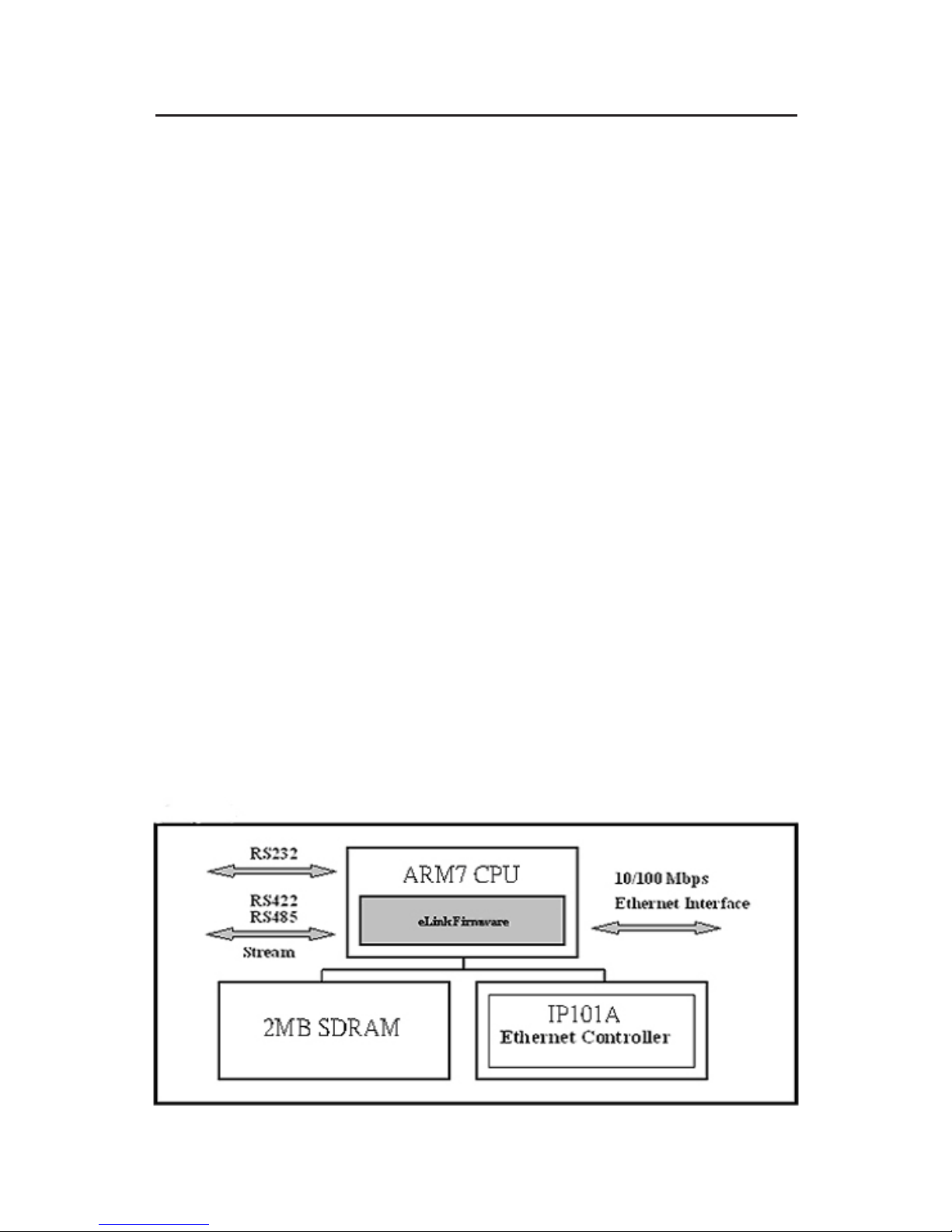
Figure 1: Block Diagram
Page 3
3
Low-cost devices usually are equipped with low speed
processors and limited memories. In reality, they are
neither having the capability nor practicality to manage
complicated network TCP/IP protocols. ARM-7 Series is
a low cost while providing high performance network
solution by converting data stream between network
TCP/IP and popular serial port signals. In stead of
processing TCP/IP packets directly, devices need only
deal with those interface signals, which greatly simplifies
the complexity of TCP/IP network in linkage.
System Requirements
• Pentium II or equivalent PC
• Windows 2000 and above
Package Contents
• Serial Device Server-Dual Port
• Power Adapter and software CD
• Quick Installation Guide
Layout
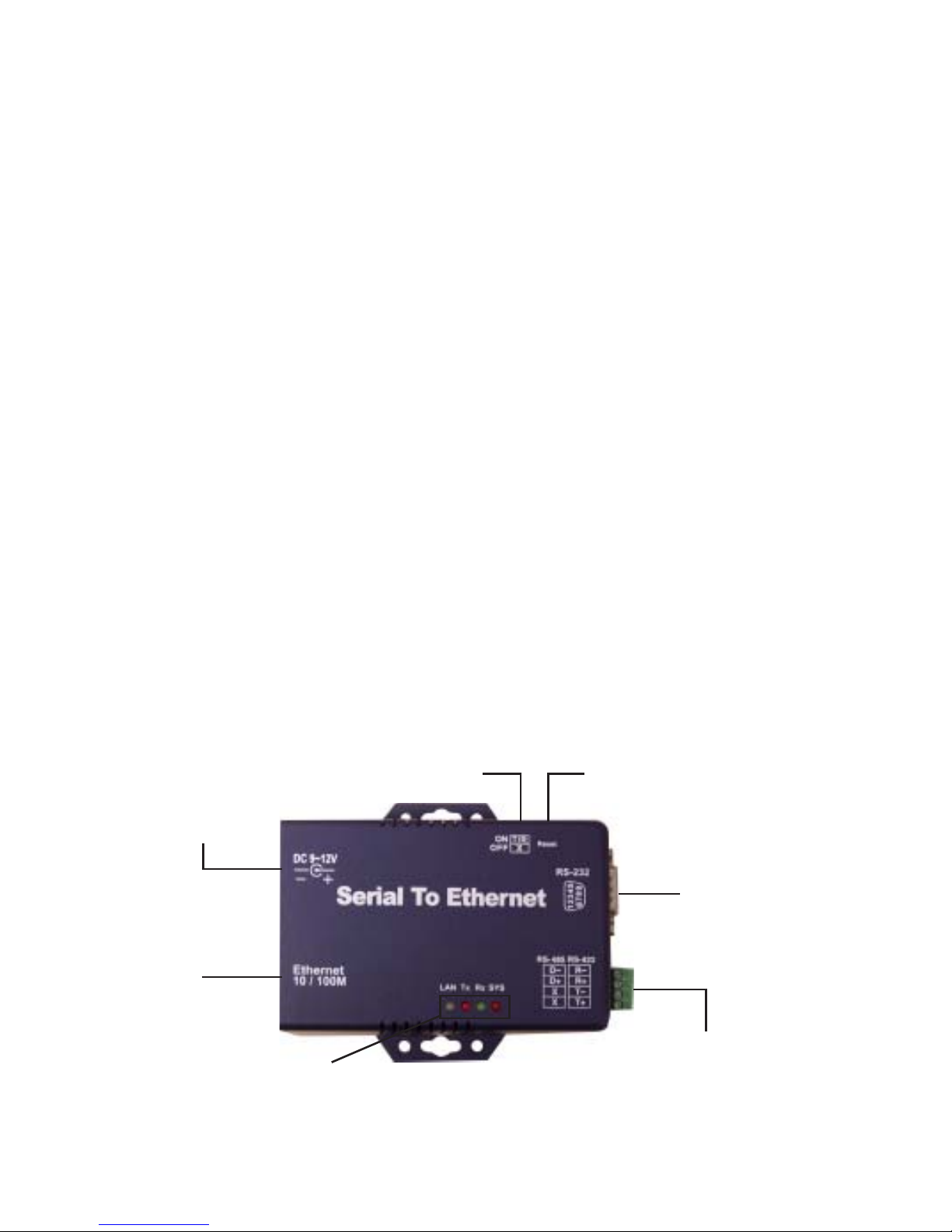
Figure 2: Layout
Reset ButtonRS-422/485 Terminator
DC-In
Power Outlet
LAN
Serial Port
RS-232
Serial Port
RS-485/RS-422
LED Indicators
Page 4

4
Power Supply
The Serial Device Server-Dual Port is powered by a single
9V DC, 500mA (inner positive/outer negative) power
adapter. Connect the power line to the power outlet at the
left side of Serial Device Server-Dual Port and plug the
adapter into a reliable power outlet. If the power is
properly supplied, the SYS red color LED will blink
every second.
LAN Port
The network connection is standard RJ45. Simply connect
it to your network switch or Hub. When the connection is
made, the LAN LED indicator will light up. When data
traffic occurs on the network, red Tx & Rx LED indicator
will blink during data transferring and receiving.
Serial Port of RS-232/RS-422/RS-485
Connect the serial data cable between the converter and
the serial device. Follow the setup procedure to configure
the parameters of the converter.
LED Indicators
• SYS Red LED: Power indicated (when the power is
on the LED will flash every second )
• Rx Green LED: Network signal receiving indicated
(when receive any signal form network the LED will
flash)
• Tx Red LED: Network transmitting indicated (when
transmit any signal to network the LED will flash)
• LAN LED: On-line indicated (when converter link
to LAN the LED will be on) 100M- Green 10M- Red
LED
Page 5
5
Reset Button
Press the Reset button then turn on the power. Wait for
3 seconds. The converter will reset to factory default.
Terminator
There is terminator resistor built in. If the switch 1 & 2 are
set in ON position , 120 Ohm resistor is connected between
the signals.
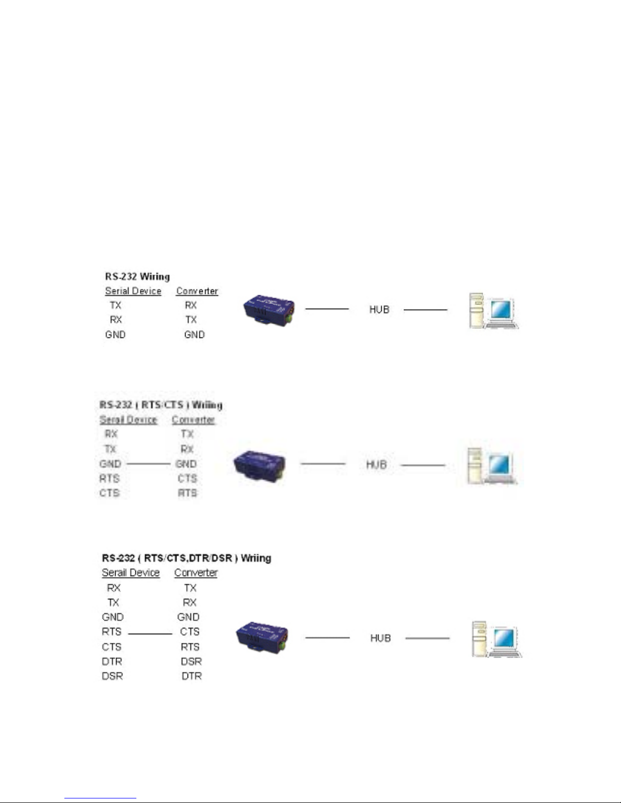
RS 232 Writing Architecture
Page 6
6
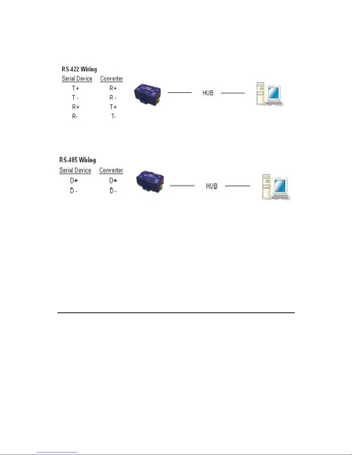
RS-422/RS-485 Wiring Architecture
When you finish the steps mentioned above and the LED
indicators are as shown, the converter is installed correctly.
You can use the setup tool ETM.exe to set the IP Address.
To proceed with the advanced parameters setup, please
use a web browser (IE or Netscape) to continue the
detailed settings.
Converter Configuration
Initial IP Configuration
When setting up your converter for the first time, the first
thing you should d configure the IP address. This section
introduces the method to configure the device server IP
address. For more details about network settings, see
Web Console Configuration in next sub section.
Page 7

7
Device Management Utility
Device Management Utility named ETM.exe which is an
executable program in Windows environment. ETM
Setup Tool is used to detect and setup the installed
converters. It uses UDP broadcast packets to query and
configure converters on the network.
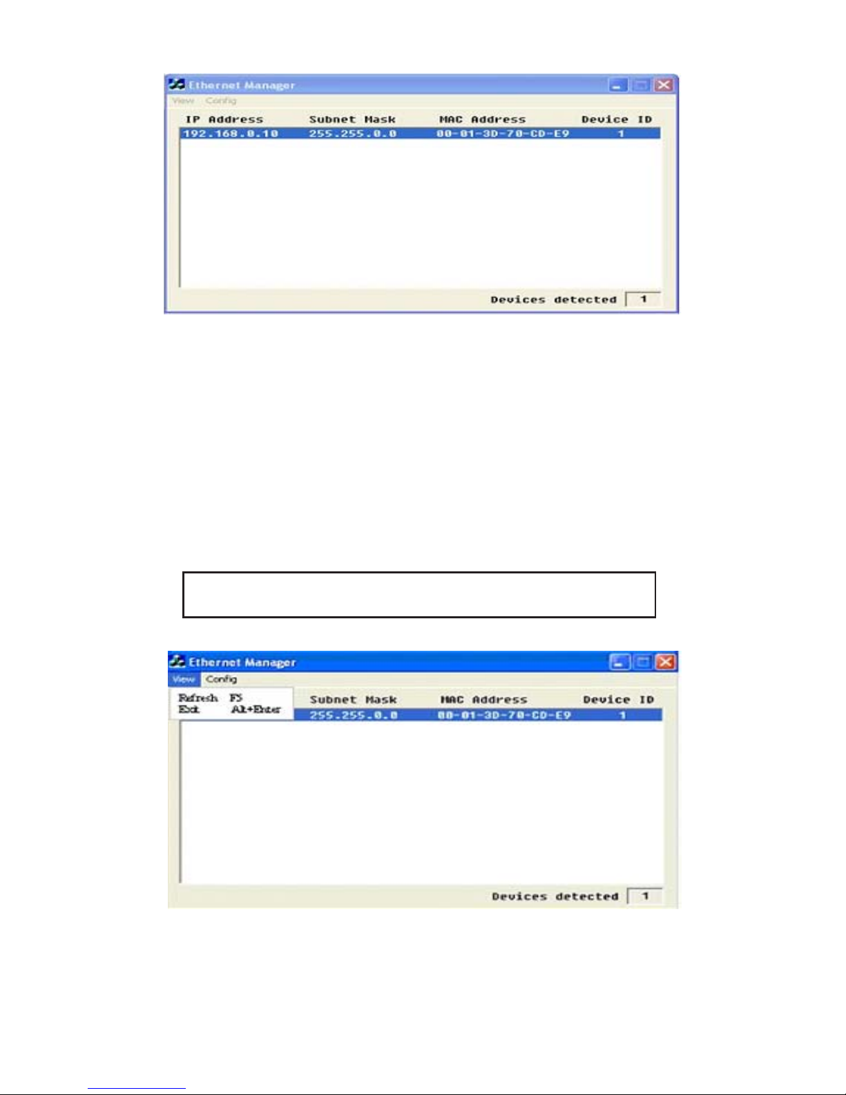
When you activate the tool, it will detect the existence of
the installed converters and display the converters status
such as IP address, Subnet Mask, MAC Address, and
Device ID, see Figure 3 on the next paage.
If your computer OS is Windows XP, WINDOWS
Firewall function is activated and ETM.exe will not detect
the converter’s IP address, therefore, you have to
temporarily disable WINDOWS Firewall function. After
finishing the parameters settings, you can restart
WINDOWS Firewall function.
Due to the nature of broadcast UDP packets, ETM has
following characteristics:
• Broadcast packets aren’t limited by subnet. Even if
the IP address of the converters and the computer
running ETM do not belong to the same subnet, it
still works fine.
• Broadcast packets can not pass routers. ETM can
only be used to monitor devices with computer
running ETM in the same segment of local area
network
Page 8
8
Figure 3
Menu View
Click View , then Refresh or F5 key to refresh the status.
ETM will send another query to get updated information,
see Figure 4.
Click View, then Exit or Alt+4 to exit the program, see
Figure 4.
Note: Always run Refresh after data change.
Figure 4
Page 9
9
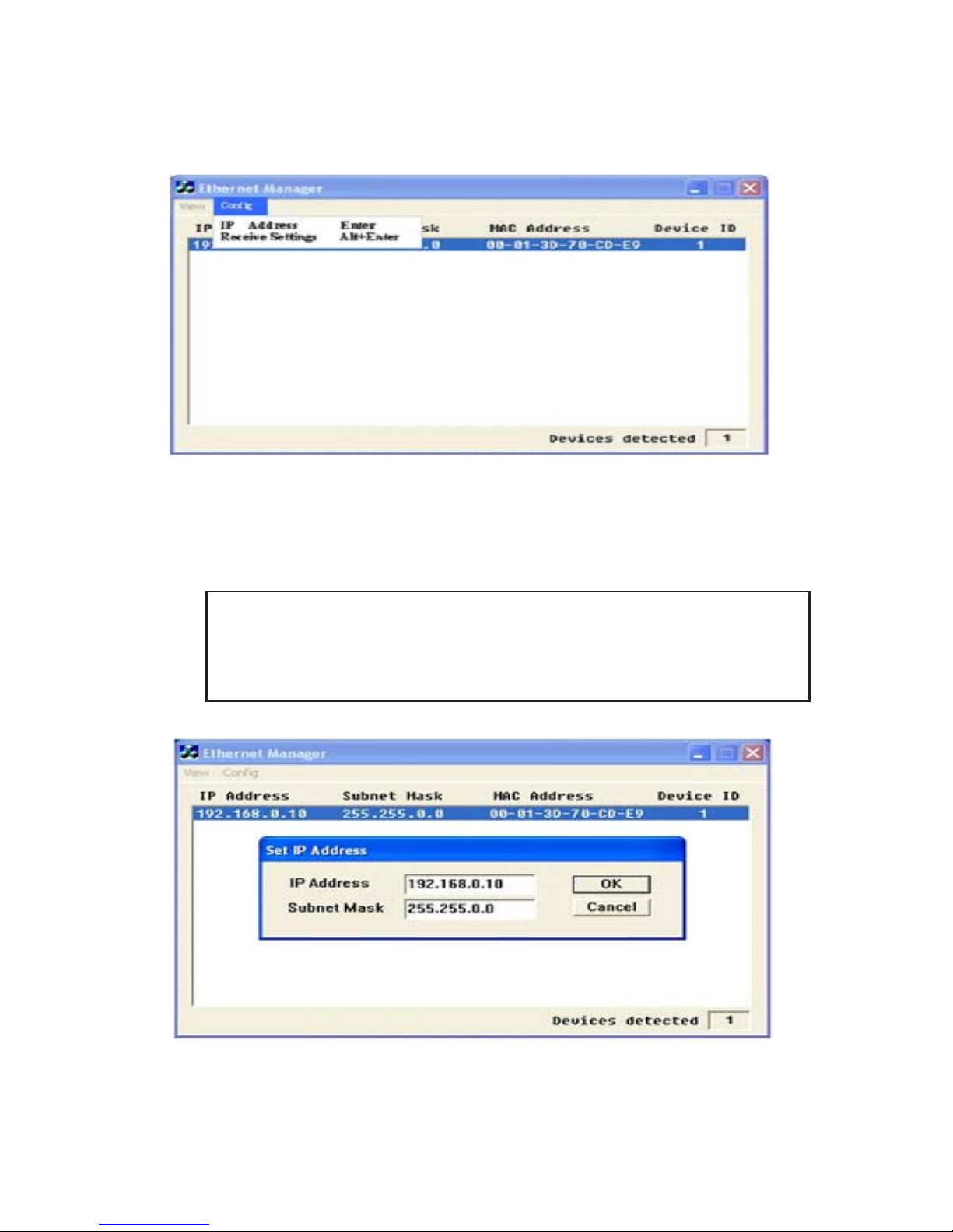
Menu Config
Click Config, then IP Address, see Figure 5.
Figure 5
Press ENTER or select IP Address in the Config menu,
a dialog will be shown see Figure 6.
Note : Because ETM uses broadcast UDP packets,
for the sake of security, it allows configuration only
when device setup password is empty.
Figure 6
Page 10

10
Assign an IP Address with the same Subnet Mask of your
computer, avoiding any IP conflict with other network
devices.
When you press Ok, the IP address will be refreshed in
2-3 seconds, see Figure 7.
Figure 7
Web Console Configuration
In addition to basic IP address and subnet mask, specific
device settings can be set through HTTP protocol with
popular browsers, e.g. Internet Explorer, Netscape, etc.
Setup of the converter is as easy as surfing on WWW, no
special software will be required. Press Alt+Enter or
select Device Settings in the Config menu, will open a
new window in browser to login into the device.
Alternatively, if the IP address of the converter is already
known, you can connect to the converter directly by
providing its IP address in the URL field of browser.
Page 11

11
Controller Status
The Login Page
Setup of Serial Device Server-Dual Port is as easy as surfing
on WWW, no special software is required. Popular
Browsers can easily do the setup process. In the browser
URL field, set the IP address of device directly, To enter
the Controller Status page, please follow the steps below.
• Open your browser. This chapter will use IE as an
example.
• In the browser URL field, type the IP address of the
converter directly and press ENTER. (The IP address
is what you set using the Device Management
Utility).
• The Controller Status page will be shown see
Figure 8.
Figure 8
Page 12

12
Field Description
• System time elapsed
The time elapsed since start of this device in [Day
Hour : Minute : Second] format. This information
can be useful in identifying the reliability of system.
• Firmware version
Converter firmware is identified by date code. This
information will be required in looking for technical
support.
• Serial number
Converter is consisted Type Number (5 digits) and
an unique MAC (Media Access Control) address
used by Ethernet in hex format, 8 digits.
• Password (Setup Login)
This field is the administration password for
authentication. Factory default is empty. However,
it is not recommended to leave it empty in field
operation. If you could not login, it means you have
to key in the password. If you do not know the
password you can turn off the power and then use
any point tip to press Reset button and hold it to
turn on the power. The password will be reset to the
factory default as empty.
Serial Device Server-Dual Port uses the same password
protection mechanism commonly used in Windows
NT or UNIX. If there are more than 3 consecutive
failures in password check during login, the login
function will be disabled for 15 minutes. During
this 15 minutes period, if you supply correct
password, login will not proceed. This prevents
intruders from finding the password by computer
generated program.
Page 13

13
Controller Setup
• The Setup Page
Type the correct password in the Password field
and click the Login button in the Controller Status
page, then the Controller Setup page will appear,
see Figure 9.
Note: If you forget the password or can’t login
successfully, please contact the manufacturer
directly.
Figure 9
Page 14

14
Field Description
• IP Address
Don’t let it conflict with the other devices on the
network.
If DHCP client mode is enabled and there’s a DHCP
server on the network, this field will be assigned by
DHCP server automatically.
• Subnet mask
Subnet mask of the Serial Device Server-Dual Port
converter has connected to. 255.255.255.0 is usually
used for small network, 255.255.0.0 for larger
network, 4 digits separated by a ".".
If your IP address is provided by an ISP or the
network administrator, type the information in
correctly.
If DHCP client mode is enabled and there’s a DHCP
server on the network, this field will be assigned by
DHCP server automatically.
• Gateway address
Gateway or Router IP address. Gateway is a device
which connects local network to external network.
If you need to communicate with other networks or
your device owns a real IP address on the internet,
please use that information and type it correctly. If
there’s no gateway on the network, just leave it as
0.0.0.0.
If DHCP client mode is enabled and there’s a DHCP
server on the network, this field will be assigned by
DHCP server automatically.
Page 15

15
• Network link speed
Ethernet physical link speed. Auto means the speed
is automatically selected by the converter, or specify
10Mbps or 100Mbps to match the speed of the HUB.
• DHCP client
DHCP client mode could be enabled/disabled. If
DHCP is enabled, there should be a DHCP server on
the network.
• Socket port of HTTP setup
Normally, HTTP protocol use TCP port 80 for
communication. If the field is changed to 81, the port
80 will be reserved for user’s own Web.
To enter the browser setup page, http://x.x.x.x:81
should be typed for socket port 81 and http://x.x.x.x
for socket port 80, where x.x.x.x is the converter’s IP
address.
• Destination IP address
The server IP address and socket port would be
connected in TCP Client and UDP mode for a certain
server IP address.
• Destination socket port
The server socket port would be connected in TCP
Client and UDP mode for a certain socket port.
• Connection
The connection can be selected in 2 modes:
Auto function for connect Automatic of converter
Manual function for program control of converter
Page 16

16
• TCP socket inactive timeout input
This feature - inactive timeout - identifies whether
the socket is active or dead. If there is no any data
transferred (send/receive) within the defined
timeout period (1 to 99 minutes), then it is probably
a dead socket, and the socket will be closed
automatically, thus a new connection can be accepted
again. The timeout period can be set by users to fit
different applications.
• Packet mode of serial input
Packet mode could be in enabled/disabled mode.
If packet mode is enabled, the data input from
UART will be deferred until the input buffer is full,
or the converter detects a 10-character packet gap
and no more character arrives. The block waiting
time is extended to avoid the splitting of the
complete packet.
• Device ID
User assigned ID number for the converter. Available
ID is 0 ~ 65535.
• Report device ID when connected
In TCP mode, if this parameter is enabled, every
time when the socket is connected, Serial Device
Server-Dual Port will immediately report its device
ID in the following formats:
Serial #1 nnnnnA[LF][CR]
Serial #2 nnnnnB[LF][CR]
Digital I/O nnnnnC[LF][CR]
The total length is 8 bytes, where nnnnn is a 5-digit
device ID assigned by the user; LF is decimal 10; CR is
decimal 13.
Page 17

17
• Setup password
Administration password used to login the
Controller Setup page. It may be empty or up to 15
characters long.
• Serial Port 1
The first serial port is RS-232.
Socket port
• Port number
A socket port assigned for the serial port. It’s a 16-
bit number, ranging from 1 to 65535. Because the
numbers below 1000 are used for specific purposes
e.g. 80 is for HTTP protocol, we suggest you use
numbers larger than 1000. Generally port number
4660 is used for the serial communication. However
you should specify a different port number for each
serial port.
• Socket type
TCP Server: TCP protocol, passive open, to be
connected from the TCP clients.
TCP Client: TCP protocol, active open, connect to
the TCP server.
UDP Client: UDP protocol, connectionless
• Interface
RS232: TxD, RxD for data stream, no flow control
RS232 (RTS/CTS): TxD, RxD for data stream, RTS/
CTS for flow control RS232 (RTS/CTS, DTR/DSR):
TxD, RxD for data stream, RTS/CTS for flow control.
DTR for socket status, DSR for socket open/close
control.
Page 18

18
• Baud rate, parity, data bits, stop bits
Baud Rate: 300 ~ 230400 bps
Parity: None, Even, Odd
Data Bits: 5, 6, 7, 8
Stop Bit: 1 or 2
• Serial Port 2
The second serial port is RS-422/485.
• Port number
A socket port assigned for the serial port. It’s a 16-
bit number , ranging from 1 to 65535. Because the
numbers below 1000 are used for specific purposes
e.g. 80 is for HTTP protocol, we suggest you use
numbers larger than 1000. Generally port number
4660 is used for the serial communication. However
you should specify a different port number for each
serial port.
• Socket type
TCP Server: TCP protocol, passive open, to be
connected from the TCP clients.
TCP Client: TCP protocol, active open, connect to
the TCP server.
UDP Client: UDP protocol, connectionless
• Interface
RS485 (Half duplex): Half duplex RS-485 interface,
RTS for driver enable/disable RS422 (Full duplex):
Full duplex RS-422 interface
• Baud rate, parity, data bits, stop bits
Baud Rate: 300 ~ 230400 bps
Parity: None, Even, Odd
Data Bits: 5, 6, 7, 8
Stop Bit: 1 or 2
Page 19

19
Controller Updated
Press Update button after you finish the detailed
parameter setting. The converter will save all parameters
into internal non-volatile memory and then reboot, see
Figure 10. It takes about 5 seconds to complete the whole
process, and a new login page will be presented, see
Figure 3.
Figure 10
You can re-login and check if all parameters have been
correctly saved. If everything is ok, you can close the
browser now.
Note : If the domain of the converter is different from
that of the computer running the browser, the login
page won’t appear unless the converter’s Gateway
Address has been correctly set.
Page 20

20
Factory Default Setting
If by chance, you forget the setup password, or have
incorrect settings making the converter inoperable, there
are two ways to reset the setting and the following
procedures can be used to reset all settings to factory
default:
A:
1. Turn off the power of the converter.
2. Press the reset button of the converter.
3. Turn on the power of the converter and wait for
3 seconds.
4. The password will reset to the factory default,
(empty).
B:
1. Log in the web page.
2. Press the reset button of the converter.
3. Select the update button.
4. After Tx & Rx light flashing then unclasp the reset
button.
5. The password will reset to the factory default.
(empty).
Self-Testing
After completing the wiring and parameter setting, we
should verify if the setting is correct or not. This chapter
will introduce how to use a single computer to test if the
converter behaves well.
The operating system can be Windows 95, 98, ME, XP,
2000. The Hyper Terminal utility should be installed on
your PC see Figure 12. It can be found in your Windows
installation CD.
Page 21

21
The wiring architecture is similar to RS-232 Wiring in
page 5, and the serial device is replaced by the PC’s COM
1. The same PC also plays the roll of the Remote Host.
Figure 11
Hyper Terminal for TCP/IP WinSock
Initiate Hyper Terminal from the Start Menu in Windows,
see Figure 12, give a terminal name, choose an icon, and
press OK button, see Figure 13.
Figure 12
Page 22

22
Figure 13
Select TCP/IP(Winsock) option at the Connect using:
field, see Figure 14.
Figure 14
Page 23

23
After OK button is pressed, see Figure 15 appears. Enter
the converter’s IP address e.g. 192.168.0.10 at the Host
address: field, and the Socket port number set for the
Serial Port 1 at the Port number: field (e.g 4660). (The
Socket type of the Serial Port 1 should be TCP Server.)
Figure 15
After OK button is pressed, see Figure 14 appears. If the
Hyper Terminal connects with the converter successfully,
the time clock at the left lower corner Connected hh:mm:ss
will start counting.
Figure 16
Page 24

24
Hyper Terminal for COM Port
Initiate another Hyper Terminal as a COM Port Terminal,
(see Figure 14, select COM 1 or other COM port instead
of TCP/IP Winsock. Set the COM port Properties to be
the same as those set for the Serial Port of the converter
(9600.N.8.1).
Figure 17
Data Transmission
When all steps described above are finished, type any
characters on the COM Port Terminal and check if the
typed characters are also displayed on the TCP/IP
Winsock Terminal. Alternatively, check if the characters
typed on the TCP/IP Winsock Terminal are also
displayed on the COM Port Terminal. If yes, then all
settings are correct and the converter is operating properly.
Page 25

25
Pin out and Cable Wiring
DC Power outlet
RJ-45 Pin Assignment
RS-232 Pin Assignment
The pin assignment scheme for a 9-pin male connector on
a DTE is given below.
Pin 1: DCD Pin 6: DSR
Pin 2: RXD Pin 7: RTS
Pin 3: TXD Pin 8: CTS
Pin 4: DTR Pin 9: X
Pin 5: GND
Page 26

26
RS-422 Pin Assignment
The pin assignment scheme for a 4-pin RS-422 is given
below.
1 2 3 4
PIN 1: R- Pin 2: R+ PIN 3: T- PIN 4: T+
Page 27

27
Technical Support and Warranty
QUESTIONS? SIIG’s Online Support has answers! Simply visit our
web site at www.siig.com and click Support. Our online support
database is updated daily with new drivers and solutions. Answers
to your questions could be just a few clicks away. You can also submit
questions online and a technical support analysts will promptly
respond.
SIIG offers a 5-year manufacturer warranty with this product. Please
see our web site for more warranty details. If you encounter any
problems with this product, please follow the procedures below.
A) If it is within the store's return policy period, please return the
product to the store where you purchased from.
B) If your purchase has passed the store's return policy period, please
follow these steps to have the product repaired or replaced.
Step 1: Submit your RMA request.
Go to www.siig.com, click Support, then RMA to submit a
request to SIIG RMA. If the product is determined to be
defective, an RMA number will be issued.
Step 2: After obtaining an RMA number, ship the product.
• Properly pack the product for shipping. All software, cable(s)
and any other accessories that came with the original package
must be included.
• Clearly write your RMA number on the top of the returned
package. SIIG will refuse to accept any shipping package, and
will not be responsible for a product returned without an
RMA number posted on the outside of the shipping carton.
• You are responsible for the cost of shipping. Ship the product
to the following address:
SIIG, Inc.
6078 Stewart Avenue
Fremont, CA 94538-3152, USA
RMA #:
• SIIG will ship the repaired or replaced product via Ground
in the U.S. and International Economy outside of the U.S. at
no cost to the customer.
Page 28

Serial Device Server - Dual Port is a trademark of SIIG, Inc. SIIG and the SIIG logo are registered
trademarks of SIIG, Inc. Microsoft, Windows and Windows Vista are either registered trademarks or
trademarks of Microsoft Corporation in the United States and/or other countries. Pentium is a
registered trademark of Intel Corporation. Other names used in this publication are for identification
only and may be trademarks of their respective companies.
June, 2008 Copyright © 2008 by SIIG, Inc. All rights reserved.
About SIIG, Inc.
Founded in 1985, SIIG, Inc. is a leading computer upgrade manufacturer
of I/O connectivity products, including PCIe, PCI & ISA serial and
parallel ports, USB, Serial ATA & UltraATA controllers, FireWire
(1394a/b), networking, sound cards, and other accessories. SIIG is the
premier one-stop source of upgrades.
SIIG products offer comprehensive user manuals, many user-friendly
features, and are backed by an extensive manufacturer warranty.
High-quality control standards are evident by the overall ease of
installation and compatibility of our products, as well as one of the
lowest defective return rates in the industry. SIIG products can be
found in computer retail stores, mail order catalogs, through major
distributors, system integrators, and VARs in the Americas and the
UK, and through e-commerce sites.
PRODUCT NAME
Serial Device Server - Dual Port
FCC RULES: TESTED TO COMPLY WITH FCC PART 15, CLASS
B OPERATING ENVIRONMENT: FOR HOME OR OFFICE USE
FCC COMPLIANCE STATEMENT:
This device complies with part 15 of the FCC Rules. Operation is
subject to the following two conditions: (1) This device may not cause
harmful interference, and (2) this device must accept any interference
received, including interference that may cause undesired operation.
THE PARTY RESPONSIBLE FOR PRODUCT COMPLIANCE
SIIG, Inc.
6078 Stewart Avenue
Fremont, CA 94538-3152, USA
 Loading...