

Page 1
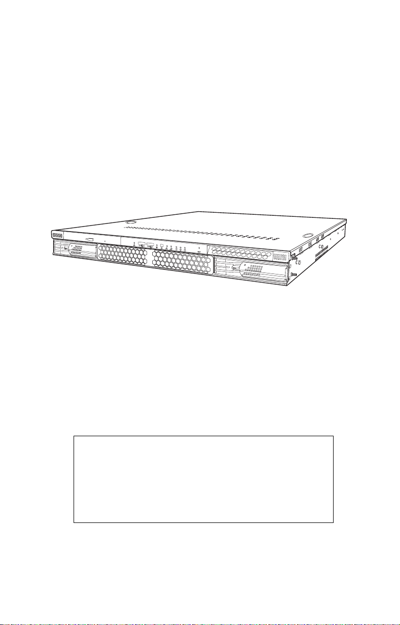
Transport GX21
B5350
User’s Manual
WARNING!
This product should be serviced only by qualified service
engineers. Do not remove the chassis cover or attempt to
service this product unless you are qualified to do so. Once
the chassis cover is removed, there is a risk of electric
shock that could lead to serious injury or death.
Page 2

Copyright
This publication, including all photographs, illustrations, and software, is protected under international copyright laws, with all rights
reserved. Neither this manual, nor any material contained herein,
may be reproduced without written consent of the manufacturer-.
Copyright 2003-4
Version 1.00
Disclaimer
Information contained in this document is furnished by TYAN computer Corporation and has been reviewed for accuracy and reliability
prior to printing. TYAN assumes no liability whatsoever, and disclaims any express or implied warranty, relating to sale and/or use of
TYAN products including liability or warranties relating to fitness for
a particular purpose or merchantability. TYAN retains the right to
make changes to product descriptions and/or specifications at any
time, without notice. In no event will TYAN be held liable for any
direct or indirect, incidental or consequential damage, loss of use,
loss of data or other malady resulting from errors or inaccuracies of
information contained in this document.
Trademark recognition
All registered and unregistered trademarks and company names
contained in this manual are property of their respective owners
including, but not limited to the following.
TYAN, TYAN Tiger i7501R (5350), and Transport GX21 are trademarks of TYAN Computer Corporation.
Intel, Xeon, and combinations thereof are trademarks of Intel Corporation.
Phoenix, PhoenixBIOS, and combinations thereof are trademarks of
Phoenix Technologies Ltd.
Microsoft Windows is a trademark of Microsoft Corporation.
IBM, PC, AT and PS/2 are trademarks of IBM Corporation.
Winbond is a trademark of Winbond Electronics Corporation.
Portable Document Format (PDF) is a trademark of Adobe Corporation.
Preface
Page 3

Federal Communications Commission
Notice for the USA Compliance Information State-
ment (Declaration of Conformity Procedure) DoC
FCC Part 15: This device complies with part 15 of the
FCC Rules
Operation is subject to the following conditions:
1) This device may not cause harmful interference, and
2) This device must accept any interference received including interference that may cause undesired operation. If this equipment does
cause harmful interference to radio or television reception, which
can be determined by turning the equipment off and on, the user is
encouraged to try one or more of the following measures:
• Reorient or relocate the receiving antenna.
• Increase the separation between the equipment and the
receiver.
• Plug the equipment into an outlet on a circuit different from
that of the receiver.
Consult the dealer on an experienced radio/television technician for
help.
Notice for Canada
This apparatus complies with the Class B limits for radio interference
as specified in the Canadian Department of Communications Radio
Interference Regulations. (Cet appareil est conforme aux norms de
Classe B d’interference radio tel que specifie par le Ministere Canadien des Communications dans les reglements d’ineteference
radio.)
Notice for Europe (CE Mark) This product is in conformity
with the Council Directive 89/336/EEC, 92/31/EEC
(EMC).
CAUTION: Lithium battery included with this board. Do not puncture,
mutilate, or dispose of battery in fire. Danger of explosion if battery
is incorrectly replaced. Replace only with the same or equivalent
type recommended by manufacturer. Dispose of used battery
according to manufacturer instructions and in accordance with your
local regulations.
ii
Page 4

About this manual
This manual provides you with instructions on installing your Transport GX21 (B5350), and consists of the following sections
Chapter 1:
Provides an introduction to the Transport GX21 (B5350) bare bones,
packing list, describes the external components, gives tables of key
components, and provides block diagrams of the system.
Chapter 2:
Covers procedures on installing the CPUs, memory modules,
optional PCI card, and hard drives.
Chapter 3:
Covers removal and replacement procedures for pre-installed components.
Appendix:
Provides detailed specifications, maintenance and troubleshooting
procedures, an explanation of BIOS and technical diagrams.
iii
Page 5

Safety information
Before installing and using the Transport GX21 , take note of the following precautions:
• Read all instructions carefully.
• Do not place the unit on an unstable surface, cart or stand.
• Do not block the slots or openings on the unit which are
provided for ventilation.
• Only use the power source indicated on the marking label.
If you are not sure, contact the power company.
• The unit uses a three-wire grounded cable, which is sup-
plied with a third pin to ground the unit and prevent electric
shock. Do not defeat the purpose of this pin. If your outlet
does not support this type of plug, contact an electrician to
replace the obsolete outlet.
• Do not place anything on the power cord. Place the power
cord where it will not be stepped on.
• Follow all warnings and cautions in this manual and on the
unit case.
• Do not push objects in the ventilation slots as they may
touch high voltage components and result in shock and
damage to the components.
• When replacing parts, ensure that you use parts specified
by the manufacturer.
• When service or repairs have been carried out, perform
routine safety checks to verify that the system is operating
correctly.
• Avoid using the system near water, in direct sunlight, or
near a heating device.
• Cover the unit when not in use.
iv
Page 6

Contents
Overview
About the Transport GX21 (B5350) . . . . . . . . . . . . . . . . . . . . . . . . . . . . 1
Product models. . . . . . . . . . . . . . . . . . . . . . . . . . . . . . . . . . . . . . . . . . . . . 1
Features . . . . . . . . . . . . . . . . . . . . . . . . . . . . . . . . . . . . . . . . . . . . . . . . . . 2
B5350G21S2H specifications . . . . . . . . . . . . . . . . . . . . . . . . . . . . . . . 2
Box contents . . . . . . . . . . . . . . . . . . . . . . . . . . . . . . . . . . . . . . . . . . . .3
Accessories . . . . . . . . . . . . . . . . . . . . . . . . . . . . . . . . . . . . . . . . . . . . . 4
Opening the box. . . . . . . . . . . . . . . . . . . . . . . . . . . . . . . . . . . . . . . . . .5
About the product. . . . . . . . . . . . . . . . . . . . . . . . . . . . . . . . . . . . . . . . . . .6
System front view and front panel. . . . . . . . . . . . . . . . . . . . . . . . . . . .6
System rear view . . . . . . . . . . . . . . . . . . . . . . . . . . . . . . . . . . . . . . . . . 6
System internal views . . . . . . . . . . . . . . . . . . . . . . . . . . . . . . . . . . . . .7
Setting up
Before you begin . . . . . . . . . . . . . . . . . . . . . . . . . . . . . . . . . . . . . . . . . . .9
Work area. . . . . . . . . . . . . . . . . . . . . . . . . . . . . . . . . . . . . . . . . . . . . . . 9
Tools . . . . . . . . . . . . . . . . . . . . . . . . . . . . . . . . . . . . . . . . . . . . . . . . . .9
Precautions. . . . . . . . . . . . . . . . . . . . . . . . . . . . . . . . . . . . . . . . . . . . .10
Installing motherboard components . . . . . . . . . . . . . . . . . . . . . . . . . . . .11
Removing the chassis cover. . . . . . . . . . . . . . . . . . . . . . . . . . . . . . . .11
Installing CPUs . . . . . . . . . . . . . . . . . . . . . . . . . . . . . . . . . . . . . . . . . 12
Installing memory . . . . . . . . . . . . . . . . . . . . . . . . . . . . . . . . . . . . . . .15
Installing a PCI card . . . . . . . . . . . . . . . . . . . . . . . . . . . . . . . . . . . . . 16
Installing a hard drive. . . . . . . . . . . . . . . . . . . . . . . . . . . . . . . . . . . . . . .20
Installing an external S-ATA hard drive . . . . . . . . . . . . . . . . . . . . . .20
Rack mounting . . . . . . . . . . . . . . . . . . . . . . . . . . . . . . . . . . . . . . . . . . . .23
Replacing installed components
Introduction . . . . . . . . . . . . . . . . . . . . . . . . . . . . . . . . . . . . . . . . . . . . . .27
Replacing motherboard components . . . . . . . . . . . . . . . . . . . . . . . . . . .27
Disconnecting all motherboard cables. . . . . . . . . . . . . . . . . . . . . . . .27
Replacing the motherboard . . . . . . . . . . . . . . . . . . . . . . . . . . . . . . . . 30
Replacing the CD-ROM drive . . . . . . . . . . . . . . . . . . . . . . . . . . . . . . . .31
Replacing the LED control board . . . . . . . . . . . . . . . . . . . . . . . . . . . . .32
Replacing the storage backplane . . . . . . . . . . . . . . . . . . . . . . . . . . . . . . 33
Replacing the power supply . . . . . . . . . . . . . . . . . . . . . . . . . . . . . . . . . . 36
Replacing the cooling fans . . . . . . . . . . . . . . . . . . . . . . . . . . . . . . . . . . . 37
Appendix
BIOS. . . . . . . . . . . . . . . . . . . . . . . . . . . . . . . . . . . . . . . . . . . . . . . . . . . . 39
Technical support . . . . . . . . . . . . . . . . . . . . . . . . . . . . . . . . . . . . . . . . . .63
Page 7
1.1 About the Transport GX21 (B5350)
Chapter 1: Overview
1.1 About the Transport GX21 (B5350)
Congratulations on your purchase of the Transport GX21
(B5350), rack mountable, barebone system for Intel® Xeon™
processor. The Transport GX21 (B5350) uses an advanced
Intel chipset for optimum performance and reliability. The
add-on S-ATA storage controller provides great flexibility and
is combined with Gigabit Ethernet ports to provide powerful
computing capacity and optimal I/O bandwidth for the most
demanding of enterprises.
The rugged, industry standard 19-inch, rack mountable
design contains up to 2 HDD bays, 1 slim CD-ROM bay
option, making it both flexible and practical.
1.2 Product models
Model HDD
B5350G21S2H 2 removable
HDD bays
Chapter 1: Overview 1
Hot Swap
Support
Yes 2 po r t S-
HDD
Backplane
ATA
SKU Type
Standard SKU
Page 8

1.3 Features
1.3 Features
1.3.1 B5350G21S2H specifications
Enclosure
• Industry standard, 19” rack mountable, 1U chassis
• 2 hot swappable HDDs
• 1 slim CD-ROM bay
• 21.5 x 17 x 1.73 inch (546 x 432 x 44
mm)
Processors
• Dual mPGA604pin ZIF sockets
• Single or dual Intel® Xeon™
(Nacona) processor
• 800 MHz FSB
Chipset
• Intel® Lindhurst-VS (E7320) MCH
• Intel Hance Rapids (6300ESB)
Southbridge
• SMSC DME1737 LPC I/O chip
• Analog Devices ADM1027 hardware
monitoring IC
Memory
• Dual channels, (8) DIMM sockets
• Support for up to (6) DDR333 or (8)
DDR266
• Up to 16 GB of registered DDR
• Support for ECC type memory modules
Expansion slots
• (1) 64-bit, 66 MHz PCI-X slot on
riser card
Back I/O ports
• Stacked PS/2 mouse and keyboard
ports
• 2 USB 2.0 ports
• 1 9-pin UART serial port
• 2 RJ-45 LAN ports
• 1 VGA port
Front panel
• 2 USB 2.0 ports
• HDD activity, Warning/Fail, LAN
activity, and power LEDs
• Power and reset switches
Storage
• Dual channel IDE (CD-ROM)
• Integrated Serial ATA (6300ESB),
support for 2 SATA ports, RAID 0,1
• Support for up to 2 hot-swappable
SATA 1.0 HDD
Cooling
• 4 cooling fans (40 x 40 x 56 mm)
• 1 cooling fans (40 x 40 x 28 mm)
• 2 passive CPU heatsinks
Motherboard
• Tyan Tiger i7510 S5350 motherboard
• ATX form factor
• Phoenix BIOS on 8 Mb LPC flash
ROM
Networking
• 2 Gigabit Ethernet ports (Broadcom
BCM5721PCI-E GbE LAN controller connected MCH), with teaming
feature support
Power supply
• EPS 12V, 1U, 500W with PFC
Video
• ATI® Rage™ XL PCI Graphics controller
• 8 MB frame buffer video memory
Regulatory
• FCC class B (declaration of
conformity)
• CE (declaration of conformity)
2 Chapter 1: Overview
Page 9
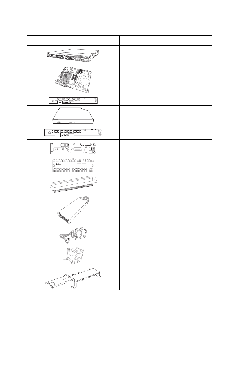
1.3.2 Box contents
Diagram Component
1.3 Features
1U chassis, 2 external HDD bays
Tyan S5350 system board (preinstalled)
2
J1
1
41
J3
40
39
1
J4
Slim CD-ROM adapter
24x slim CD-ROM drive (preinstalled)
2
J1
1
41
J3
40 94V-0
39
1
CORER1.PCB MADE TAIWAN
J4
Slim FDD adapter
S-ATA backplane and holding
bracket (pre-installed)
LED control board (pre-installed)
64-bit riser card (pre-installed)
EPS 12V 500W PSU (pre-installed)
15,500 rpm cooling fan (4 pcs -
40 x 40 x 56 mm)
15,000 rpm cooling fan (1 pcs -
40 x 40 x 28 mm)
Fan holding bar
Chapter 1: Overview 3
Page 10
1.3 Features
h
ttp://w
w
w
.t
y
a
n
.c
o
m
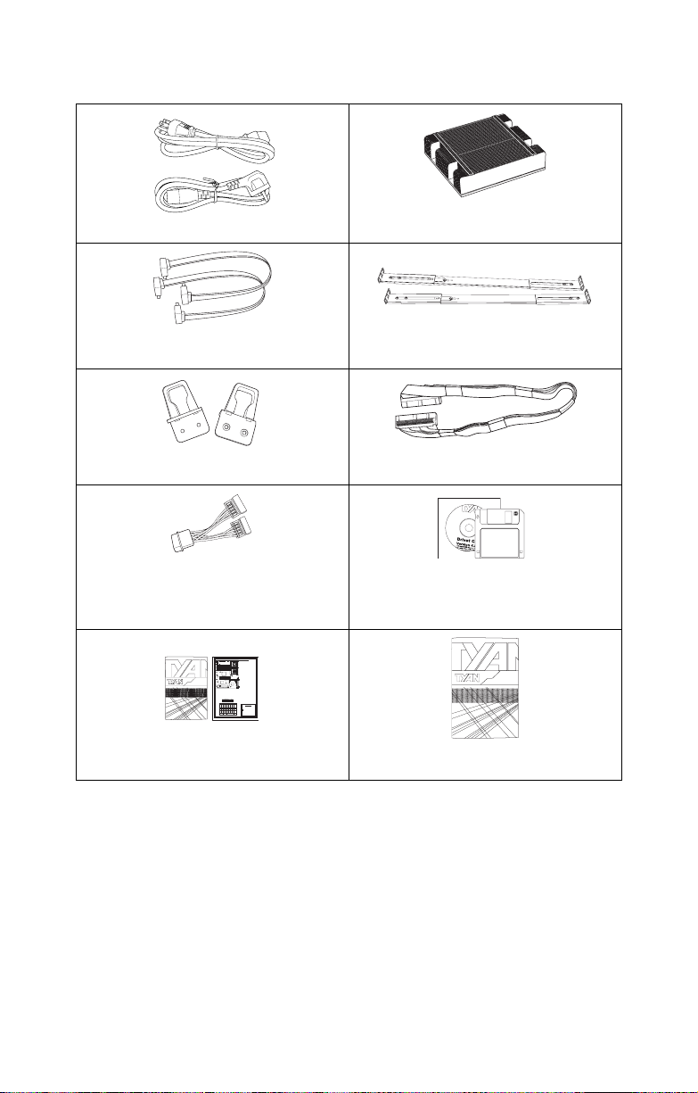
1.3.3 Accessories
Power cords (US/German)
2 x CPU heatsinks
P/N 343734800001
2 x S-ATA cables, motherboard to
backplane
2 x mounting ears
S-ATA power riser cable
Tiger i7501R S2735 Board Parts and Jumpers
1
J16 Force 400MHz FSB instead
J4
FAN1
KB(Bottom)
KB / MS
CPU1_FAN
J4J3
of 533MHz FSB Header
Mouse(Top)
J5
USB (Bottom)
Close: Force 400 MHz FSB
LAN1 (Top) Optional
USB1
(4x 100MHz)
FAN3
CPU
CPU1
1
Open: 533MHz FSB
DIMMA_DIMM3
J7
(COM1)
(4x 133MHz)
DIMMA_DIMM2
J21 PCI-X A (PCI1) Speed
DIMMA_DIMM1
1-2 Close: 100MHz
DIMMB_DIMM3
J11
2-3 Close: 133MHz (Default)
DIMMB_DIMM3
(VGA)
J22 10/100 Ethernet LAN1 LED
DIMMB_DIMM1
(82551) Header
J14
BT1
CPU
CPU
CPU2
LAN3
Pin1: Yellow+
Pin2: Yellow-
J15
LAN2
Intel
Pin3: Green+; Pin4: Green-
S2735
E7501
J23 Gigabit Ethernet LAN2 (J15)
J16
LED Header
1
High Performance Motherboard
User's Manual
FAN4
Intel
CPU2_FAN
Pin1: Yellow+
82546EB
PCI1
FAN5
Pin2: Yellow-
FAN9
PCI2
Pin3: Green+; Pin4: Green-
J22
J26 SO_DIMM
1
J24 Gigabit Ethernet LAN3 (J14)
11
1
J25
JP1
J21
B5350
LED Header
J23
1
J43
11
1
1
Intel
Pin1: Yellow+
P64H2
J24
82551
ATI
GX21
Pin2: Yellow-
RAGE XL
Pin3: Green+; Pin4: Green-
Intel
PRI-IDE J15
SEC-IDE J13
ICH5R
PCI3
J25 Buzzer (System Speaker)
SMDC J29
Winbond
J32
BIOS
W83627HF
Pin1: Vcc, Pin2 & 3: NC
1
FAN6
J31
1
PCI4
Pin4: Speak
USB2
1
SATA2
SATA1
1
J34
J36
MMOS J33
J26 SO-DIMM (Compatible with
FAN2
FDDJ37 LPT1
FAN7
J39
1
1
111
FRONT PANEL
COM2
Tyan M7902 SCSI RAID Card)
FAN8
FAN1
CPU1_FAN
J29 SMDC (System Management
FAN4
CPU2_FAN
Daughter Card) Connector
FAN2 / FAN3 / FAN5 / FAN6 /
Chassis FAN
J31 Hard Disk Activity LED
FAN7 / FAN8 / FAN9
External Input
J33 CMOS Clear
Pin 1-2 Close: Normal (Default)
Pin 2-3 Close: Clear CMOS
J34 Front USB Header (USB2)
(via an optional cable)
J39 Front Panel Connector
J36 COM2 port (via a cable)
18
2
J43 PCI-X B (PC12) Speed
1-2 Close: 100MHz (Default)
17
1
2-3 Close: 133MHz
PWR_LEDPWRER SLEEP INTRU
Power Supply
The Tiger i7501R S2735 is EPS12V
PWR+
GND
SLEEP+
GNDNCNC
INTRU-
PWR_LED+
PWR_LED+
compatible.
24 6 8 10 1214 1618
1
7
9
17
3
5
111315
2 power connectors: EPS12V
(24-pin) + EPS12V (8-pin)
+5V
GND
GND
IRTX
IRRX
power connectors
INTRU+
RESET+
HD_LED-
HD_LED+
Check User's Manual for details
HD-LED RESET INFRARED INTRU
OSE P/N:12-0012-355C
http://www.TYAN.COM #D1562-100 Rev.1.00
Motherboard quick reference guide
and user’s manual
2 x Sliding rails
P/N 341730200001
1 x 40 pin IDE cable for CD-ROM
(B5350G21S2H only)
B5350G21S2H
Tyan and Intel 6300 ESB S-ATA
RAID driver disk and CD
1U 2-Way Server Platform
B2880T1S
Transport GX28
ID : 1540 - 100
Revision 1.0
Hardware
Installation Guide
Transport GX21 (B5350) hardware
installation guide
4 Chapter 1: Overview
Page 11
1.3.4 Opening the box
htt
p
:
/
/
w
w
w
.
t
ya
n
.
c
o
m
h
t
t
p
://ww
w
.tya
n
.com
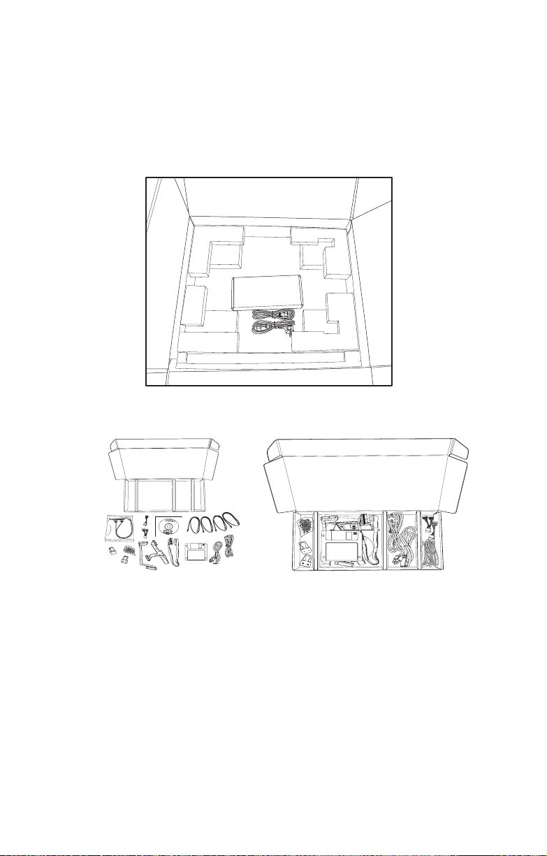
Open the box carefully and ensure that all components are
present and undamaged. The product should arrive packaged as illustrated below.
Box contents as packaged
1.3 Features
Accessory pack Accessories as packaged
Chapter 1: Overview 5
Page 12
1.4 About the product
disc
1.4 About the product
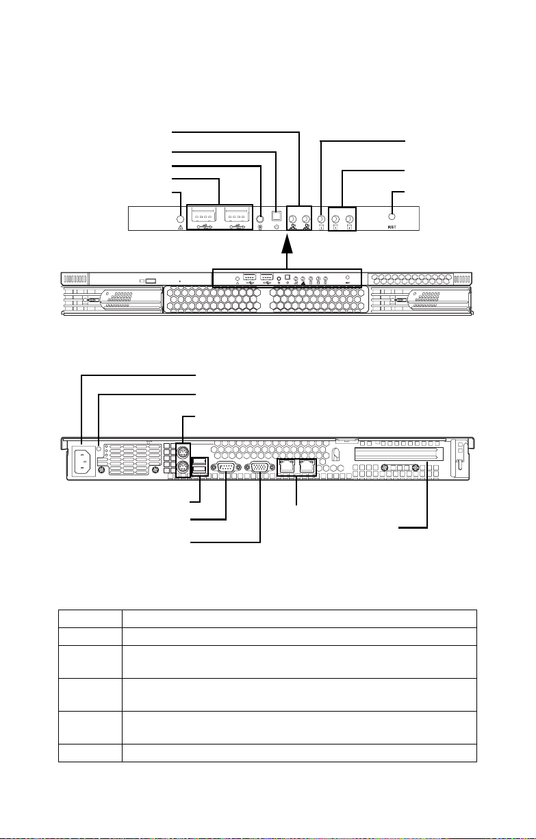
1.4.1 System front view and front panel
LAN activity
indicator
Power switch
Power indicator
USB ports
Warning
1.4.2 System rear view
EPS 12V 500W PSU
Power Supply Status
Stacked PS/2 mouse and keyboard ports
USB ports
Serial port (COM 1)
VGA port
RJ-45 LAN ports
PCI Expansion slot
HDD activity
indicator
HDD1/ HDD2
activity
Reset switch
Power supply status
A single bi-colored LED indicating power supply status as described below.
LED Power Supply Condition
Off No AC power to all power supplies
Amber Power supply critical event causing a shutdown; failure, OCP,
OVP, Fan Fail.
Blinking
Amber
Blinking
Power supply warning events where the power supply continues
to operate: high temp, high power, high current, slow fan.
AC present/Only 5VSB on (PS off)
Green
Green Output ON and OK
6 Chapter 1: Overview
Page 13
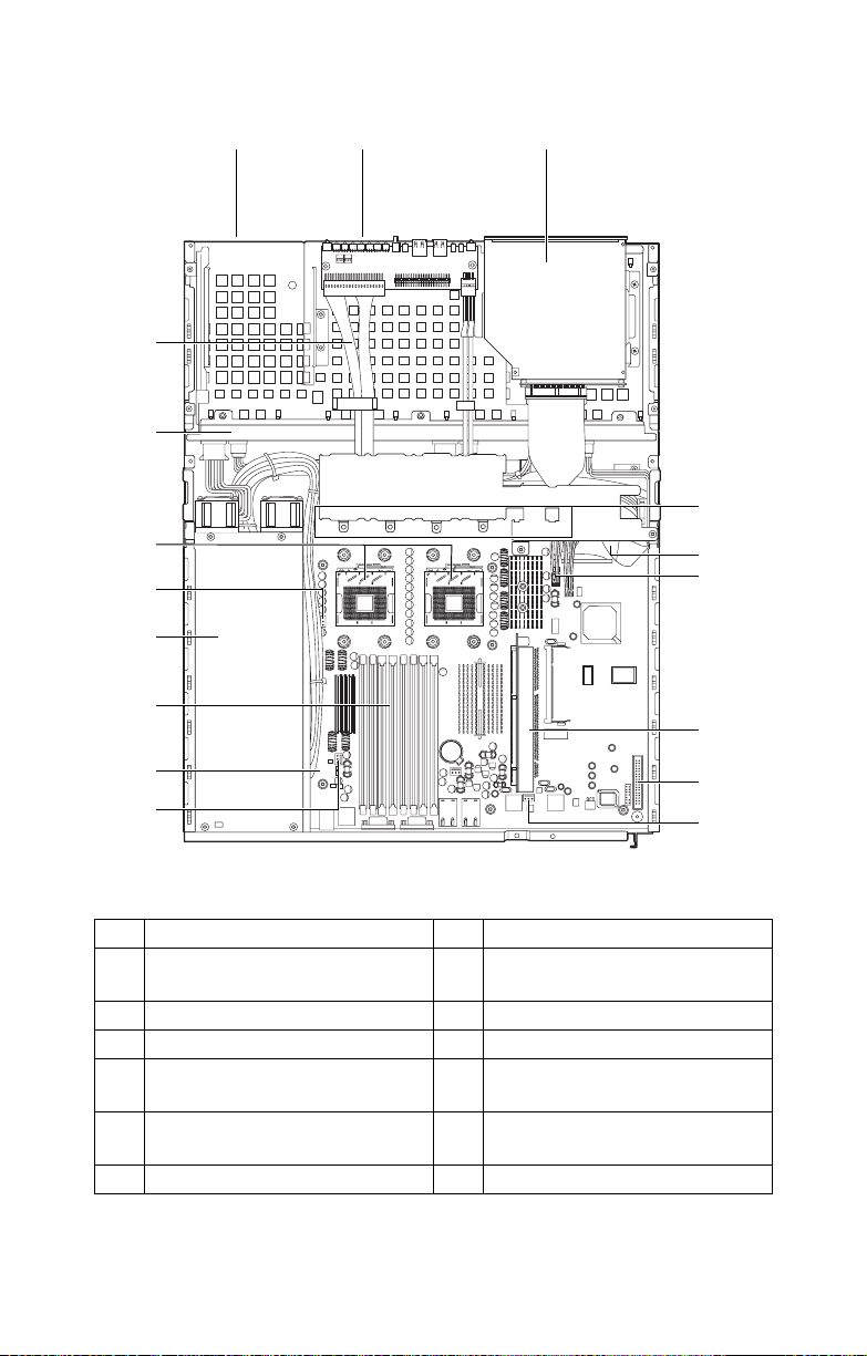
1.4.3 System internal views
12 3
14
13
1.4 About the product
4
12
6
11
10
9
6
5
6
7
8
6
1 Floppy disk drive bay 8 FDD connector
2 LED control board 9 Power connector (located
underneath the cabling)
3 Slim CD-ROM drive 10 Memory slots
4 Fan bracket 11 EPS 12V 500W power supply
5 IDE connector (located under-
12 Processor sockets
neath the fan bracket)
6 Fan connectors 13 1-port S-ATA backplane
board x 2pcs
7 Riser card 14 Front panel cables
Chapter 1: Overview 7
Page 14
1.4 About the product
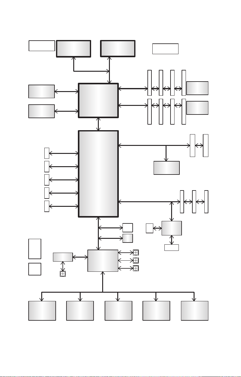
Block diagram
CPU0 VRD
BCM5721 GLAN
BCM5721 GLAN
PRIMARY
IDE CONN
SECONDARY
IDE CONN
SATA
CONNx2
USB REAR
CONNx2
USB FRONT
CONNx2
CK409B
CLOCK
SYNTH
DRVR
DB800
BUFFER
NOCONA
PCI-EX 1
PCI-EX 1
ADM1027
HOST BUS 800
LINDENHURST
Hance Rapids
FANx
NOCONA
VS
MCH
HI 1.5
LPC BUS
LPC BUS
SUPER-I/O
DME 1737
CPU1 VRD
DDR 266/333 ECC REGISTERED DIMMs A
MEM CNTRL AND DATA
MEM CNTRL AND DATA
DDR 266/333 ECC REGISTERED DIMMs B
SO-DIMM 200
PCI 32/33MHz
8MB DISPLAY
MEMORY
SERVER
MGMT
CONN
BIOS
FIRMWARE
8Mb
HUB
CPU_FAN1
CPU_FAN2
CHASSIS_FAN
ATI
RAGE XL
2.5V VRD
DDR PWR
1.25V VRD
DDR TERM
PCI-X SLOT
PCI 32/33MHz SLOTs
CRT CONN
PRINTER
HEADER
SERIAL
HEADER
SERIAL
PORT
KBD
PORT
FLOPPY
CONN
8 Chapter 1: Overview
Page 15

2.1 Before you begin
This chapter explains how to install motherboard components
including CPUs, memory modules, and PCI cards. There are
also instructions in this section for installing S-ATA and IDE
hard drives.
Careful attention should be given to the precautions mentioned in this section when setting up your system.
2.1.1 Work area
Make sure you have a stable, clean working environment.
Dust and dirt can get into components and cause malfunctions. Use containers to keep small components separated.
Putting all small components in separate containers prevents
them from becoming lost. Adequate lighting and proper tools
can prevent you from accidentally damaging the internal
components.
2.1 Before you begin
Chapter 2: Setting up
2.1.2 Tools
The following tools will be required to complete the installations described in this chapter.
• A cross head (Phillips) screwdriver
• A grounding strap and/or anti static pad
Most of the electrical and mechanical connectors in your system can be disconnected using your fingers. It is recommended that you do not use needle-nosed pliers to remove
connectors as these can damage the soft metal or plastic
parts of the connectors.
Chapter 2: Setting up 9
Page 16

2.1 Before you begin
2.1.3 Precautions
Components and electronic circuit boards can be damaged
by static electricity. Working on a system that is connected to
a power supply can be extremely dangerous. Follow the
guidelines below to avoid damage to the Transport GX21 or
injury to yourself.
• Ground yourself properly before removing the top
cover of the system. Unplug the power from the
power supply and then touch a safely grounded
object to release static charge (i.e. power supply
case). If available, wear a grounded wrist strap. Alternatively, discharge any static electricity by touching
the bare metal chassis of the unit case, or the bare
metal body of any other grounded appliance.
• Avoid touching motherboard components, IC chips,
connectors, memory modules, and leads.
• The motherboard is pre-installed in the system.
When removing the motherboard, always place it on
a grounded anti-static surface until you are ready to
reinstall it.
• Hold electronic circuit boards by the edges only. Do
not touch the components on the board unless it is
necessary to do so. Do not flex or stress circuit
boards.
• Leave all components inside the static-proof packag-
ing that they ship with until they are ready for installation.
• After replacing optional devices, make sure all
screws, springs, or other small parts are in place and
are not left loose inside the case. Metallic parts or
metal flakes can cause electrical shorts.
• Always use the correct size screws and fixings when
installing or replacing components.
Note: All connectors are designed to fit
one way only, no force should required to
make a connection.
10 Chapter 2: Setting up
Page 17
2.2 Installing motherboard components
2.2 Installing motherboard components
This section describes how to install CPUs, memory modules
and PCI card.
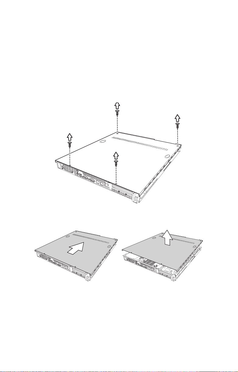
2.2.1 Removing the chassis cover
Follow these instructions to remove the Transport GX21
(B5350) chassis cover. This step is required before any other
procedures in this chapter can be undertaken.
1. Remove the four screws that secure the chassis cover.
2. Slide the cover in the direction of the arrow (A) and then
lift the cover off (B).
A
Chapter 2: Setting up 11
B
Page 18
2.2 Installing motherboard components
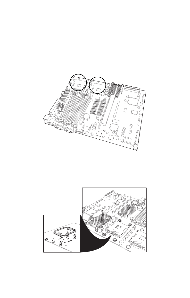
2.2.2 Installing CPUs
This section describes how to install Intel® Xeon processors
and heatsinks in your Transport GX21 (B5350) system. This
section applies to all models.
1. Remove the chassis cover as described in section 2.2.1
Removing the chassis cover.
2. Locate the CPU sockets on the motherboard as shown
below.
3. Turn the motherboard upside down to install the heat sink
springs, in the order shown. See 3.2.2 Replacing the
motherboard for instructions on how to remove the motherboard.
A
12 Chapter 2: Setting up
Page 19
2.2 Installing motherboard components
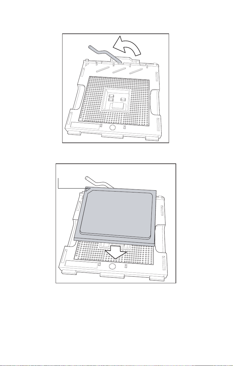
4. Lift the CPU locking lever as shown below.
5. Place the CPU in the CPU socket, ensuring that pin 1 is
located as shown in the following illustration.
pin 1
6. Press the CPU locking lever back down to secure the
CPU in the socket.
7. Repeat steps three to six for the second CPU.
8. Apply thermal grease to the top of the CPUs and place
the CPU heatsinks on the CPUs.
Chapter 2: Setting up 13
Page 20
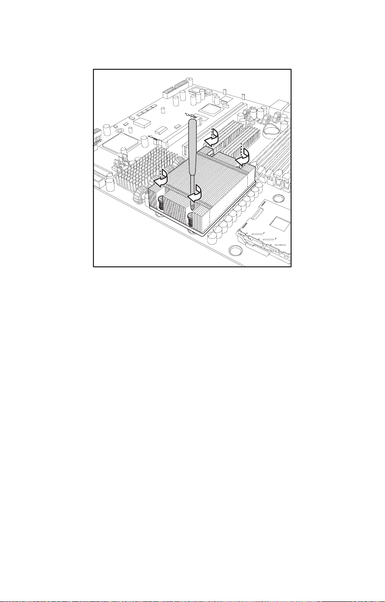
2.2 Installing motherboard components
9. Tighten the four screws to secure the heatsinks in place
as shown below.
Note: CPU heatsinks must be removed to
install or remove memory modules.
14 Chapter 2: Setting up
Page 21
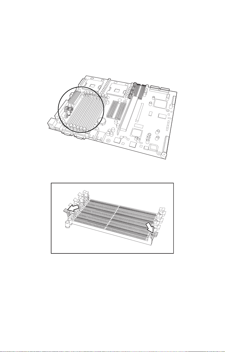
2.2.3 Installing memory
Follow the instructions in this section to install memory modules in your Transport GX21 (B5350) system.
1. Remove the chassis cover as described in section 2.2.1
Removing the chassis cover.
2. Locate the memory slots on the motherboard.
3. Press the memory slot locking levers in the direction of
the arrows as shown below.
2.2 Installing motherboard components
Note: It is not possible to move the mem-
ory slot locking levers without first removing
the CPU heatsinks.
4. Align the memory module with the slot. The module will fit
only one way in the slot. Ensure that indentations in the
memory module line up with corresponding notches in
the memory slot.
Chapter 2: Setting up 15
Page 22

2.2 Installing motherboard components
5. Insert the memory module into the slot as shown.
6. Ensure that the locking levers are firmly in place and that
the memory module is properly seated in the slot.
2.2.4 Installing a PCI card
Follow the instructions in this section to install a PCI card in
your Transport GX21 (B5350) system.
1. Remove the chassis cover as described in section 2.2.1
Removing the chassis cover.
2. Remove the PCI retention bar.
16 Chapter 2: Setting up
Page 23

2.2 Installing motherboard components
3. Remove the screw securing the PCI faceplate to the
chassis.
4. Slide the PCI card clamp out as shown.
5. Slide the dust cover out.
Chapter 2: Setting up 17
Page 24

2.2 Installing motherboard components
6. Press the PCI card into place in the slot on the riser card.
Ensure that the card is seated properly in the slot on the
riser card and that the riser card is properly seated in its
slot on the motherboard.
Insert PCI card tip
in slot here
Riser card
7. Reinsert the PCI card clamp.
18 Chapter 2: Setting up
Page 25

2.2 Installing motherboard components
8. Insert the screw to secure the PCI card to the chassis.
Chapter 2: Setting up 19
Page 26

2.3 Installing a hard drive
2.3 Installing a hard drive
Follow these instructions to install hard drives in your system.
2.3.1 Installing an external S-ATA hard drive
Follow these instructions to install an external S-ATA hard
drive in your system.
1. Remove the chassis cover as described in section 2.2.1
Removing the chassis cover.
2. Press the drive bay locking latch in the direction of the
arrow (A) and pull the locking lever open (B).
A
B
3. Slide the drive bay out.
20 Chapter 2: Setting up
Page 27

2.3 Installing a hard drive
4. Place a S-ATA drive in the drive bay.
Note: If you are replacing an existing HDD,
you will need to remove the four screws that
secure it in the drive bay and remove it.
5. Insert four screws to secure the new unit in the drive bay.
Chapter 2: Setting up 21
Page 28

2.3 Installing a hard drive
6. Reinsert the drive bay into the chassis. Ensure that the
rear connector of the new drive is firmly seated in the
backplane.
22 Chapter 2: Setting up
Page 29

2.4 Rack mounting
Follow these instructions to mount the Transport GX21
(B5350) into an industry standard 19" rack.
Note: Before mounting the Transport GX21 in a
rack, ensure that all internal components have been
installed and that the unit has been fully tested.
Maintenance can be performed on the unit while in
a rack but it is preferable to install the device in a
fully operational condition.
1. Screw the mounting ears to the Transport GX21 as
shown using 4 screws from the supplied nuts, screws
and washers kit.
2.4 Rack mounting
2. Screw the sliding rail mounting brackets to the sliding
rails as shown, using the short black screws from the
supplied nuts, screws and washers kit.
Note: Ensure that the brackets with the cut away
section (to accommodate the handles on the front
of the unit) are fixed to the front end of the rail.
3. Fully extend the sliding rails until they lock.
Chapter 2: Setting up 23
Page 30

2.4 Rack mounting
Note: Do not tighten the brackets to the rails as
you will need to adjust their position later.
4. Screw each sliding rail to the side of the Transport GX21
as shown. You will need 3 short, silver colored screws
from the supplied nuts, screws and washers kit, for each
rail.
5. Return the sliding rails to their shortest position.
Note: When fully extended, the sliding rails
will lock. The release mechanism is located
on the sliding rail as shown. Press the
release mechanism while pushing the sliding
rails to shorten them.
24 Chapter 2: Setting up
Page 31

2.4 Rack mounting
6. With the rails in their shortest position, adjust both front
mounting brackets so that they are flush with the front of
the unit.
7. Accurately measure the depth of your rack and adjust the
rear brackets accordingly.
8. When all brackets are positioned correctly, tighten them.
9. Lift the unit into place in the rack and screw it into place
as shown.
disc
Note: To avoid injury, it is strongly recom-
mended that two people lift the
Transport GX21 into place while a third person screw it to the rack.
Chapter 2: Setting up 25
Page 32

2.4 Rack mounting
26 Chapter 2: Setting up
Page 33

3.1 Introduction
Chapter 3: Replacing installed components
3.1 Introduction
This chapter describes how to replace all the pre-installed
components of your Transport GX21 (B5350), including
motherboard, CD-ROM drive, floppy disk drive and LED control board. There is also a section covering the replacement
for two 1-port S-ATA backplanes.
Before you attempt to replace any components, make sure
you have read section 2.1 Before you begin, in chapter 2,
which describes the precautions you need to take and the
tools you will require.
3.2 Replacing motherboard components
Follow these instructions to remove motherboard components and replace the motherboard.
3.2.1 Disconnecting all motherboard cables
When replacing the motherboard or certain motherboard
components, it my be necessary to remove cables connected
to the motherboard.
Chapter 3: Replacing installed components 27
Page 34

3.2 Replacing motherboard components
1. Disconnect power cables.
Note: There are two air ducts, leading from
the fans, covering the CPUs.
2. Disconnect CD-ROM drive cable and
S-ATA hard drive cable.
28 Chapter 3: Replacing installed components
Page 35

3.2 Replacing motherboard components
Note: If there is an FDD installed you will
have to disconnect those cables too before
you can remove the motherboard.
3. Disconnect front panel LED and USB connectors.
Front panel LED connector
USB connector
4. Remove fan and COM port connectors
Chapter 3: Replacing installed components 29
Page 36

3.2 Replacing motherboard components
3.2.2 Replacing the motherboard
Follow these instructions to remove the motherboard from
your Transport GX21 (B5350).
Note: Before removing the motherboard
you must remove all cable connections to the
motherboard. See section 3.2.1 Disconnect-
ing all motherboard cables for details on how
to do this.
1. Remove the two airducts covering the CPUs
and the fan assembly bracket from the chassis.
2. Remove the PCI retention bar.
30 Chapter 3: Replacing installed components
Page 37

3.3 Replacing the CD-ROM drive
3. Remove the nine screws that secure the motherboard to
the chassis.
4. Remove the motherboard from the chassis.
3.3 Replacing the CD-ROM drive
This section describes how to remove and replace the CDROM drive in your Transport GX21 (B5350) system.
1. Remove the chassis cover as described in section 2.2.1
Removing the chassis cover.
2. Disconnect the CD-ROM power and data cables.
3. Remove the two screws that secure the CD-ROM to the
chassis.
Chapter 3: Replacing installed components 31
Page 38

3.4 Replacing the LED control board
4. Remove the two screws that secure the CD-ROM backplane to the CD-ROM drive.
5. Lift the drive from the chassis.
3.4 Replacing the LED control board
Follow these instructions to replace the LED control board.
32 Chapter 3: Replacing installed components
Page 39

3.5 Replacing the storage backplane
1. Remove the front panel ribbon cable from the rear of the
LED control panel.
2. Remove the two screws that secure the LED control
panel to the chassis and lift the board free of the chassis.
3.5 Replacing the storage backplane
This section describes how to replace the S-ATA backplane
on your Transport GX21 (B5350).
1. Remove the chassis cover as described in section 2.2.1
Removing the chassis cover.
2. Remove all cables connected to the S-ATA backplane,
including power cables, and S-ATA data cables.
Chapter 3: Replacing installed components 33
Page 40

3.5 Replacing the storage backplane
Note: You must remove the CD-ROM,
front panel and FDD cables before removing
the backplane. See 3.2 Replacing mother-
board components for details on how to do
this.
3. Remove the three screws that secure the S-ATA backplane bracket to the chassis.
4. Remove the S-ATA backplane bracket and backplanes
free from the chassis.
5. Remove the six screws that secure the S-ATA backplane
to the bracket.
6. Remove the S-ATA backplane.
34 Chapter 3: Replacing installed components
Page 41

3.5 Replacing the storage backplane
3.5.0.1 S-ATA backplane features
J1 DC power input
connector
J3 serial ATA 7
pin connector
FAN1 Fan
connector
JP2 HDD LED
connector
Note: B5350G21S2H is shipped with two
1-port S-ATA backplanes to support 2 hotswap S-ATA hard disk drives
Chapter 3: Replacing installed components 35
Page 42

3.6 Replacing the power supply
3.6 Replacing the power supply
Follow these instructions to replace the power supply in your
Transport GX21 (B5350) system.
1. Remove the chassis cover as described in section 2.2.1
Removing the chassis cover.
2. Disconnect power cables from the motherboard, backplanes, FDD, CD-ROM drive and fans. See 2.3 Installing
a hard drive, 3.2.1 Disconnecting all motherboard
cables, section 3.3 Replacing the CD-ROM drive, 3.5
Replacing the storage backplane, and section 3.4
Replacing the LED control board for details on how to do
this.
3. Remove the two screws that secure the power supply to
the chassis and lift the unit free.
36 Chapter 3: Replacing installed components
Page 43

3.7 Replacing the cooling fans
3.7 Replacing the cooling fans
Follow these instructions to replace the cooling fans in your
Transport GX21 (B5350) system.
1. Remove the chassis cover as described in section 2.2.1
Removing the chassis cover.
2. Remove the PCI retention bar
Note: You may need to cut the cable ties
that secure the fan power cables before
attempting to unplug them.
3. Remove the power cables for the 5 fans from the motherboard.
4. Remove the two screws that secure the fan bracket to the
chassis.
5. Lift the fan bracket free of the unit
Chapter 3: Replacing installed components 37
Page 44

3.7 Replacing the cooling fans
6. Remove the four screws securing each fan to the fan
bracket to remove them from the fan bracket.
Note: The Transport GX21 (B5350) uses
two different types of cooling fans which
operate at different speeds. The fan installed
nearest the power supply has a peak speed
of 15,000 rpm. The other 4 fans have a peak
speed of 15,500 rpm. The fan nearest the
power supply should be connected to the
speed-controllable pin header (CPU1_FAN)
on the mother board.
38 Chapter 3: Replacing installed components
Page 45

BIOS
Appendix
Introduction
Your Transport GX21 (B5350) system includes a powerful
Tiger i7320R S5350 motherboard with Phoenix BIOS on 8
MBit flash ROM.
The BIOS is the motherboard’s basic input/output system.
The BIOS contains all the settings required to control the keyboard, display, disk drives, serial communications, and a
number of miscellaneous functions. This section of the
appendix describes the various BIOS settings that can be
used to configure your system.
BIOS setup utility
With the BIOS setup utility, you can modify BIOS settings and
control the features of your system. The setup utility uses a
number of menus.
Note: All menus shown in this section are
based on a typical system. The actual menus
displayed on your screen may look different
depending on the hardware and features
installed.
To start the BIOS setup utility:
1. Turn on or reboot your system.
2. Press <Del> during POST (F4 on remote console) to
start the BIOS setup utility.
Appendix 39
Page 46

BIOS setup utility
To select an item:
Use the <Arrow> keys to make a selection.
To display a submenu (a pointer marks all submenus)
Use the arrow keys to move the cursor to the required submenu and press <Enter>.
BIOS menu bar
The menu bar at the top of the window lists the following
selections:
Menu bar selections
Main Configure basic system setup options
Advanced Configure advanced chipset options
Security Configure user and supervisor passwords
Power Configure power management
Boot Configure system boot order
Exit Exit setup utility
40 Appendix
Page 47

Note: Options written in bold type repre-
sent the BIOS setup default.
BIOS legend bar
The following chart describes the legend keys and their functions.
Key Function
<F1> General help window
<ESC> Exit current window
ÅÆ arrow keys Move between menus
ÇÈ arrow keys Move cursor up/down
<Tab> or <Shift-Tab> Select submenu
<Home> or <End> Move cursor to the top or bottom of the window
<PgUp> or <PgDn> Move cursor to the next or previous page
<Plus> or <Minus> Change value
<F9> Load setup default configuration values
<F10> Save and exit
<Enter> Select submenu
BIOS main menu
The Main BIOS menu is the first screen that appears when
you enter BIOS setup. The menu has two main frames. The
left frame displays all the options that can be configured.
"Grayed-out" options cannot be configured, options in blue
can be changed.
The right frame displays the key legend. Above the key legend is an area reserved for a text message. When an option
is selected in the left frame, it is highlighted in white. Often, a
text message will accompany it.
Appendix 41
Page 48

Feature Option Description
System Time HH:MM:SS Set the system time
System Date MM:DD:YY Set the system date
Legacy Diskette A:NONE /
360 K, 5.25 in /
1.2 M, 5.25in /
720K, 3.5 in /
1.44 M, 3.5 in /
2.88, 3.5 in
IDE Channel submenu Set IDE drive configuration
Memory Cache submenu Set memory caching
Boot Features submenu Set boot options
System Memory Set system memory
Extended Memory
Set the floppy drive type
Set extended memory
42 Appendix
Page 49

IDE channel submenus
You can use this screen to change IDE Configuration Settings.
Appendix 43
Page 50

Feature Option Description
Cylinders Set number of cylinders on disk
Heads Set number of heads on disk
Sectors Set number of sectors on disk
Maximum Capacity
Multi-Sector
Transfers
LBA Mode
Control
32-bit I/O Enabled / Disabled Set 32-bit I/O on or off
Transfer Mode Auto / Standard
Ultra DMA Mode Disabled / Mode 0 /
Disabled / 2 sectors
4 sectors / 8 sectors
16 sectors
Enabled / Disabled Set LBA on or off
Fast PIO 1 / Fast PIO
2 / Fast PIO 3 / Fast
PIO 4 / FPIO 3 / DMA
1 / FPIO 4 / DMA 2
Mode 1 / Mode 2
Set maximum size of disk
Set number of sectors per block
for multiple sector transfers
Set transfer mode for data to
disk
Set Ultra DMA mode
Note: Selecting Auto will automatically
detect IDE settings.
44 Appendix
Page 51

Memory cache
You can use this screen to change memory caching settings
Feature Option Description
Cache System
BIOS area
Cache Video BIOS
area
NULL / Write
Protect
NULL / Write
Protect
Cache system BIOS ROM
(shadowing must be enabled)
Cache video BIOS ROM (Shadowing must be enabled)
Appendix 45
Page 52

Boot features
You can use this screen to set boot parameters.
Feature Option Setting
Floppy Check Enabled / Disabled Set check for floppy disk at
POST on or off
Summary Screen Enabled / Disabled Set a summary of BIOS settings
at POST on or off
Quiet Boot Enabled / Disabled Set the OEM logo during boot up
on or off
QuickBoot Mode Enabled / Disabled Speed up booting by shortening
test procedure
Extended Memory
Testing
Normal / Just zero it
/ None
Set test for extended memory at
POST
46 Appendix
Page 53

BIOS advanced menu
You can use this menu to configure advanced BIOS settings.
Features Option Description
Hardware Monitor submenu Set hardware monitor options
Enable ACPI Yes / No
Installed OS Other / Win95
/ Win98 /
WinMe /
Win2000
Reset Configuration
Data
Large Disk Access
Mode
Parallel ATA Preliminary /
Serial ATA Enabled /
Yes / No Force BIOS to discard old config-
DOS / Other Set access mode for disks over
Secondary /
Both
Disabled
Set the installed operating system
Note: Incorrect settings may
cause the system to behave
unpredictably.
uration and re-detect hardware
C1024 H16 S64
Set controller for parallel ATA
devices
Set booting from S-ATA devices
on or off
Appendix 47
Page 54

Features Option Description
Native Mode Operation Auto / Paral-
lel ATA /
Serial ATA /
Both
SATA RAID Enable Enabled /
Disabled
Advanced Chipset Control
Advanced Processor
Options
I/O Device
Configuration
DMI Event Logging submenu Set DMI event logging
Legacy USB Support Enabled /
submenu Configures USB controller and
submenu Set advanced processor options
submenu Configure I/O devices
Disabled
Set S-ATA devices to operate in
native or emulated mode
Set RAID BIOS loading on start
up
legacy device support
Set control of USB ports for operating systems that do not support
USB
48 Appendix
Page 55

Hardware monitor
You can use this screen to change critical system settings.
Appendix 49
Page 56

Advanced chipset control submenu
Use this screen to fine tine the chipset.
Feature Option Description
Integrated Device
Control Sub-Menu
Integrated LAN 1 submenu
Integrated LAN 2 submenu
Spectrum Spread
Force Compliance
Mode Entry
DRAM Data Integrity Mode
ECC Error Type None / NMI /
SERR Signal Condition
submenu
Enabled
Disabled
Disabled
72-bit ECC
144-bit ECC
Auto
SMI / SCI
None
Single bit
Multiple bit
Both
Set PCI-E compliance mode
Set ECC mode for ECC memory modules
Set the type of interrupt generated
when an ECC error occurs
Set the error conditions on which
SERR is sent
50 Appendix
Page 57

Feature Option Description
Memory Remap
Function
Enabled
Disabled
Integrated Device Control Submenu
Use this screen to control USB.
Remap BIOS memory to above 1 MB
(BIOS cannot be shadowed when this
is enabled)
Feature Option Description
USB Device 29
Function
Enabled/Disabled Set functions of USB on or off
Appendix 51
Page 58

Integrated LAN 1 and 2 submenus
You can use these screens to set options for the integrated
LANs.
Feature Option Description
PCI-E port Auto / Disabled /
Enabled / Force PCI
Express v1.0 Compatibility Mode
Option ROM Scan Enabled / Disabled Initialize device expansion
Set PCI-E compatibility mode
ROM
52 Appendix
Page 59

Advanced Processor Control submenu
Feature Option Description
Hyper Threading
Technology
Thermal Management 2
Set Max Ext
CPUID=3
Enabled
Disabled
Enabled
Disabled
Enabled
Disabled
Enable Hyper-Threading (only if
supported by processor)
Prevent damage to the CPUs by
slowing the processor. Full
speed resumes when a stable
temperature is reached
Set the Max CPUID extended
function value to 3
Appendix 53
Page 60

I/O Device Configuration submenu
You can use this screen to configure I/O Devices.
Feature Option Description
Serial port A Enabled / Disabled Turn serial port A on or off
Base I/O address 3F8 / 2F8 / 3E8 / 2E8 Set the base I/O address for
serial port A
Interrupt IRQ3 / IRQ4 Set the interrupt for serial port A
Serial port B Enabled / Disabled Turn serial port B on or off
Base I/O address 3F8 / 2F8 / 3E8 / 2E8 Set the base I/O address for
serial port B
Interrupt IRQ3 / IRQ4 Set the interrupt for serial port B
Mode Normal / IrDA / ASK-IRSet the mode for the type of
device to be attached to serial
port B
Parallel Port Enabled / Disabled Turn the parallel port on or off
Mode SPP / EPP / EC Set the mode for the type of
device to be attached to the parallel port
Base I/O and Interrupt
Disabled
378/IRQ7
278/IRQ5 3BC/IRQ7
Set the base I/O address and
interrupt for the parallel port
54 Appendix
Page 61

Feature Option Description
DMA Channel DMA 1 / DMA 3 Set the DMA channel for the par-
allel port
Floppy disk controller
Enabled / Disabled Set the Floppy Disk on or off
Appendix 55
Page 62

DMI Event Logging submenu
Use this screen to set DMI event-logging options.
Feature Option Description
Event Logging Enabled / Disabled Set DMA Logging on or off
ECC Event
Logging
Clear all DMI event
logs
Enabled / Disabled Set ECC Logging on or off
Yes / No Clear all DMI logs after rebooting
56 Appendix
Page 63

Console Redirection submenu
Use this screen to set options for external control using a
console.
Feature Option Description
Com Port Address Disabled / On-board
COM A / On-board
COM B / NULL
Baud Rate 300 / 1200 / 2400 /
9600 / 19.2K / 38.4K
/ 57.6K / 115.2K
Console Type VT100 / VT100,8bit /
PC-ANSI, 7bit / PC
ANSI / VT100+ / VTUTF8 / NULL
Flow Control NULL / XON/XOFF /
CTS/RTS
Console
Connection
Continue C.R. after
POST
Direct / Via modem Set modem or direct connection
On / Off Enable console redirection after
Enable onboard COM ports for
external console use
Set the baud rate for the COM
port
Set the console type
Enable flow control
the operating system has loaded
Appendix 57
Page 64

ASF Configuration submenu
You can use this screen to set ASF options.
Feature Option Description
Minimum
Watchdog Timeout
BIOS Boot
Timeout
OS Boot Timeout Time for OS to boot before
Power-on wait
time
Set the time for BIOS to stop the
Watchdog Timer after a reset
has occurs
Set time for BIOS to boot before
the system is reset
system is reset
Set maximum amount of time for
Alert Sending Device to connect
with its transport media
58 Appendix
Page 65

Security menu
You can use this screen to set security options for your computer.
Feature Option Description
Set Supervisor
Password
Set User
Password
Password on boot Set system to ask for password
Set the supervisor password
which restricts access to the
BIOS
Set user password
at start up. Failure to enter the
correct password within three
attempts will result in system
shutdown
Appendix 59
Page 66

Power menu
You can use this screen to configure power management.
Feature Option Description
Resume On Time On / Off Set a time for the system to
automatically power on
Power Button
Behavior
After power Failure Enabled
Chassis Intrusion
Detect
Power On By
PCI/PCI-X
On/Off
Wake/Sleep
Disabled
Enabled
Disabled
Enabled
Disabled
Set power button to switch
power on and off or sleep and
wake up
Set the system to return to
previous state or stay powered
off after a power failure
Set BIOS to record chassis intrusion events
Set system to wake up from
sleep mode on PCI card input
60 Appendix
Page 67

Boot menu
You can use this screen to set boot up options.
Appendix 61
Page 68

Exit menu
You can use this screen to save or discard changes and load
factory defaults.
Feature Option Description
Exit Saving Changes Save changes made and
exit BIOS
Exit Discarding
Changes
Load Setup Defaults Restore all BIOS settings to
Discard Changes Restores settings to
Save Changes Saves settings at their cur-
Discard changes made and
exit BIOS
factory defaults
previous values
rent values
62 Appendix
Page 69

Technical support
If a problem arises with this system, you should consult your
dealer first for help. The system is likely to have been configured by your dealer, making him the most appropriate choice
when seeking technical advice. Your dealer may also be
close enough to visit with the hardware for servicing or testing.
Help resources:
1. See the TYAN website for FAQs, bulletins, driver updates
and other information: http://www.tyan.com
2. Only contact TYAN after first speaking with your dealer
3. Check the TYAN user group:
alt.comp.periphs.mainboard.TYAN
Returning merchandise for service
If any problems occur during the product’s warranty period,
consult your system vendor or distributor before contacting
TYAN. The warranty covers normal customer use of the
product. The warranty does not cover damages sustained
during shipping or failure due to alteration, misuse, abuse, or
improper maintenance of the unit.
Note: A receipt or copy of your invoice,
marked with the date of purchase, is required
before any warranty service can be provided.
You may obtain service by calling the manufacturer for a Return Merchandise Authorization (RMA) number. The RMA number
should be displayed prominently on the outside of the shipping carton, and the package
should be mailed prepaid. TYAN will pay to
have the product shipped back to you.
Transport GX21 (B5350) User’s Manual.
Appendix 63
Page 70

64 Appendix
 Loading...