

Page 1

DP RS422/485 PCI
Express Adapter Card
Quick Installation Guide
Introduction
The DP RS422/485 PCI Express Adapter Card is a
high-speed serial card that provides additional
serial ports to your system.
Key Features and Benefits
• Compliant with PCI Express Base
Specification, Revision 1.1
• Supports serial port transfer rate up to
921Kb/s
• Built-in 15KVDC ESD serial interface
protection
• Built in 128-byte FIFO buffer
• RS-422 & RS485 auto detect and switch
• Plug-n-Play, I/O address and IRQ assigned
by BIOS
04-0810A
1
Page 2

System Requirements
• PCI Express equipped system with an
available PCI Express slot
• Windows
®
7 (32-/64-bit) / Vista (32-/64bit) / XP (32-/64-bit) / Server 2003 &
2008(32-/64-bit) / Server 2008 R2 / 2000
Package Contents
• DP RS422/485 PCI Express Adapter Card
• Spare enhanced low-profile bracket
• Fan Out Cable
• Jumper (4pcs for ID-P20211-S1; 8pcs for
ID-P40411-S1 )
• Quick installation guide
• Driver CD
2
Page 3
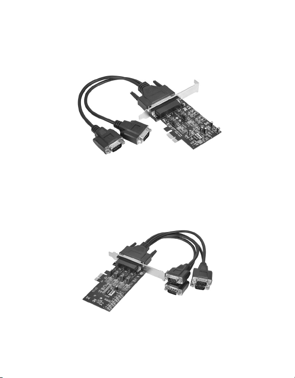
Layout
ID-P20211-S1
Figure 1: 2-Port RS422/485 PCI Express Adapter Card
ID-P40411-S1
Figure 2: 4-Port RS422/485 PCI Express Adapter Card
3
Page 4
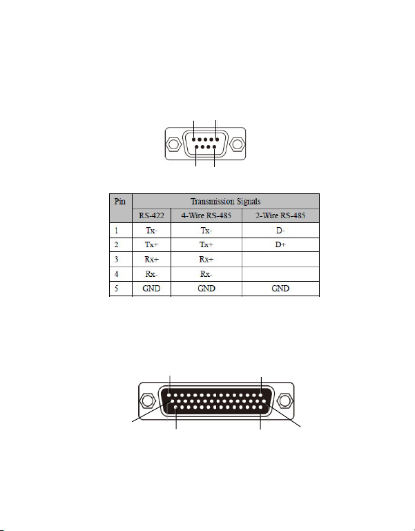
Pin Assignment
Male DB9 Connector:
1
69
Female DB44 Connector:
5
15
30
4
44
1
31
16
Page 5
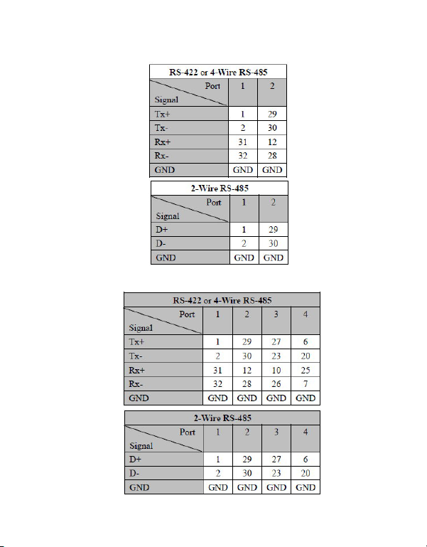
2-Port RS422/485 PCI Express:
4-Port RS422/485 PCI Express:
5
Page 6
Jumper Settings
RS-422 or 4-wire RS-485 working model with
termination resistor
2-wire RS-485 working model with termination
resistor
This RS-422/485 PCI Express Serial board equips
independent TX and RX termination resistors for
each serial port. User can modify the jumper
setting (short the pins) to avoid impedance
mismatched problem when operate under Multidrop transmission. Resistors should be added
near the receiving side.
6
Page 7

Default jumper setting is Open (disconnect 120
ohms termination resistors across the two wires)
DP 2-Port RS422/485 PCI Express Adapter Card
J4
J1
Figure 3: ID-P20211-S1 Pin Layout
7
Page 8

Figure 4: ID-P20211-S1 Pin Assignment
1. Pin 1-2 jumper setting is short by default,
Auto Detect / RS-485(2-Wire)
This COM port can automatically detect
the state of RS-422 full duplex or RS-485
half duplex and control the data
transmitting and receiving wires at the same
port.
2. Pin 2-3 jumper setting is short for RS-422/
RS-485(4-Wire)
This COM port forces to run RS-422 full
duplex mode.
8
Page 9

DP 4-Port RS422/485 PCI Express Adapter Card
J1
J7
J8
J2
Figure 5: ID-P40411-S1 Pin Layout
Figure 6: ID-P40411-S1 Pin Assignment
9
Page 10

1. Pin 1-2 jumper setting is short by default,
Auto Detect / RS-485(2-Wire)
This COM port can automatically detect
the state of RS-422 full duplex or RS-485
half duplex and control the data
transmitting and receiving wires at the same
port.
2. Pin 2-3 jumper setting is short for RS-422/
RS-485(4-Wire)
This COM port forces to run RS-422 full
duplex mode.
10
Page 11

Hardware Installation
General instructions for installing the card are
provided below. Since the design of computer
cases and motherboards vary, refer to your
computer’ s reference manual for further
information, if needed.
Static Electricity Discharge may permanently
damage your system. Discharge any static
electricity build up in your body by touching your
computer’ s case for a few seconds. Avoid any
contact with internal parts and handle cards
only by their external edges.
Note: For low profile chassis, remove the
standard height bracket and install the
enhanced low-profile bracket now.
1. Turn OFF the power to your computer and
any other connected peripheral devices.
2. Unplug the power cord and remove the
cover from the computer.
3. Remove the slot bracket from an available
PCIe slot.
11
Page 12

4. To install the card, carefully align the card's
bus connector with the selected PCIe slot on
the motherboard. Push the board down
firmly, but gently, until it is well seated.
5. Replace the slot bracket's holding screw to
secure the card.
6. Replace the computer cover and reconnect
the power cord.
12
Page 13

Driver Installation
This section provide the steps to install the driver
of DP RS422/485 PCI Express Adapter Card.
Windows 7 (32-/64-bit) / Server 2008 R2
1. Install the board and boot up Windows.
Note: Windows 7 will automatically search
preconfigured driver folders for the proper
driver, it may take several minutes to
complete. Do not interrupt this process.
2. Insert the driver CD. Close AutoPlay if
prompted.
3. Click Start. In the Search programs and
files box, type D:\setup.exe, press Enter.
(Change D: to match your CD/DVD-ROM
drive letter)
4. Click Yes at the User Account Control
window if prompted. For 2008R2, skip this
step.
5. At the Welcome to the PLX OXPCIe952/
954 PCIe RS-422/485 Serial Cards Setup
Wizard, click Install.
13
Page 14

6. At the Completing the PLX OXPCIe952/
954 PCIe RS-422/485 Serial Cards Setup
Wizard, select Reboot now, then click Finish
to complete the installation.
Windows Vista (32-/64-bit) / Server 2008
(32-/64-bit)
1. Install the board and boot up Windows.
2. At the Found New Hardware window,
click Cancel.
3. Insert the driver CD. Close AutoPlay if
prompted.
4. Click Start. In the Start Search box, type
D:\setup.exe, press Enter. (Change D: to
match your CD/DVD-ROM drive letter)
5. Click Allow at the User Account Control
window if prompted. For 2008, skip this
step.
6. At the Welcome to the PLX OXPCIe952/
954 PCIe RS-422/485 Serial Cards Setup
Wizard, click Install.
14
Page 15

7. At the Completing the PLX OXPCIe952/
954 PCIe RS-422/485 Serial Cards Setup
Wizard, select Reboot now, then click Finish
to complete the installation.
Windows XP (32-/64-bit) / Server 2003
(32-/64-bit)
1. Install the board and boot up Windows.
2. At the Found New Hardware Wizard, click
Cancel.
3. Insert the driver CD. Close AutoPlay if
prompted.
4. Click Start, Run. Type D:\setup.exe, click
OK. (Change D: to match your CD/DVD
ROM drive letter)
5. At the Welcome to the PLX OXPCIe952/
954 PCIe RS-422/485 Serial Cards Setup
Wizard, click Install.
6. At the Completing the PLX OXPCIe952/
954 PCIe RS-422/485 Serial Cards Setup
Wizard, select Reboot now, then click Finish
to complete the installation.
15
Page 16

Windows 2000
1. At the Welcome to the Found New
Hardware Wizard, click Next.
2. Select Search for a suitable driver for my
device (recommended), and click Next.
3. Check Specify a location, uncheck the other
boxes, then click Next.
4. Insert the driver CD, type D:\x86, then
click OK. (Change D: to match your CD/
DVD-ROM drive letter)
5. Click Next and Finish.
6. Repeat steps 1-5 to complete the installation.
16
Page 17

To Verify Windows Installation
1. Check in Device Manager to verify
installation.
For Windows 7: Right click Computer, click
Manage, then click Device Manager.
For Windows Vista: Right click Computer,
click Manage, click Continue, then click
Device Manager.
For Windows XP / Server 2003 / 2000: Right
click My Computer, click Manage, click
Device Manager.
For Windows Server 2008 / Server 2008 R2:
Right click Computer, click Manage, double
click Diagnostics, then click Device
Manager.
2. Double click Ports (COM & LPT), and a
PCI Express UART Port ... should be
displayed.
17
Page 18

Changing Serial Port Number
Some serial port devices need a specific
communication port in order to function properly.
If your communication port device works, do not
make any changes.
1. Right click My Computer, click Manage,
then click Device Manager.
2. Double click Ports (COM & LPT), and
double click the PCI Express UART Port.
3. Click the Settings tab.
4. Click the down arrow next to the COM Port
Number to Use box. Select a communication
port that is not in use, then click OK.
5. Restart your system to take effect.
18
Page 19

Technical Support and Warranty
QUESTIONS? SIIG’ s Online Support has answers! Simply visit our web site at
www.siig.com and click Support. Our online support database is updated daily with
new drivers and solutions. Answers to your questions could be just a few clicks away.
You can also submit questions online and a technical support analyst will promptly
respond.
SIIG offers a lifetime manufacturer warranty with this product. This warranty covers
the original purchaser and guarantees the product to be free of any defects in materials
or workmanship for the life of the product.
SIIG will, at our discretion, repair or replace (with an identical product or product
having similar features and functionality) the product if defective in materials or
workmanship. This warranty gives you specific legal rights, and you may also have other
rights which vary from state to state. Please see our web site for more warranty details.
If you encounter any problems with this product, please follow the procedures below.
A) If it is within the store's return policy period, please return the product to the store
where you purchased from.
B) If your purchase has passed the store's return policy period, please follow the steps
below to have the product repaired or replaced.
Step 1: Submit your RMA request.
Go to www.siig.com, click Support, then REQUEST A PRODUCT REPLACEMENT
to submit a request to SIIG RMA or fax a request to 510-657-5962. Your RMA request
will be processed, if the product is determined to be defective, an RMA number will
be issued.
Step 2: After obtaining an RMA number, ship the product.
• Properly pack the product for shipping. All accessories that came with the
original package must be included.
• Clearly write your RMA number on the top of the returned package. SIIG will
refuse to accept any shipping package, and will not be responsible for a product
returned without an RMA number posted on the outside of the shipping
carton.
• You are responsible for the cost of shipping to SIIG. Ship the product to the
following address:
SIIG, Inc.
6078 Stewart Avenue
Fremont, CA 94538-3152, USA
RMA #:
• SIIG will ship the repaired or replaced product via Ground in the U.S. and
International Economy outside of the U.S. at no cost to the customer.
19
Page 20

About SIIG, Inc.
Founded in 1985, SIIG, Inc. is a leading manufacturer of IT connectivity
solutions (including Serial ATA and Ultra ATA Controllers, FireWire, USB,
and legacy I/O adapters) that bridge the connection between Desktop/
Notebook systems and external peripherals. SIIG continues to grow by adding
A/V and Digital Signage connectivity solutions to our extensive portfolio.
SIIG products offer comprehensive user manuals, many user-friendly features,
and are backed by an extensive manufacturer warranty. High quality control
standards are evident by the overall ease of installation and compatibility of
our products, as well as one of the lowest defective return rates in the industry.
SIIG products can be found in computer retail stores, mail order catalogs,
through major distributors, system integrators, and VARs in the Americas and
the UK, and through e-commerce sites.
DP RS422/485 PCI Express Adapter Card
FCC RULES: TESTED TO COMPLY WITH FCC PART 15, CLASS B
OPERATING ENVIRONMENT: FOR HOME OR OFFICE USE
This device complies with part 15 of the FCC Rules. Operation is subject
to the following two conditions: (1) This device may not cause harmful
interference, and (2) this device must accept any interference received,
including interference that may cause undesired operation.
THE PARTY RESPONSIBLE FOR PRODUCT COMPLIANCE
SIIG, Inc.
6078 Stewart Avenue
Fremont, CA 94538-3152, USA
Phone: 510-657-8688
DP RS422/485 PCI Express Adapter Card is a trademark of SIIG, Inc. SIIG and the SIIG logo
are registered trademarks of SIIG, Inc. Microsoft and Windows are registered trademarks of
Microsoft Corporation. All other names used in this publication are for identification only
and may be trademarks of their respective owners.
June, 2012 Copyright © 2012 by SIIG, Inc. All rights reserved.
PRODUCT NAME
FCC COMPLIANCE STATEMENT:
 Loading...