

Page 1

Dual Display Adjustable
Computer Keyboard Stand
Installation Instructions
04-1106B
P/N: CE-MT2H12-S1
Page 2
Unpacking
•
Carefully remove the contents and lay them out on cardboard or other protective surface
• Check package contents against the parts list to ensure that all components were
received and undamaged. Do not use damaged or defective parts
• Carefully read all instructions before attempting the installation
Safety Information
• Use proper safety equipment during installation
• If you don't understand the installation instructions, please consult an installation
specialist
• This mount contains small parts which can act as a choking hazard if swallowed
• Do not use this product for any purpose or in any conguration not explicitly
speciedintheseinstructions
Tools Required
• Phillips screwdriver
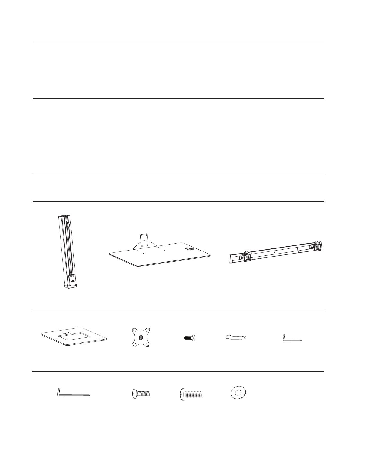
Parts List
(1x)SupportPole(A)
(1x)WeightedBase(D)
(1x)6mmAllenKey(I)
2
(1x)KeyboardTray(B) (1x)MonitorArm(C)
(2x)VESAPlate(E) (8x)Bolt(F)
(4x)Bolt(M-A)
(4x)Bolt(M-B) (4x)Washer(M-C)
(1x)Wrench(G)
(1x)4mmAllenKey(H)
Page 3
Installation
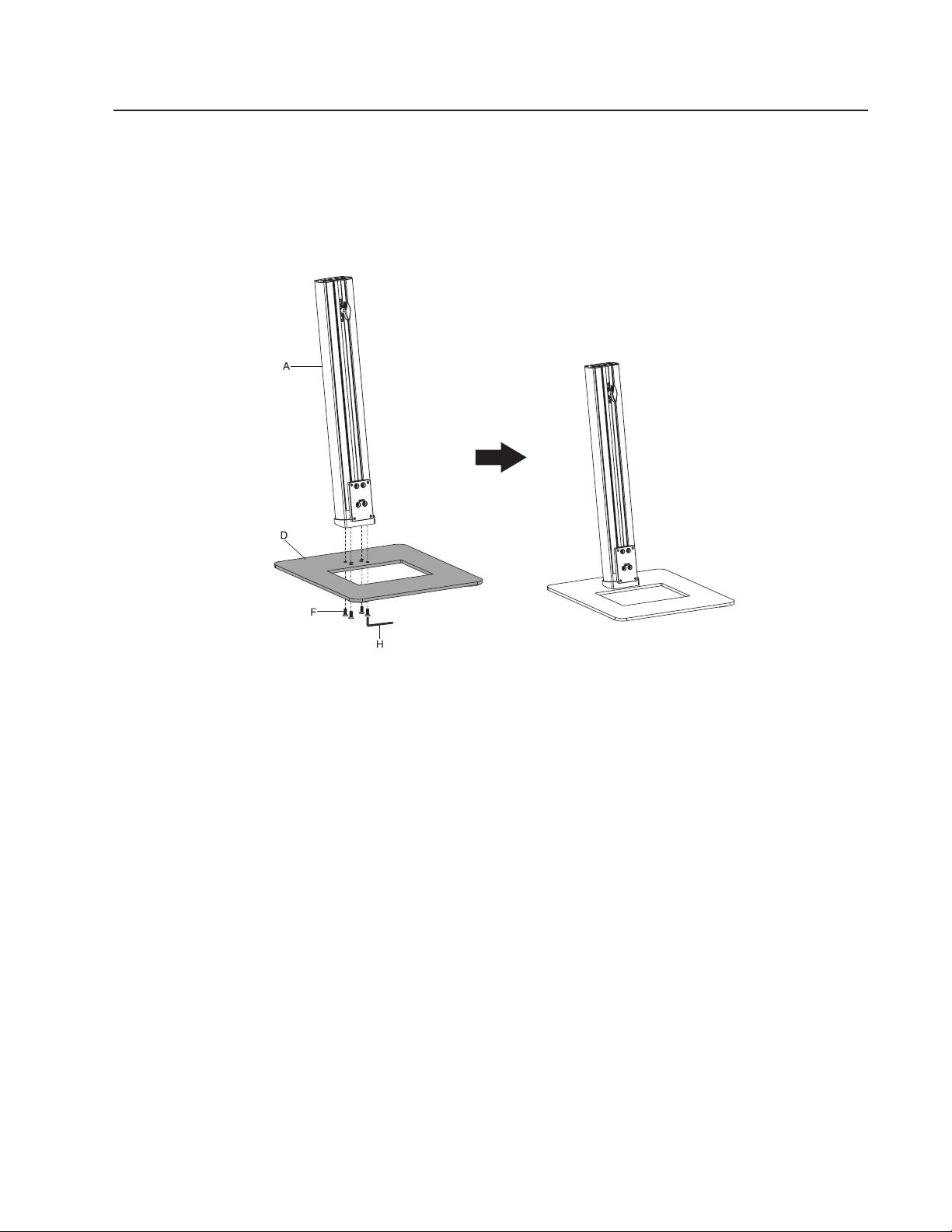
Step 1 - Mount the Support Pole to the Weighted Base
AligntheSupportPole (A)to theWeighted Base(D), insertBolt (F) and tighten them
usingAllenKey(H),seeFigure1.
Figure 1
3
Page 4
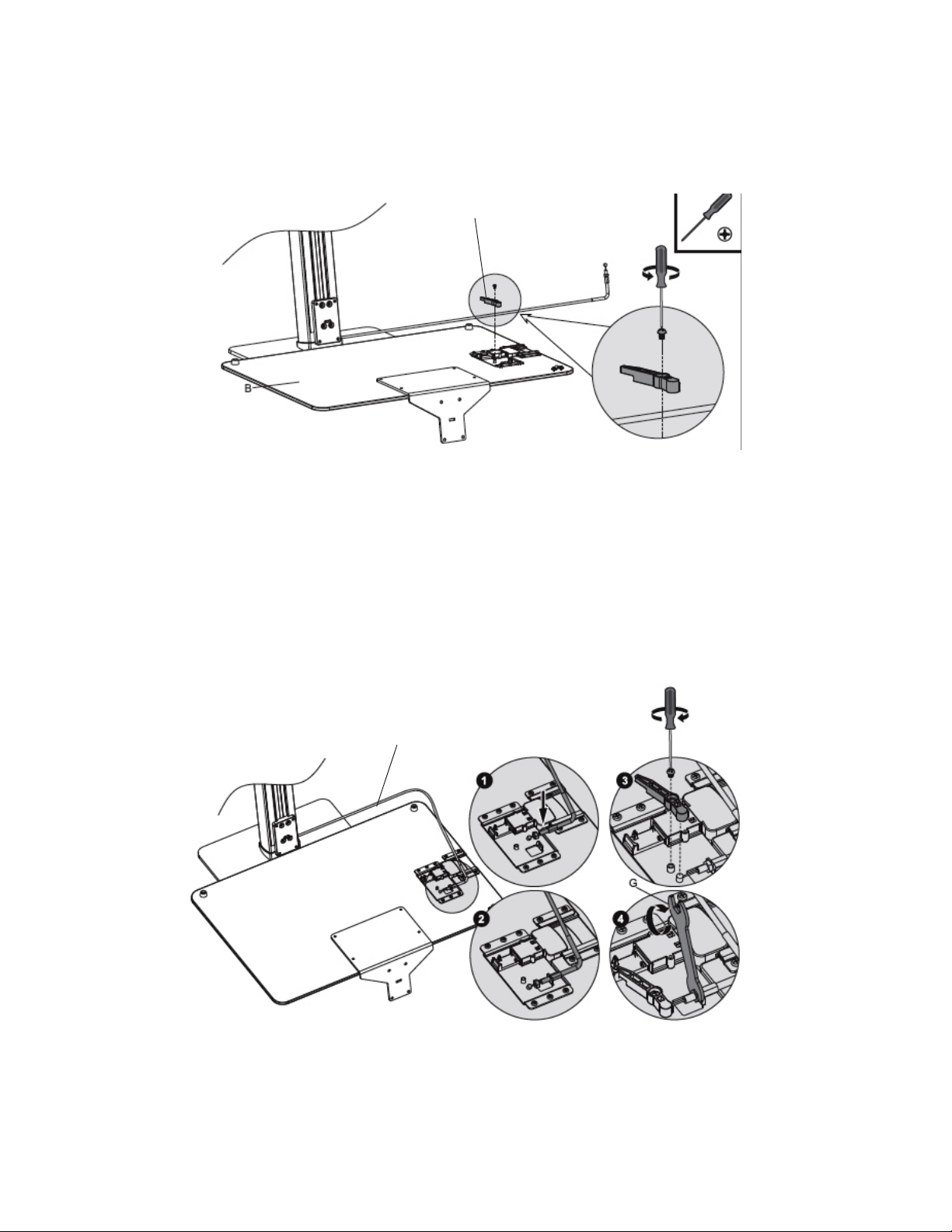
Step 2 - Connect the Height Adjustment Switch
1. TurntheKeyboardTrayoveranduseaPhillipsscrewdrivertoremovethebracket,
seeFigure2A.
Bracket
Figure 2A
2. Findthe SupportPole's WireRod and attachit tothe KeyboardTray, see Figure
2B-1 & 2B-2.
3. Re-installthebracketontotheKeyboardTray,seeFigure2B-3.
4. AdjustthenutusingWrench(G),seeFigure2B-4.
WireRod
Figure 2B
4
Page 5
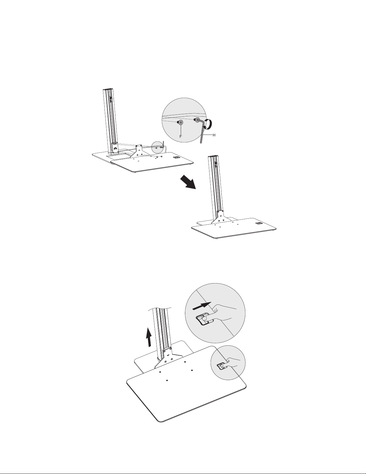
Step 3 - Connect the Keyboard Tray to the Support Pole
1. CarefullyturntheKeyboardTrayover,becarefulnottodamagetheWireRod.
2. Mount the Keyboard Tray to the Support Pole, insert Bolt (F) and tighten using
AllenKey(H),seeFigure3.
Figure 3
2. Slidetheheightadjustmentswitchandraisethekeyboardtray,seeFigure4.
Figure 4
5
Page 6
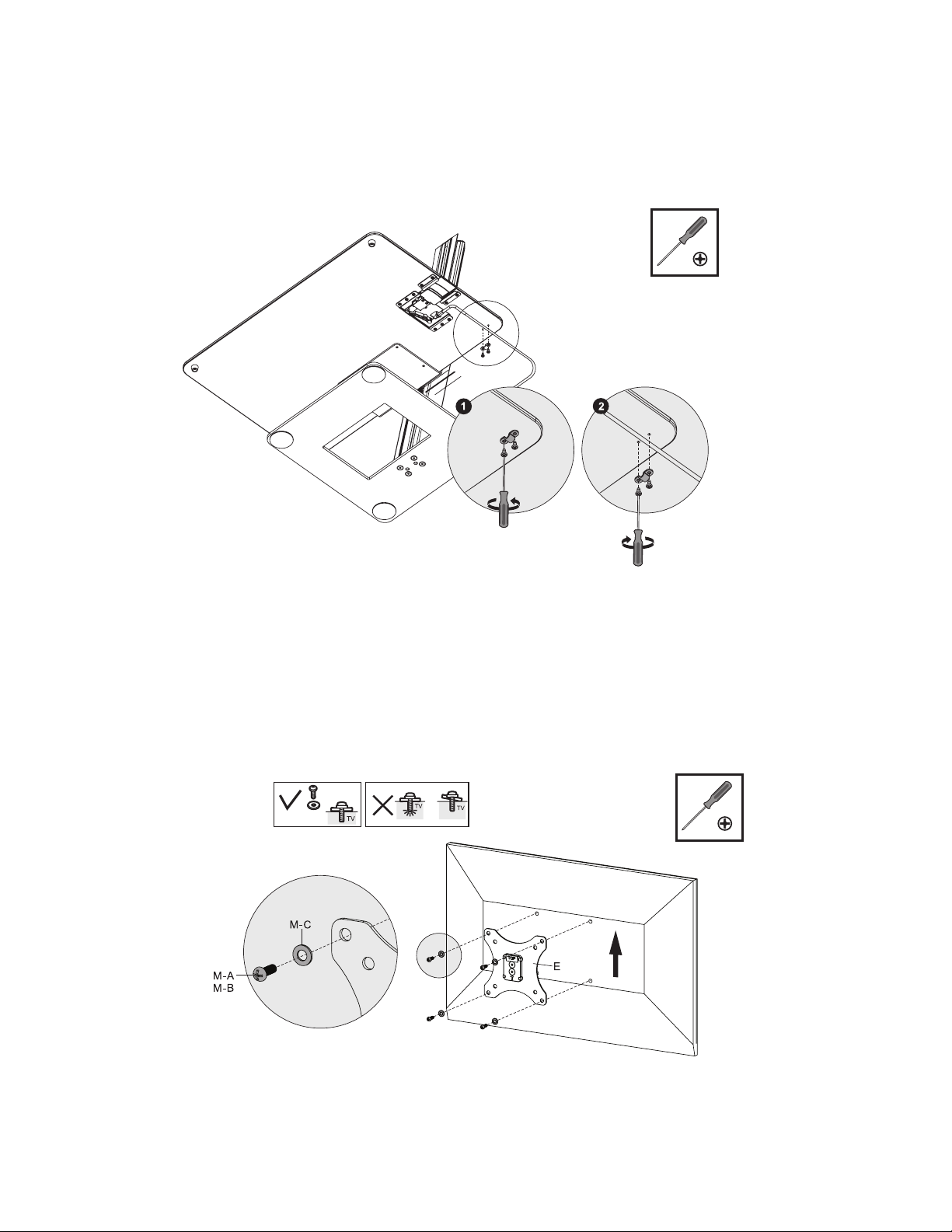
3. Removethebracketfromtheundersideofthekeyboardtrayandplacethewire
rodinthepath,seeFigure5-1.
4. Re-installthebrackettosecurethewirerodtothekeyboardtray,seeFigure5-2.
Note:Thewirerodshouldmovefreely,itisnotintendedtobeinaxedposition.
Figure 5
Step 4 - Mount the VESA Plate to your Monitor
1. TurntheVESAPlatesothat"TOP"facesup,thenmountitontothemonitor.
2. Install Washer (M-C) with Bolt (M-A/M-B) into the monitor's mounting holes,
tightenthemusingaPhillipsscrewdriver,seeFigure6.
Figure 6
6
Page 7
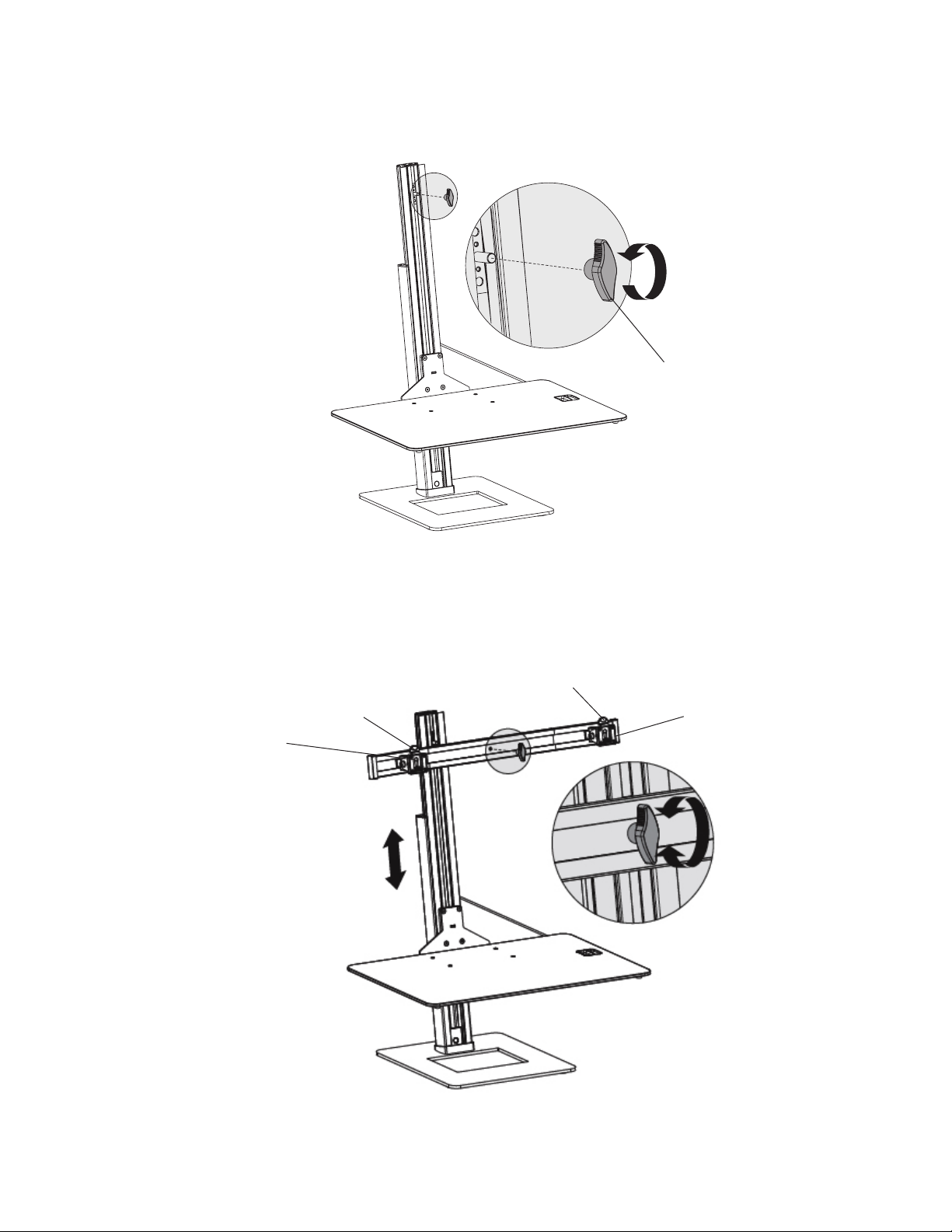
Step 5 - Mount the Monitor Arm and Monitors
1. RemovetheWingNutfromtheSupportPole,seeFigure7.
WingNut
Figure 7
2. MounttheMonitorArmandsecureitwiththeWingNut,seeFigure8.
Note:MakesuretheTabontheVESAplatebracketfacesup.
Tab
Tab VESAPlateBracket
VESAPlateBracket
Figure 8
7
Page 8
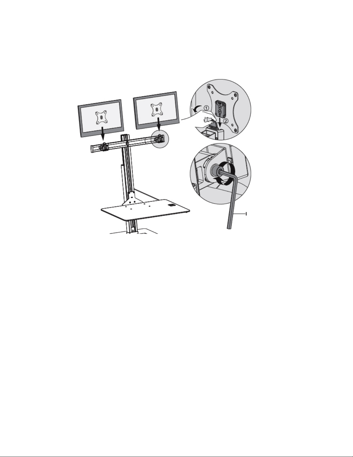
3. Move the Tab back and slide the VESA Plate with Monitor onto the VESA plate
bracket,seeFigure9.
4. Ifnecessary,adjustthetightnessofthetiltanglejointusingAllenKey(I),seeFigure9.
Figure 9
8
Page 9
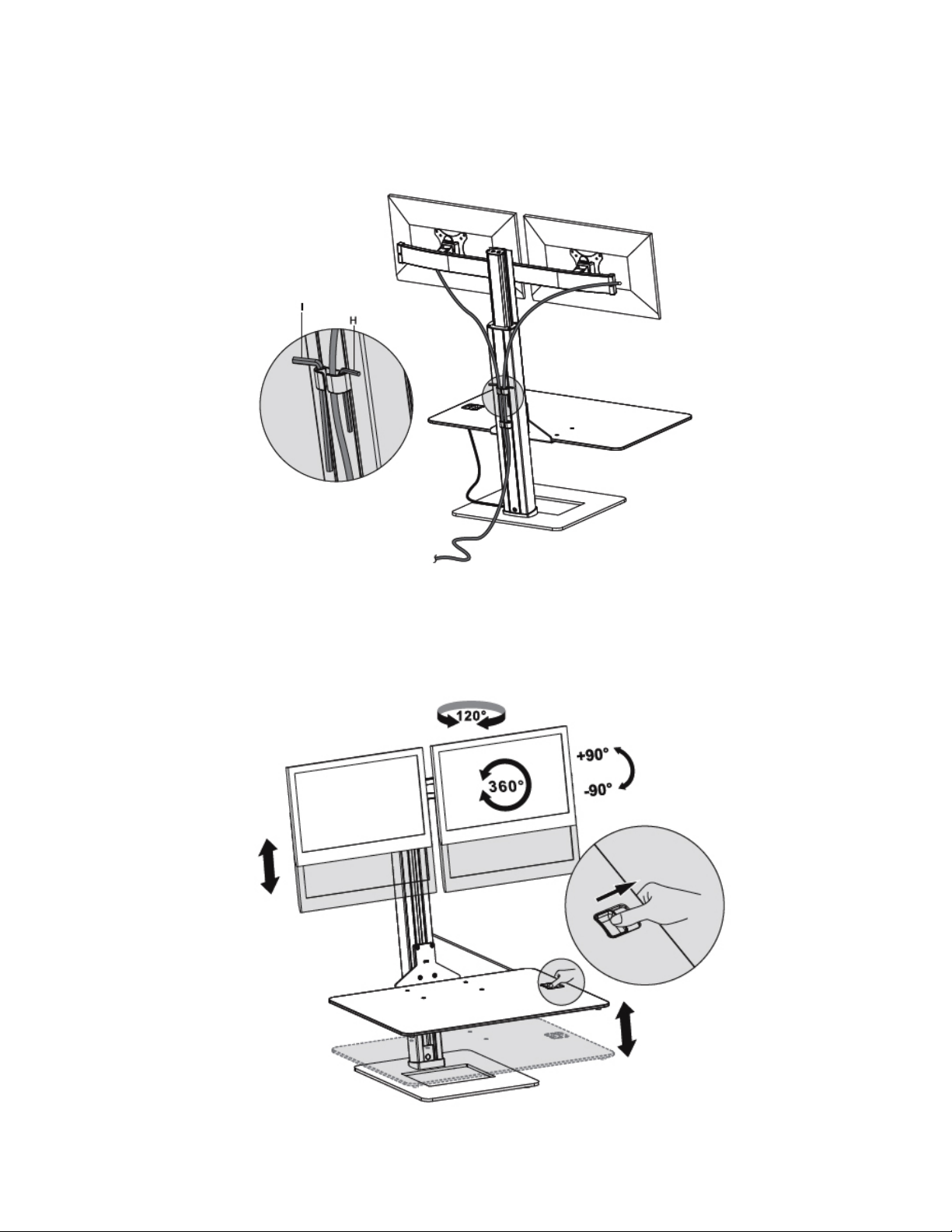
Cable Management and Final Adjustments
1. Route the cables through the wire clips and down the Support Pole, place the
AllenKeysinthewireclipforsafestorage,seeFigure10.
Figure 10
2. Adjustthetiltangle,heightandorientationtothedesiredposition,seeFigure11.
Figure 11
9
Page 10

Maintenance
Check the mounting screws every two months for tightness.
10
Page 11

Blank Page
11
Page 12

Technical Support and Warranty
QUESTIONS?
online support database is updated daily with new drivers and solutions. Answers to your questions could be just a few
clicks away. You can also submit questions online and a technical support analyst will promptly respond.
SIIG offers a 3-year manufacturer warranty with this product. This warranty covers the original purchaser and
guarantees the product to be free of any defects in materials or workmanship for three (3) years from the date of purchase
of the product.
SIIG will, at our discretion, repair or replace (with an identical product or product having similar features and
functionality) the product if defective in materials or workmanship. This warranty gives you specic legal rights, and
you may also have other rights which vary from state to state. Please see our web site for more warranty details.
If you encounter any problems with this product, please follow the procedures below.
A) If it is within the store's return policy period, please return the product to the store where you purchased from.
B) If your purchase has passed the store's return policy period, please follow the steps below to have the product
repaired or replaced.
Step 1:
Go to
request to 510-657-5962. Your RMA request will be processed, if the product is determined to be defective, an RMA
number will be issued.
Step 2:
• Properly pack the product for shipping. All accessories that came with the original package must be included.
• Clearly write your RMA number on the top of the returned package. SIIG will refuse to accept any shipping
package, and will not be responsible for a product returned without an RMA number posted on the outside of the
shipping carton.
• You are responsible for the cost of shipping to SIIG. Ship the product to the following address:
SIIG, Inc.
6078 Stewart Avenue
Fremont, CA 94538-3152, USA
RMA #:
• SIIG will ship the repaired or replaced product via Ground in the U.S. and International Economy outside of the U.S.
at no cost to the customer.
SIIG’s
Submit your RMA request.
www.siig.com
After obtaining an RMA number, ship the product.
Online Support
Support
, click
has answers! Simply visit our web site at
Request A Product Replacement
, then
to submit a request to SIIG RMA or fax a
www.siig.com
and click
Support
. Our
About SIIG, Inc.
Founded in 1985, SIIG, Inc. is a leading manufacturer of IT connectivity solutions (including Serial ATA and Ultra ATA
Controllers, FireWire, USB, and legacy I/O adapters) that bridge the connection between Desktop/Notebook systems
and external peripherals. SIIG continues to grow by adding A/V and Digital Signage connectivity solutions to our
extensive portfolio. All centered around the distribution and switching of A/V signals over CAT5/6, these products
include matrix switches, distribution ampliers, extenders, converters, splitters, cabling, and more.
SIIG is the premier one-stop source of upgrades and is committed to providing high quality products while keeping
economical and competitive prices. High-quality control standards are evident by one of the lowest defective return
rates in the industry. Our products offer comprehensive user manuals, user-friendly features, and most products are
backed by a lifetime warranty.
SIIG products can be found in many computer retail stores, mail order catalogs, and e-commerce sites in the Americas,
as well as through major distributors, system integrators, and VARs.
PRODUCT NAME
DualDisplayAdjustableComputerKeyboardStand
DualDisplay AdjustableComputerKeyboard Stand
SIIG, Inc. All other names used in this publication are for identication only and may be trademarks of their respective owners.
June, 2018 Copyright © 2017 by SIIG, Inc. All rights reserved.
is a trademark of SIIG, Inc. SIIG and the SIIG logo are registered trademarks of
 Loading...