

Page 1
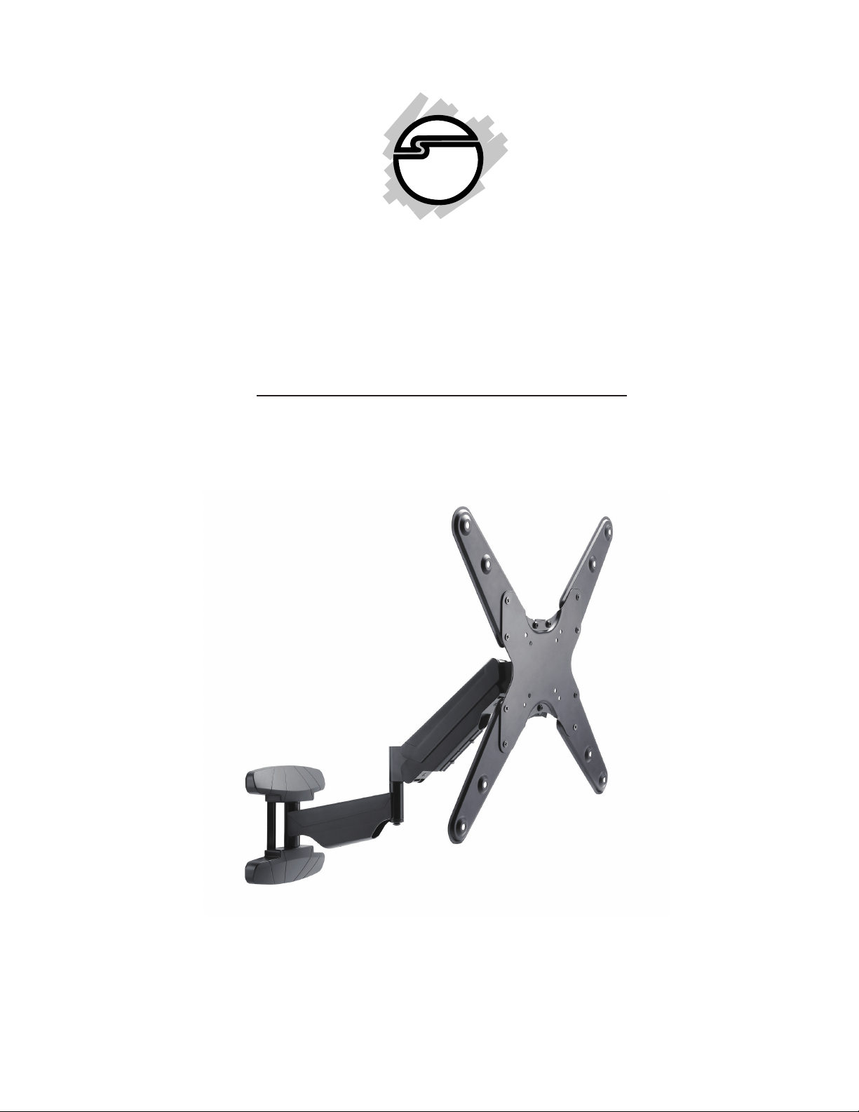
Full Motion Gas Spring TV Wall
Mount - 23" to 55"
Installation Instructions
04-1050B
1
Page 2

Caution
• Prior to installation of this product, the installation instructions should be read and
completely understood. The installation instructions must be read to prevent personal
injury and property damage. Keep these installation instructions in an easily accessible
location for future reference.
• The maximum load capacity is 66 lbs (30 kg). Use with products exceeding the maximum
load capacity may cause serious injury. See apparatus instructions.
• Recommended mounting surfaces: wood stud and solid-flat concrete/brick. If the
mount is to be installed on any surface other than wood studs or solid concrete/brick, use
suitable hardware (not included but commercially available).
• Do not install on a structure that is prone to vibration, movement or chance of impact.
Failure to do so could result in damage to the display and/or damage to the mounting
surface.
• Do not install near heater, fireplace, air conditioning, in direct sunlight or any other heat
producing source. Failure to do so may result in damage to the display and could
increase the risk of fire.
• The wall structure must be capable of supporting at least five (5) times the maximum load
capacity as indicated. If not, the wall must be reinforced.
• Proper installation procedure by yourself or a qualified service technician, as outlined
in the installation instructions, must be adhered to. Failure to do so could result in
serious personal injury.
• When mounting to a wall that contains wood studs, confirm the dead center of the wood
stud prior to installation, it is recommended that the wood studs be a minimum of 16"
apart (if applicable).
• It is recommended that two people perform the installation. Personal injury and/or
property damage can result from dropping or mishandling the display.
Unpacking
• Carefully remove the contents and lay them out on cardboard or other protective surface
• Check package contents against the parts list to ensure that all components were received
and undamaged. Do not use damaged or defective parts
• Carefully read all instructions before attempting the installation
Safety Information
• Use proper safety equipment during installation
• If you don't understand the installation instructions, please consult an installation
specialist
• This stand contains small parts which can act as a choking hazard if swallowed
• Do not use this product for any purpose or in any configuration not explicitly specified
in these instructions
2
Page 3
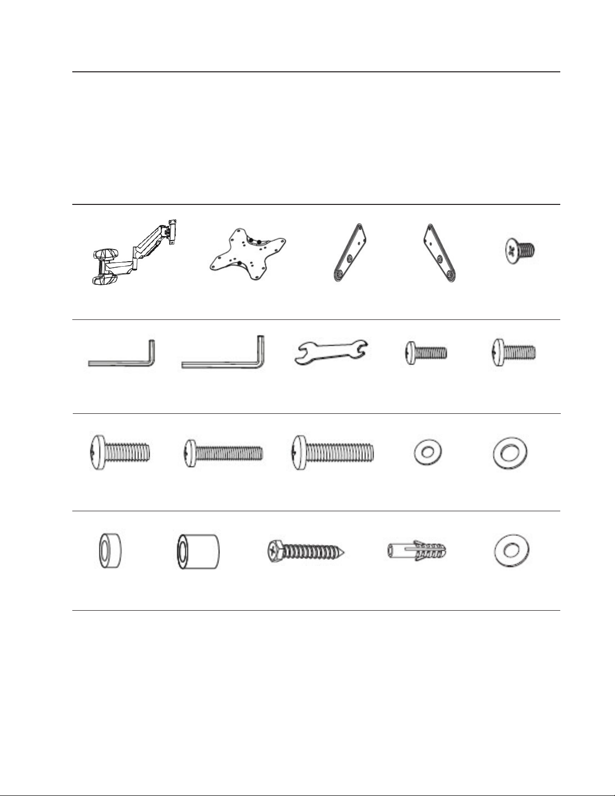
Tools Required
• Phillips screwdriver
• Electronic stud finder
• Bubble level
• Electric drill
• 3/16" drill bit (wood stud installation)
• 3/8" masonry drill bit, hammer (concrete/brick installation)
Parts List
A - (1x) Extension Arm
F - (1x) 4mm Allen Key
M-C - (4x) M8x20 Bolt
M-H - (8x) Spacer M-I - (4x) Wide Spacer W-C - (4x) Washer
B - (1x) VESA Plate C - (2x) VESA Plate Extender
G - (1x) 6mm Allen Key
M-D - (4x) M6x30 Bolt
W-A - (5x) Screw
H - (1x) Wench M-B - (4x) M6x14 Bolt
M-E - (4x) M8x30 Bolt
D - (2x) VESA Plate Extender
M-A - (4x) M5x14 Bolt
M-F - (4x) D5 Washer
W-B - (5x) Concrete Anchor
E - (8x) Screw
M-G - (4x) D8 Washer
3
Page 4
Installation
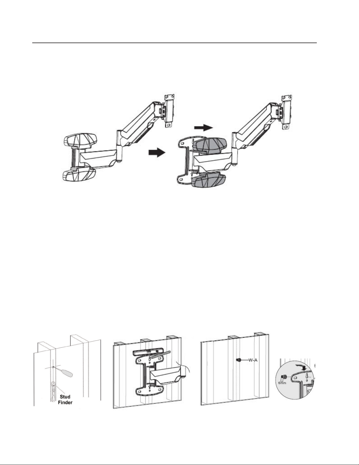
Step 1 - Remove the Decorative Covers from the Wall Plate
1. Place both hands on the decorative cover, gently squeeze to remove it from the wall plate,
see Figure 1.
2. Remove the 2nd decorative cover using the same method.
Figure 1
Step 2 - Wall Plate Installation
2A) Wood Stud Installation
1. Use a high quality electronic stud finder (commercially available) to locate dead center
of a wood stud and mark the location with a pencil, see Figure 2A-1.
2. Hold the wall plate to the wall, line up the top mounting hole to dead center of the wood
stud, and mark the location to be used for mounting the wall plate to the wall, see Figure
2A-2.
3. Take down the wall plate and drill a 2.2" deep hole, using a 3/16" drill bit, at the position
you've marked. Insert Screw (W-A) into the drilled hole and with a Phillips screwdriver
turn it clockwise to tighten, leave a gap of 6mm from fully tight, see Figure 2A-3.
Figure 2A-1 Figure 2A-2 Figure 2A-3
4
Page 5
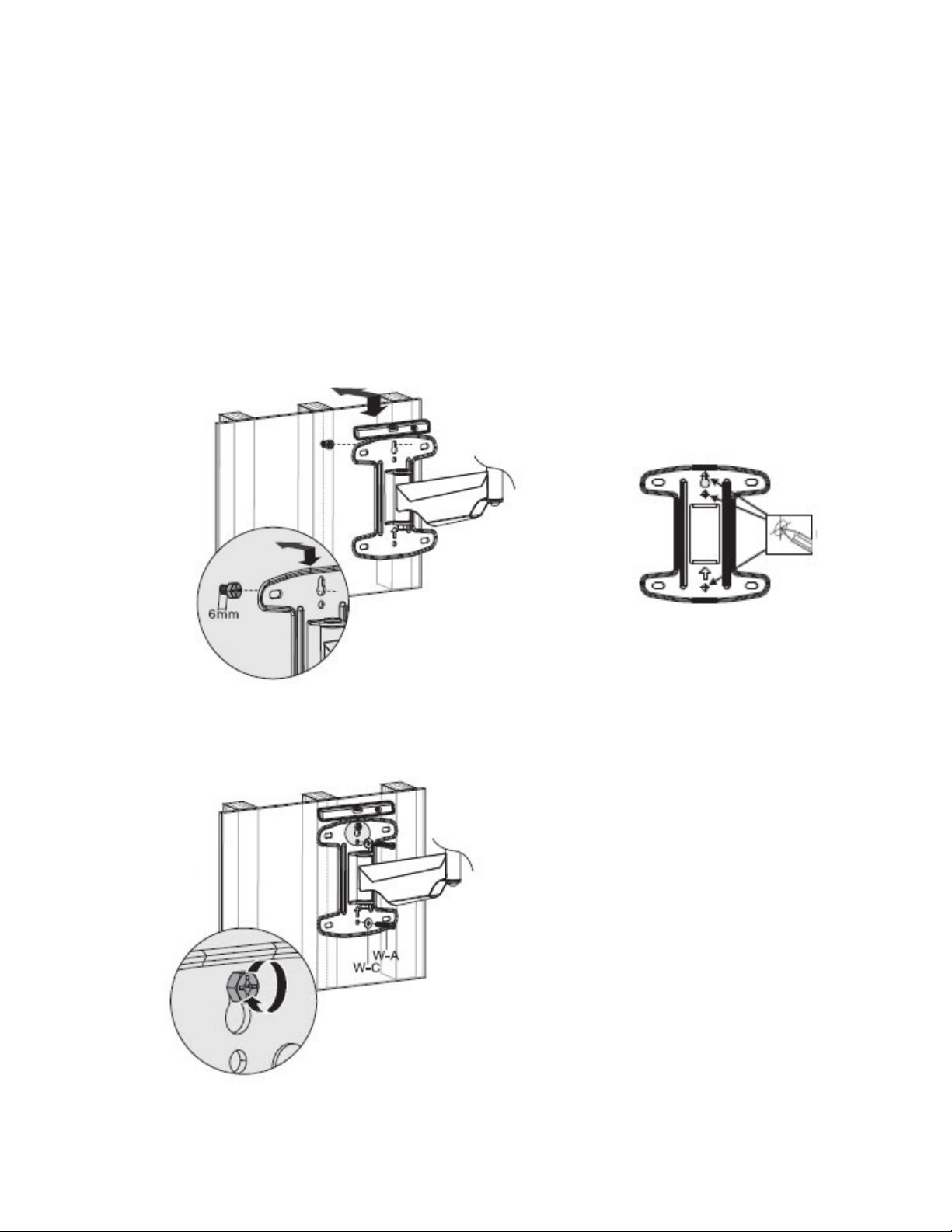
4. Place the wall plate to the wall, insert the top mounting hole onto the mounted screw, see
Figure 2A-4.
5. Line up center mounting holes to dead center of the wood stud, use a bubble level to
verify that the wall plate is level, then mark the 2 locations, see Figure 2A-5.
6. Take down the wall plate and drill a 2.4" deep hole, using a 3/16" drill bit, at the locations
you've marked.
7. Place the wall plate to the wall again, line up the mounting holes, use a bubble level to
verify that the wall plate is level.
8. For each location insert Screw (W-A) and Washer (W-C) into the wall, see Figure 2A-6.
9. Tighten each screw with a Phillips screwdriver by turning clockwise until fully tight.
Figure 2A-4
Figure 2A-5
Figure 2A-6
5
Page 6
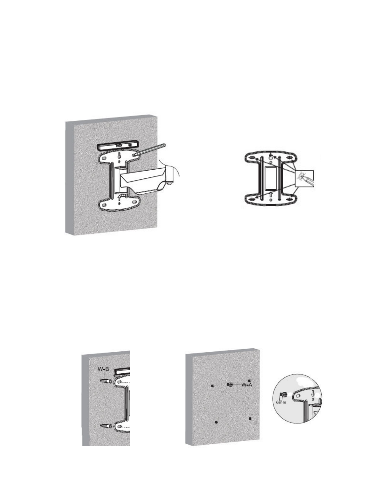
2B) Concrete / Brick Installation
Note: The concrete anchors must be used for concrete and brick installation.
1. Place the wall plate onto the wall in the desired mounting location, check the bubble level
to ensure it is level, see Figure 2B-1.
2. Mark 5 holes to be used for securing the wall plate, and place the wall plate aside, see
Figure 2B-2. Note: Locate the holes directly into the concrete or brick, never into the
mortar between the blocks.
Figure 2B-2
Figure 2B-1
3. Drill a 2.4" deep hole, using a 3/8" masonry drill bit, at the positions you've marked.
4. Insert a Concrete Anchor (W-B) into each hole, see Figure 2B-3.
5. If necessary, a hammer can be used to lightly tap each concrete anchor into place so that
they are flush with the wall.
6. Once all of the concrete anchors are in place, insert Screw (W-A) into the top center
concrete anchor, and with a Phillips screwdriver turn it clockwise to tighten, leave a gap
of 6mm from fully tight, see Figure 2B-4.
Figure 2B-3 Figure 2B-4
6
Page 7
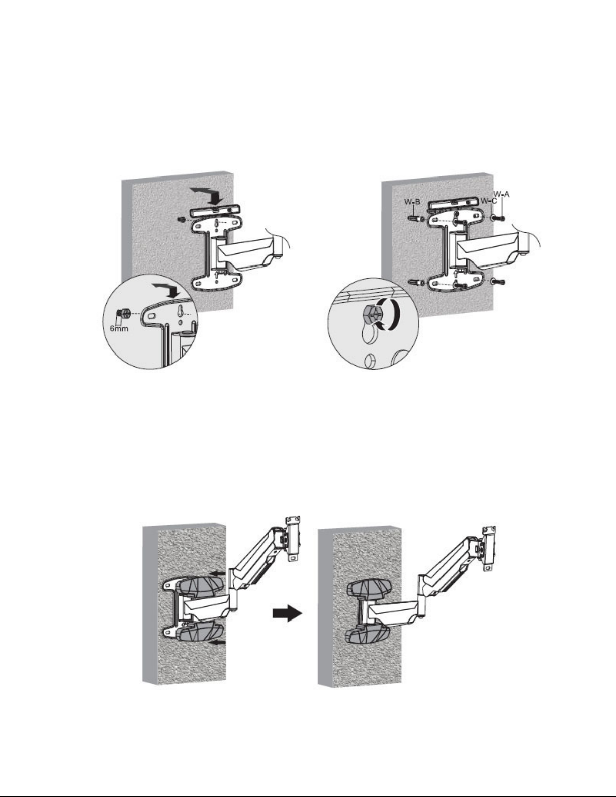
7. Place the wall plate to the wall, insert the top center mounting hole onto the mounted
screw, see Figure 2B-5.
8. Line up the mounting holes with the concrete anchors. Check with a bubble level to verify
that the wall plate is level.
9. Insert Screw (W-A) and Washer (W-C) into each concrete anchor. Tighten all screws with
a Phillips screwdriver by turnining clockwise until fully tight, see Figure 2B-6.
Figure 2B-5
Figure 2B-6
Step 3 - Reinstall the Decorative Covers
1. Align the decorative cover to the wall plate and carefully press until it snaps into place,
see Figure 3.
Figure 3
7
Page 8
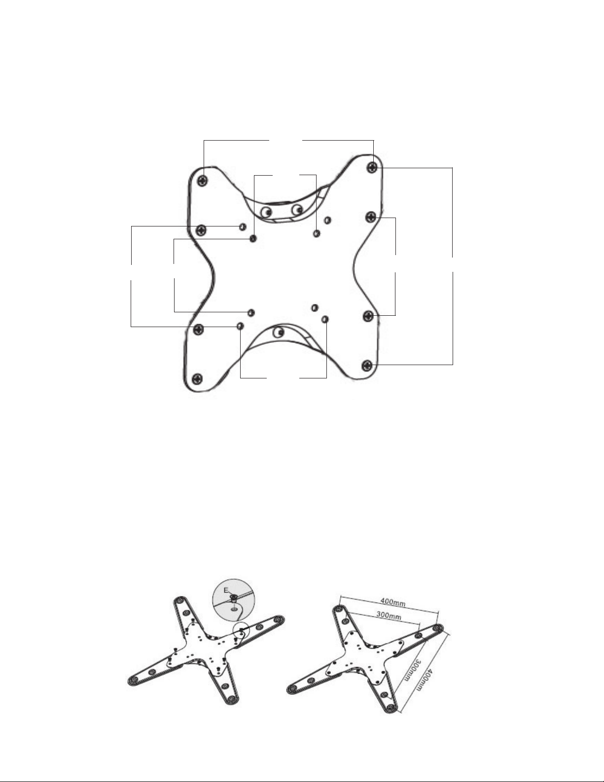
Step 4 - Select the VESA Plate Mounting Pattern to Match your TV
The VESA Plate fits VESA mounting pattern 75x75,100x100, 200x100 and 200x200. For a TV
with different mounting pattern, add the VESA Plate Extender as shown below.
VESA Mounting Pattern: 75x75mm / 100x100mm / 200x100mm / 200x200mm
200mm
75mm
100mm
75mm
100mm
100mm
VESA Plate
200mm
Follow the Below Steps to Install the VESA Plate Extender onto the VESA Plate for
the VESA Mounting Patterns as Shown
1. Determine the VESA mounting pattern of your TV.
2. Install the VESA Plate Extender to the VESA Plate in the position shown.
3. Use Bolt (E) and tighten with a Phillips screwdriver to secure the extender to the VESA
Plate.
VESA Mounting Pattern: 300x300 / 400x400
8
Page 9
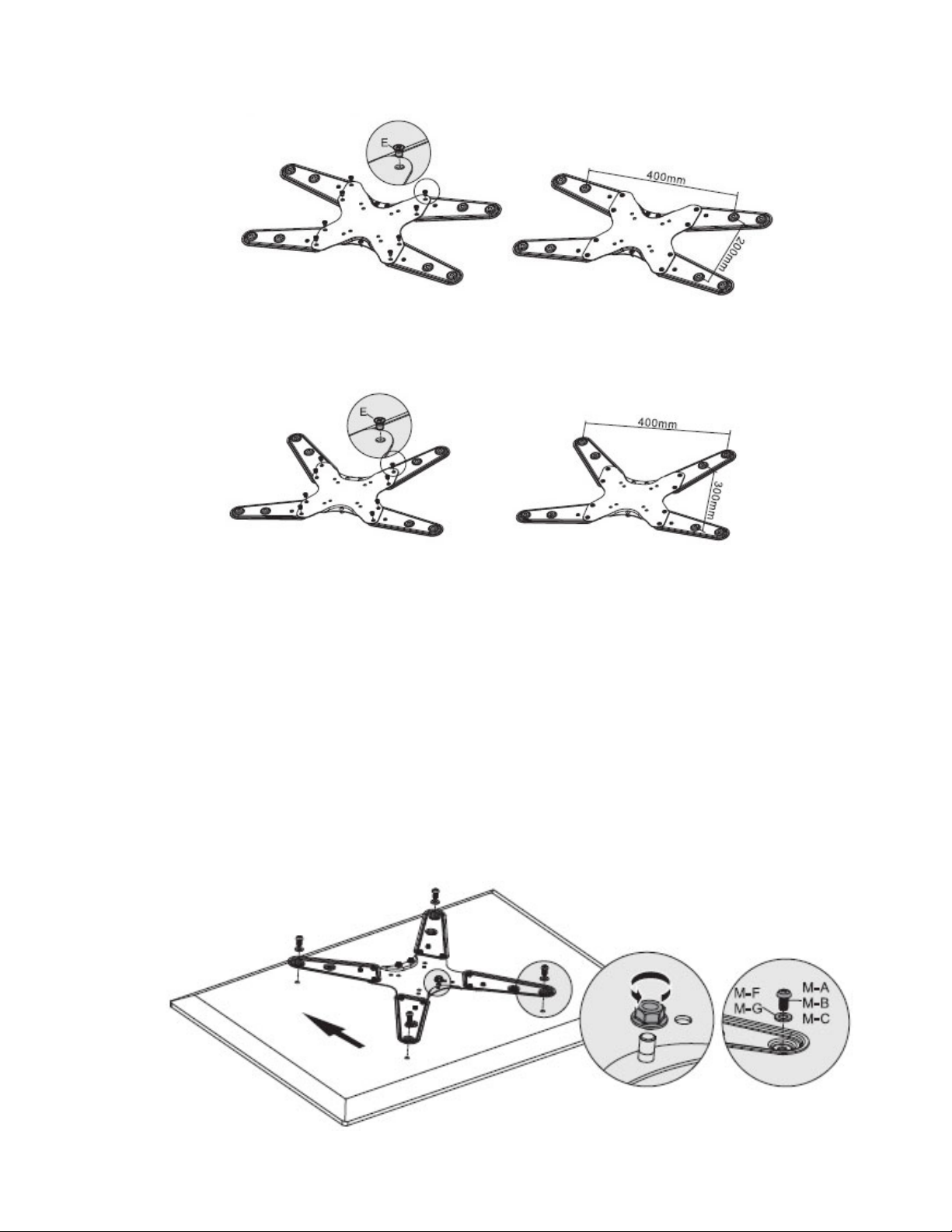
VESA Mounting Pattern: 400x200
VESA Mounting Pattern: 400x300
Step 5 - Install the VESA Plate to the TV
Mounting the VESA Plate to a TV with a Flat Back
1. Place your TV screen side down on a soft flat surface, and locate the threaded mounting
holes that are located on the back of the TV.
2. Determine the depth of the mounting holes by inserting a straw or toothpick. Select the
Bolt (M-A, M-B, M-C) with the correct depth and diameter of the mounting holes of your
TV.
3. Thread the bolts into the TV using the correct Washer (M-F, M-G), then tighten them with
a Phillips screwdriver by turning clockwise until fully tight, see Figure 4 & 4B.
4. Remove the mounting nut from the VESA plate by turning it counterclockwise, set it
aside for later use, see Figure 4A.
Figure 4
Figure 4A Figure 4B
9
Page 10
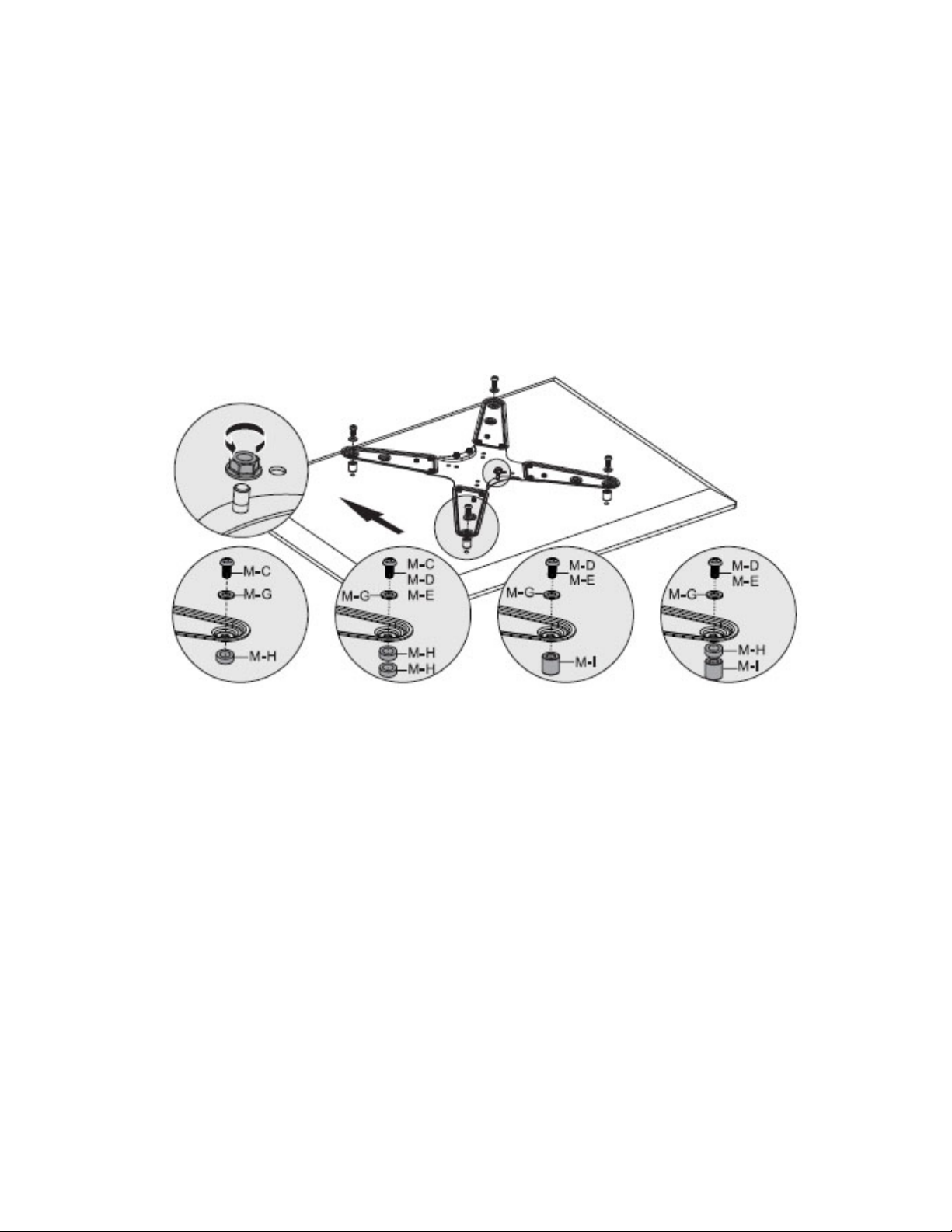
Mounting the VESA Plate to a TV with a Curved Back
1. Place your TV screen side down on a soft flat surface, and locate the threaded mounting
holes that are located on the back of the TV.
2. Determine the depth of the mounting holes by inserting a straw or toothpick. Select the
Bolt (M-C, M-D, M-E) with the correct depth and diameter of the mounting holes of your
TV.
3. Thread the bolts into the TV using the correct Washer (M-G) and Spacer (M-H, M-I), then
tighten them with a Phillips screwdriver by turning clockwise until fully tight, see
Figure 5.
4. Remove the mounting nut from the VESA plate by turning it counterclockwise, set it
aside for later use, see Figure 5A.
Figure 5A
Figure 5
10
Page 11
Step 5 - Attaching the TV to the Extension Arm
Warning: Some TVs may require two people to lift and position it onto the extension arm. SIIG,
Inc. is NOT RESPONSIBLE for any damage or injury caused by incorrect installation,
assembly or use.
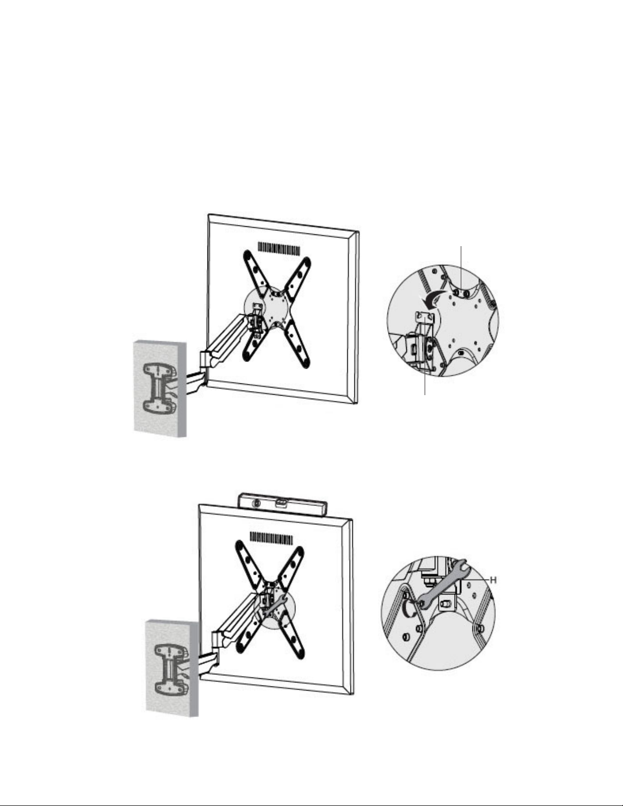
1. Hang the TV with VESA plate assembly onto the top of the extension arm bracket, then
let the bottom of the VESA plate rotate to the bottom of the bracket, see Figure 6. Note:
if needed, loosen the 2 mounting nuts slightly for easier installation.
2. Replace the mounting nut removed earlier, and tighten all mounting nuts with
Wrench (H) by turning them clockwise until fully tight, see Figure 7.
Mounting Nuts
Figure 6
Extension Arm Bracket
Figure 7
11
Page 12
Step 6 - Gas Spring Adjustment
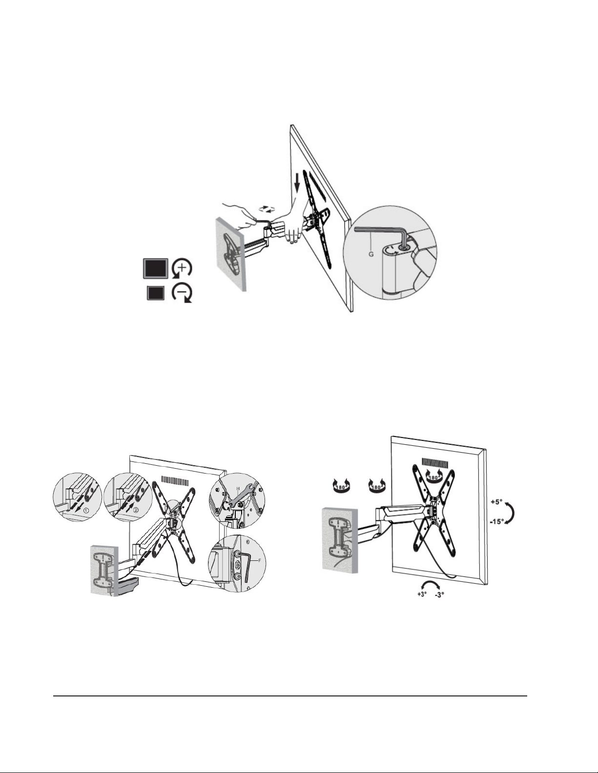
1. Adjust the tension of the Gas Spring using 4mm Allen Key (G), see Figure 8.
2. Turn it clockwise to decrease the tension for lighter monitors, or turn it counterclockwise
to increase the tension for heavier monitors.
Figure 8
Step 7 - Final Installation
1. Route the cables from your TV through the cable management system, see Figure 9.
2. Adjust the tilt angle with Allen Key (F), see Figure 9A.
3. Adjust the level of the TV using Wrench (H) to loosen the mounting nuts, see Figure 9B.
4. Place the monitor intto the optimal viewing angle, see Figure 10.
Figure 9B
Figure 9
Figure 9A
Figure 10
Maintenance
Check the mounting hardware every two months for tightness.
12
Page 13

Blank Page
13
Page 14

Blank Page
14
Page 15

Blank Page
15
Page 16

Technical Support and Warranty
QUESTIONS? SIIG’s Online Support has answers! Simply visit our web site at www.siig.com and click Support. Our online
support database is updated daily with new drivers and solutions. Answers to your questions could be just a few clicks away.
You can also submit questions online and a technical support analyst will promptly respond.
SIIG offers a 3-year manufacturer warranty with this product. This warranty covers the original purchaser and guarantees
the product to be free of any defects in materials or workmanship for three (3) years from the date of purchase of the product.
This warranty is not transferable and is available only to the original purchaser of the product.
SIIG will, at our discretion, repair or replace (with an identical product or product having similar features and functionality)
the product if defective in materials or workmanship. This warranty gives you specific legal rights, and you may also have
other rights which vary from state to state. Please see our web site for more warranty details.
If you encounter any problems with this product, please follow the procedures below.
A) If it is within the store's return policy period, please return the product to the store where you purchased it.
B) If your purchase has passed the store's return policy period, please follow these steps to have the product repaired or
replaced.
Step 1: Submit your RMA request. Go to www.siig.com, click Support, then Request A Product Replacement to submit
a request to
to be defective, an RMA number will be issued.
Step 2: After obtaining an RMA number, ship the product.
• Properly pack the product for shipping. All software, cable(s) and any other accessories that came with the original
package must be included
• Include a copy of your original sales receipt inside the package with the date of purchase and place of purchase circled
and clearly visible
• Clearly write your RMA number on the top of the returned package. SIIG will refuse to accept any shipping package,
and will not be responsible for a product returned without an RMA number posted on the outside of the shipping
carton
• You are responsible for the cost of shipping to SIIG. Ship the product to the following address:
SIIG, Inc.
6078 Stewart Avenue
Fremont, CA 94538-3152, USA
RMA #:
• SIIG will ship the repaired or replaced product via Ground in the U.S. and International Economy outside of the U.S.
at no cost to the customer
SIIG RMA or fax a request to 510-657-5962. Your RMA request will be processed, if the product is determined
About SIIG, Inc.
Founded in 1985, SIIG, Inc. is a leading manufacturer of IT connectivity solutions (including Serial ATA and Ultra ATA
Controllers, FireWire, USB, and legacy I/O adapters) that bridge the connection between Desktop/Notebook systems and
external peripherals. SIIG continues to grow by adding A/V and Digital Signage connectivity solutions to our extensive
portfolio. All centered around the distribution and switching of A/V signals over CAT5/6, these products include matrix
switches, distribution amplifiers, extenders, converters, splitters, cabling, and more.
SIIG is the premier one-stop source of upgrades and is committed to providing high quality products while keeping
economical and competitive prices. High-quality control standards are evident by one of the lowest defective return rates
in the industry. Our products offer comprehensive user manuals, user-friendly features and are backed by an extensive
manufacturer warranty.
SIIG products can be found in many computer retail stores, mail order catalogs, and e-commerce sites in the Americas, as
well as through major distributors, system integrators, and VARs.
PRODUCT NAME
Full Motion Gas Spring TV Wall Mount - 23" to 55"
Full Motion Gas Spring TV Wall Mount - 23" to 55" is a trademark of SIIG, Inc. SIIG and the SIIG logo are registered trademarks of SIIG,
Inc. All other names used in this publication are for identification only and may be trademarks of their respective owners.
November, 2016 Copyright © 2016 by SIIG, Inc. All rights reserved.
 Loading...