

Page 1
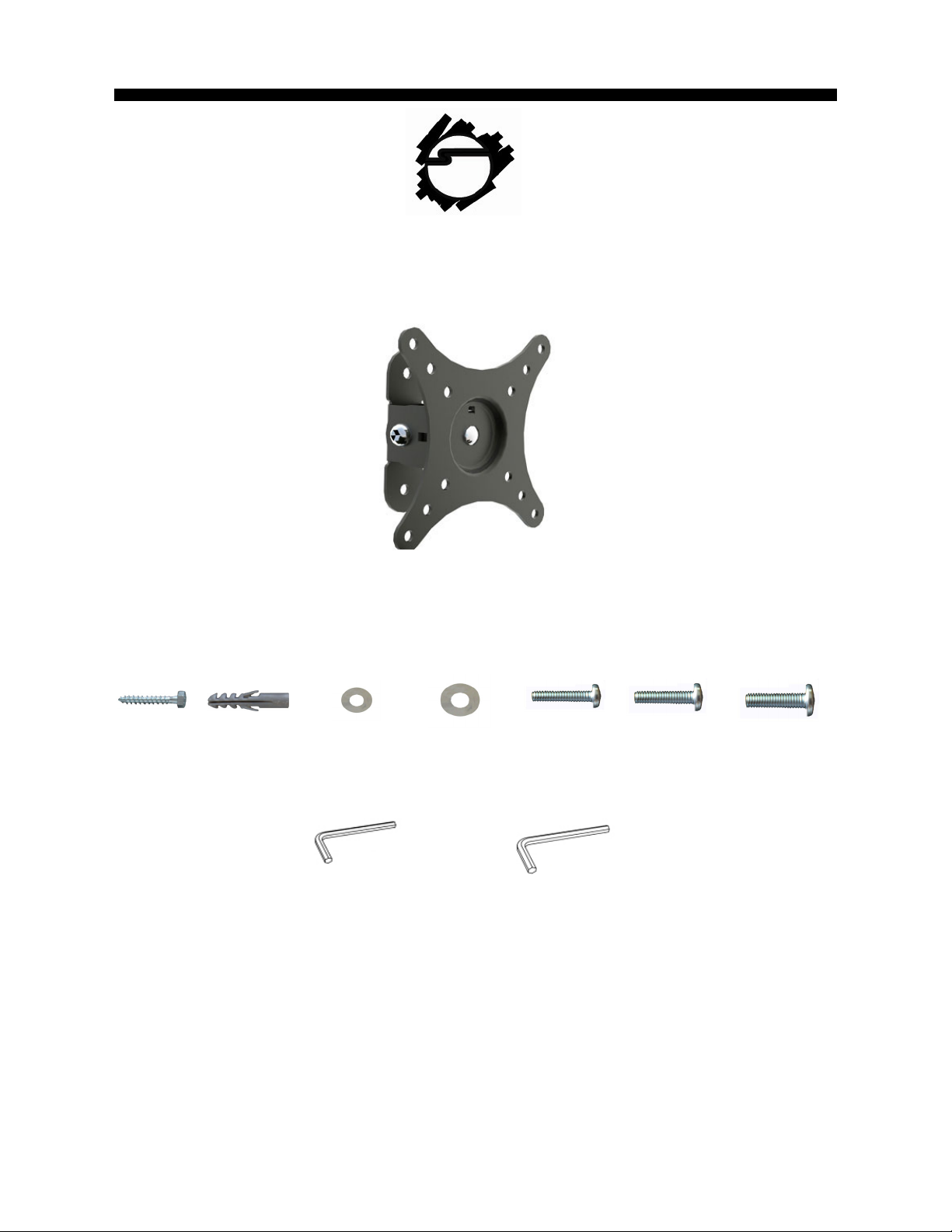
LCD TV/Monitor Tilting Mount - 10" to 26"
Installation Instructions
Hardware
A B C D E F G
(x2) M6X60
bolt
(x2) M6 concrete
anchor
(x4) M6 small
washer
4mm Allen Key 6mm Allen Key
(x2) M6 large
washer
(x4) M4X12
screw
(x4) M5X12
screw
(x4) M6X12
screw
Tools Required: Electronic stud finder, #2 Phillips head screw driver, drill, 1/8" drill bit (wood
stud installation), 3/8" masonry drill bit (concrete/brick wall installation).
04-0553C
Page 1
Page 2
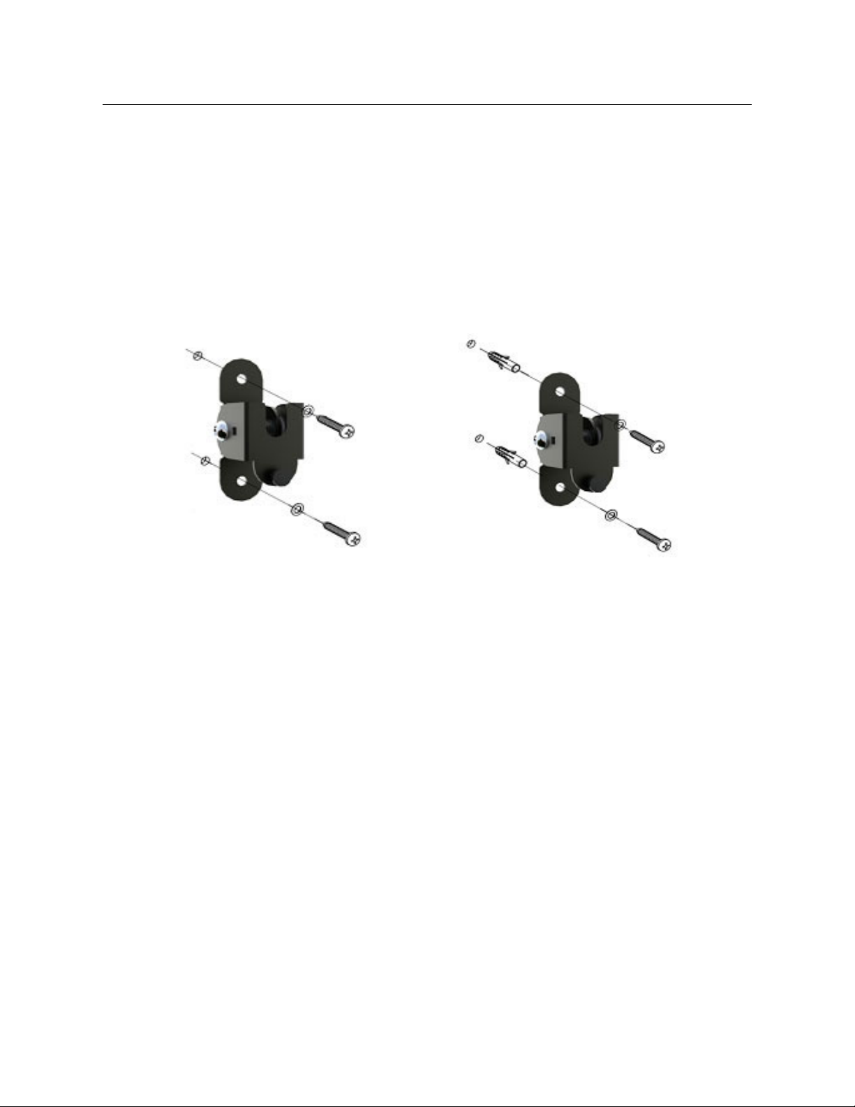
Step 1: Wall Plate Installation
Wood Stud Installation
Use a high-quality electronic stud finder (commercially available) to locate dead center
1
of the wood stud and mark the location with a pencil.
Hold the wall plate (Figure 1) to the wall, use the two mounting holes to mark the
2
locations to be used for mounting the wall plate.
Take down the wall plate and drill two 2" deep holes, using a 1/8" drill bit at the
3
positions you've marked.
Attach the wall plate to the wall again and insert the bolts (A) and washers (D) into the
4
holes (Figure 1) and tighten.
Figure 1 Figure 2
Concrete/Brick Wall Installation
1
Hold the wall plate (Figure 2) to the wall, use the two mounting holes to mark the
locations to be used for mounting the wall plate. Locate the holes directly into the
brick, block or concrete, never into the mortar between the blocks.
Pre-drill two holes to a depth of 2" using a 3/8" masonry drill bit at the positions you've
2
marked and insert one concrete anchor (B) into each hole.
Position the wall plate onto the wall again and insert the bolts (A) and washer (D) into
3
the anchor as shown (Figure 2) and tighten.
Page 2
Page 3
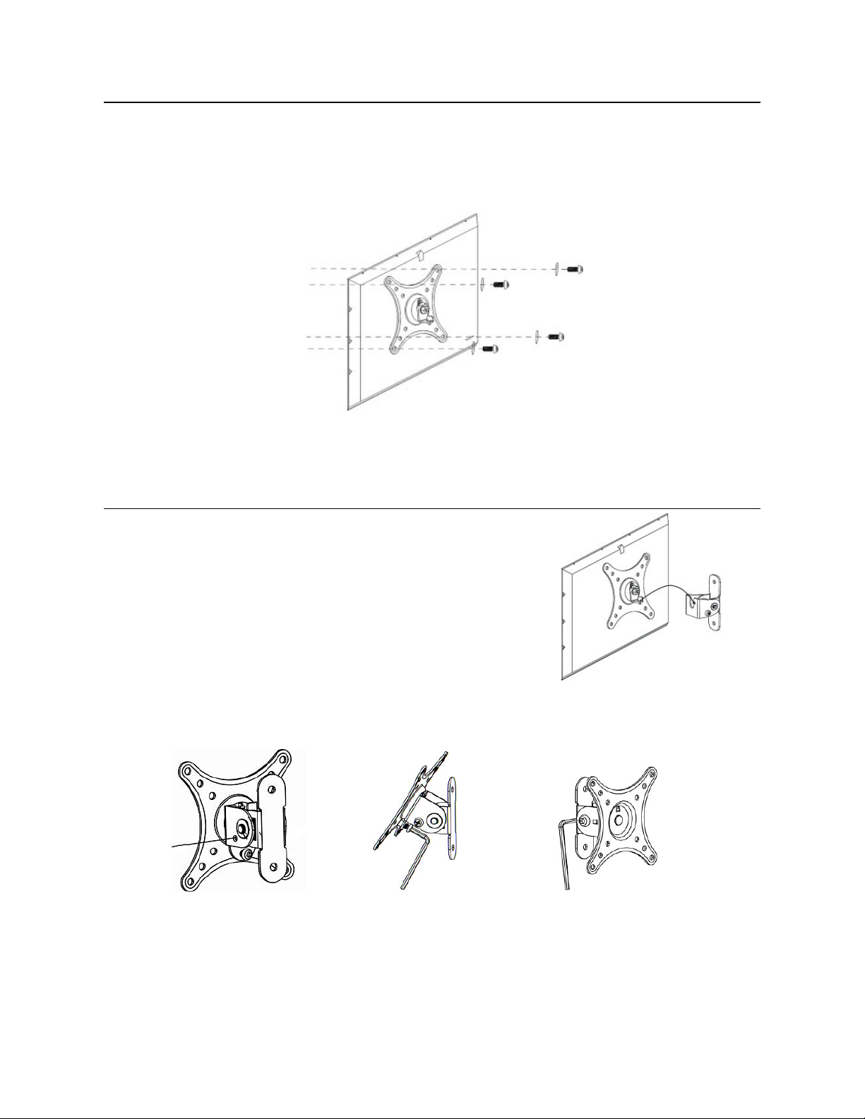
Step 2: Display Plate Installation
1
Place your TV screen down on a soft, flat surface, and locate the threaded mounting
points that are located on the back of the display.
According to the size of the display's hole, choose the corresponding screw (E/F/G)
2
and washer (C) and insert into the hole as shown (Figure 3) and tighten.
Step 3: Final Installation
Hang the display plate onto the top of the
1
wall plate and slip it into the wall plate as
shown (Figure 4).
Figure 3
2
3
Phillips
screw driver
Tighten the safety screw on the side and
back using a Phillips head screw driver
and the supplied 4mm Allen Key (Figure 5
& Figure 6 respectively).
Adjust the tension of the joint using the
supplied 6mm Allen Key (Figure 7).
Figure 4
Figure 5 Figure 6 Figure 7
Page 3
Page 4

Maintenance
Check the mounting screws every two months for tightness.
Important: If you don't understand the installation instructions, please consult an
installation specialist.
Page 4
Page 5

Blank Page
Page 5
Page 6

Blank Page
Page 6
Page 7

Technical Support and Warranty
QUESTIONS? SIIG’s Online Support has answers! Simply visit our web site at www.siig.com
and click Support. Our online support database is updated daily with new drivers and solutions.
Answers to your questions could be just a few clicks away. You can also submit questions
online and a technical support analysts will promptly respond.
SIIG offers a 5-year manufacturer warranty with this product. This warranty covers the original
purchaser and guarantees the product to be free of any defects in materials or workmanship for
five (5) years from the date of purchase of the product.
SIIG will, at our discretion, repair or replace (with an identical product or product having similar
features and functionality) the product if defective in materials or workmanship. This warranty
gives you specific legal rights, and you may also have other rights which vary from state to state.
Please see our web site for more warranty details.
If you encounter any problems with this product, please follow the procedures below.
A) If it is within the store's return policy period, please return the product to the store where you
purchased from.
B) If your purchase has passed the store's return policy period, please follow these steps to
have the product repaired or replaced.
Step 1: Submit your RMA request.
Go to www.siig.com, click Support, then click RMA to submit an request to SIIG RMA or fax a
request to 510-657-5962. If the product is determined to be defective, an RMA number will be
issued.
Step 2: After obtaining an RMA number, ship the product.
• Properly pack the product for shipping. All software, cable(s) and any other accessories that
came with the original package must be included.
• Clearly write your RMA number on the top of the returned package. SIIG will refuse to accept
any shipping package, and will not be responsible for a product returned without an RMA
number posted on the outside of the shipping carton.
• You are responsible for the cost of shipping. Ship the product to the following address:
SIIG, Inc.
6078 Stewart Avenue
Fremont, CA 94538-3152, USA
RMA #: ________________
• SIIG will ship the repaired or replaced product via Ground in the U.S. and International
Economy outside of the U.S. at no cost to the customer.
Page 7
Page 8

About SIIG, Inc.
Founded in 1985, SIIG, Inc. is a leading computer upgrade manufacturer of I/O connectivity
products, including PCI & ISA serial and parallel ports, USB, Serial ATA & UltraATA controllers,
FireWire (1394a/b), networking, sound cards, and other accessories. SIIG is the premier onestop source of upgrades. SIIG products offer comprehensive user manuals, many user-friendly
features, and are backed by an extensive manufacturer warranty. High-quality control standards
are evident by the overall ease of installation and compatibility of our products, as well as one of
the lowest defective return rates in the industry. SIIG products can be found in computer retail
stores, mail order catalogs, through major distributors, system integrators, and VARs in the
Americas and the UK, and through e-commerce sites.
Product Name
LCD TV/Monitor Tilting Mount - 10" to 26"
LCD TV/Monitor Tilting Mount - 10" to 26" is a trademark of SIIG, Inc. SIIG and the SIIG logo are registered trademarks of
SIIG, Inc. Other names used in this publication are for identification only and may be trademarks of their respective companies.
September, 2010 Copyright © 2010 by SIIG, Inc. All rights reserved.
Page 8
 Loading...