

Page 1

AP-10 SCSI PCI
TM
User’s Manual
TM
SIIG’s ONLINE SUPPORT and
Product Registration
Visit SIIG’s web site at www.siig.com and click
ONLINE SUPPORT for instant technical support. Also,
click REGISTRATION FORM to register your product
Page 2

Please complete and mail. This card will ensure that your warranty is properly documented in our database.
Complete Product Name:___________________________________________________________________
Name:___________________________________________ E-Mail:________________________________
Address:_________________________________________________________________________________
City:____________________________________________ State:____________ Zip:________________
Date of Purchase:___________________________________ Purchase Price (before tax): $______________
Purchased From:___________________________________ of (City, State):__________________________
1. How did you learn about this product?
Saw in advertisement Recommended by friend Saw in catalog
Saw in store Recommended by salesman Other______________________
2. What features encouraged you to purchase this product? (check all that apply)
Good price Warranty Unique features
Good value User's manual Other______________________
3. Is this the first SIIG product you have ever purchased? Yes No
If no, what other SIIG products do you own?______________________________________________
4. Additional comments:____________________________________________________________________
Please put additional comments on the back of this card. Thank you for taking a moment to complete and return
this form. Your feedback will help us serve you better.
Place
Postage
Here
Attn: Warranty Registration
6078 Stewart Avenue
Fremont, CA 94538-3152
SIIG, Inc.
Fold Here
WARRANTY REGISTRATION CARD
Page 3

Comments:
__________________________________________________________________
__________________________________________________________________
__________________________________________________________________
__________________________________________________________________
__________________________________________________________________
__________________________________________________________________
__________________________________________________________________
__________________________________________________________________
__________________________________________________________________
__________________________________________________________________
__________________________________________________________________
__________________________________________________________________
__________________________________________________________________
__________________________________________________________________
__________________________________________________________________
__________________________________________________________________
__________________________________________________________________
__________________________________________________________________
__________________________________________________________________
__________________________________________________________________
__________________________________________________________________
__________________________________________________________________
Page 4

PRODUCT NAME MODEL NUMBER
AP-10 SCSI PCI SC2459
FCC RULES: TESTED T O COMPLY WITH FCC PART 15, CLASS B
OPERATING ENVIRONMENT : FOR HOME OR OFFICE USE
FCC COMPLIANCE STATEMENT:
This device complies with part 15 of the FCC Rules. Operation is subject
to the following two conditions: (1) This device may not cause harmful
interference, and (2) this device must accept any interference received,
including interference that may cause undesired operation.
FCC NOTICE:
This equipment has been tested and found to comply with the limits for a
Class B digital device, pursuant to part 15 of the FCC Rules. These limits are
designed to provide reasonable protection against harmful interference in a
residential installation. This equipment generates, uses, and can radiate radio
frequency energy and if not installed and used in accordance to the instructions, may cause harmful interference to radio communications. However,
there is no guarantee that interference will not occur in a particular installation. If this equipment does cause harmful interference to radio and television
reception, which can be determined by turning the equipment off and on, the
user is encouraged to try to correct the interference by one or more of the
following measures:
• Reorient or relocate the receiving antenna
• Increase the separation between the equipment and the receiver
• Connect the equipment into an outlet on a circuit different from that to
which the receiver is connected
• Consult the dealer or an experience radio or TV technician for help
Caution:
Any changes or modifications not expressly approved by the party
responsible for compliance could void the user's authority to operate
this equipment
THE PARTY RESPONSIBLE FOR
PRODUCT COMPLIANCE
SIIG, Inc.
6078 Stewart Ave.
Fremont, CA 94538-3152
(510) 657-8688
AP-10 SCSI PCI is a trademark of SIIG, Inc.
Microsoft and Windows are registered trademarks of Microsoft Corporation.
All other trademarks belong to their respective holders.
03-0237A
November, 1997 Copyright 1997 by SIIG, Inc.
Page 5

iv
AP-10 SCSI PCI User's Manual
Page 6

v
Contents
Table of Contents
Chapter 1: Introduction
1-1 Unpacking Your
AP-10 SCSI PCI.......................................
1-2
1-1.1 Static Electricity Precaution ................................. 1-2
1-1.2 Record the Serial Number .................................... 1-3
1-2 Introducing Your
AP-10 SCSI PCI .....................................
1-3
1-2.1 Key Features and Benefits .................................... 1-4
1-2.2 Software Drivers and Utilities ............................. 1-5
1-2.3 System Requirements............................................ 1-5
Chapter 2: Quick Installation
2-1 Installing Your
AP-10 SCSI PCI .........................................
2-1
2-1.1 Option for Multiple Initiators .............................. 2-4
2-2 Where to Next? ................................................................. 2-4
Chapter 3: Introduction to SCSI
3-1 Intr oducing the SCSI........................................................ 3-1
3-1.1 Basic SCSI Specifications ...................................... 3-2
3-2 SCSI ID............................................................................... 3- 3
3-3 SCSI Termination .............................................................. 3-4
3-4 SCSI Cables ....................................................................... 3-6
Chapter 4: Hardware Installation
4-1 Installing your AP-10 SCSI PCI ...................................... 4-1
4-2 Connecting the SCSI Devices.......................................... 4-5
4-2.1 Internal SCSI Devices Only .................................. 4-6
4-2.2 External SCSI Devices Only ................................. 4-9
4-2.3 Internal & External SCSI Devices ...................... 4-10
4-3 Host Computer Configuration ..................................... 4-11
4-4 Where to Next? ............................................................... 4-12
Chapter 5: SCSI BIOS Setup
5-1 Power -Up Introduction ................................................... 5-1
5-2 Using the SCSI BIOS Setup Utility................................. 5-2
5-2.1 Running SCSI BIOS Setup .................................... 5-2
Page 7

vi
AP-10 SCSI PCI User's Manual
Chapter 6: Software Installation
6-1 MS-DOS/Windows 3.1 Driver Installation .................. 6-1
6-1.1 For an Existing MS-DOS System ......................... 6-1
6-1.2 For an Existing Windows 3.1x System................ 6-2
6-1.3 Driver Command Line Options........................... 6-4
6-2 Windows 95 Driver Installation ..................................... 6-5
6-2.1 For an Existing Windows 95 System................... 6-5
6-2.2 Updating the Driver .............................................. 6-6
6-3 Windows NT Driver Installation.................................... 6-8
6-3.1 New Windows NT System Installation .............. 6-8
6-3.2 For an Existing Windows NT System ................. 6-9
6-4 Novell NetWare Driver Installation............................. 6-11
6-4.1 New NetWare 4.xx Installation.......................... 6-11
6-4.2 For an Existing NetWare System ....................... 6-12
6-4.3 Driver Command Line Options......................... 6-13
6-5 OS/2 Driver Installation................................................ 6-15
6-5.1 New OS/2 System Installation .......................... 6-15
6-5.2 For an Existing OS/2 System ............................. 6-16
6-5.3 Driver Command Line Options......................... 6-16
6-6 SCO UNIX Driver Installation...................................... 6-18
6-6.1 Updating Interrupts and Hardware Settings .. 6-18
6-6.2 New SCO UNIX System Installation ................ 6-18
6-6.3 For an Existing SCO UNIX System ................... 6-19
6-6.4 Setting as the Bootable Host Adapter ............... 6-19
6-7 SCO UnixWare Driver Installation............................... 6-20
6-7.1 New UnixWare System Installation .................. 6-20
6-7.2 For an Existing UnixWare System ..................... 6-21
6-7.3 Using Multiple Host Adapters .......................... 6-22
6-7.4 Removing the Driver........................................... 6-23
Chapter 7: T roubleshooting
7-1 Questions & Answers ...................................................... 7-1
7-2 DOS Space > 1GB ............................................................. 7-3
7-2.1 MS-DOS, OS/2 & Windows NT.......................... 7-3
7-2.2 NetWare 386 ........................................................... 7-3
7-2.3 SCO UNIX .............................................................. 7-4
7-2.4 Drives with Multiple Operating Systems .......... 7-4
Chapter 8: T echnical Support
8-1 Overview ........................................................................... 8-1
Page 8

vii
Contents
8-2 Finding Technical Information ....................................... 8-1
8-3 T echnical Assistance......................................................... 8-1
8-3.1
Important Board Information ...................................
8-2
8-3.2
SIIG’s W eb Site............................................................
8-2
8-3.3 SIIG's Bulletin Board System (BBS)..................... 8-2
8-3.4 SIIG's Technical Support Department ................ 8-2
8-4 Pr oduct Return Pr ocedure............................................... 8-3
Page 9

viii
AP-10 SCSI PCI User's Manual
About this Manual
The purpose of this manual is to introduce you to your AP-10 SCSI
PCI board. It will guide you on how to configure and install the
board for proper operation in your computer. Please save this
manual for future r eference.
This manual is comprised of the following sections:
Chapter 1: Introduction
Provides unpacking instructions and introduces the
features of the AP-10 SCSI PCI.
Chapter 2: Quick Inst allation
Provides a quick reference for installing your AP-10
SCSI PCI board for proper operation in your system.
Chapter 3: Introduction to SCSI
Introduces the basic features of the SCSI bus, including
SCSI ID, termination and cabling information for your
AP-10 SCSI PCI.
Chapter 4: Hardware Inst allation
Provides step by step instructions on how to configur e
and install the AP-10 SCSI PCI into your computer.
Chapter 5: SCSI BIOS Setup
Provides instructions on how to use the on-board
SCSI BIOS Setup Utility.
Chapter 6: Software Installation
Provides procedures for installing device drivers for
proper operation with key operating systems.
Chapter 7: Troubleshooting
Provides commonly asked questions and answers, plus
information specific to DOS Space >1GB issues.
Chapter 8: Technical Support
Provides instructions on how to obtain technical
support and return a product.
Page 10

1-1
Introduction
Congratulations on your purchase of the AP-10 SCSI PCI
adapter. SIIG’s goal is to provide its customers with affordable,
quality products, backed by prompt customer support.
The purpose of this comprehensive user’s manual is to:
• introduce you to your AP-10 SCSI PCI features and
specifications.
• provide an introduction of the SCSI bus rules of ID
address, termination and cabling for proper setup.
• guide you through the steps for an easy, trouble-free
installation of hardware and software in your system.
• provide technical support information in the event of
a problem.
Before installing your AP-10 SCSI PCI board, please take the
time to review this chapter for unpacking instructions and
an overview of the key features of this board. If you are not
familiar with the SCSI bus and termination rules, please
refer to Chapter 3: Introduction to SCSI. Then refer to Chapter
2: Quick Installation (for experienced users) and/or Chapter 4:
Hardware Installation and Chapter 6: Software Installation, for
easy to follow installation instructions. Chapter 5: SCSI BIOS
Setup will guide you on the use of the on-board SCSI BIOS
Setup Utility for configuring the SCSI BIOS and device
options, if needed.
Chapter 1
Introduction
Page 11

1-2
AP-10 SCSI PCI User's Manual
1-1 Unpacking Your AP-10 SCSI PCI
Before installing your SCSI board, verify that the following
items are included in the packaging carton:
• One AP-10 SCSI PCI board
• One internal SCSI 50-pin ribbon cable
• Drivers and utilities software
• This user’s manual
Please consult your dealer if any item is damaged or missing.
1-1.1 Static Electricity Precaution
One of the routine precautions you must be aware of when
working with computer components is the problem of static
electricity discharge.
Leave the board in its static-resistant bag until you
are ready to install it.
WARNING: STATIC ELECTRICITY DISCHARGE may
permanently damage your system. In order to avoid possible
static electricity discharge during installation procedures,
please follow the guidelines below:
• Discharge any static electricity build up in your body by
touching a large grounded metal surface or the computer’s
case (if plugged in), for a few seconds.
• During installation procedures, avoid any contact with
internal parts. Handle boards only by their edges.
Page 12

1-3
Introduction
1-1.2 Record the Serial Number
Please take a moment to record the serial number.
In order for SIIG's Technical Support and Customer Service
Department to give you prompt service (if needed), you will
need the following product information. The serial number
label is located on the side of the box and on the back of the
board.
S/N XXXXXXXXXXXX SC-XXXXXX
Serial Number: _____________________________
Part Number: _____________________________
Date purchased: _____________________________
1-2 Introducing Your AP-10 SCSI PCI
Your AP-10 SCSI PCI is a high performance PCI-bus Bus
Mastering SCSI adapter which can connect up to seven SCSI
devices. It is an all-purpose SCSI adapter for users who want
to take advantage of the benefits offered by SCSI technology
such as multitasking, multiple device support, ease in using
portable devices, better data integrity through parity checking
and fast data transfer rate. Plus, it supports the most efficient
Bus Mastering DMA data transfer method so you can get the
maximum performance from iomega®/SyQuest® removable
cartridge drives, scanners, tape drives, CD-ROMs, CD-R/RW
drives, MO drives and many more.
The AP-10 SCSI PCI supports 32-bit data transfer across the
PCI bus at speeds up to 133MB/sec and synchronous burst
data transfer rates up to 10MB/sec on the SCSI bus.
You may be surprised to learn that hard disk drives are the
only devices that can really take advantage of higher data
transfer rates supported by the faster Ultra SCSI adapters
Serial No.
Part No.
SC-PS0M32
Page 13

1-4
AP-10 SCSI PCI User's Manual
(20MB/sec for Ultra SCSI and 40MB/sec for Ultra Wide SCSI
drives). To get the optimum performance from other SCSI
devices such as fast SCSI hard disk drives, removable cartridge
drives, scanners and tape drives, 10MB/sec synchronous data
transfer rate is all you need. So, unless your requirements are
for high end data-intensive applications, such as used by
graphics and multi-media professionals (which could benefit
from the faster Ultra SCSI hard disk drives), this “all-purpose”
adapter is the ideal, affordable choice for adding SCSI devices
to your system.
The AP-10 SCSI PCI can function as a primary controller (the
on-board SCSI BIOS supports the INT 13h extension which
allows boot up in SCSI only systems); it can also be set as a
secondary controller in a system which already has a primary
IDE, ESDI or MFM hard drive controller card; or it can be set to
boot from a CD-ROM.
Regarding termination, your AP-10 SCSI PCI board is designed
with an active termination feature, which automatically sets the
proper termination of the board for you. Compared to passive
termination, this built-in auto-termination provides the most
accurate termination by adjusting to the actual voltage signal
levels on the bus.
The AP-10 SCSI PCI also comes with a full complement of
software support. Plus, a convenient on-board (ROM resident)
SCSI BIOS Setup Utility allows for easy configuration and
optimization of the board and peripheral devices.
1-2.1 Key Features and Benefits
• Complies with PCI plug-and-play SCSI specifications
• 8-bit SCSI-bus supports up to 7 SCSI devices
simultaneously
Page 14

1-5
Introduction
• Supports a wide range of SCSI devices: jaz/zip drives,
syJet/EZ drives, hard disks, MO drives, removable
drives, tape/DAT drives, scanners, printers, CD-ROM/
CD-R drives, optical drives, WORM drives, jukeboxes, etc.
• 10MB/sec synchronous burst data transfer rate on the
SCSI bus
• Advanced scatter/gather, tagged command queuing and
disconnect/reconnect features maximize system
performance
• Flash BIOS with built-in SCSI BIOS Setup utility for
configuring SCSI bus characteristics
• Active termination feature ensures error-free data transfer
• 64-byte FIFO buffer to manage PCI to SCSI bus structure
timing for data and command transfer
• Supports slave coexistence with IDE, ESDI, and MFM hard
disk controllers
• Fully compatible with SCSI-1, SCSI-2 and Fast SCSI-2 devices
• Assures optimum performance and supports 133MB/sec
burst data transfer rate on the PCI bus
• Full multitasking and multithreading support
• Plug-and-play SCAM (SCSI Configured Auto-Matically)
support for SCAM featured devices
• Single-ended interface provided through two 50-pin
internal and external SCSI connectors
1-2.2 Software Drivers and Utilities
• Configuration/installation software
• Drivers for the following operating systems: DOS, Windows
3.x, Windows 95, Windows NT, OS/2 (2.x and Warp),
NetWare (3x, 4x), OS/2, SCO UNIX, and UNIXWARE
Page 15

1-6
AP-10 SCSI PCI User's Manual
1-2.3 System Requirements
• One 32-bit PCI-bus slot on an Pentium computer
• A 3.5" floppy drive and hard disk drive
• MS-DOS v6.0 or higher (CD-ROMs require: MSCDEX.EXE
which comes with MS-DOS v6.x.)
• MS Windows v3.1 or higher
• Minimum 640 KB of RAM
• Minimum 2 MB free disk space for basic installation
Page 16

2-1
Quick Installation
Chapter 2
Quick Installation
This chapter is a quick reference guide for installing your AP10 SCSI PCI board for proper operation in your system.
This information assumes you are familiar with SCSI device
termination and installing boards in a computer. If you are a
new user, or find you need more detailed information, please
refer to Chapter 3: Introduction to SCSI for an overview of the
SCSI bus, cabling and rules for termination, and Chapter 4:
Hardware Installation, to install the SCSI board in your system.
The installation of the AP-10 SCSI PCI board is fully plug- andplay compatible. The configuration of the board is controlled by
the system BIOS automatically, there are no jumpers to set.
2-1 Installing Your AP-10 SCSI PCI
Perform the following instructions to install your AP-10 SCSI
PCI board:
Like all electronic equipment, your SCSI board is static
sensitive. Before opening the anti-static poly bag in which it
is packaged, discharge static electricity by touching the
computer chassis. Keep the board in its conductive wrapping
until it is ready to be installed in your system.
Page 17

2-2
AP-10 SCSI PCI User's Manual
1. Make a backup copy of the Driver Installation Diskettes that
are included with your SCSI board.
Replacing or Adding
to Existing SCSI Boards
If the AP-10 SCSI PCI is to replace an existing
SCSI host adapter, remove that board first, as
well as any software device drivers for that
board.
If you are simply adding the AP-10 SCSI PCI
to a system with existing SCSI or IDE
controllers, there is no need to change existing
boards or software.
2. Make sure all power is OFF and disconnect power cord and
external cables from back of computer.
3. Remove the computer cover.
4. Remove the board from its anti-static wrap.
5. Select an available PCI-bus expansion slot and remove the
slot’s cover.
6. Install the AP-10 SCSI PCI in the expansion slot.
7. Secure the board with the slot cover’s retaining screw.
8. Connect all SCSI devices you want to use.
Do not use differential devices; use only
single-ended devices.
SCSI ID: Ensure each SCSI device has a unique SCSI ID.
Page 18

2-3
Quick Installation
Termination: The AP-10 SCSI PCI will automatically set
its own termination correctly. However, you must ensure
that all other SCSI devices are properly terminated. Only
the last device on the internal and/or external SCSI Bus
should be terminated. All other SCSI devices should NOT
be terminated. (Refer to Chapter 3.)
Always use “Active Terminators” on devices that have this
feature. Refer to device documentation if necessary.
Internal Devices:
Use the 50-pin SCSI internal ribbon cable that was included
with the board to connect 8-bit SCSI devices.
(If you plan to connect more than two devices, see your local dealer
for a ribbon cable that supports all your devices.)
Make sure pin 1 on both connectors are matched when
making the connections. (The side of the cable with the
colored stripe running down its length indicates the pin 1
side of the connector.)
External Devices:
Installation of external SCSI cables can be made after the
cover is replaced. Cabling is limited in length to a total of
9.8 feet. The external cable can be daisy chained to include
up to 7 devices (in combination with internal devices.)
Leave the power OFF. Make sure all signal and power
cables are properly connected.
9. (Optional) Connect the drive activity LED cable (if present)
from your computer’s front panel to the J3 pin connector on
the AP-10 SCSI PCI board.
10. Replace the computer cover.
11. Reconnect all cables and power cord.
Page 19
2-4
AP-10 SCSI PCI User's Manual
JP1
Multiple
Initiator
Jumper
2-1.1 Option for Multiple Initiators
Jumper JP1 is provided to support certain conditions where the
SCSI bus is configured to have more than one SCSI host adapter
installed in at least two different computer systems sharing
peripheral devices. For multiple initiators on a single SCSI bus,
jumper JP1 can be used to set the termination ON all the time.
This will ensure proper termination in case one computer is off.
The AP-10 SCSI PCI is shipped without the jumper installed
and need not be changed in most cases.
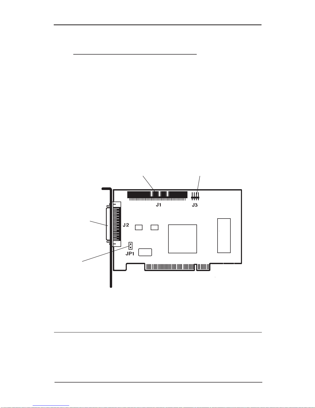
Figure 2-1. AP-10 SCSI PCI Board Layout
J2
External SCSI
High Density
50-Pin
Connector
J3
HDD Activity
LED
Connector
J1
Internal SCSI
50-Pin
Connector
2-2 Where to Next?
Your AP-10 SCSI PCI and its attached SCSI hard drives are
ready for use. Next, refer to Chapter 5: SCSI BIOS Setup to run
the SCSI BIOS Setup Utility, and Chapter 6: Software Installation
to install the appropriate drivers for your OS and devices.
Page 20

3-1
Introduction to SCSI
Chapter 3
Introduction to SCSI
3-1 Introducing the SCSI
SCSI, which is the acronym for Small Computer System Interface,
is a specification for a peripheral bus and command set. The
SCSI specification defines a high performance interface that
distributes data among peripherals independently of the host,
thereby freeing the host computer for more user-oriented
activities.
SCSI offers the advantage of letting you connect up to seven (15
on wide SCSI) internal and/or external SCSI devices to one
host adapter card. This enables you to use the other available
expansion slots for other add-on cards such as internal modem
or network cards.
Another SCSI advantage over other peripheral interfaces is that
SCSI is designed to keep computers in step with advancing
technologies. SCSI enables host computers to connect with
virtually any SCSI peripheral device without always having to
overhaul system hardware and/or software. The host computer
does not have to “learn” a new way to communicate every time
a peripheral device is added – the conflicting issues of interrupts
and COM/LPT port assignments are eliminated by the
independent scheme of assigning a unique SCSI ID number to
each device on the SCSI bus.
However, one important requirement (defined by the SCSI
specification) is the rule of device termination:
When adding SCSI devices, you must ensure that
the devices on both ends of the SCSI bus are
terminated and that all devices in-between are
NOT terminated.
Page 21

3-2
AP-10 SCSI PCI User's Manual
3-1.1 Basic SCSI Specifications
• A maximum of seven SCSI devices can be attached (daisy-
chained) to an 8-bit (referred to as narrow) SCSI bus. Up to
15 devices can be attached to a 16-bit (referred to as wide)
SCSI bus.
• Each SCSI device on the SCSI bus must have a different ID
assigned to it.
• The SCSI signals must be terminated at both ends of the
SCSI bus.
• When two SCSI devices communicate on the SCSI bus, one
acts as an initiator and the other acts as a target.
• Ultra SCSI specifications limit the total length of both
internal and external cables to up 3 meters (9.84 feet).
• It is strongly recommended that the same length of cabling
be used between external SCSI devices.
• Driver software must be installed to provide communication
between the SCSI bus and your computer.
The following table provides an overview of SCSI specifications:
Synch
Bus Conn- Transfer Max. # Cable
Width ectors Rate Devices* Length**
SCSI-1 8 bits 50 pins 5 MB/s 8 19.7 ft.
SCSI-2 8 bits 50 pins 5 MB/s 8 19.7 ft.
Fast SCSI-2 8 bits 50 pins 10 MB/s 8 9.8 ft.
Fast Wide SCSI-2 16 bits 68 pins 20 MB/s 16 9.8 ft.
Ultra SCSI 8 bits 50 pins 20 MB/s 8 9.8 ft.***
Ultra Wide SCSI 16 bits 68 pins 40 MB/s 16 9.8 ft.***
* Includes host adapter.
* * Maximum combined length of all cables.
* * * 4.9 feet if more than four devices are connected.
Page 22

3-3
Introduction to SCSI
3-2 SCSI ID
Your AP-10 SCSI PCI controller can support up to seven SCSI
peripherals in a daisy chain configuration. When connecting
multiple SCSI peripherals, each device must be assigned a
unique SCSI ID number on the SCSI bus. ID settings range from
“0” for the first device to “7” for the seventh SCSI device. The
AP-10 SCSI PCI controller itself is factory set as ID 7 on the
chain. This ID positions the controller in an ideal position for a
single controller environment on the SCSI bus. (Note: it can be
changed to any ID position on the bus.)
Your AP-10 SCSI PCI controller can be placed in any physical
position on the bus. The priority is determined by the device ID
and not the device's physical location on the bus.
Check each SCSI device you are planning to connect for its
factory set ID number. The device ID is typically set via jumpers
or switches on most SCSI peripherals.
The following defines the basic rules for SCSI ID numbers:
• The range for assigning SCSI devices is 0 to 7, with 7 having
the highest priority, 0 the lowest.
• Device priority on the SCSI bus is only used when multiple
devices are trying to access the bus simultaneously.
• SCSI ID 7 is normally reserved for the SCSI controller. Other
devices use SCSI ID numbers from 0 to 6 (when the controller
is at default ID 7).
• If you have two or more SCSI hard drives installed, the drive
with the lower ID will be your boot drive. SCSI ID 0 is best
reserved for the boot hard disk drive; SCSI ID 1 is best
reserved as the second hard disk drive.
Page 23

3-4
AP-10 SCSI PCI User's Manual
3-3 SCSI Termination
The SCSI bus must be properly terminated in order for its
connected devices to function correctly.
Only the devices installed on each end on the daisychained SCSI bus should be terminated; all other SCSI
devices should not be terminated.
Termination on internal mounted devices are generally
configured by “resistor terminators” or jumpers. Termination
on an external device usually requires simply plugging a
“terminator” into the open connector which would otherwise
receive the cable from the next device in the daisy chain. In some
cases, a switch may be used. Please refer to the manufacturer’s
documentation for any device you plan to add to your system
for its method of termination.
Internal Connections: one internal 50-pin connector is
provided for connecting narrow (8-bit) SCSI devices. The last
device on this bus should be terminated.
External Connections: one external high density 50-pin
connector is provided for connecting narrow (8-bit) SCSI
devices. The last device on this bus should be terminated.
AP-10 SCSI PCI Board: its Active Termination feature
automatically sets the proper termination of the board for you.
This guarantees proper termination of the board itself and
eliminates the need to remove the computer's cover if a change
is made in the SCSI bus configuration.
Figure 3-1 illustrates the correct terminations for the three
possible combinations of SCSI devices on the SCSI bus.
Page 24

3-5
Introduction to SCSI
1. Internal SCSI Devices Only with the SCSI Adapter
Internal
SCSI Device
(If Any)
SCSI Adapter
Termination
ON
Termination
OFF
Termination
ON
Internal
SCSI devices
(End)
SCSI Adapter
2. External SCSI Devices Only with the SCSI Adapter
Termination
OFF
Termination
ON
Termination
ON
External
SCSI Device
(If Any)
External
SCSI devices
(End)
Note that the termination on the SCSI Adapter will be OFF, if
both the internal and external devices are used.
Termination
OFF
SCSI Adapter
Termination
OFF
Termination
ON
3. Both Internal & External SCSI Devices with the
SCSI Adapter
Termination
OFF
Termination
ON
Internal
SCSI Device
(End)
Internal
SCSI devices
(If Any)
External
SCSI Device
(End)
External
SCSI devices
(If Any)
Figure 3-1. SCSI Bus Termination Configurations
Page 25

3-6
AP-10 SCSI PCI User's Manual
3-4 SCSI Cables
When connecting peripheral SCSI devices to your system,
it is important that you always use high quality cables.
For external devices use: double shielded twisted pair cable.
For internal devices use: unshielded flat ribbon cable.
DO NOT BUY CHEAP CABLES.
• External device cables should be constructed of high quality
double-shielded twisted pair cable.
Mid-quality external cables may be okay for slower SCSI-1
or SCSI-2 devices. However, Fast SCSI-2 and particularly
Ultra SCSI devices are extremely sensitive to cable quality
and will not perform reliably if high quality cabling is not
used.
• Use the shortest cable possible. Do not use cables shorter
than 30 cm (11.8 inches) between any two external SCSI
devices.
Cable length also impacts performance because signals
weaken with longer distance of travel and are susceptible to
noise.
• Use the same length of cable between each external
SCSI device.
• The Ultra SCSI specification limits the total length of
all cables to up to 3 meters (9.84 feet) or 4.9 feet if more than
four devices are connected.
Page 26

4-1
Hardware Installation
This chapter provides an in-depth description of the steps
required to install your AP-10 SCSI PCI board. It includes
instructions on how to:
• install your SCSI board in your computer
• install SCSI peripheral devices
The installation of the AP-10 SCSI PCI board is plug-and-play
compatible and its configuration will be automatically set for
you.
After completing the hardware setup in this chapter, refer to
Chapter 5: SCSI BIOS Setup to run the BIOS Setup Utility and
Chapter 6: Software Installation to install the appropriate drivers
for your operating system and devices.
4-1 Installing Your AP-10 SCSI PCI
WARNING: STATIC ELECTRICITY DISCHARGE
may permanently damage your system. In order to avoid
possible static electricity discharge during installation
procedures, please follow the guidelines below:
• Discharge any static electricity build up in your body
by touching a large grounded metal surface such as the
computer case, if plugged in.
• During installation procedures, avoid any contact
with internal parts. Handle cards only by their edges.
WARNING: Disconnect the AC power source before
removing the cover.
Chapter 4
Hardware Inst allation
Page 27

4-2
AP-10 SCSI PCI User's Manual
Proceed with the following instructions to install the AP-10
SCSI PCI in your computer. General instructions for installing
the board are given since the design of computer cases varies.
Refer to your computer’s reference manual whenever in doubt.
1. Make a backup copy of the Driver Installation Diskettes that
are included with the board.
2. Turn OFF the power to your computer and any other
connected peripheral devices.
3. Unplug all power cords and cables from the back of the
computer. (Be sure to note the cable connections for
reconnection when the installation is complete.)
4. Remove your computer’s cover by removing its mounting
screws with a screwdriver. Slide the cover OFF.
5. Remove the board from its anti-static wrap.
6. Option for Multiple Initiators only: Jumper JP1 is
provided to support certain conditions where the SCSI
bus is configured to have more than one SCSI host
adapter installed in at least two different computer
systems sharing peripheral devices. For multiple
initiators on a single SCSI bus, jumper JP1 can be used to
set the termination ON all the time. This will ensure
proper termination in case one computer is off. The AP-
10 SCSI PCI is shipped without the jumper installed
and need not be changed in most cases.
Page 28
4-3
Hardware Installation
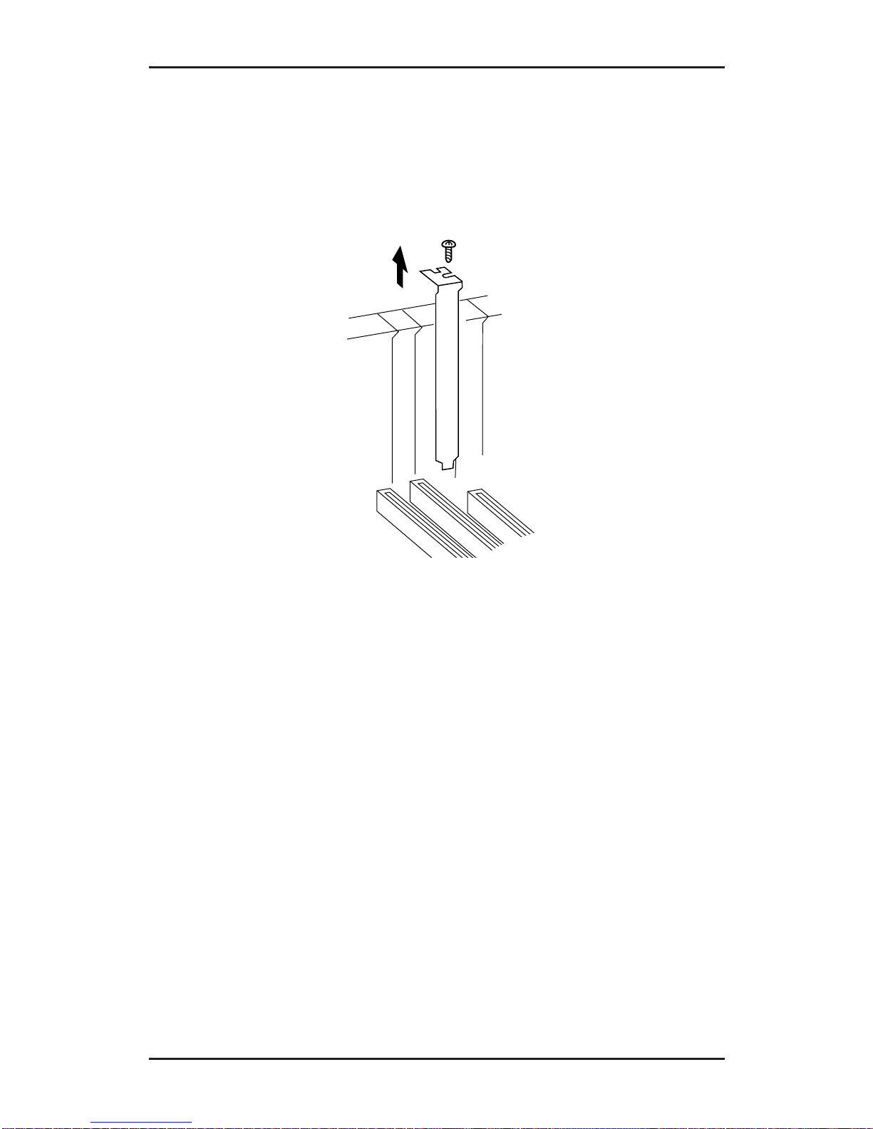
7. Select an available PCI-bus slot and remove the slot cover by
unscrewing the holding screw and sliding it out. Save this
screw for securing the board after it’s installed.
Figure 4-1. Remove the Slot Cover
Page 29

4-4
AP-10 SCSI PCI User's Manual
Figure 4-2. Installing the AP-10 SCSI PCI Board
8. To install the board, carefully align the board’s bus
connector with the selected PCI-bus expansion slot on the
motherboard. Push the board down firmly, but gently,
until it is well seated.
NOTE: Hold the board by its external edges only. Try to
avoid touching the components, connectors or pins.
9. Replace the slot cover’s holding screw to secure the board
to the rear slot panel.
Your AP-10 SCSI PCI board is now installed.
Page 30

4-5
Hardware Installation
4-2 Connecting the SCSI Devices
You can connect up to seven internal and/or external SCSI
devices to your system via the external and internal ports on
your AP-10 SCSI PCI board.
NOTES
• Do not connect differential devices; use only
single-ended devices.
• It is important that you always use high-quality
double shielded twisted-pair external cable.
In order to run 10 MBytes/sec data transfer rate,
SCSI specifications limit the total combined
length of all cables to up to 3 meters (9.84 feet)
(4.9 feet for more than four devices).
Figure 4-3. AP-10 SCSI PCI Board Layout
J2
External
SCSI
High-density
50-pin
Connector
J3
HDD Activity
LED
Connector
J1
Internal SCSI
50-Pin
SCSI Connector
JP1
Multiple
Initiator
Jumper
Page 31

4-6
AP-10 SCSI PCI User's Manual
4-2.1 Internal SCSI Devices Only
1. Your AP-10 SCSI PCI provides one internal 50-pin connector.
2. Configure and install each internal SCSI device, such as
hard disk or CD-ROM drives in your computer according
to the manufacturer’s instructions.
a. Follow the rules for terminating devices on the SCSI bus
(see Chapter 3). Remember: only the devices at each end
of the SCSI bus must be terminated. Refer to the
manufacturer’s documentation for proper termination
of the devices you plan to install.
b. Verify that the factory default SCSI ID number set on
each device you plan to install is valid. If there is a
conflict, reset it to an available ID (0-6 assuming board
default of ID 7) following the manufacturer’s
instructions.
3. Use the internal 50-pin 3-position SCSI ribbon cable that
was included with the board for attaching 8-bit SCSI
devices. (If you plan to connect more than two devices, see your
local dealer for a ribbon cable that supports multiple devices.)
a. Plug the last connector on the ribbon cable into
the connector on the internal SCSI device
following the appropriate device manufacturer's
instructions. Make sure “pin 1” on the cable’s
connector, indicated by the colored edge-stripe)
is matched with the device connector’s pin 1.
Make sure the connector is well seated.
b. To connect a second internal SCSI device, plug the
middle connector on the ribbon cable into the
connector on the second internal SCSI device.
Again be aware of matching pin 1s. Make sure the
connector is well seated.
c. Plug the connector at the other end of the ribbon
Page 32

4-7
Hardware Installation
cable into the 50-pin connector J1. Make sure the
connector is well seated. Note that the connector is
keyed to ensure proper pin 1 alignment.
4. Most computers have a disk drive activity indicator light
Figure 4-4. Connecting the Internal 50-pin SCSI Cable
Colored
Edge-stripe
Pin 1
End of SCSI Bus
Termination
AUTOMATICALLY
ENABLED
Termination
OFF
Termination
OFF
End of SCSI Bus
Termination ON
Figure 4-5. Connecting Internal SCSI Devices
Page 33

4-8
AP-10 SCSI PCI User's Manual
(LED) on its front panel. You can plug in the cable from this
LED, to the J3 connector on your AP-10 SCSI PCI. The LED
will light when there is SCSI bus activity. (Refer to your
computer’s manual regarding this LED cable.)
For systems with a two-position LED cable, plug its 2-pin
connector to pins 1 and 2 of connector J3.
Note: If you make this connection, the LED will no longer
indicate non-SCSI activity, such as for an IDE drive if
installed.
5. After completing all your internal connections, double
check that the devices are installed properly (including
terminations), and the cable connections are secure.
6. Replace the cover and reconnect all power cords and cables
to the back of the computer.
If you plan to attach external peripheral device(s) at this time,
make sure the termination on all devices is correct. (Refer to
Chapter 3, page 3-4.) Then, continue with the next section to make
your external connection(s) to the AP-10 SCSI PCI's J2 port.
Page 34

4-9
Hardware Installation
4-2.2 External SCSI Devices Only
NOTE
Your AP-10 SCSI PCI is shipped with one internal
ribbon cable You will need an additional doubleshielded twisted-pair cable for each external
peripheral device you wish to connect — which
should be daisy-chained off the external J2
connector on the board.
1. Configure each SCSI device, such as a scanner or
CD-ROM drive according to the manufacturer’s
instructions.
a. Follow the rules for terminating SCSI devices. (See
Chapter 3, page 3-4.)
b. Verify that the default SCSI ID number set on each
device is valid. If there is a conflict, reset it to an available
ID (0-6 assuming board default of ID 7) following the
manufacturer’s instructions.
2. Attach the high density 50-pin SCSI cable connector end to
the external connector on the AP-10 SCSI PCI and the other
end to your SCSI device.
If you are connecting more than one device, connect the
cables between the SCSI devices in a daisy-chained
configuration.
3. Connect the power cords to the peripherals and refer to
their manuals for operation.
Page 35

4-10
AP-10 SCSI PCI User's Manual
J1
ABP940
Host Adapter
Card
J2
End of SCSI Bus
TERMINATION
AUTOMATICALLY
ENABLED
End of SCSI Bu s
TERMINATION
ENABLED
NO
TERMINATION
NO
TERMINATION
Maximum 7 SCSI
Periperal Devices
Installable With One
ABP940
Device
#1
Device
#2
External SCSI
Devices
Device
#7
Termination
OFF
Termination
OFF
End of SCSI Bus
Termination ON
End of SCSI Bus
Termination
AUTOMATICALLY
ENABLED
Figure 4-6. Connecting External Devices
4-2.3 Internal & External SCSI Devices
The following illustrates the configuration for attaching both
internal and external SCSI devices to your AP-10 SCSI PCI.
J2
J1
End of SCSI Bus
TERMINATION
ENABLED
End of SCSI Bus
TERMINATION
ENABLED
NO
TERMINATION
NO
TERMINATION
Maximum 7 SCSI
Periperal Devices
Installable With One
ABP940
ABP940 Host Adapter Card
TERMINATION
AUTOMA T I CALLY
DISABLED
Device
#7
Device
#1
End of SCSI Bus
Termination ON
Internal SCSI
Devices
Termination
OFF
Termination
OFF
End of SCSI Bus
Termination ON
External SCSI
Devices
SCSI Adapter
Termination
AUTOMATICALLY
DISABLED
Figure 4-7. Connecting Internal & External Devices
Page 36

4-11
Hardware Installation
4-3 Host Computer Configuration
Most computer manufactures with a PCI bus automatically
configures the add-on card's I/O port address, IRQ Channel
and BIOS address. If this is not the case with your computer
system, you will need to enter the system Setup program and
manually change the PCI setting.
There are two methods of configuring the PCI bus from the host
computing system:
1. Setting jumpers on the host system motherboard.
2. Setting CMOS incorporated into the host system.
In either case, you will need to refer to the host computer system
documentation to complete PCI bus activation and setup.
Depending on your system configuration, refer to the following
to configure the system’s CMOS setup:
1. If an IDE drive and a SCSI drive are both present in the
system: the IDE drive will be your boot drive (Drive C)
and its drive type must be defined in CMOS Setup; the
drive type of the SCSI drive (Drive D) must be set to
“Not Installed”.
2. In a SCSI only system, CMOS setup must be run and both
"Drive C" and "Drive D" must be defined as “Not
Installed”.
After updating the CMOS Setup, save the changes to rewrite
the CMOS configuration. Then, reboot your system.
Page 37

4-12
AP-10 SCSI PCI User's Manual
4-4 Where to Next?
At this point, your AP-10 SCSI PCI and its attached SCSI hard
disk drives are ready for use. Proceed with the following:
• Run the SCSI BIOS setup utility by pressing <Ctrl><I>
keys when prompted during system bootup. Refer to
Chapter 5: SCSI BIOS Setup for instructions on how to use
this convenient program to configure the SCSI bus.
• Install the appropriate drivers for your operating system
and peripheral devices. Refer to Chapter 6: Software
Installation for instructions on how to install the software
drivers.
Note that Windows 95 supports most SCSI devices. (Certain
device drivers may also be independently supplied by the
device’s manufacturer.)
If your PC already has an operating system (OS) installed: go
to Chapter 6, Software Installation and follow the applicable
instructions to install the appropriate software files for your
operating system.
If an operating system is not yet installed: proceed first with
its installation. The SCSI BIOS has built-in hard disk drive
support, so you should experience normal operation with any
attached SCSI hard drive. Then, install the appropriate software
files for your OS. Refer to Chapter 6, Software Installation for
instructions.
To maximize the use of multi-tasking operating systems, such
as Novell, UNIX, Windows NT or OS/2, some of the default
settings of the SCSI BIOS configuration may be changed. Your
AP-10 SCSI PCI includes its own SCSI BIOS Setup utility for
configuring the SCSI Bus. Refer to Chapter 5, SCSI BIOS Setup
for instructions on how to use this menu-driven setup program
to manually configure its feature options.
Page 38

5-1
SCSI BIOS Setup
Chapter 5
SCSI BIOS Setup
This chapter will guide you through the use of the on-board
SCSI BIOS Setup Utility. This utility simplifies the SCSI
installation process by eliminating the need for opening the
system to change system jumpers and switch settings. All
necessary AP-10 SCSI PCI functions for customizing your
system are accessible through this utility.
5-1 Power up Introduction
After verifying your hardware installation and running the
System CMOS Setup (as described in Chapter 4, page (4-11),
your newly installed AP-10 SCSI PCI controlled SCSI bus is
now ready for setup. First turn your external SCSI peripherals
ON (if present); then, power ON your computer system. The
system monitor should display the following information, but
may vary, based on the system BIOS manufacturer:
• The normal POST and memory test procedure.
• The AP-10 SCSI PCI’s sign on message including a list of
detected SCSI devices.
The list should match the peripheral devices attached to the
bus. In most cases, the host computer system is now configured
and ready for use.
Some situations will require that a low-level format be
performed using the controller’s BIOS Setup Utility to initialize
a SCSI disk drive and lay the foundation for a bootable SCSI
drive.
Page 39

5-2
AP-10 SCSI PCI User's Manual
5-2 Using the SCSI BIOS Setup Utility
The on-board menu-driven SCSI BIOS Setup Utility is provided
as a convenient means for configuring the AP-10 SCSI PCI
board and certain SCSI bus device parameters without having
to open the computer. It also includes a low-level format and
diagnostics utilities for disk drives.
5-2.1 Running SCSI BIOS Setup
To run the SCSI BIOS Setup Utility, turn on or reboot your
computer after verifying the drive setup defined by the system
BIOS Setup. (Refer to the end of Chapter 3.) During the boot
routine, press <Ctrl><I> at the same time when the banner
prompt is displayed.
!!! Press <Ctrl><I> for SmartSCSI Setup Utility !!!
When you enter the SCSI BIOS Setup Utility, you will be
presented with the following main menu option screen:
SIIG SC2459 SCSI Setup Utility Ver 1.06
PCI Bus:00 Device:0AH Port:E400H IRQ:12
Scan Bus Device Setup Adapter Setup BIOS Setup Disk Utility
ESC:Exit : Select : Execute F2: Toggle Color/Monochrome
Use the following keys to navigate through the menu options:
• Use the arrow keys to move the cursor.
• Use the numeric keypad < + > key to toggle a selection.
• Press the <Enter> key to execute/select.
• Press the <Esc> key to exit/return to previous menu.
• Press <F8> to load default values.
Page 40

5-3
SCSI BIOS Setup
The next sections will describe how to use the various
menu-option screens as you progress through the program.
Scan Bus Option
This option scans the SCSI bus. All device ID’s are displayed on
the screen: recognized devices on the SCSI bus and SCSI ID’s
without devices attached. This allows for better definition of
location and priority on the SCSI bus.
• A device ID should only be changed if it conflicts with
another device address on the same bus.
• The best ID for a bootable hard disk is SCSI ID 0.
SIIG SC2459 SCSI Setup Utility Ver 1.06
PCI Bus:00 Device:0AH Port:E400H IRQ:12
Scan Bus Device Setup Adapter Setup BIOS Setup Disk Utility
Press any key to exit
ID 0 : no device
ID 1 : no device
ID 2 : no device
ID 3 : no device
ID 4 : no device
ID 5 : no device
ID 6 : no device
ID 7 : SIIG SC2459 H/A
ESC:Exit : Select : Execute
Page 41

5-4
AP-10 SCSI PCI User's Manual
Device Setup Option
Selecting this option presents an on-screen table of available
options that can be individually set for each SCSI device.
SIIG SC2459 SCSI Setup Utility Ver 1.06
PCI Bus:00 Device:0AH Port:E400H IRQ:12
Scan Bus Device Setup Adapter Setup BIOS Setup Disk Utility
SCSI Device ID #0 #1 #2 #3 #4 #5 #6 #7
Asynchronous Transfer No No N o No No No No N o
Max. Synchronous Transfer 10.0 10.0 10.0 10.0 10.0 10.0 10.0 10.0
DOS Space > 1GB Yes Yes Yes Yes Yes Yes Yes Yes
Spin Up Disk Drive No N o No N o No N o No N o
Enable Disconnect Yes Yes Yes Yes Yes Yes Yes Yes
ESC:Exit : Select +:Change Value F8:Load Defaults
SCSI ID: Displays all of the SCSI device ID #s.
Asynchronous Transfer: Sets whether the AP-10 SCSI PCI will
negotiate for asynchronous transfers. A device is always
checked first for synchronous transfer; then asynchronous. If
you know a device is only asynchronous, then selecting “yes”
will save time by not checking for synchronous transfers.
Yes: Select this if you know the device does not support
synchronous transfers—only asynchronous transfers.
No: Select this if you know the device supports synchronous
transfers. (Default setting.)
Max. Synchronous Transfer: Your AP-10 SCSI PCI supports data
transfer speeds to and from the SCSI bus up to 10 MBytes/sec.
Each device can be set for its specific synchronous data transfer
rate. You can choose from a range between 5 and 20 MB/sec.
This feature will save the time that would otherwise be needed
to negotiate the speed before initiating transfers. The following
identifies standard settings.
5: Set for synchronous SCSI-2 devices.
10: Set for synchronous Fast SCSI devices. (Default setting)
20: Set for synchronous Ultra SCSI devices.
Page 42

5-5
SCSI BIOS Setup
DOS Space > 1GB: Set this option to enable the Extended BIOS
translation which allows your computer to access a DOS SCSI
hard disk capacity greater than 1 gigabyte— up to 8 gigabytes.
Yes: Select this for SCSI hard disks greater than 1 gigabyte. It
extends the upper limit from 1 GByte to 8 GBytes by
increasing the translation scheme to 255 heads and 63
sectors per track. This is a powerful option. DATA CAN
BE LOST BY CHANGING SETTINGS. (Default setting.)
No: Select this for SCSI hard disks less than or equal to 1
gigabyte where DOS limits the number of cylinders per
drive to 1024. The host adapter uses a translation scheme
of 64 heads and 32 sectors per track.
Spin Up Disk Drive: Some drives have a built-in power saving
mode. When this type of drive is not being accessed, it will slow
down or turn off.
Yes: Select to support drives with power-saving feature.
No: Select if device is not a power-saving feature drive.
(Default setting.)
Enable Disconnect: The host adapter uses this option to allow a
device to temporarily disconnect/reconnect from the SCSI
bus. This allows the host adapter to perform other functions on
the bus while the device is temporarily disconnected. The
device and the host adapter can then reconnect when the bus
is needed. (Default setting = Yes.)
CAUTION
It is highly recommended that the default
setting for this option be used, unless your
drive is incapable of supporting disconnects.
Page 43

5-6
AP-10 SCSI PCI User's Manual
Adapter Setup Options
Selecting this option presents an on-screen listing of options
that can be set for the AP-10 SCSI PCI “Host Adapter”.
SIIG SC2459 SCSI Setup Utility Ver 1.06
PCI Bus:00 Device:0AH Port:E400H IRQ:12
Scan Bus Device Setup Adapter Setup BIOS Setup Disk Utility
Host Adapter SCSI ID 7
Boot Device ID 0
SCSI Terminator Automatic
SCSI Parity Check ON Yes
ESC:Exit : Select +:Change Value F8:Load Defaults
Host Adapter SCSI ID: This option allows you to change the SCSI
ID# of the AP-10 SCSI PCI board from the default value
of 7. The AP-10 SCSI PCI provides seven IDs, numbered
0-7, with 7 having the highest priority. (Default setting = 7.)
More than one host adapter is permitted on the same PCI bus.
This will allow the system to have more than one SCSI bus
attached. Under these conditions the SCSI device ID’s can be
repeated.
Boot Device ID: This option is used to set which SCSI device will
be the designated boot device for the system. This host adapter
supports seven SCSI IDs to boot from. (Default setting = 0.)
SCSI Terminator: This option is used to set the board’s termination.
Automatic = Automatically detects and sets the proper
termination for you (Default setting)
ON = Terminated
OFF = Not terminated
Page 44

5-7
SCSI BIOS Setup
SCSI Parity Check ON: Enables or disables SCSI parity checking
when reading from the SCSI bus to verify correct transmission
of data from the SCSI devices
Yes: This is the recommended setting as a security check to
verify data. (Default setting.)
No: Disables parity check. Although most current SCSI
devices do support SCSI parity, this option should be
disabled on devices which do not support SCSI parity.
BIOS Setup Options
Selecting this option presents an on-screen listing of options
that can be set for the on-board SCSI BIOS.
SIIG SC2459 SCSI Setup Utility Ver 1.06
PCI Bus:00 Device:0AH Port:E400H IRQ:12
Scan Bus Device Setup Adapter Setup BIOS Setup Disk Utility
7
Enable Host Adapter BIOS Yes
BIOS Support For More Than 2 Drives Yes
BIOS Treat Removable Disks as Fixed Disk N o
ESC:Exit : Select +:Change Value F8:Load Defaults
Enable Host Adapter BIOS: This option controls the host adapter’s
BIOS usage of SCSI disk I/O routines. Disabling this option
will eliminate the host adapter’s ability to utilize its boot
capabilities and will disable all subsequent options displayed
in this menu. Enabling the AP-10 SCSI PCI board’s BIOS allows
you to take advantage of the SCSI bus control features. This
BIOS can manage SCSI hard disk drives without additional
drivers.
Yes: Select if you have a hard disk drive. Controls usage of
SCSI disk I/O routines within the SCSI BIOS.
(Default setting.)
No: Disables disk boot capabilities. Select if you are only
running CD-ROM, tape backup, etc. with own device
drivers —saves memory resources. If two SCSI controller
cards exist, select “No” on one of the controller cards.
Page 45

5-8
AP-10 SCSI PCI User's Manual
BIOS Support For More Than 2 Drives :
With MS-DOS 5.0 or later,
enables the SCSI BIOS to control more than two hard disk
drives without having to install special drivers. It allows the
DOS fdisk program to partition up to eight disk drives,
eliminating the need for aspidisk. If it is not needed, disable this
feature to save memory resources.
Yes: If you have two or more hard disk drives and have DOS
5.0 or later. (Default setting.)
No: If you have an earlier version than DOS 5.0 or do not
have more that two hard disk drives.
The optimum ID for multiple drive operation is device ID0 for
a system disk and device ID1 for the second drive.
(Default setting.)
BIOS Treat Removable Disks as Fixed Disk: Allows the BIOS to
control removable-media drives, such as iomega, Bernoulli
and SyQuest drives, as if they were hard disk drives, without
installing additional software drivers. To have the ability to
interchange media during operation, additional third party
drivers will be needed for that peripheral device.
This feature can be used for system security. Removable disks
configured as boot disks can be used to lock your system when
they are removed. To do this, make sure no other boot drive is
in your system. Then, format a removable cartridge and partition
it to be a boot device. Insert this cartridge before powering up,
and remove it after powering down.
Yes: The BIOS supports all removable-media drives like a
hard disk, including as a boot drive.
No: Removable-media drives are not treated as hard disks.
In this mode, software drivers are needed because the
drives are not controlled by the BIOS. (Default setting.)
NOTE
DO NOT remove media controlled by the SCSI BIOS
while the system is powered on. Data will be lost! The
BIOS does not support removability while the system
is turned on. If you want to remove media while the
system is powered, you must install additional third
party device drivers.
Page 46

5-9
SCSI BIOS Setup
Disk Utility
The SCSI Disk Utility can be used to verify media and low-level
format disk devices. When you enter the SCSI Disk Utility, it
scans the SCSI bus and lists all SCSI devices installed on the bus.
Highlight select the desired SCSI disk device by using the
cursor keys and press <Enter>.
SIIG SC2459 SCSI Setup Utility Ver 1.06
PCI Bus:00 Device:0AH Port:E400H IRQ:12
Scan Bus Device Setup Adapter Setup BIOS Setup Disk Utility
Select the Disk and Press <Enter>
ID 0 : no device
ID 1 : no device
ID 2 : no device
ID 3 : no device
ID 4 : no device
ID 5 : no device
ID 6 : no device
ID 7 : SIIG SC2459 H/A
ESC:Exit : Select : Execute
Page 47

5-10
AP-10 SCSI PCI User's Manual
SIIG SC2459 SCSI Setup Utility Ver 1.06
PCI Bus:00 Device:0AH Port:E400H IRQ:12
Scan Bus Device Setup Adapter Setup BIOS Setup Disk Utility
ID 0 : no device
ID 1 : no device
ID 2 : no device
ID 3 : no device
ID 4 : no device
ID 5 : no device
ID 6 : no device
ID 7 : SIIG SC2459 H/A
ESC:Exit : Select : Execute
Highlight select the desired disk operation by using the cursor
keys and press <Enter>.
Verify Disk: This utility scans the selected device’s media for
defects. If it finds bad blocks, you will be prompted to reassign
them If “yes” is selected, the bad blocks will no longer be used.
Verification can be aborted at any time by pressing <Esc>.
Format Disk: This utility is used to low-level format SCSI disk
devices, which is a procedure that must be performed before
you can use your operating system’s partitioning and file
preparation commands, such as MS-DOS fdisk and format.
Please note that most SCSI disk devices are shipped preformatted and
do not need reformatting. However, in cases where a drive has
been used with other host adapters, the drive should have a
low-level format performed. This sets the media to a state
which is easily recognized by the host adapter on the SCSI bus.
WARNING: All data will be lost when performing
a low-level format. Make sure you back up all data
before proceeding with this operation. The format
process cannot be aborted once it is in progress.
Verify Disk
Format Disk
Page 48

6-1
Software Installation
Chapter 6
Software Installation
The following sections describe the procedures for installing drivers
to enable your AP-10 SCSI PCI to operate properly under specific
operating system environments.
6-1 MS-DOS/Windows 3.1 Driver Installation
Your AP-10 SCSI PCI’s on-board BIOS provides the necessary
functions to support most operations. When using MS-DOS
v5.0 or later, the BIOS will support up to seven hard disks;
for DOS 4.01 or below, only two drives are supported.
The BIOS supports most hard disk functions without
additional device drivers. However, you will need to install
a device driver provided by the device’s manufacturer to
support other types of SCSI devices, such as CD-ROM, tape
backup, scanner, etc.
IMPORTANT
It is important that the SCSI bus hardware and
operating system are installed correctly before
proceeding further.
6-1.1 For an Existing MS-DOS System
Perform the following steps to install the ASPI driver for the
MS-DOS operating system:
1. Turn on your computer to boot to the DOS prompt.
2. Insert the AP-10 SCSI PCI Driver Installation Disk 1 into the
floppy drive.
Page 49

6-2
AP-10 SCSI PCI User's Manual
3. At the a:> or b:> prompt, type: dossetup and press <Enter>.
4. Follow the on screen instructions.
5. Select “Reboot Now” to reboot the system to load the ASPI
driver. Remove the diskette to complete bootup.
If a CD-ROM, tape drive, scanner, or optical drive is installed
on your system, a device driver may be needed. A driver
may be provided by the manufacturer to provide proper
support for that particular device. Please refer to your
peripheral device manufacturer documentation for more
information.
6-1.2 For an Existing Windows 3.1x System
Perform the following steps to install the ASPI driver for
Windows 3.1x operating system. It is important the SCSI
adapter and Windows 3.1x operating system are installed
correctly before proceeding.
NOTE
If you already installed the ASPI driver for
MS-DOS, you do not need to reinstall the driver.
1. Turn on your computer to boot into DOS. Type win to run
Windows 3.1x.
2. Insert the AP-10 SCSI PCI Driver Installation Disk 1 into the
floppy drive.
3. Select “Run…” from the Windows Program Manager.
Execute the following steps:
• Type a:\setup <Enter>. A series of screens will guide
you through the installation.
• Choose “Continue” to install the driver on your hard disk.
• Choose “Continue” to accept the Host Adapter
selection.
Page 50

6-3
Software Installation
4. Two installation options are available:
• Express Install: to install both the DOS ASPI drivers
and the Windows 32-bit Disk Access drivers. Use this
option if you are unfamiliar with configuring DOS or
Windows manually.
• Custom Install: to select DOS ASPI drivers or the
Windows 32-bit Disk Access drivers manually. Use this
option only if you are familiar with configuring DOS
or Windows manually.
5. Follow the on-screen directions and/or options to continue
the installation.
• Choose “Continue” to accept the default directory or enter
the full directory where you want ASPI drivers installed.
• Choose “Continue” after all the files have been copied and
installed to your system.
• Continue as prompted to define the MSCDEX.EXE path.
Choose “Continue” to copy the files.
• Select “Yes” to make the required changes to your
system’s CONFIG.SYS and SYSTEM.INI configuration
files.
• Once the “SETUP was successful” screen is displayed,
choose “Continue”.
6. To complete the installation and activate the driver, exit
from your Windows 3.1x session and reboot the system
by pressing <Ctrl><Alt><Del>.
Page 51

6-4
AP-10 SCSI PCI User's Manual
6-1.3 Driver Command Line Options
The driver supports command line switches to optimize
driver operation. From inside the CONFIG.SYS file for MSDOS, use the following format when modifying the driver
switches:
The standard format for command line switches is:
Device=c:\siigaspi\siigaspi.sys [Driver Config Option]
[Driver Config Options]:
/D Verbose Mode provides detail information about
driver on system command line when driver is
initialized.
/L Driver scan eight LUNs for each SCSI target.
/Bb,dd Scan device only on PCI Bus # b & Device # dd.
[The range for “b” is from 0 to 7. The range for “dd”
is from 0 to 20.]
/Bb Scan all devices on the PCI Bus # b. [The range for “b”
is from 0 to 7.]
/Sdd Scan device only on the PCI Bus #0 & Device # dd.
[The range for “dd” is from 0 to 20.]
/CCBSx Defines the maximum number of concurrent I/O
that the driver supports [The range for “x” is from
1 to 16.]
Page 52

6-5
Software Installation
6-2 Windows 95 Driver Installation
The AP-10 SCSI PCI supports Microsoft Windows 95 with the
addition of an ASPI driver. Once installed, the driver will be
automatically initialized during the system boot routine.
Choose one of the following procedures to install the driver:
• Adding the Windows 95 driver to an existing Windows 95
system
• Updating the SIGSCSI.mpd driver
6-2.1 For an Existing Windows 95 System
Windows 95 will automatically detect the presence of new
hardware in Plug-and-Play compliant systems. It is important
that the AP-10 SCSI PCI has been properly installed before
proceeding further.
1. Microsoft Windows 95 will detect the presence of new
hardware upon boot-up and will display a dialog window
titled New Hardware Found and PCI SCSI Bus Controller will
be identified.
• From the options presented, select:
“• Driver from disk provided by hardware manufacturer”,
then “OK”.
• Select “SCSI Controller” from the list of available devices,
then select “Have Disk...”
2. In the Install from Disk window, enter the AP-10 SCSI PCI
Driver path name:
• Insert AP-10 SCSI PCI Driver Installation Disk 1 into drive
A:
• Type: a:\win95, select “OK.”
3. Select “Yes” to finish and restart your computer. The system
will reboot to Windows 95.
Page 53

6-6
AP-10 SCSI PCI User's Manual
4. It is highly recommended that you verify the Windows 95
driver has been properly installed.
• Select “My Computer” from the Main Desktop.
• Select “Control Panel” from the My Computer group.
• Select “System” from the Control Panel group.
• Select the “Device Manager” tab from the System group.
• Select “SCSI Controllers” from within the Device Manager
listing, then “SCSI350P/SCSI360P/SC2459 SCSI Host
Adapter”. If “This device is working properly” is displayed,
the driver has been correctly installed.
6-2.2 Updating the Driver
1. Once a Windows 95 session is established, perform the
following steps:
• Select “My Computer” from the Main Desktop.
• Select “Control Panel” from the My Computer group.
• Select “System” from the Control Panel group.
• Select the “Device Manager” tab from the System group.
• Select “SCSI Controllers” from within the Device Manager
listing.
• Select “SCSI350P/SCSI360P/SC2459 SCSI Host Adapter”
from the SCSI Controllers listing.
• In the SCSI350P/SCSI360P/SC2459 SCSI Host Adapter
“Properties” window, select the “Driver” tab, then select
“Change Driver”.
• In the “Select Device” window, select “Have Disk...”.
• In the Install from Disk window, enter the SIIG SCSI
driver path name:
- Insert AP-10 SCSI PCI Driver Installation Disk 1 into
- drive A.
- Type: a:\win95, select “OK”.
• Select “Yes” to finish and restart the computer.
Page 54

6-7
Software Installation
2. It is highly recommended you verify that your Windows
95 driver has been properly installed.
• Select “My Computer” from the Main Desktop.
• Select “Control Panel” from the My Computer group.
• Select “System” from the Control Panel group.
• Select the “Device Manager” tab from the System
group.
• Select “SCSI Controllers” from within the Device
Manager listing, then “SCSI350P/SCSI360P/SC2459 SCSI
Host Adapter”. If “This device is working properly” is
displayed, the driver has been correctly installed.
Page 55

6-8
AP-10 SCSI PCI User's Manual
6-3 Windows NT Driver Installation
The AP-10 SCSI PCI supports Windows NT v3.5x/4.0 with the
addition of a driver. After you install the driver, it will be
automatically loaded during each system boot.
Choose one of the following procedures to install the driver:
• New Windows NT system installation
• Adding the Windows NT device driver to an existing
Windows NT system
6-3.1 New Windows NT System Installation
The AP-10 SCSI PCI board must be installed before installing
Windows NT.
1. Begin by installing Windows NT according to the Windows
NT user’s manual.
2. Follow the instructions on the screen until you come to a
window titled: Windows NT Workstation Setup.
• Press <Enter> to continue setting up Windows NT.
• Press the “S” key to skip mass storage detection.
• Press the “S” key to configure additional SCSI adapters.
3. When prompted, scroll down the list and select “Other
(Requires Disk Provided by a Hardware Manufacturer)”
from the list of Additional SCSI Adapters. A message will
appear on screen stating to:
• Remove the Windows NT diskette in drive A.
• Insert the AP-10 SCSI PCI Driver Installation Disk 1 and
press <Enter>.
• Select “SIIG SCSI350P/SCSI360P/SC2459 PCI SCSI
Host Adapter”. Press <Enter>.
Page 56

6-9
Software Installation
4. The AP-10 SCSI PCI Windows NT driver is now installed.
Continue with the on-screen instructions to complete the
installation of Windows NT. Refer to your Windows NT
user’s manual for completion of the operating system
installation procedure.
6.3.2 For an Existing Windows NT System
These instructions will guide you through the installation of the
AP-10 SCSI PCI Windows NT driver for computer systems that
boot from an IDE drive or other SCSI host adapter.
CAUTION
If you have not already done so, backup all files
before proceeding. Consult your operating system
documentation for proper system backup
procedures.
1. Once a Windows NT session is established, perform the
following steps:
• Select “My Computer” from the Main Desktop.
• Select “Control Panel” from the My Computer group.
• Select “SCSI Adapters” from the Control Panel group.
2. Select the “Drivers” tab from the SCSI Adapters group.
• In the Drivers window, select “Add…”
3. In the Install Driver window, select “Have Disk...”.
4. In the Install from Disk window, enter the SIIG SCSI driver
path name:
• Insert the AP-10 SCSI PCI Driver Installation Disk 1 into
drive A:
• Type: A:\WINNT, select “OK”.
5. Select “SIIG SCSI350P/SCSI360P/SC2459 PCI SCSI Host
Adapter”, then select “OK” to install the driver onto your
hard disk.
Page 57

6-10
AP-10 SCSI PCI User's Manual
6. In the Windows NT Setup window, enter the SIIG SCSI path
name to continue:
• Type: A:\WINNT, then select “Continue.”
This completes the AP-10 SCSI PCI Windows NT driver
installation. Follow the on-screen directions. Click “Yes” to
restart you computer and activate the new driver.
7. It is highly recommended you verify that your Windows NT
device driver has been properly installed.
• Select “My Computer” from the Main Desktop.
• Select “Control Panel” from the My Computer group.
• Select “SCSI Adapters” from the Control Panel group.
• Highlight “SIIG SCSI350P/SCSI360P/SC2459 PCI SCSI
Host Adapter” from the SCSI Adapters listing and select
“Properties”. If “This device is working properly” is
displayed, the driver has been correctly installed.
Page 58

6-11
Software Installation
6.4 Novell NetWare Driver Installation
The AP-10 SCSI PCI NetWare driver supports Novell NetWare
386 v4.XX or v3.1X. The installation procedure described here
requires some experience in Novell system setup and
administration.
6-4.1 New NetWare 4.xx Installation
In most cases you will load the drivers during a new installation
of NetWare from CD-ROM. The AP-10 SCSI PCI NetWare
driver is loaded during the NetWare Server Installation
procedure. The NetWare installation program will prompt you
for the required parameters as the installation procedure
progresses. It is highly recommended that you have a copy of
the Novell NetWare Installation and Upgrade Manual for
reference.
1. At the MS-DOS prompt for CD-ROM installation, change
directories to where the installation files are located, e.g.,
d:\netware4.0\english\.
2. Type install <Enter> to initialize the installation routine.
3. Select Install new NetWare v4.x and press <Enter>.
4. Follow the instructions in the NetWare User’s Manual for
partitioning the hard drives and naming the system.
5. Follow the directions on screen until you come to a
window titled: Load Disk Driver.
• Press the <Ins> key to insert a new device driver.
• Press the <F3> key to specify a different source drive/
directory.
6. In the new window that is displayed enter the AP-10 SCSI
PCI device driver path name:
• Insert AP-10 SCSI PCI Driver Installation Disk 1 into
drive A:
• Type: A:\netware\v4x. Press <Enter>
Page 59

6-12
AP-10 SCSI PCI User's Manual
7. In the window “Select a New Disk Driver to Install:” a list of
available AP-10 SCSI PCI drivers for NetWare and their
version numbers will be displayed.
• Select “sigscsi.dsk”, press <Enter>.
• System will ask for confirmation to load new driver, press
<Enter>.
• Press <Enter> to continue.
8. Once you have selected the driver, the Loaded Drivers
window below the list of Available Drivers will be updated
with the driver name you have selected. Press <Enter> to
continue the installation.
9. This completes the device driver installation. Follow the
on-screen directions to complete the Novell NetWare
installation.
6-4.2 For an Existing NetWare System
The following procedures describe the installation for NetWare
version 4.11:
1. To begin the installation you will need to change the directory
to the location of the server and initialize the network server.
• Type cd \ nwserver <Enter>
• Type server <Enter>
2. At the NetWare prompt, Type load install <Enter>.
3. From the Driver Options window, select “Configure disk
and storage device drivers”. Press <Enter>.
4. From the Additional Drive Actions window select:
“Select an additional driver”. Press <Enter>.
5. From the Select a driver: screen, press the <Ins> key to install
an unlisted driver.
6. Press <F3> to specify a different path. Type in
a:\netware\v4x and press <Enter>.
Page 60

6-13
Software Installation
7. The following driver should be displayed in the window:
SIGSCSI.DSK SIIG SCSI350P/SCSI360P/SC2459 Ultra
SCSI PRO SCSI Modules
Press <Enter>.
8. Select “Yes” to copy the driver SIGSCSI.DSK.
9. Press <Enter>.
10. Specify a Server boot path. Type: c:\nwserver
Press <Enter>. The driver files will be copied.
11. Select “No” to the message “Do you want to select an
additional disk driver?” Press <Enter>.
12. Press <Esc> and continue to “exit INSTALL”.
6-4.3 Driver Command Line Options
The AP-10 SCSI PCI drivers support command line switches to
optimize driver performance. However, in certain situations
some driver optimization may be advantageous to system
performance.
NetWare offers two means of entering command line switches.
One method is for session usage and needs to be entered each
time the system is rebooted.
:Load (Pathname) sigscsi [Driver Config Option]
The second method listed is for permanent installation. In
startup.ncf you can include the following statement:
Load (Pathname) sigscsi [Driver Config Option]
Driver Config Options:
/V Verbose Mode provides detail information about driver
on system command line when driver is initialized.
/!V Non Verbose Mode (default).
/L Driver assumes that all targets have more than one LUN.
/!L Driver assumes that all targets only have LUN 0 (default).
Page 61

6-14
AP-10 SCSI PCI User's Manual
/T:xxxx
Target enable mask WORD (Default scan all targets).
/B:b,dd Scan device only on PCI BUS #b, PCI DEVICE #dd.
/B:b Scan all the devices on PCI BUS #b (from 0 to 7).
/Q:q Specifies maximum number of tag commands per target
(default 4).
/!Q No tag.
/WR Read after write, hardware verify.
/!WR Not verified (default).
/R Support removable media (default).
/!R Will not support removable media.
/D Enable support for fixed disk drive (default).
/!D Disable support for fixed disk drive.
Page 62

6-15
Software Installation
6-5 OS/2 Driver Installation
The AP-10 SCSI PCI OS/2 driver supports OS/2, 3.0 & 4.0.
Choose one of the following procedures to install the driver:
• New OS/2 system installation.
• Adding the OS/2 driver to an existing OS/2 system.
6-5.1 New OS/2 System Installation
These instructions will guide you through the AP-10 SCSI PCI
OS/2 driver and OS/2 installation at the same time. OS/2 can
be installed from floppy diskettes or from CD-ROM.
1. Make a duplicate copy of OS/2 Diskette 1 using a blank
diskette and label it as “OS/2 Diskette 1 for AP-10 SCSI
PCI”.
2. Copy the sigscsi.add file from the AP-10 SCSI PCI Driver
Installation Disk 1 (OS/2 subdirectory) to the root directory
on the “OS/2 diskette 1 for AP-10 SCSI PCI”.
3. Using an appropriate text editor modify the CONFIG.SYS
on the OS/2 Diskette 1 for AP-10 SCSI PCI to include the
new sigscsi.add driver.
• Enter: basedev=sigscsi.add and save the file.
4. Insert the OS/2 Installation Diskette into drive A: and turn
on your computer. This will begin the OS/2 installation and
establish an OS/2 bootable hard drive.
5. When prompted, insert the “OS/2 Diskette 1 for AP-10 SCSI
PCI.” Follow the on-screen instructions to continue.
6. You have completed the device driver installation for OS/
2. Follow the on-screen instructions and OS/2 manual for a
complete description of OS/2 installation.
Page 63

6-16
AP-10 SCSI PCI User's Manual
6-5.2 For an Existing OS/2 System
These instructions will guide you through the installation of the
AP-10 SCSI PCI OS/2 driver for computer systems that boot
from an IDE drive or other SCSI host adapter.
1. Once an OS/2 session is established, insert the AP-10 SCSI
PCI Driver Installation Disk 1 into your floppy drive.
2. Select “Device Driver Install” from the System Setup group.
3. Select “Change” source directory to the root directory of the
floppy disk.
4. Select “OS2” and select “Set”.
5. Select “Destination Directory”.
6. Select “Change” destination directory to any existing
OS/2 directory or accept the default.
7. Select “Set”.
8. From the Device Driver Installation Group select “Install”.
9. Select the “SIIG SCSI350P/SCSI360P/SC2459 Ultra SCSI
Pro Device Driver for OS/2”. Select “OK”.
10. Select “Exit” to install the OS/2 device driver. Exit and
reboot the system to activate the device driver.
6-5.3 Driver Command Line Options
The AP-10 SCSI PCI OS/2 drivers support command line
switches to optimize driver performance. Device drivers
normally require no further information to work effectively.
However, in certain situations some driver optimization may be
advantageous to system performance. From inside the
CONFIG.SYS file use the following format to edit the file:
Page 64

6-17
Software Installation
The standard format for command line switches is:
basedev = sigscsi.add [Driver Config Option]
Driver Config Options:
/V Verbose Mode provides detail information about
driver on system command line when driver is
initialized.
/!V Non Verbose Mode (default).
/ET Driver assumes that all targets have more than one
LUN.
/!ET Driver assumes that all targets only have LUN 0
(default).
/T:hhhh Target enable mask WORD (Default scan all targets)
in hex format.
/B:b,dd Scan device only on PCI BUS #b, DEVICE #dd (in
decimal format).
/B:b Scan all the devices on PCI BUS #b (from 0 to 7).
/A:n Assigns adapter number based on BIOS address.
/DM:t,t,t Enable direct access storage device (DASD) support.
/!DM:t,t,t Disable DASD manager support.
/SM:t,t,t Enable SCSI manager support.
/!SM:t,t,t Disable SCSI manager support.
/Q:q Specifies maximum number of tag commands per
target.
/!Q No tag.
Page 65

6-18
AP-10 SCSI PCI User's Manual
6-6 SCO UNIX Driver Installation
The AP-10 SCSI PCI SCO UNIX driver supports SCO UNIX
System V/386 Release 3.2 v4.0 or later, SCO Open Desktop
v2.0, v3.0 or later, and SCO Open Server Release 3.0 & 5.0.x.
6.6-1 Updating Interrupts and Hardware Settings
The following interrupt configuration settings are suggested
as the most effective means of providing a controller interrupt
to the host adapter:
• The AP-10 SCSI PCI supports interrupt levels: 9, 11, 15,
(IRQ 11 is recommended)
• Avoid using interrupt 10 as the controller interrupt
• Set first SCSI disk ID to 0 (first time install requirement)
• Set tape target ID to 2. (If tape is in use)
• Set CD-ROM target ID to 5. (If CD-ROM is in use)
Refer to your system documentation to set the interrupt levels
and your peripheral documentation for help setting SCSI IDs.
6.6-2 New SCO UNIX System Installation
1. Insert the SCO UNIX N1 boot disk into the floppy drive and
turn on the system. At the SCO UNIX boot prompt, type:
link then press < Enter >.
2. The system will ask you what packages you want linked to
the system; type: i91u then press < Enter >.
The system at this point will boot into SCO UNIX. When
prompted by the installation, insert the AP-10 SCSI PCI
Driver Disk 2 into your floppy drive. Press < Enter >.
3. You have completed the installation of the SCO UNIX
driver. Follow the on-screen instructions to continue the
installation until you see “insert i9IU package BTLD
disk...”. Insert the AP-10 SCSI PCI Driver Disk 2. Select “OK”,
then follow the on-screen instructions to complete.
Page 66

6-19
Software Installation
6-6.3 For an Existing SCO UNIX System
1. Insert the AP-10 SCSI PCI Driver Installation Disk 2 diskette
into your floppy drive.
2. Type: installpkg under the command prompt, press <Enter>.
3. The system will ask you what packages you wish to install.
Type: i91u , then press < Enter>
4. Change the directory and type the following to rebuild the
UNIX kernel:
cd /etc/conf/cf.d < Enter>
./link_unix < Enter>
5. You have completed the link procedure for the driver. Exit
and reboot the system.
6-6.4 Setting as the Bootable Host Adapter
1. Insert the AP-10 SCSI PCI Driver Installation Disk 2 into the
floppy drive.
2. Type: installpkg under command prompt and press
<Enter>. The system will ask you what packages you want
to install. Type: i91u <Enter>.
3. Type the following to change the mscsi file:
cd /etc/conf/cf.d < Enter >
cp mscsi mscsi.bak < Enter>
vi mscsi < Enter>
ha attach number ID lun
i91u Stp 0 2 0
i91u Sdsk 0 0 0
i91u Srom 0 5 0
4. Rebuild the UNIX kernel:
. /link_unix < Enter>
5. You have completed the link procedure for the driver.
Exit and reboot the system.
Page 67

6-20
AP-10 SCSI PCI User's Manual
6-7 SCO UnixWare Driver Installation
The AP-10 SCSI PCI supports UnixWare 2.x.
Interrupt Request Setting:
The AP-10 SCSI PCI’s interrupt level must be set to IRQ 10 for
proper installation of its driver. Please refer to your system
documentation to set the interrupt levels and your peripheral
documentation for help in setting SCSI IDs.
6-7.1 New UnixWare System Installation
In most cases you will load the drivers during a new installation
of UnixWare from CD-ROM. The driver is loaded during the
early stages of the installation procedure. The UnixWare
installation program will prompt you for the required parameters
as the installation procedure progresses. It is highly
recommended that you have a copy of the SCO UnixWare
Installation Handbook and SCO UnixWare System Owner
Handbook for reference.
1. Insert the “SCO UnixWare Installation Diskette” into the
floppy drive and turn on the computer. Follow the onscreen installation instructions.
2. When prompted to “Install host bus adapter drivers”, insert
the AP-10 SCSI PCI Driver Installation Disk 2 into drive A:
press <Enter>.
3. When prompted to “Install another HBA diskette”, press
<Enter> to continue.
4. Follow the on-screen instructions.
• Remove the AP-10 SCSI PCI Driver Installation Disk 2.
Select “Continue Installation” and press <Enter>.
• Then, select “Continue Installation” again and press
<Enter>.
5. This completes loading the device driver. Follow the onscreen directions to complete the SCO UnixWare installation.
Page 68

6-21
Software Installation
6-7.2 For an Existing UnixWare System
1. Once a UnixWare session is established and a command
prompt is ready, type (recall that UnixWare is case sensitive):
cp /stand/unix /stand/unix.org <Enter>
pkgadd -d diskette1 <Enter>
2. Select “i910u ihv hba” from the list of available host drivers,
press <Enter>.
3. If the AP-10 SCSI PCI is intended to be the bootable host
adapter, the next step to updating the driver will require a
revision to the i910u file. These instructions will guide you
through changing the current software settings for
UnixWare to establish the AP-10 SCSI PCI as the host
adapter for your boot device:
• At the system command prompt, type
cd /etc/conf/sdevice.d
• Use “vi” or another editor to modify the file i910u by
adding a line
- Locate the line $version2
- Edit the file by adding the line $static immediately
following $version2.
• Rebuild the UnixWare kernel by typing the following
steps at the command prompt :
/etc/conf/bin/idbuild -B <Enter>
cp /etc/conf/cf.d/unix /stand/unix <Enter>
cd / <Enter>
shutdown -g0 ( 0 is Zero ) <Enter>
Y <Enter>
4. If the AP-10 SCSI PCI is NOT intended to be the bootable
host adapter, these instructions will guide you through
changing the current software settings for UnixWare to
establish the AP-10 SCSI PCI as a non-bootable host adapter
for your device:
Page 69

6-22
AP-10 SCSI PCI User's Manual
At the system command prompt, type:
/etc/conf/bin/idbuild -M i910u <Enter>
cd / <Enter>
shutdown -g0 ( 0 is Zero ) <Enter>
Y <Enter>
5. Exit the UnixWare program and reboot your system to
initialize the new device driver to control the AP-10 SCSI
PCI.
6-7.3 Using Multiple Host Adapters
UnixWare is capable of supporting up to eight SCSI busses. If
you choose to use multiple host adapters in your system, verify
that each host adapter shared interrupt level is set to IRQ10.
Please refer to your system documentation to set the interrupt
levels.
Space for each AP-10 SCSI PCI host adapter in the system is
configured and allocated by a separate line in the file:
/etc/conf/sdevice.d/i910u.
Verify that “Y” is selected in the second field at the line starting
at i910u in the file /etc/conf/sdevice.d/i910u for each AP-10
SCSI PCI in the system.
UnixWare will automatically rebuild the kernel when an
additional AP-10 SCSI PCI is detected.
Page 70

6-23
Software Installation
6-7.4 Removing the Driver
1. Once a UnixWare session is established and a command
prompt is ready, type (recall that UnixWare is case sensitive):
/etc/conf/bin/idinstall -d i910u <Enter>
to delete the following files:
/etc/conf/mdevice.d/i910u
/etc/conf/sdevice.d/i910u
/etc/conf/pack.d/i910u/driver.o
/etc/conf/pack.d/i910u/space.c
/etc/conf/pack.d/i910u/disk.cfg
2. Then rebuild the UnixWare kernel by executing the following
commands at the system prompt:
/etc/conf/bin/idbuild -B -K <Enter>
/cp /etc/conf/cf.d/unix /stand/unix <Enter>
cd/ <Enter>
shutdown -g0 (where 0 is Zero) <Enter>
Y <Enter>
Page 71

6-24
AP-10 SCSI PCI User's Manual
Page 72

7-1
Troubleshooting
Chapter 7
Troubleshooting
The following section provides commonly asked questions and answers
to problems encountered during the installation of the AP-10 SCSI
PCI. It also includes information specific to DOS Space >1GB issues.
7-1 Questions & Answers
Q: Why isn’t the banner “!!! Press <CRTL><I> for SmartSCSI
Setup Utility !!!” displayed when I power up the system?
A: Verify that all cabling to the AP-10 SCSI PCI is installed
correctly. Refer to hardware installation section of this manual.
Q: On boot-up the message “SCSI BIOS Installed” is
displayed, but my system hangs.
A: Verify that the CMOS interrupt structure is set to INTA
and the CMOS IRQ level matches the jumper settings on the
motherboard. Refer to your PC user manual.
Q: On boot-up, not all the peripherals are scanned and
recognized.
A: Verify that each of the SCSI devices on the bus has its own
distinct SCSI ID number and all peripherals are receiving
power. Refer to your peripheral manual for information
regarding changing SCSI ID’s.
Verify the SCSI Termination is set correctly. Make sure the last
peripheral on the SCSI bus has termination. See the peripheral
manual for proper termination information.
Page 73

7-2
AP-10 SCSI PCI User's Manual
If the attached peripherals are still not recognized after
checking the previous steps, configure the AP-10 SCSI PCI to
operate in an Asynchronous Transfer mode by changing its
setting through the Device Setup section of the SCSI BIOS Setup
Utility. Refer to Chapter 5: SCSI BIOS Setup Utility.
Q: On boot-up, I get a message “Missing Operating System”,
displayed. The boot drive is greater than 1 gigabyte.
A: Verify the “DOS SPACE> 1 GB” is enabled in the SCSI
BIOS Setup Utility.
Q: Under SCO UnixWare, the system displays a panic
message or crashes during bootup.
A: Reboot the system and verify that the AP-10 SCSI PCI is
using IRQ10. Refer to your system documentation to set the
interrupt levels and your peripheral documentation for help in
setting SCSI ID’s.
In order to boot from the old UnixWare kernel, reboot the
system and execute the following steps:
• Begin an interactive boot session by pressing the
<Spacebar> at the BOOTING UNIXWARE prompt.
• At the system [boot]# prompt, type KERNEL=unix.org
<Enter>
• Type go <Enter>.
Consult the SCO UnixWare Installation Handbook
“Troubleshooting” section to help isolate the problem. If it
becomes necessary to remove the SCSI device driver, please
consult the “Removing the SCSI Driver from the SCO UnixWare
System” section of this document.
Page 74

7-3
Troubleshooting
7-2 DOS Space > 1GB
The default disk head mapping for the AP-10 SCSI PCI is 64
heads and 32 sectors. Under this configuration, the MS-DOS
limit is 1024 cylinders per drive. This translates to a maximum
accessible capacity of 1 GB per drive. By changing the head
mapping to 255 heads and 63 sectors, the “DOS Space > 1GB”
option can support disk capacities up to 8 gigabytes under MSDOS.
WARNING: If you have already installed the operating
system on your hard drives, changing the head mapping will
corrupt your files and cause other unexpected problems.
Before changing any “DOS Space > 1GB” option setting,
please back up your disk drives. Then you should run the
FDISK utility to delete all the partitions on your selected disk
drive. At this point you can switch the setting, reinstall the
operating system, and restore your backed up files.
All device drivers for the AP-40 SCSI PCI will support different
head mappings based on the setting of “DOS Space > 1GB”
option.
7-2.1 MS-DOS, OS/2 & Windows NT
Under MS-DOS, OS/2 & Windows NT, we recommend you
enable the “DOS Space > 1GB” option if your SCSI hard disk
has more than 1 GB capacity.
7-2.2 NetWare 386
NetWare does not have a 1GB barrier. Therefore, the “DOS
Space > 1GB” option is not required to be enabled; however,
you must verify the boot partition is located below 1024 cylinders.
If the size of your boot partition is greater than 1 GB or the
location of the boot partition is beyond 1 GB, you should enable
the “DOS Space > 1GB” option.
Page 75

7-4
AP-10 SCSI PCI User's Manual
7-2.3 SCO UNIX
SCO UNIX does not have a 1 GB barrier. Therefore, the “DOS
Space > 1GB” option is not required to be enabled; however,
you must make sure the root file system is located below 1024
cylinders in order to perform the kernel boot routines. If the size
of the root file system is greater than 1 GB or the location of root
file system is beyond 1 GB, you should enable the “DOS Space
> 1GB” option.
SCO UNIX cannot support different head mappings for each
disk drive under the same host adapter. The head mapping will
be based on the setting represented by target ID 0.
7-2.4 Drives with Multiple Operating Systems
It is mandatory that the same head mapping be used across
multiple operating systems on one drive. However you can use
different head mappings on different drives with the exception
of SCO UNIX. It is recommended that you enable “DOS Space
> 1GB” option if the capacity of your SCSI hard disk has more
than 1 GB.
 Loading...