

Page 1
User's Guide
Solvent Ink
Color Inkjet Printer
IP-6900
Seiko I Infotech Inc.
Read this User's Guide to use the printer safely and
properly. Keep this manual in a place where you
can quickly access it at any time.
U00094405401
Page 2

IP-6900 Solvent Ink Color Inkjet Printer User's Guide
Documents Number U00094405401
First Edition, May 2005
Second Edition, June 2005
Copyright © 2005 by Seiko I Infotech Inc.
All rights reserved
Seiko I Infotech Inc. reserves the right to make changes without notice to the specifications and
materials contained herein and shall not be responsible for any damages (including consequential) caused by reliance on the materials presented, including but not limited to typographical,
arithmetic, or listing errors.
Please address any questions, comments, or suggestions to:
Seiko I Infotech Inc.
8, Nakase 1-chome, Mihama-ku, Chiba-shi.
Chiba 261-8507, Japan
This manual acknowledges the following trademarks:
SII is a trademark of Seiko Instruments Inc.
All other trademarks are the property of their respective companies.
This equipment has been tested and found to comply with the limits for a Class A digital device,
pursuant to Part 15 of the FCC Rules. These limits are designed to provide reasonable protection
against harmful interference when the equipment is operated in a commercial environment.
This equipment generates, uses, and can radiate radio frequency energy and, if not installed and
used in accordance with the instruction manual, may cause harmful interference to radio
communications. Operation of this equipment in a residential area is likely to cause harmful
interference, in which case the user will be required to correct the interference at his own expense.
Durch die Kennzeichnung dieses Produktes mit dem CE-Zeichen erklärt Seiko den folgenden
Direktiven der Europäischen Union zu entsprechen (mit Wirkung vom siehe Datum):
Januar 1996:- EG-Direktive 73/23/EEC ergänzt durch EG-Direktive 93/68/EEC, Angleichung der
Gesetze der einzelnen Mitgliedsstaaten bezüglich Geräten mit niedriger Betriebsspannung.
Januar 1996:- EG-Direktive 89/336/EEC, Angleichung der Gesetze der einzelnen Mitgliedsstaaten
bezüglich elektromagnetischer Kompatibilität.
Den vollständigen Text dieser Erklärung einschließlich der Definition der entsprechenden
Direktiven sowie der jeweiligen Standards erhalten Sie von Ihrem Seiko Colorgrafx Systems
Kundendienst oder Ihrem Seiko Engineering Systems Kundendienst.
Page 3

Thank you very much for purchasing the IP-6900 Color Inkjet
Printer (simply called the printer below).
This printer is a color inkjet printer that uses solvent ink, supports
104 inch media width, and has a built-in SCSI interface.
This manual, the IP-6900 User's Guide, describes the features of
the printer, names of components, information needed before use,
and basic operations, such as how to turn the power ON and OFF
and set media and ink.
The following items should be read before reading Section 1:
- Contents of package
- Safety precautions
- Handling precautions
- Notation
Read these items to use the printer safely and properly. Keep this
manual in a place where you can quickly access it at any time.
Introduction
Page 4

Page 5
i
Contents of Package
The printer components, including options, are installed on the main
unit on delivery. Make sure that the items listed on this page and
the next page are present.
If any parts are missing or damaged, contact the shop where you
purchased the product or the nearest service center.
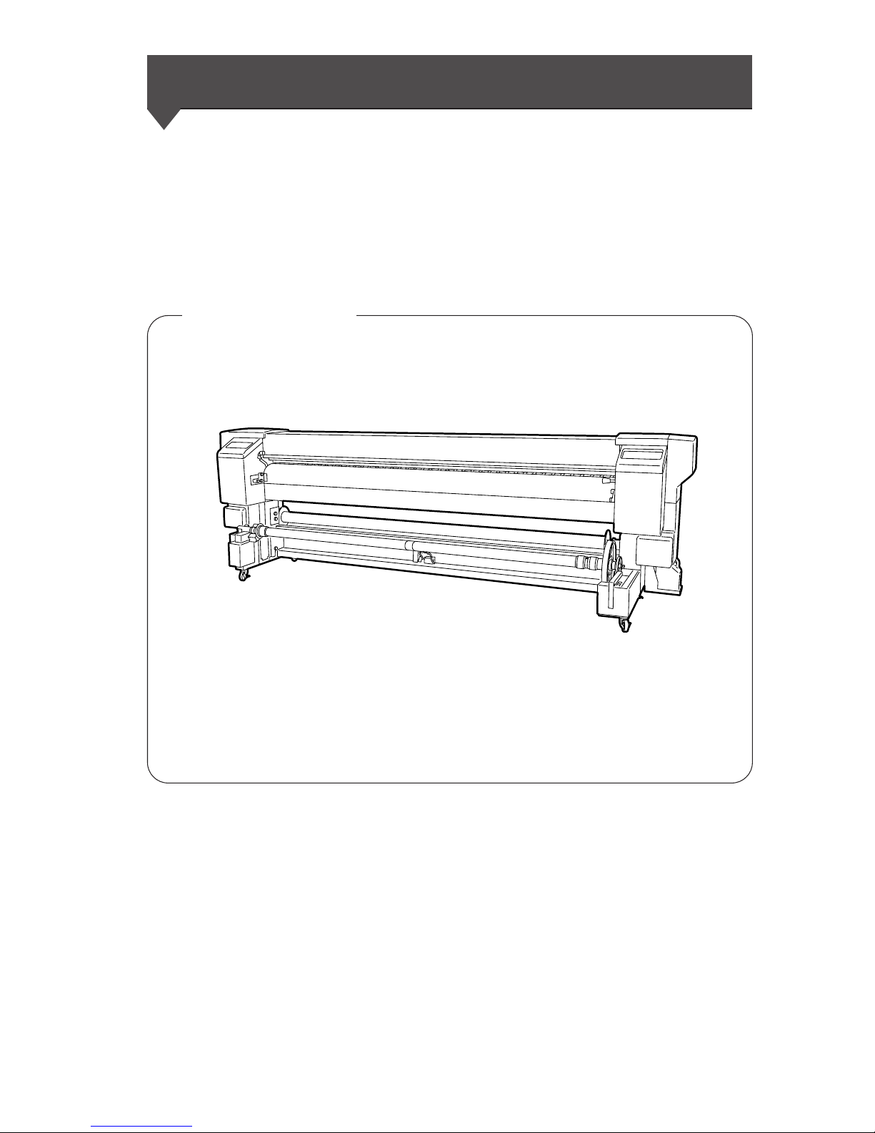
Printer main unit <1>
• Built-in SCSI interface.
• Main unit includes the paper feeder and take-up unit
Basic components
Page 6
ii
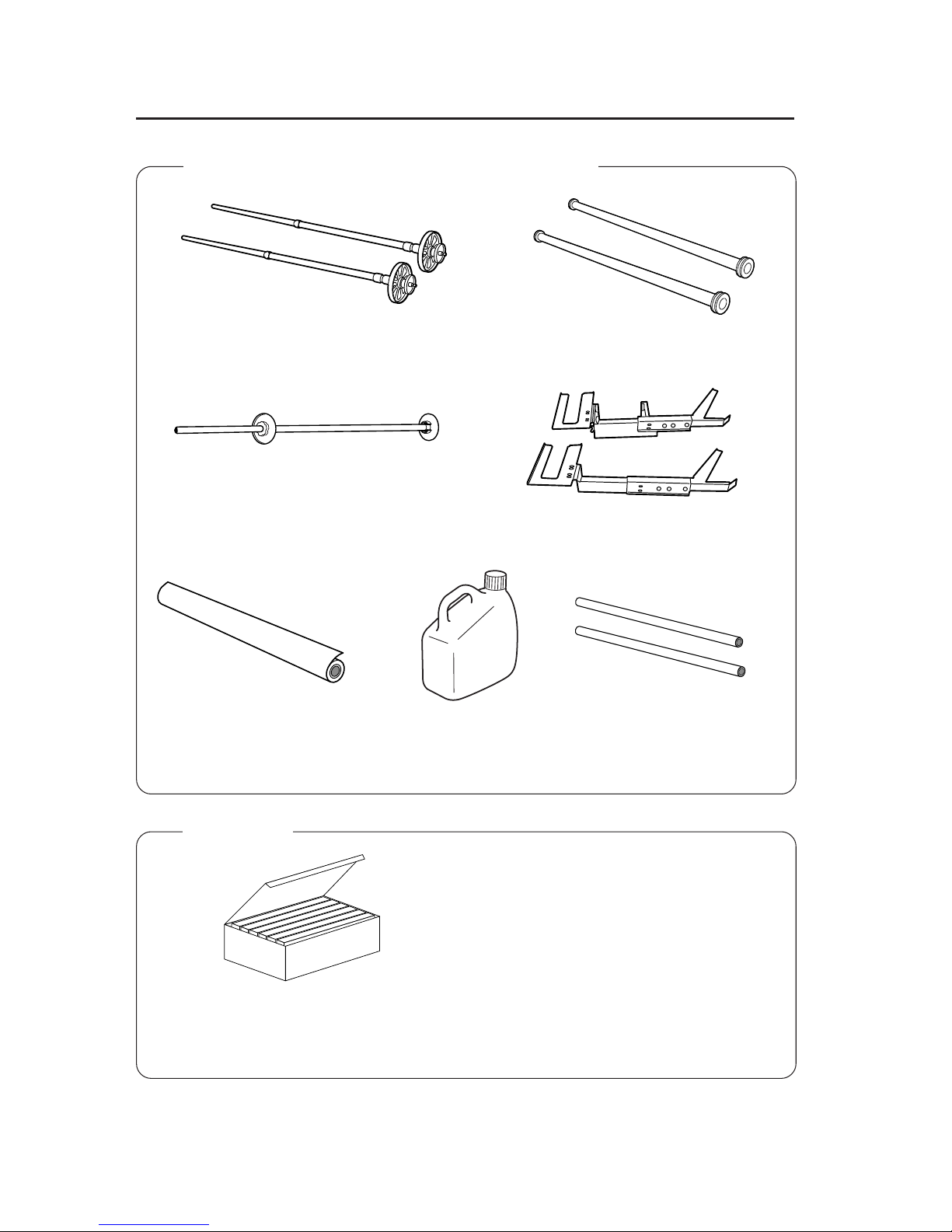
*: The ink capacity of each ink cartridge for starter kit 6 colors IP6-160 is 1000ml.
Part of the ink in the starter kit is consumed for initial ink charge and installation check, so that the full
amount of ink cannot be used for printing.
Media for adjustment
<1>
Starter kit 6 colors IP6-160
(Y, M, C, Bk, Lc, Lm)
<1>
Waste ink bottle IP6-109
<1>
Paper tube 104"
(For take-up unit)
<2>
Main scroller
<2>
Sub scroller
<1>
Tension bar
<2>
Tension bar guide
<1>
Accessories packed together with main unit
Options
Page 7
iii
• Dryer 100 (IP-270) : 1
• Exhaust Attachment 100 : 1
• PS RIP (PhotoPrint 4 DX) : 1
• PS RIP (PhotoPrint 4 Server) : 1
• Footswitch : 1
• SCSI cable (9 m) : 1
Maintenance kit IP6-108
<1 set>
• Cap cleaning liquid: 100 ml
• Wiper cleaning liquid: 100 ml
• Cleaning swab: 50 pieces
• Syringe: 10 pieces
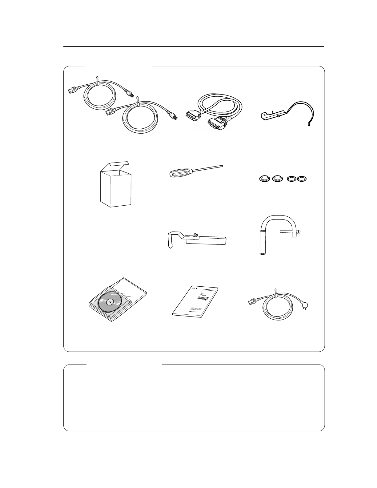
Phillips head screw driver
(for head up/down adjustment)
Media positioning tool
<1>
Update CD
<1>
Dryer power cable
<1>
Tension bar holder
<5>
Scroller grip
<1>
Power cable
<2>
SCSI cable
<1>
User's Guide
<1 copy, this manual>
• Main scroller : 1
• Sub scroller : 1
• Tension bar : 1
• Peeling bar : 1
• Dual roll set : 1
• Edge guide (for special printing) : 2
Optional accessories
Accessories box
* : Optional accessories can be ordered separately.
Flanges and fixing rings
(2 each) for tension bar
Page 8
iv
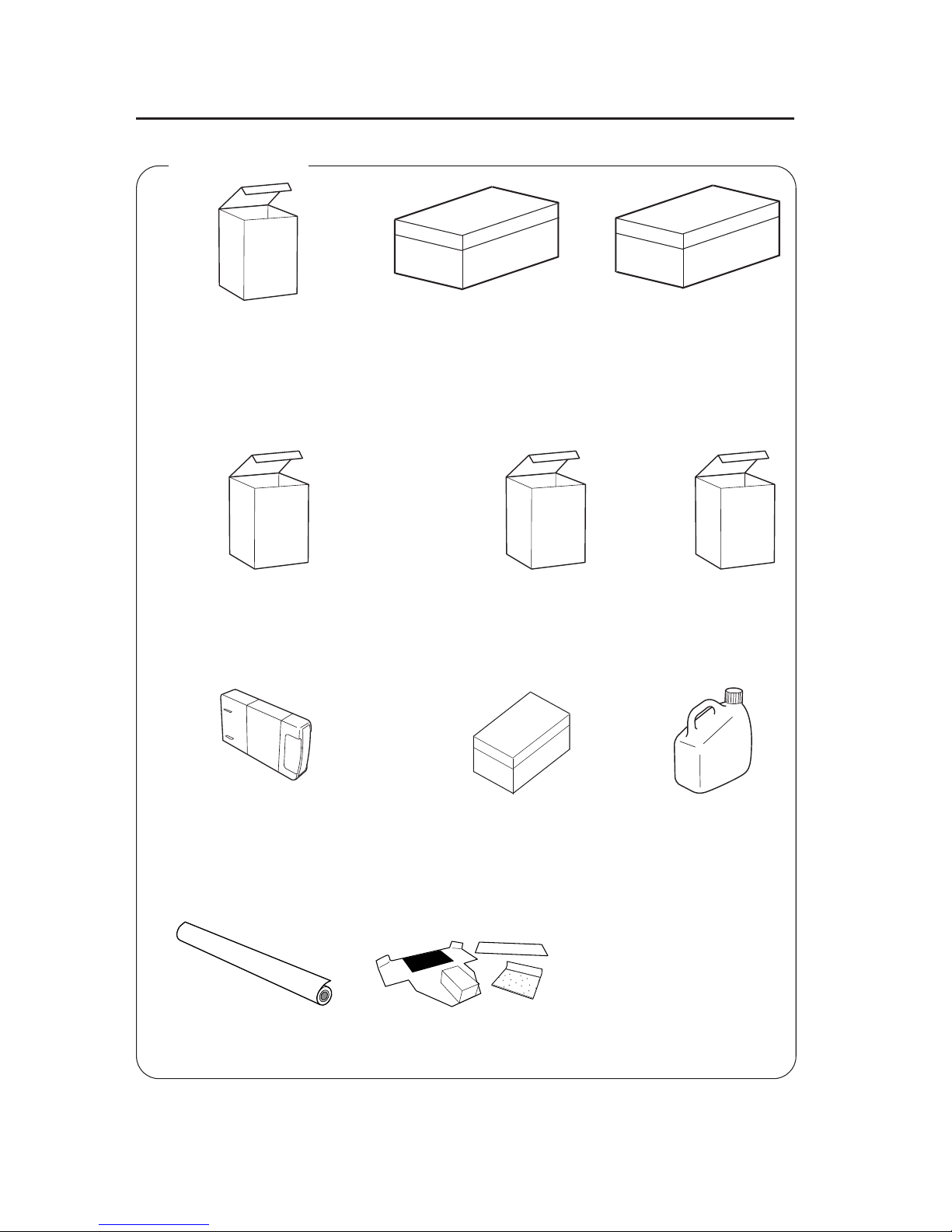
Consumables
* : Consumables can be ordered separately.
Maintenance Kit IP6-108
<1 set>
• Cap cleaning liquid: 100 ml
• Wiper cleaning liquid: 100 ml
• Cleaning swab: 50 pieces
• Syringe: 10 pieces
Storage Kit IP6-137
<1 set>
• Maintenance liquid cartridge: 6
• Dummy cartridge: 6
Cleaning Kit IP6-117
<1 set>
• Cleaning liquid cartridge: 6
• Dummy cartridge: 6
Cap cleaning liquid: 6 bottles
IP6-138 < 1 set >
Cap cleaning liquid (100ml) : 6 bottles
Wiper cleaning liquid: 6 bottles
IP6-139 < 1 set >
Cleaning swab
IP6-147
<300 pieces>
Waste ink bottle
IP6-109
<1>
Ink cartridges IP6-XXX
(Y, M, C, Bk, Lc, Lm)
See page 1-8 for the item number.
• Wiper cleaning liquid (100ml) : 6 bottles
• Syringe: 10 pieces
Ink cartridge 4 colors
(Y, M, C, Bk)
See page1-8 for the item number.
Liner
IP6-161
Head cleaning sheet
IP6-148
Page 9
v
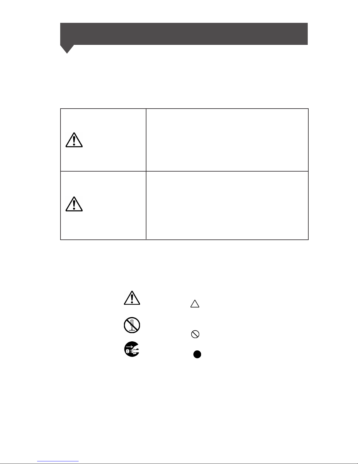
Example of symbols:
This symbol ( ) denotes items that require special care
while executing a certain procedure or operation.
This symbol (
) denotes items that are forbidden.
This symbol (
) denotes items you should follow to
prevent accidents or injury.
The example at left indicates “Unplug the power cable.”
Safety Precautions
The symbols listed below are used in this manual to ensure the
proper use of the printer and to prevent the printer from being
damaged.
Follow the instructions marked with these symbols.
Minor personal injury or product and/or
peripheral damage:
Failure to follow the guidelines marked with
this symbol could result in minor personal
injury or product and/or peripheral damage.
Serious personal injury or death:
Failure to follow the guidelines marked with
this symbol could result in serious personal
injury or death.
WARNING
CAUTION
Page 10
vi
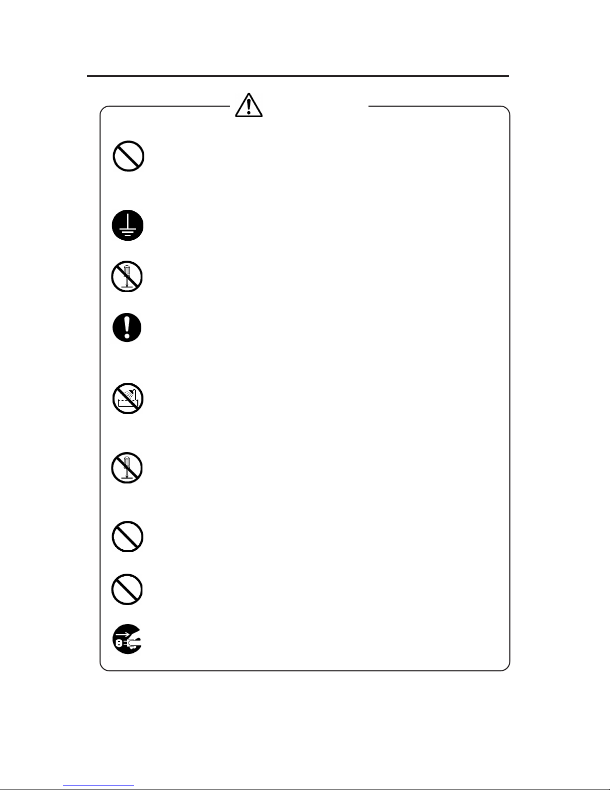
Use the power supply voltage specified on the nameplate. DO NOT
plug several devices into one electrical outlet as this might result in fire
or electric shock.
Make sure the printer is well grounded. If it is not, a short circuit may
cause fire or electrical shock.
DO NOT disassemble or remodel the printer. DO NOT repair the printer
by yourself. Doing so may cause fire, electric shock or other accidents.
DO NOT damage, break, process, or heat the power cable. If it is
damaged, replace it with a new one. Using a damaged power cable may
cause fire or electric shock.
NEVER use the printer in a place of extreme humidity or any place
where it can possibly be splashed by any liquids. Liquids which get into
the printer could cause fire, electric shock, or other serious accidents.
DO NOT remove the covers attached to the printer because they contain
high voltage and extremely hot parts. Careless removal might result in
an electric shock or burn.
DO NOT allow metal or liquids to touch the internal parts of the printer.
Doing so may cause fire, electric shock, or other accidents.
DO NOT disconnect or connect the power cable with wet hands. Doing
so may lead to electric shock.
Turn the printer OFF and unplug the power cable immediately if it sparks.
WARNING
Page 11
vii
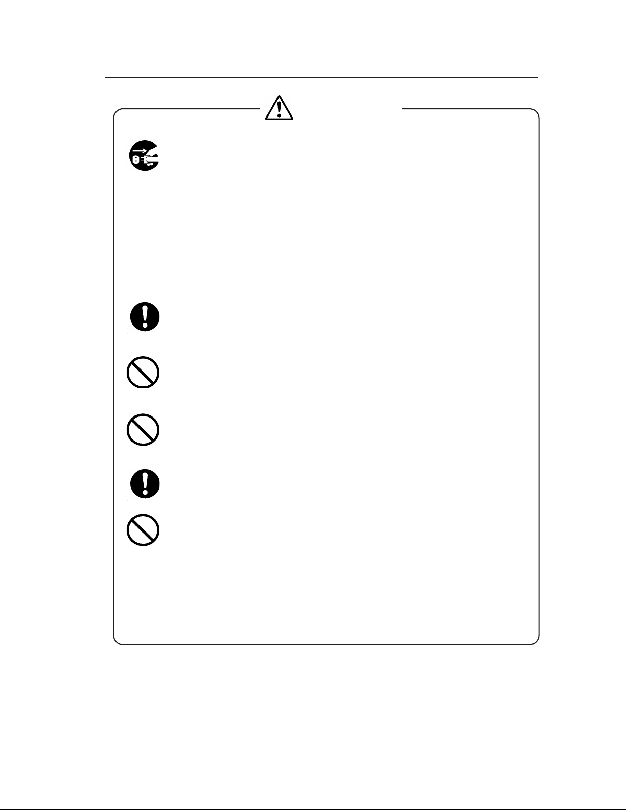
Turn power to the printer OFF and unplug the power cable from the
power outlet in the following cases:
•Before cleaning or maintenance.
• Smoke, strange noise or smells generate from the printer.
•A piece of metal or liquid touches the internal parts or slot of
the printer.
• An error requiring service by a service center occurs.
DO NOT put your hand into the paper discharge slot as it may be injured
by the cutting device.
Since the ink is flammable, never use fire near the device. It may cause
fire.
Do not swallow ink or permit it to splash on the eye. If it gets into the
eye, wash it off with clean running water and consult a doctor. If it is
swallowed, do not try to force vomiting, but consult a doctor.
Keep ink cartridges out of reach of children.
If ink adheres to the surface of the printer, promptly wipe it OFF. Leaving
it on may damage the coating.
WARNING
Page 12
viii
Handle the media rolls with care because they are very heavy. Dropping
them could lead to personal injury.
Hold the electric cable by the plug when connecting or disconnecting it.
Holding the cable directly may cause the cable to fray or break, which
could lead to electric shock and/or fire.
DO NOT get ink on your skin or clothes. Wash off any ink immediately
with soapy water.
DO NOT put any paper rolls on an unstable table or a tilted surface as
they could fall, causing injury.
The heater will be hot.
Be careful not to touch it and not to be burned.
In order to ensure the safe operation of the printer heed all of the cautions
and warnings contained throughout this manual.
CAUTION
Page 13

ix
Handling Precautions
Power Supply
1. Install the printer near an easily accessible electrical outlet.
2. Do not provide power to the printer through the same power
line as for noise-generating devices, such as a motor.
3. Use a power supply matched with the printer specification.
4. Connect the power cable directly to an electrical outlet. Do not
plug several devices into one electrical outlet.
Printer
1. Do not place anything on top of the printer. Do not rest your
elbows on the printer.
2. Open and close the top cover gently from the front of the printer
with both hands.
3. Before connecting or disconnecting the interface connector, turn
the printer OFF.
4. Do not clean the surface of the cover with benzene or paint
thinner. The coating may come off or deteriorate.
Wipe the cover clean with a soft cloth. If the cover is very dirty,
use a cloth moistened with a neutral detergent.
5. Do not touch the ink-jet head surface.
Regular Inspection and Maintenance
The following regular inspection and maintenance must be
performed in terms of characteristics of solvent ink:
1. Clean the capping unit and wiper blade every day.
2. Check moisture of wiper sponge every day.
3. Perform head cleaning every month.
4. Perform service cleaning when leaving the printer for a long
time (2 weeks or more with power OFF.)
5. Perform head washing and ink charging before printing after
leaving the printer idle for a long time.
See pages 2-68 and 2-82 for regular inspection and maintenance.
Page 14

x
Consumables
1. Always use the recommended consumables (media, ink, etc.).
Failure to follow this instruction may cause poor print quality
or breakdown.
2. Do not use ink past the expiration date as this may cause a
breakdown.
3. Put a used ink cartridge into a plastic bag and dispose of it as
industrial waste. Observe local regulations for disposal of waste
ink bottles.
4. Do not get ink on your skin or clothes. Wash any ink off
immediately with soapy water.
5. Check the waste ink bottle regularly so as not to permit waste
ink to leak.
6. When the waste ink bottle is installed or removed, spread a stain
preventing sheet so as not to stain the floor with spilt ink.
7. Store ink in a dark and cool place.
NEVER store ink in high temperature or direct sunshine.
Doing so may cause ink to deteriorate.
8. Do not attempt to disassemble ink cartridges.
9. Commercially available media for use with solvent ink can be
used in this printer.
Page 15
xi
Marks
Boxes marked with "WARNING" describe points requiring caution
to avoid serious personal injury.
Boxes marked with "CAUTION" describe points requiring caution
to avoid injury to yourself or damage to the printer.
Boxes marked with a note describe precautions while handling the
printer.
HINT: Hint mark
The hint symbol describes operations that make using or
handling the printer easier.
Reference mark
This mark is followed by a reference section or page number.
Manual Legend (Notational rules)
This manual uses the following notation for marks, keys, LCDs,
and LEDs:
NOTE
HINT
WARNING
CAUTION
Page 16
xii
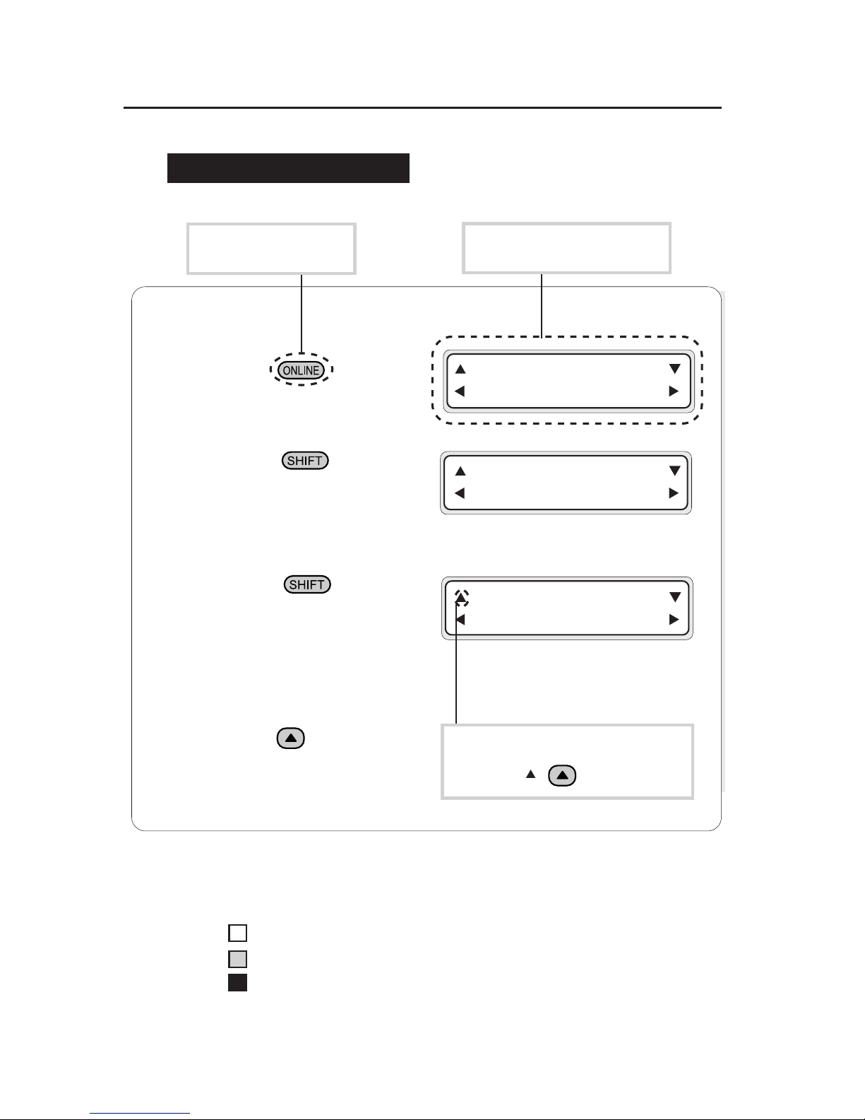
1 Press to put the
printer offline.
2 Press to select
the first menu in the
local operation mode.
3 Press again to
select the second menu
in the local operation
mode.
4 Press to enter the
function menu.
This represents a key
on the operation panel.
This represents the LCD on the
operation panel.
On
Flashing
Off
Example 2: LED states
The LED states "On", "flashing", and "Off" are indicated as follows:
Example 1: Keys in the text and display on the LCD
INK ENTRY
PAPER F. ADJ
SERVICE FEED
CLEANING
FUNC SYSTEM
ADJUST RESET
This represents a key to select the
menu. (Ex. :
key)
Notation for Keys/LCD/LED
Page 17
xiii
PRINT READY
ROLL : 104 / PAPER
INK ENTRY
PAPER F. ADJ
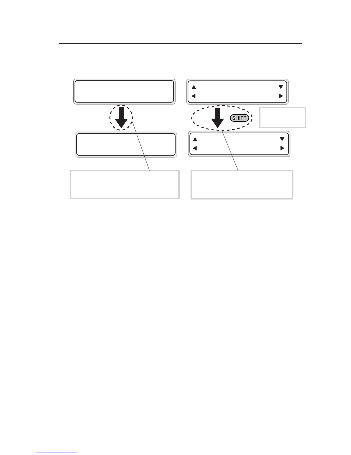
Example 3: LCD state transitions and key operations
A key on the
operation panel.
This indicates that the LCD screen
changes to another automatically without
pressing a key.
This shows that the LCD screen
changes to another when the operator
presses a key.
INITIALIZING
WAIT A MOMENT
SERVICE FEED
CLEANING
Page 18

CONTENTS-1
TABLE OF CONTENTS
Introduction
Contents of Package ........................................................................... i
Safety Precautions.............................................................................. v
Handling Precautions.......................................................................... ix
Manual Legend (Notational rules).......................................................xi
Section 1 Getting Started 1-1
Operating Conditions ....................................................................... 1-2
Installation Space ................................................................ 1-2
Environmental Conditions ................................................... 1-3
Consumables ................................................................................... 1-5
Media ................................................................................... 1-5
Ink Cartridge ........................................................................ 1-8
Waste Ink Bottle ................................................................ 1-11
Maintenance Kit ................................................................. 1-12
Cap Cleaning Liquid (6-Bottle Set) .................................... 1-12
Wiper Cleaning Liquid (6-Bottle Set) ................................. 1-13
Cleaning Swab .................................................................. 1-13
Storage Kit ......................................................................... 1-13
Cleaning Kit ....................................................................... 1-13
Liner .................................................................................. 1-14
Head Cleaning Sheet ........................................................ 1-14
External Views, Part Names, and Functions ................................. 1-15
Front View (Feeder unit) .................................................... 1-15
Rear View (Winder unit) .................................................... 1-16
Heater ................................................................................ 1-17
Operation Panel ................................................................ 1-18
Heater Control Panel ......................................................... 1-20
Dryer 100 (Option) ............................................................ 1-21
Footswitch (Option) .......................................................... 1-21
SCSI Cable (9 m) (Option) ............................................... 1-21
Page 19

CONTENTS-2
Main Scroller (Option) ...................................................... 1-21
Sub Scroller (Option) ........................................................ 1-21
Exhaust Attachment 100 (Option) .................................... 1-21
Tension Bar Set (Option) .................................................. 1-22
Peeling Bar Set (Option) .................................................. 1-22
Dual Roll Kit (Option) ........................................................ 1-22
Edge Guide (Option) ........................................................ 1-22
PS RIP (PhotoPrint 4 DX) (Option)................................... 1-22
PS RIP (PhotoPrint 4 Server) (Option) ............................. 1-22
Section 2 Basic Operations 2-1
Connecting to a Computer ............................................................... 2-2
System Configuration (Connection Example) ..................... 2-2
Connection Procedure ......................................................... 2-2
Turning the Power ON/OFF ............................................................. 2-5
Turning the Power ON ......................................................... 2-6
Turning the Power OFF 1 .................................................. 2-10
Turning the Power OFF 2 .................................................. 2-10
Installing/Removing the Media....................................................... 2-12
Installing Main Scroller ...................................................... 2-12
Media Setting .................................................................... 2-15
Installing the Sub Scroller .................................................. 2-21
Installing the Sub Scroller on the Printer ........................... 2-22
Installing or Removing the Cut Sheet ................................ 2-25
Installing the Media Roll in the Winder .............................. 2-27
Removing the Media Roll from the Printer ........................ 2-34
Replacing Media on Main Scroller ..................................... 2-35
Replacing Media on Sub Scroller ...................................... 2-35
Replacing Jammed Media Roll .......................................... 2-35
Paper Feed Correction Value Setting................................ 2-36
Page 20

CONTENTS-3
Replacing Ink Cartridges ............................................................... 2-41
Ink Cartridge Replacement Procedure .............................. 2-41
Replacing an Empty Ink Cartridge ..................................... 2-43
If an Ink Cartridge is not Installed ...................................... 2-44
Replacing Cartridges during Printing................................. 2-45
Replacing 4-Color Ink Cartridges ...................................... 2-47
If an Ink Cartridge is not Detected ..................................... 2-48
Replacing the Waste Ink Bottle...................................................... 2-49
Waste Ink Bottle Replacement Procedure ........................ 2-49
If the Waste Ink Bottle is Full ............................................. 2-51
If the Waste Ink Bottle is not Installed ............................... 2-52
Tension Bar Length Adjustment .................................................... 2-53
Head Cleaning "CLEANING" ......................................................... 2-55
Paper Feed "FEED" ....................................................................... 2-57
Using the Origin Point Setting Function ............................ 2-58
Changing Heater Control Setting Temperature ............................. 2-62
Using the Media Pressure Alternation Lever ................................. 2-65
Using the Head Up/Down Lever .................................................... 2-66
Using the Media Edge Guard ........................................................ 2-68
Using the Print Pause/Restart and Cancel Keys ........................... 2-69
Inspection & Maintenance ............................................................. 2-70
Regular inspection and maintenance guide ...................... 2-70
Daily inspection and maintenance ..................................... 2-71
Monthy inspection and maintenance ................................. 2-77
When leaving the printer for a long time (2 weeks or more) in power OFF state .....
2-77
When restarting the printer after a long absence (2 weeks or more) .......
2-78
When restarting the printer after a long absence (within 2 weeks) in power OFF state .
2-80
When leaving the printer with power OFF for one month or more .....
2-81
Cleaning ............................................................................ 2-82
Page 21

CONTENTS-4
Section 3 Operation Panel Menu Operations 3-1
LCD Messages and Printer State .................................................... 3-2
Display on the LCD ............................................................. 3-2
Operation in Online State ................................................................ 3-4
Basic Menu Operation in Offline State........................................... 3-10
Menu Hierarchical Structure .............................................. 3-10
Menu Tree ......................................................................... 3-11
Basic Operations and Keys ............................................... 3-17
Operation Procedure for Choice Input, Value Input,
Execution, and Character Input ......................................... 3-18
Menu Operations ........................................................................... 3-24
INK Menu .......................................................................... 3-24
PAPER Menu .................................................................... 3-25
ENTRY Menu .................................................................... 3-27
F.ADJ Menu....................................................................... 3-46
SERVICE Menu ................................................................. 3-49
CLEANING Menu .............................................................. 3-53
FEED Menu ....................................................................... 3-54
FUNC Menu....................................................................... 3-55
ADJUST Menu................................................................... 3-57
SYSTEM Menu .................................................................. 3-61
RESET Menu..................................................................... 3-66
Section 4 Special Printing 4-1
Special Printing ................................................................................ 4-2
Print Modes ......................................................................... 4-2
Double-Sided Printing ......................................................... 4-4
Mesh Tarpaulin Printing ...................................................... 4-4
Textile Printing ..................................................................... 4-4
Dual Roll Print ..................................................................... 4-4
Page 22

CONTENTS-5
Double-Sided Printing ...................................................................... 4-5
Types of Double-Sided Printing ........................................... 4-5
Printing on Back Side from Winding unit ............................. 4-5
Printing on Back Side from Paper Feeder ......................... 4-12
Printing on Back Side
from Paper Feeder After Rewinding .................................. 4-20
Using the Liner .................................................................. 4-25
Printing on Mesh Tarpaulin ............................................................ 4-35
Section 5 Heater Controller Menu Operation 5-1
Temperature Control........................................................................ 5-2
LCD Display ..................................................................................... 5-4
Parameter Setup Mode.................................................................... 5-6
Error Messages ............................................................................. 5-10
Section 6 Troubleshooting 6-1
Troubleshooting ............................................................................... 6-2
Clearing Jams .................................................................................. 6-3
When an Error Message Appears ................................................... 6-4
Service Call Errors............................................................... 6-4
Communication Errors ......................................................... 6-6
Operator Call Errors ............................................................ 6-7
When the Printer Fails to Work Correctly ...................................... 6-12
When a Print Error Occurs............................................................. 6-13
When There is an Abnormal Sound............................................... 6-14
When It is Desired to Move the Printer .......................................... 6-15
Appendix A-1
Basic Specifications ......................................................................... A-2
Printer Specifications ........................................................... A-2
Page 23

1-1
Section 1 Getting Started (Basic knowledge)
Section 1 Getting Started
(Basic knowledge)
This section provides necessary information to operate the
printer. Familiarize yourself with the basics of the printer
before reading Section 2 and later.
Operating Conditions
Consumables
External Views, Part Names, and Functions
Contents of this section
Page 24
1-2
Operating Conditions
This section describes the operating conditions for the printer.
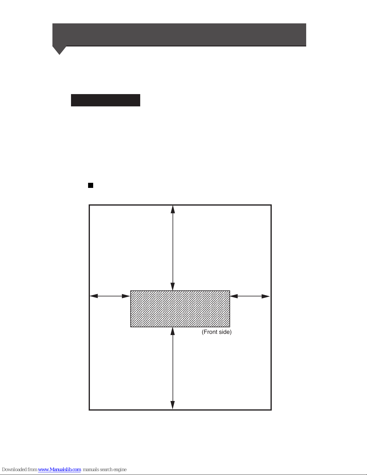
Installation Space
There must be sufficient space around the printer for the replacement
of frequently used parts, for the output of drawings, and for
ventilation. In addition, maintenance space, shown below, is
required to repair the printer or replace components.
The installation/maintenance space is shown in the following figure:
Installation and maintenance space
Height direction: 1700
(Unit : mm)
400
400
1000
1000
23456789012345678901234567890121234567890123
4
23456789012345678901234567890121234567890123
4
23456789012345678901234567890121234567890123
4
23456789012345678901234567890121234567890123
4
23456789012345678901234567890121234567890123
4
23456789012345678901234567890121234567890123
4
23456789012345678901234567890121234567890123
4
23456789012345678901234567890121234567890123
4
23456789012345678901234567890121234567890123
4
23456789012345678901234567890121234567890123
4
23456789012345678901234567890121234567890123
4
23456789012345678901234567890121234567890123
4
23456789012345678901234567890121234567890123
4
23456789012345678901234567890121234567890123
4
23456789012345678901234567890121234567890123
4
(Front side)
Page 25

1-3
Section 1 Getting Started (Basic knowledge)
Operating Conditions
Environmental Conditions
Operating temperature and humidity levels
The printer should be used within the temperature and humidity
ranges shown below.
Temperature: 15 °C to 30 °C
Humidity: 30% to 70%
-To obtain better print quality, use the printer within
temperatures of 20° to 25 °C.
- When the operating temperature is lower than 20 °C or
higher than 40 °C, print speed is reduced to two-thirds of
normal print speed to maintain good print quality.
HINT
NOTE
- When the printer is used out of range of the operating
temperature and humidity, printing may stop or print quality
may be degraded.
Page 26

1-4
Places where the printer must not be installed
Do not install the printer in the following places:
- A location near fire
- Places exposed to direct sunlight
- Places subject to vibration
- Places with excessive dust
- Places subject to extreme changes in temperature or humidity
- Places near an air conditioner or a heater
- Places where the printer may get wet
- Places subject to direct air circulation from vents
- Places near a diazo copier that may generate ammonia gas
- Places with poor ventilation
- Unstable places
Page 27

1-5
Section 1 Getting Started (Basic knowledge)
Media
Available media types
The following types of media are available:
For details, ask our sales office or a nearby agent.
•Vinyl chloride
•FF
•Tarpaulin
• Mesh tarpaulin
•Fabric banner (cloth)
Contact our service center for details.
Consumables
Precautions for storing media
-Avoid direct sunlight and water both before and after opening
the package. Put media in a box or envelope to prevent dust and
store media in a dry, cool and dark place.
-Avoid rapid change of temperature and humidity, and store
media where condensation will not occur.
- Do not store media standing on end to prevent disorder of media
and damage to the roll edge.
- Do not pile up media rolls.
Precautions for disposing of media
- Dispose of media in accordance with local conditions and
regulations.
Page 28

1-6
Precautions in use
-Avoid change of temperature or humidity after opening the
package.
Set media in the printer after leaving media in the operation
environment for 3 hours or more. Suppress change of humidity
by turning the air conditioner ON/OFF.
- Due to media characteristics, curling of media in low humidity
and wrinkling of media in high humidity may occur easily.
Use media in a normal temperature and humidity environment
(around 23 °C and 50%RH).
- Do not use scratched, wrinkled, curled, or dust-stained part of
media.
Especially, damaged edges (both edges) affect media feeding.
Also, do not drop or wet the media. Doing so may adversely
affect print quality and cause malfunctioning.
- Hold margins of the media so as not to touch the print surface.
Adhesion of sebaceous matter or sweat may adversely affect
print quality.
- Roll media correctly before setting in the printer.
Precautions for handling prints.
- Do not touch the print surface before ink dries.
Hold margins of the media for handling.
Especially use care within 24 hours after printing.
- Rubbing the print surface causes color fading or color transfer.
Do not superimpose print surfaces, to prevent color transfer.
- Do not superimpose on copy prints or laser prints, to prevent
sticking due to ink or toner.
- Do not rub, scratch, or hold the media, to prevent peeling.
- Do not rub or leave the media in wet condition, to prevent
blurring.
Page 29

1-7
Section 1 Getting Started (Basic knowledge)
Consumables
Other precautions
- Aging of media causes color fading and a change in quality.
Check media condition and use well-conditioned media.
- Media dust due to cutting may cause floating of laminated
coating.
- When using media with glue, adhesive matter (glue) may stick
to the platen.
In this case, wipe up the adhesive matter, referring to "Section 2
Inspection & Maintenance".
Sticking of adhesive matter may cause paper jamming.
Page 30
1-8
Ink Cartridge
Ink types
Use our recommended ink cartridges listed below.
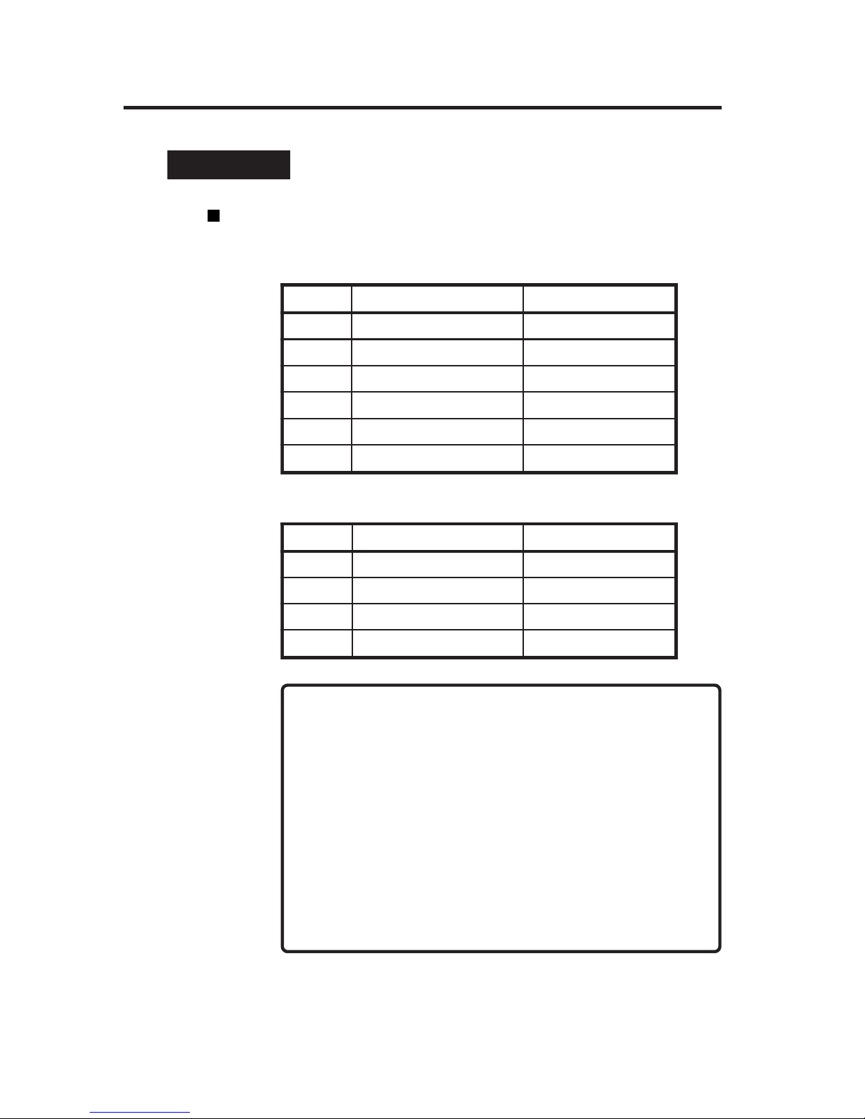
[6-color ink cartridge] 1 cartridge/box
NOTES
- Failure to use the recommended ink cartridge may lead to
deterioration of print quality or printer malfunction.
- The ink lifetime is 12 months after the manufacture date.
- Do not shake ink cartridges before use.
- All six color cartridges must be installed.
If any of the cartridges is removed, install a new one.
Item No. Ink color Ink capacity
IP6-101 Y (Yellow) 1000 ml
IP6-102 M (Magenta) 1000 ml
IP6-103 C (Cyan) 1000 ml
IP6-104 Bk (Black) 1000 ml
IP6-105 Lc (Light Cyan) 1000 ml
IP6-106 Lm (Light Magenta) 1000 ml
Item No. Ink color Ink capacity
IP6-141 Y (Yellow) 1000 ml
IP6-142 M (Magenta) 1000 ml
IP6-143 C (Cyan) 1000 ml
IP6-144 Bk (Black) 1000 ml
[4-color ink cartridge] 3 cartridge/box
Page 31
1-9
Section 1 Getting Started (Basic knowledge)
Consumables
CAUTION
WARNING
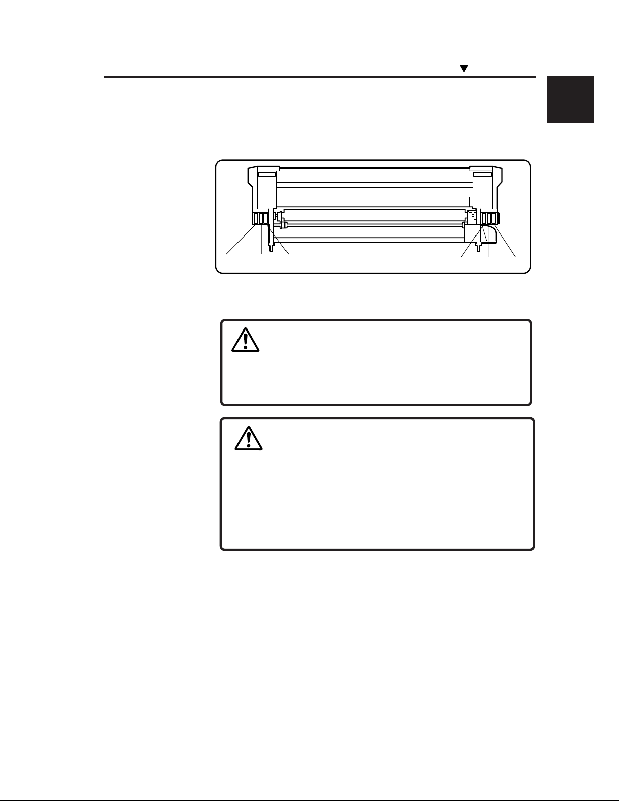
Ink cartridges must be installed in all six slots. The positions of ink
cartridges are specified by color. (See the figure below.)
Black Light Magenta Light Cyan Yellow Magenta Cyan
- Never bring the ink close to fire. Failure to follow this warning
might result in fire.
- Do not swallow ink or let it splash on the eye. If it gets into
the eye, wash it off with clean running water and consult a
doctor. If it is swallowed, do not try to force vomiting, but see
a doctor.
- Do not attempt to disassemble ink cartridges.
Page 32
1-10
NOTE
Precautions for ink storage and processing
- Securely put a used ink cartridge into a plastic bag and
dispose of it as industrial waste. Observe regulations for
disposal of ink cartridges.
- Ink has an expiration date. After expiration, the print quality
may deteriorate or the printer may malfunction.
- Store ink cartridges in a dry, cool and dark place.
Always use the recommended ink. Failure to follow this
instruction may cause poor print quality or a breakdown.
CAUTION
Page 33
1-11
Section 1 Getting Started (Basic knowledge)
Consumables
WARNING
- Do not swallow ink or let it splash on the eye. If it gets into
the eye, wash it off with clean running water and consult a
doctor. If it is swallowed, do not try to force vomiting, but see
a doctor.
- Install the waste ink bottle securely.
- A waste ink bottle must always be installed. If it is removed
for replacement, a new one must be installed.
CAUTION
NOTE
- Never put the waste ink bottle near an open flame. Failure
to follow this warning might result in fire.
Item No. Remarks
IP6-109 1 piece
Waste Ink Bottle
Use our recommended waste ink bottle listed below.
Precautions for handling the waste ink bottle
- After use, securely fasten the attached cap and dispose of
the waste ink bottle as industrial waste.
CAUTION
Page 34
1-12
Item No. Remarks Quantity
IP6-138 Cap cleaning liquid (100ml) 6
Cap Cleaning Liquid 6-Bottle Set
Maintenance Kit
For cleaning the cap and wiper, use our specified cleaning liquid
listed below.
Item No. Remarks Quantity
IP6-108
Cap cleaning liquid 100 ml
Wiper cleaning liquid 100 ml
Cleaning swab 50 pieces
Syringe 10 pieces
- Do not swallow ink or let it splash on the eye. If it gets into
the eye, wash it off with clean running water and consult a
doctor. If it is swallowed, do not try to force vomiting, but see
a doctor.
CAUTION
NOTE
- When the waste ink bottle is installed or removed, hold it
with both hands with its mouth facing up. If not, waste ink
may spill from the bottle.
Page 35
1-13
Section 1 Getting Started (Basic knowledge)
Consumables
Wiper Cleaning Liquid 6-Bottle Set
Item No. Remarks Quantity
IP6-139
Wiper cleaning liquid (100ml) 6
Syring 10
Storage Kit
Cleaning Kit
Item No. Remarks Quantity
IP6-117
Cleaning liquid cartridge (IP6-119) 6
Dummy cartridge (IP6-118) 6
Item No. Remarks Quantity
IP6-137
Maintenance liquid cartridge (IP6-107) 6
Dummy cartridge (IP6-118) 6
Cleaning Swab
Item No. Remarks
IP6-147 300 pieces
Page 36

1-14
Head Cleaning Sheet
Liner
Item No. Remarks Quantity
IP6-161 Liner 1 piece
Item No. Remarks Quantity
IP6-148 Head cleaning sheet 6 sheets
Page 37
1-15
Section 1 Getting Started (Basic knowledge)
External Views, Part Names, and Functions
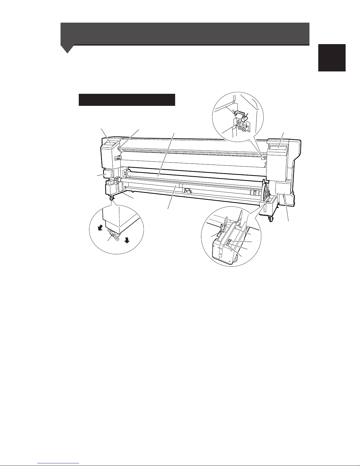
This section shows external views of the printer and names of
printer parts, and describes their functions.
Front View (FeedingSide)
(1) Operation panel The lamps and LCD, which indicate the printer status, and keys for
setting functions are located on the operation panel.
(⇒See page 1-18)
(2) Heater control panel The keys for setting heater temperature are located on the heater
control panel. (⇒See page 1-20)
(3) Ink holder Holds the ink cartridge.
(4) Tension bar guide (⇒See page 2-15)
(5) Caster Unlock the caster to move the printer, and locks it to secure the
printer.
(6) Paper pressure alternation lever Alternates media pressure depending on the media thickness.
(⇒See page 2-65)
(7) Pressure roller up/down lever Presses down and releases media inserted in the feeding unit.
(8) Feed direction switch1 (⇒See page 2-16)
(9) Take-up Switch (⇒See page 2-16)
(10) Feed Switch (⇒See page 2-16)
(11) Sub scroller (⇒See page 2-21)
(12) Footswitch connector Connects the footswitch (option). (⇒See page 1-20)
Lock
Unlock
(1)
(7)
(2)
Main scroller
(5)
(6)
(3)
(3)
(4)
(8)
(4)
(9)
(10)
(12)
(11)
Page 38
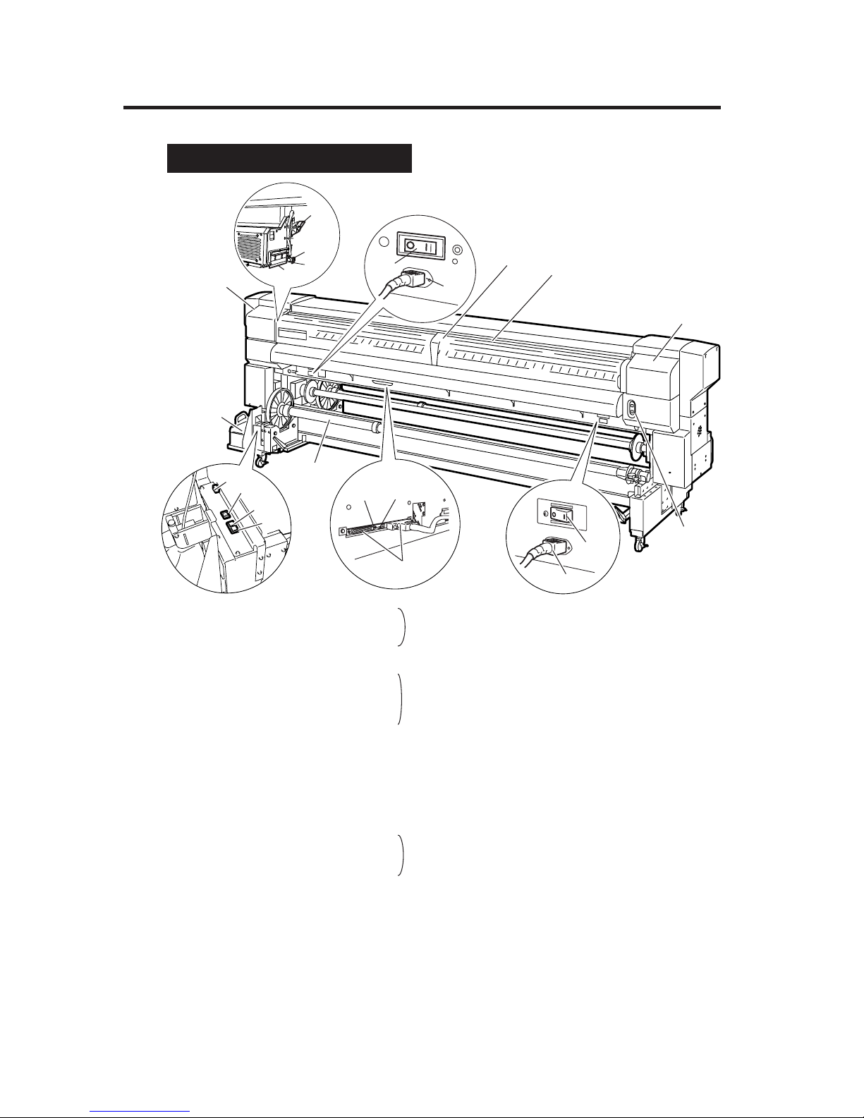
1-16
(13) Power receptacle
(14) AC1 switch
(15) Rear cover
(16) SCSI connector
(17) ID switch SCSI controller
(18) Terminator switch
(19) Paper outlet
(20) Waste ink bottle
(21) Head Up/Down lever
(22) Shield HB
(23) Brush
(24) Power receptacle
(25) AC2 switch
(26) Cap cover
(27) Wiper cover
(28) Print stop/restart, cancel keys (⇒See page 2-69)
(29) Take-up direction switch (⇒See page 2-28)
(30) Feed switch (white) (⇒See page 2-28)
(31) Winder switch (green) (⇒See page 2-28)
(32) Footswitch connector (⇒See page 1-21)
RearRear View(DischargeSide)
(17)
(25)
(29)
(16)
AC2
(26)
(20)
(15)
(19)
(27)
(28)
AC1
(24)
(18)
(14)
(13)
(30)
(31)
(32)
Main scroller
(21)
(23)
(22)
Page 39
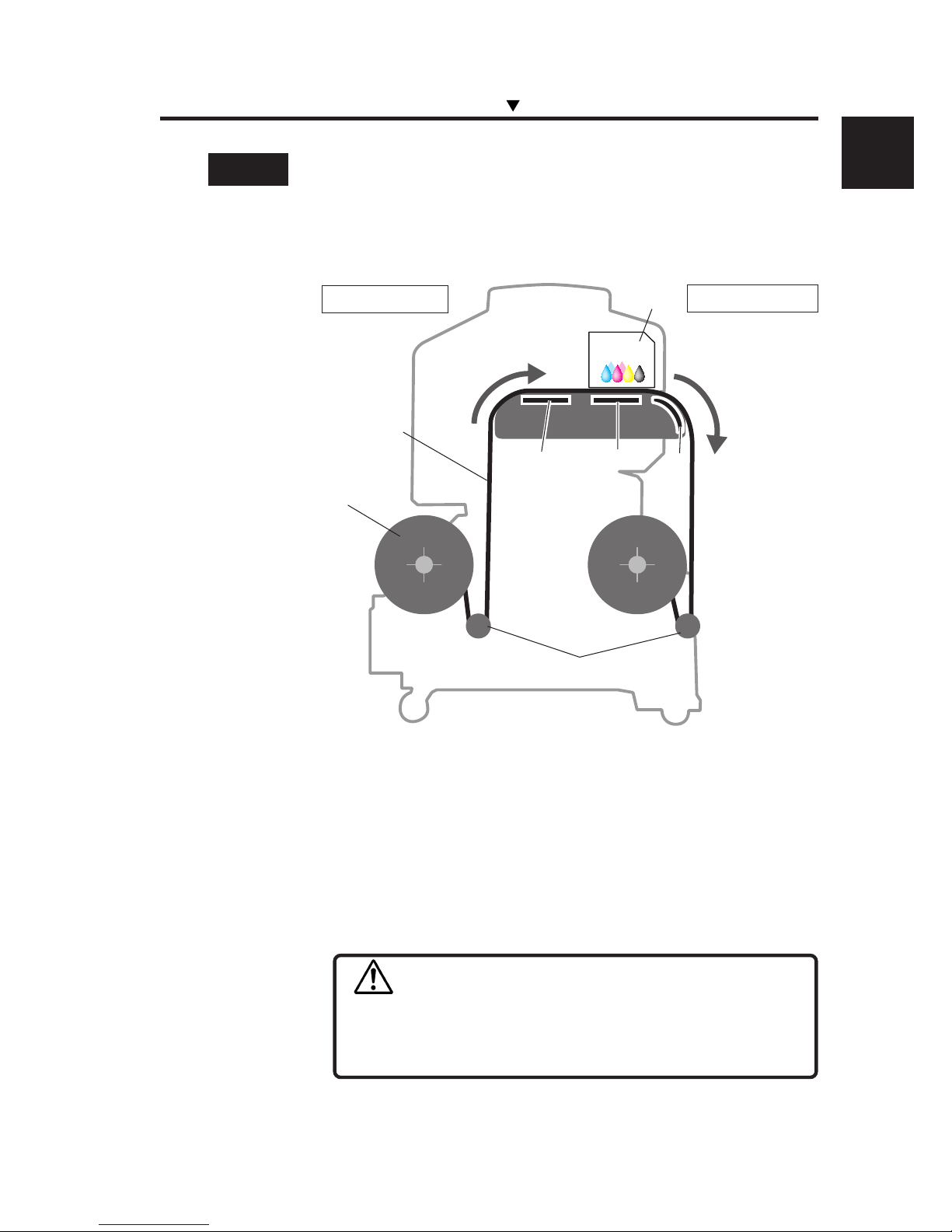
1-17
Section 1 Getting Started (Basic knowledge)
Heater Å
The printer has three built-in heaters for fixing and stabilizing the
print image on the print media.
(1) Front heater (Front) Preheats the media.
(2) Print heater (Rear) Infiltrates ink into the media and fixes ink.
(3) Rear heater (Finish) Dries ink and stabilizes print image.
* The three heaters are controlled separately.
The heater temperature can be controlled from the operation panel and host
PC (RIP).
(⇒See page 2-60 “Changing Heater Control Setting Temperature”)
WARNING
- Heaters become hot.
NEVER touch the heaters. Doing so could cause a
burn.
External Views, Part Names, and Functions
Media
Main scroller
Paper feed
direction
Media outlet side
Head
Tension bar
Media inlet side
(1)
(2)
(3)
Page 40
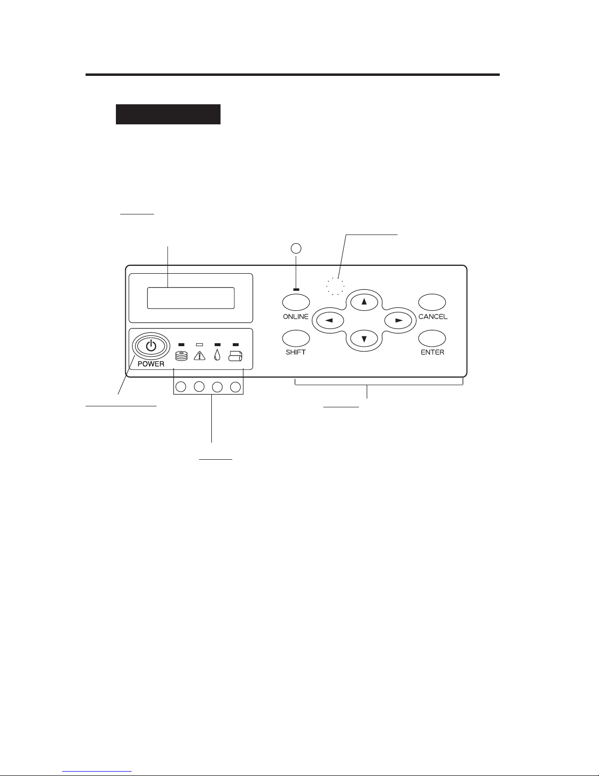
1-18
Operation Panel
Keys, LED, and the LCD are laid out on the operation panel as
shown below. A buzzer sounds to alert the user to errors or invalid
key operations.
(3) Power switch
Turns the printer ON
or OFF.
(2) Keys
Used to set printer functions.
(4) LCD
Shows the printer status
and menus.
(1) LED
The LEDs light, flash, or turn off
according to the status of the
printer.
B
C D
E
A
(5) Buzzer
Page 41
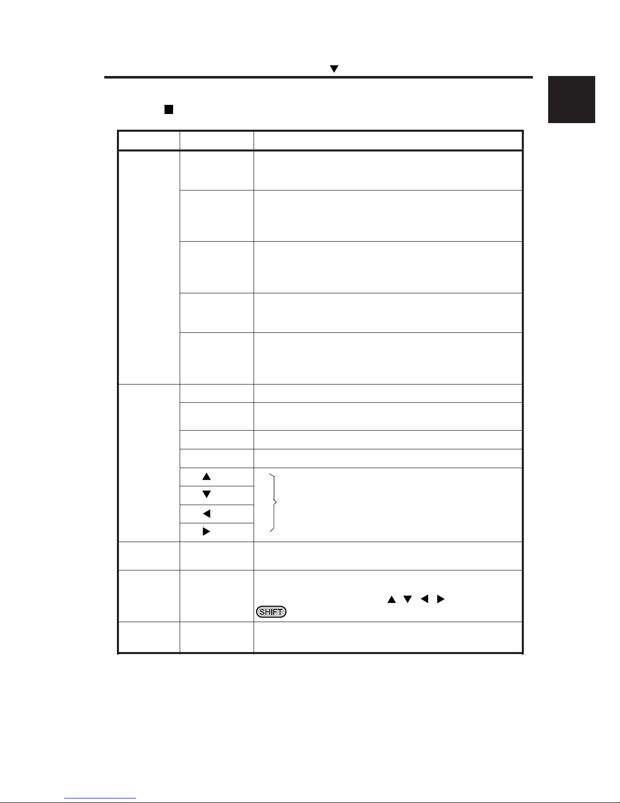
1-19
Section 1 Getting Started (Basic knowledge)
rebmuNemaNnoitcnuF
)1(
DEL
DELataD)A(
)neerg(
.etatsnoitpeceratadehtswohS
retupmocehtmorfdeviecergnieberaataD:gnihsalF-
deviecergnieberaatadoN:ffO-
DELrorrE)B(
)egnaro(
.derruccosahrorrenarehtehwsetacidnI
derruccosahrorrenA:nO-
)rorretuoemitredniW(etatsgninraW:gnihsalF-
).derruccosahrorreoN(lamroN:ffO-
DELknI)C(
)neerg(
.gninrawasetacidniroegirtrackninasierehtrehtehwswohS
.tneserperasegdirtracknillA:nO-
).tuonursahsknirolocehtfoenO(.tuogninnursiknI:gnihsalF-
).tuonursahsknirolocehtfoenO(knioN:ffO-
DELaideM)D(
)neerg(
.tessiaidemrehtehwswohS
).tessiteehstucrorepaplloR(.tessiaideM:nO-
).tessiteehstucronrepapllorrehtieN(aidemoN:ffO-
DELenilnO)E(
)neerg(
.enilfforoenilnosiretnirpehtrehtehwswohS
enilnO:nO-
edomesuapenilnO:gnihsalF-
enilffO:ffO-
)2(
yeK
yekENILNO.setatsenilffodnaenilnoneewtebsehctiwS
yekTFIHS
levelunemehtsehctiws(tupniretemaraprofyekyrailixuanasadesU
.)yalpsid
yekLECNAC.retemaraptupninaslecnaC
yekRETNE.retemarapasretnerounemastceleS
yek
unemehtsehctiwsropuorgunemehtstceleS
.)nwod/purebmun,noitceles(
yek
yek
yek
)3(
hctiwsrewoP
hctiwSrewoP.FFOroNOretnirpehtnrutotdesU
)4(
DCL
DCL
,sretcarahcciremunahplahtiwsutatsrosegassemretnirpswohS
lacihcrareihaevahsuneM.)senilowt,stigid61(slobmysro,anakatak
ro,,,htiwunemhcaesseccA.erutcurts
.yek
)5(
rezzuB
rezzuB.rorrenaforotarepoehtyfitonotmralanasdnuoS
Functions of LCD, LED and keys
External Views, Part Names, and Functions
Page 42
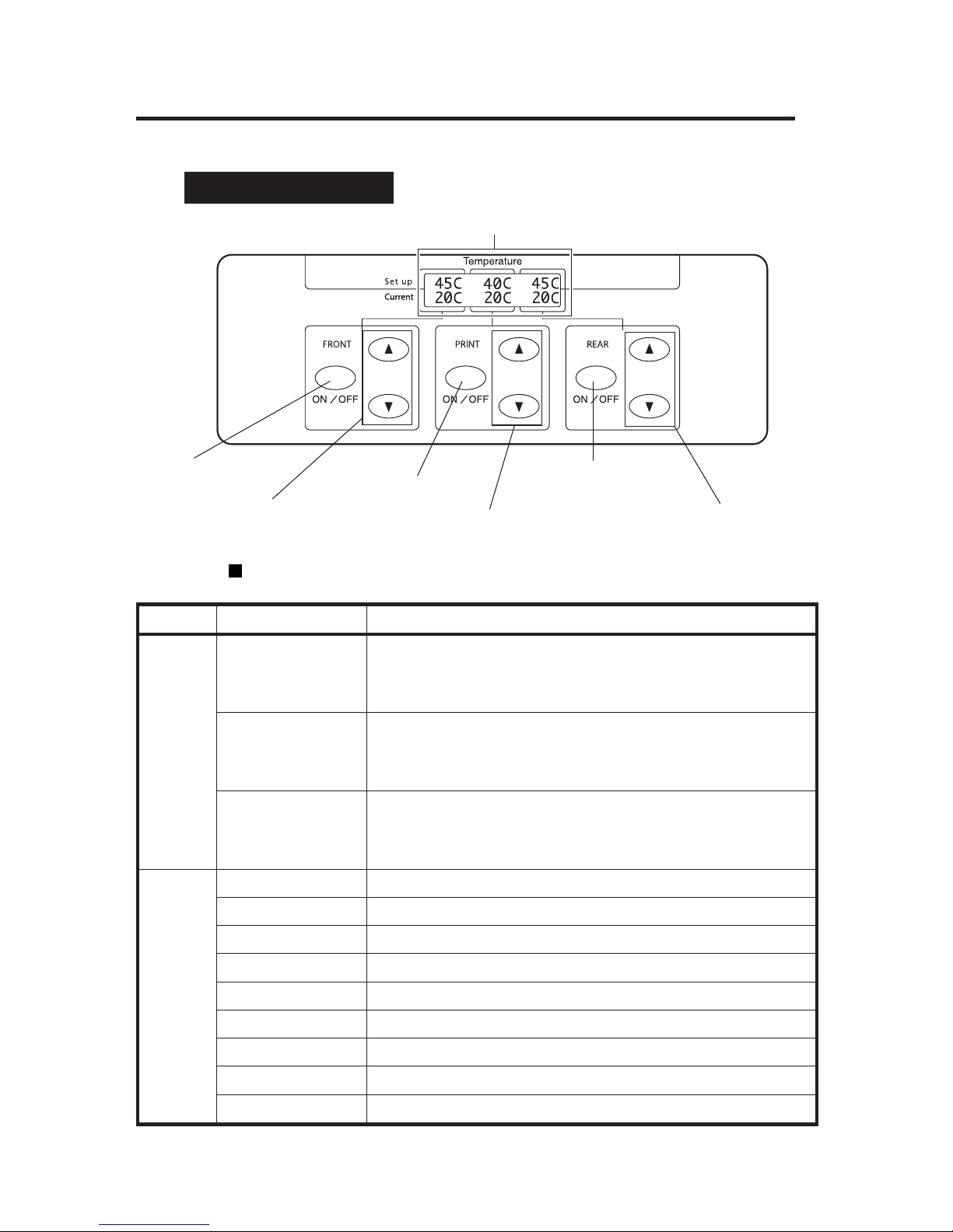
1-20
Heater Control Panel Å
Functions of LCD, LEDs and keys
LCD
Print Heater ON/OFF key
Print Heater UP/DOWN key
Front Heater ON/OFF key
Front Heater UP/DOWN key
Rear Heater ON/OFF key
Rear Heater UP/DOWN key
Number Name Function and description
LCD
FRONT
Indicates the setting temperature and the current temperature of the
front heater. When the main switch of the heater is turned off, a
message instructs the user to turn the main switch ON. When the front
heater is turned off, "OFF" is indicated.
PRINT
Indicates the setting temperature and the current temperature of the
print heater. When the main switch of the heater is turned OFF, a
message instructs the user to turn the main switch ON.
When the print heater is turned off, "OFF" is indicated.
REAR
Indicates the setting temperature and the current temperature of the rear
heater. When the main switch of the heater is turned off, a message
insturucts the user to turn the main switch ON.
When the rear heater is turned off, "OFF" is indicated.
key
FRONT ON/OFF key Turns the front heater ON/OFF.
FRONT UP key Increases the setting value for the front heater.
FRONT DOWN key Decreases the setting value for the front heater.
PRINT ON/OFF key Turns the print heater ON/OFF.
PRINT UP key Increases the setting value for the print heater.
PRINT DOWN key Decreases the setting value for the print heater.
REAR ON/OFF key Turns the rear heater ON/OFF.
REAR UP key Increases the setting value for the rear heater.
REAR DOWN key Decreases the setting value for the rear heater.
Page 43

1-21
Section 1 Getting Started (Basic knowledge)
Dryer 100 (Option)
The dryer 100 dries the output media.
Footswitch (Option)
Operates the functions of the take-up switch and feed switch of the
paper feeder and the winder by foot.
SCSI Cable (9 m) (Option)
Connects the printer to the host PC. It is longer than the standard
cable by 3 m.
Main Scroller (Option)
Used in common for the feeder and the winder.
Sub Scroller (Option)
Used for the liner and sub roll.
Exhaust Attachment 100 (Option)
Attached to the printer to mount an exhaust duct.
External Views, Part Names, and Functions
Page 44

1-22
Tension Bar Set (Option)
Peeling Bar Set (Option)
Peels sticky media.
Dual Roll Kit (Option)
Additional parts to feed dual rolls.
Edge Guide (Option)
Retains the media when the liner is used.
PS RIP (PhotoPrint 4 DX) (Option)
PS RIP (PhotoPrint 4 Server) (Option)
RIP software for the IP-6900.
Page 45

2-1
Section 2 Basic Operations
Contents of this section
Section 2 Basic Operations
Connecting to a Computer
Turning the Power ON/OFF
Installing/Removing the Media
Replacing Ink Cartridges
Replacing the Waste Ink Bottle
Tension Bar Length Adjustment
Head Cleaning "CLEANING"
Paper Feed "FEED"
Using the Origin Point Setting Function
Changing Heater Control Setting Temperature
Using the Media Pressure Alternation Lever
Using the Head Up/Down Lever
Using the Media Edge Guard
Using the Print Pause/Restart and Cancel Keys
Inspection & Maintenance
Page 46
2-2
Connecting to a Computer
This section describes how to connect the printer to a computer.
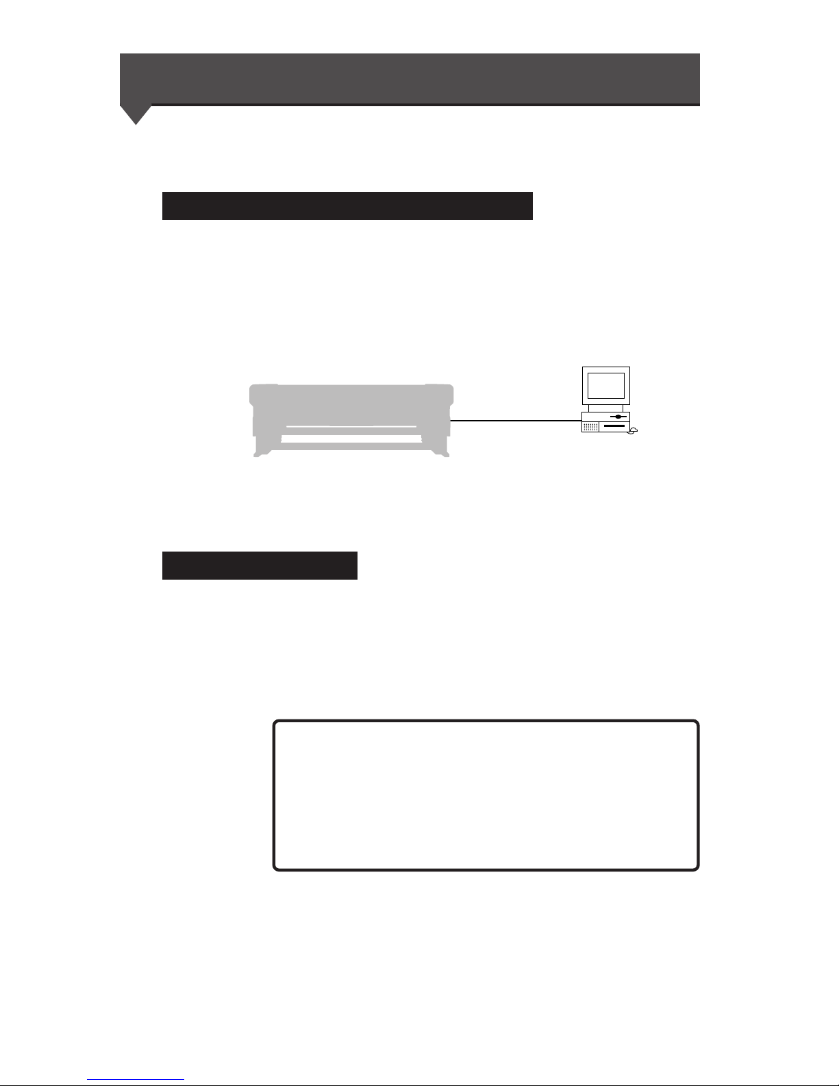
System Configuration (Connection Example)
The following is a typical connection:
Connection Procedure
Connect the cable as follows:
1 Turn the printer and the computer OFF.
Printer
(Printer server)
SCSI interface
NOTE
- When the printer is connected to the computer, turn the printer
ON, and then turn the computer ON. To turn the system
OFF, turn the computer OFF, and then turn the printer OFF.
Page 47
2-3
Section 2 Basic Operations
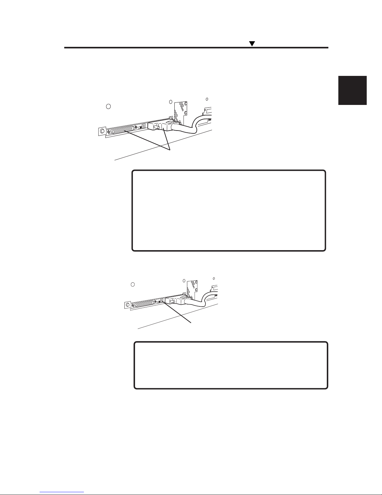
3 Set the SCSI ID switch on the rear of the printer.
- The ID number must be unique in the SCSI chain. (Initial
setting: 4)
SCSI ID switch
Set the SCSI ID number with a small
slotted screwdriver. (Initial ID value: 4)
2 Connect a SCSI cable to either of the SCSI connectors
on the rear of the printer.
Connecting to a Computer
NOTE
(It can be connected to either of two SCSI
connectors.)
NOTE
- Use a dedicated SCSI cable (68-68-pin, 6 m) or optional
SCSI cable (68-68-pin, 9m).
If any other cable is used, the radio wave level may
increase, in particularly the printer might not satisfy FCC
and CE regulations.
SCSI connector
Page 48
2-4
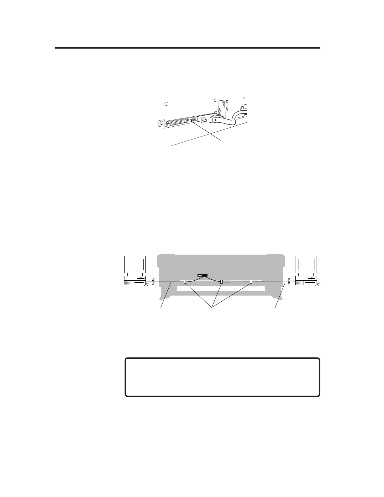
4 Set the terminator on the rear of the printer to ON or OFF.
The printer has a SCSI terminator ON/OFF function. If the printer is the
terminal device in the SCSI chain (only one SCSI connector is connected),
set the terminator switch to ON. If the printer is not the terminal device, set
it to OFF.
5 Secure the cable to the clamp.
Secure the SCSI cable to either side according to the installation position of
the printer and computer.
Terminator switch
NOTE
-Take care not to allow the SCSI cable to touch the media.
SCSI cable
SCSI cable
Clamp
Page 49
2-5
Section 2 Basic Operations
Turning the Power ON/OFF
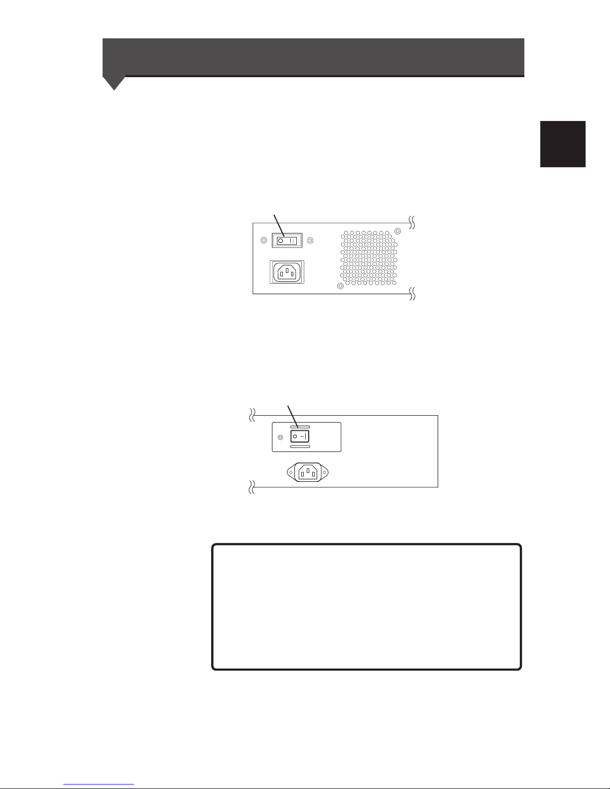
This printer has two power supply systems. Be careful that both are
200V.
AC1 switch
The AC1 switch is located on the printer rear (left side).
AC2 switch
The AC2 switch is located on the printer rear (right side).
NOTES
- When the printer is connected to the computer, turn the
printer ON, and then turn the computer ON. To turn the
system OFF, turn the computer OFF, and then turn the
printer OFF.
-Turn the computer ON after the printer is in the online state.
Printer rear (Right side)
AC1
Printer rear (left side)
AC2
Page 50
2-6
Turning the Power ON
<Power ON Procedure>
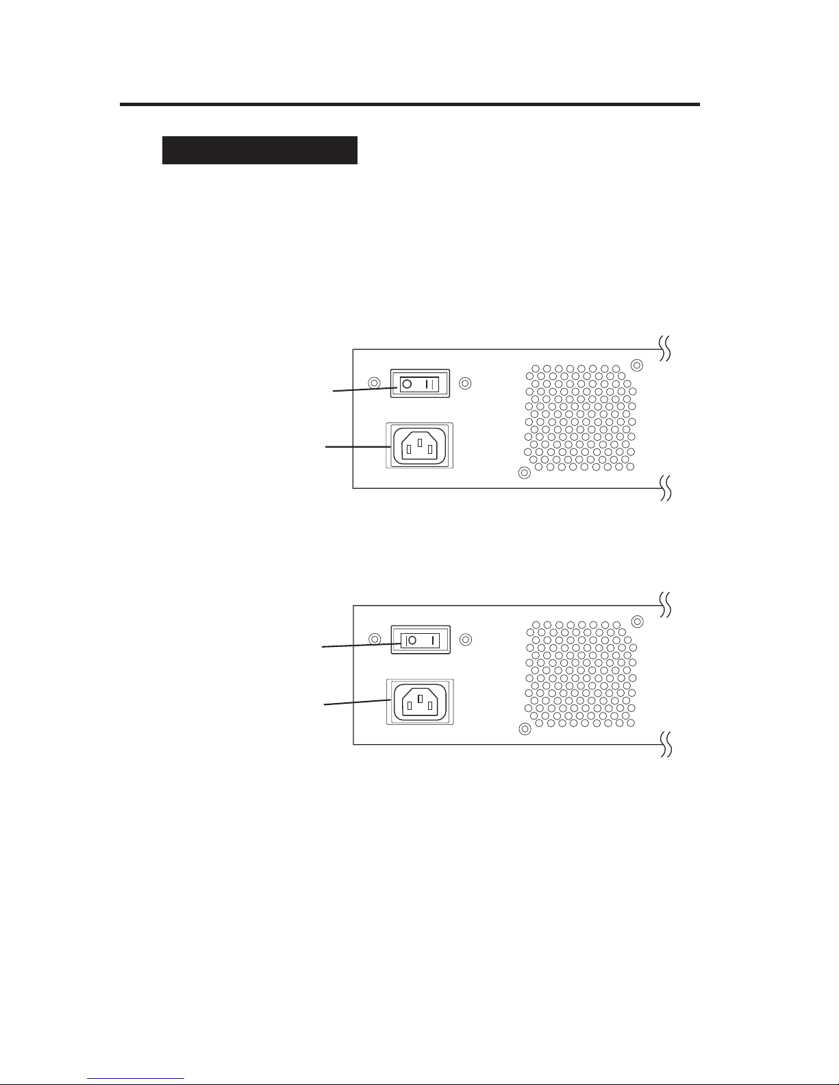
1 Turn the AC1 switch on the left rear of the printer OFF
(0), and plug one end of the supplied power cable into the
AC1 socket. Insert the other power plug of the cable into
an electrical outlet.
2 Turn the AC1 switch on the left rear of the printer ON (1).
Printer switch
OFF (0)
Socket
Printer switch
ON (1)
Socket
Page 51
2-7
Section 2 Basic Operations
Turning the Power ON/OFF
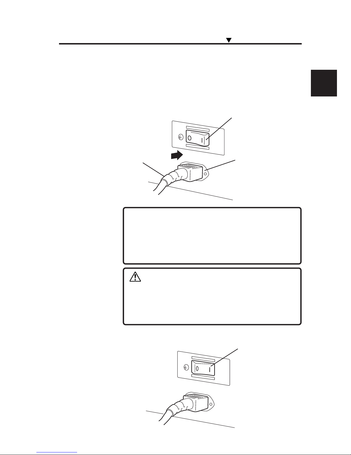
3 Turn the AC 2 switch on the right rear of the printer OFF
(0), and plug one end of the supplied power cable into the
AC 2 socket. Insert the other power plug of the cable into
an electrical outlet.
4
Turn the AC 2 switch on the right rear of the printer ON (1)
.
Power cable
NOTES
- Do not use a power cable other than the one specified for
this printer.
- The supplied power cable is for 200VAC. The shape of the
plug is different from the plug for 100VAC.
Printer switch OFF (0)
Socket
Printer switch ON (1)
CAUTION
- Fix the power cable in place using a clamp. If this is not
done, the power cable can be wound up in the scroller,
possibly causing electric shock and damage to the
equipment.
Page 52
2-8
Booting
PRINT READY
ROLL : 104 / PAPER
INITIALIZING
WAIT A MOMENT
If a 104" media roll is used
CHECK AC2
POWER OFF / ON
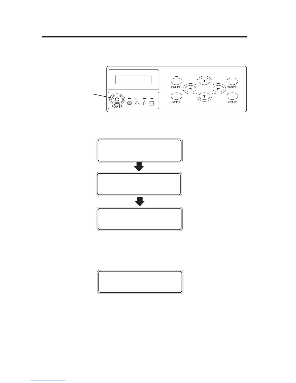
5 Turn the power ON/OFF switch on the operation panel ON.
When the switch is turned ON, a power-on self-diagnostic test is performed
and the following message appears on the LCD on the operation panel:
Power ON/OFF
switch
If the POWER ON/OFF switch on the operation panel is turned ON with
the AC2 switch in the OFF position, the following message is displayed on
the operation panel:
Turn the AC2 switch ON, and then turn the POWER switch ON again.
Page 53

2-9
Section 2 Basic Operations
Turning the Power ON/OFF
NOTE
- Turn the printer OFF while “PRINT READY” is displayed on
the LCD panel except in an emergency.
Do not turn the printer OFF while “INITIALIZING” or
“CLEANING” is displayed on the LCD panel to avoid dripping
of the ink and damage of the head. Saved parameters may
be lost.
- If the fan does not run or the operation panel lamp does not
light when the AC1 switch and power ON/OFF switch on the
operational panel are turned ON, the power supply may be
faulty.
- If an error is detected during the self-diagnostic test at power
ON, an error message appears on the LCD. See Section 5,
Troubleshooting, and take appropriate action.
HINT
Page 54
2-10
Turning the Power OFF 1
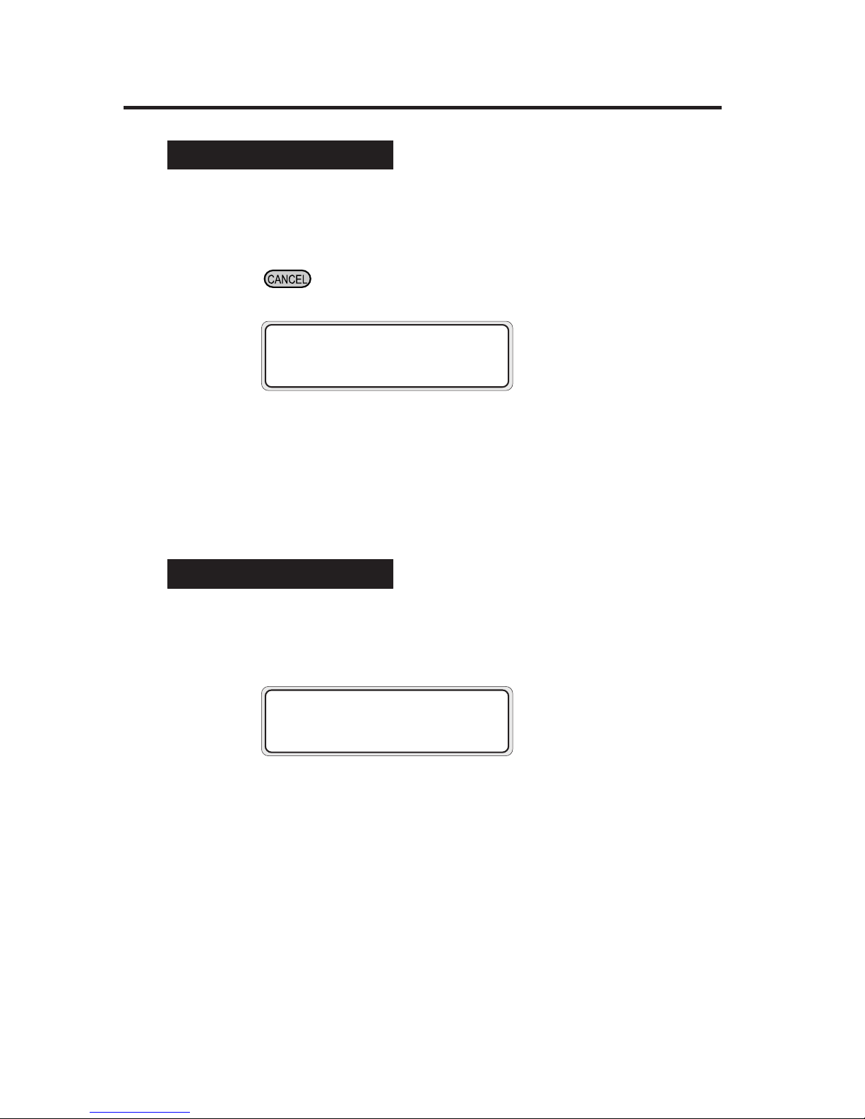
1 To turn the power OFF without fill cap operation,
simultaneously press the power ON/OFF switch and the
key on the operation panel continuously for 2 to 3
seconds.
The above message is displayed on the LCD to indicate that the
shutdown process is in progress. After the process ends, the power
is turned OFF.
Use this procedure to turn the power OFF to recover from an error
or communication disorder.
Turning the Power OFF 2
1 Turn the power ON/OFF switch on the operation panel
OFF for a couple of seconds.
The above message is displayed on the LCD to indicate that the
shutdown process is in progress. After the process ends, the power
is turned OFF.
At shutdown, fill cap operation (filling the cap with ink) is executed
to maintain the head in good condition.
*For restarting the printer within 20 hours
SHUTDOWN
WAIT A MOMENT
SHUTDOWN
WAIT A MOMENT
*When turning the printer OFF for 20 hours or more
Page 55

2-11
Section 2 Basic Operations
- The AC1 switch and AC2 switch on the rear of the printer
should be used only when the printer is turned OFF
completely in order to move it, connect it with a computer,
install or maintain its parts.
- When turning the power ON/OFF switch OFF, wait for at
least ten seconds, then turn it ON again.
- The printer automatically performs fill cap operation to
maintain good head condition after the first 20 hours in the
standby state and every 3 days thereafter.
It is recommended to keep the printer ON.
- The fill cap operation is effective for protecting the head,
but it consumes extra ink.
CAUTION
Turning the Power ON/OFF
Page 56
2-12
Installing/Removing the Media
The media can be fed to the printer in the following five ways:
- "MAIN" : Normal feed from the main scroller
- "SUB" : Feed from sub scroller
- "DUAL" : For dual roll printing
- "FACE or BACK" : For duplex printing (⇒ See Section 4)
- "SHEET" : Feed of cut sheet
This section explains MAIN, SUB, and CUT SHEET feeds.
Installing Main Scroller
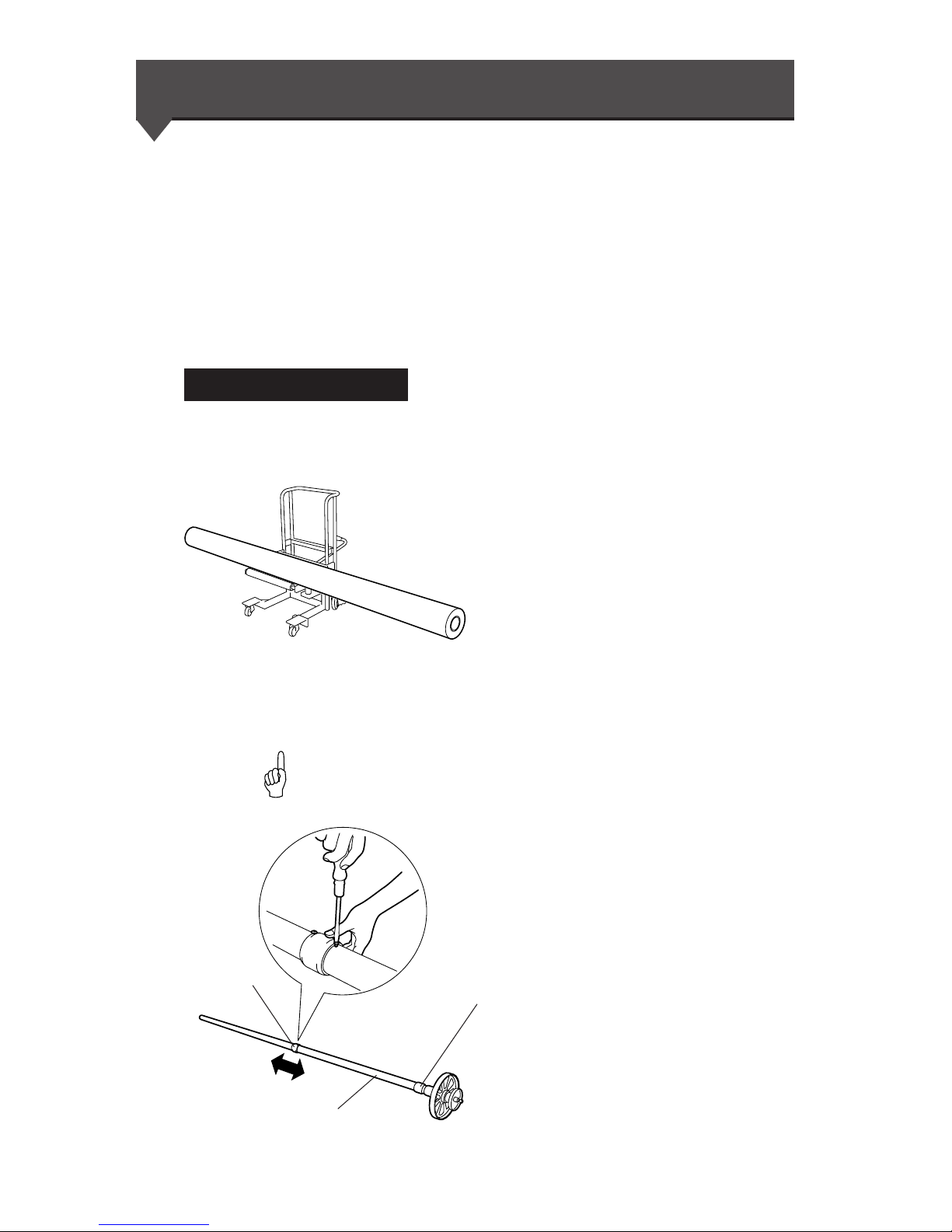
1 Place the media on the table.
If a cart is used, it should be the
recommended model. (For further
information, please contact us.)
2 Adjust the roll spacer position according to the media
width.
- The roll spacer prevents the paper tube from sagging in
the center by the weight of media.
(1) Remove the two screws, and move the roll
spacer so that it comes to the center of the
media. The spacer is locked at three places with
the screws.
Roller spacer
HINT
Do not move this roller spacer
Main scroller
Page 57
2-13
Section 2 Basic Operations
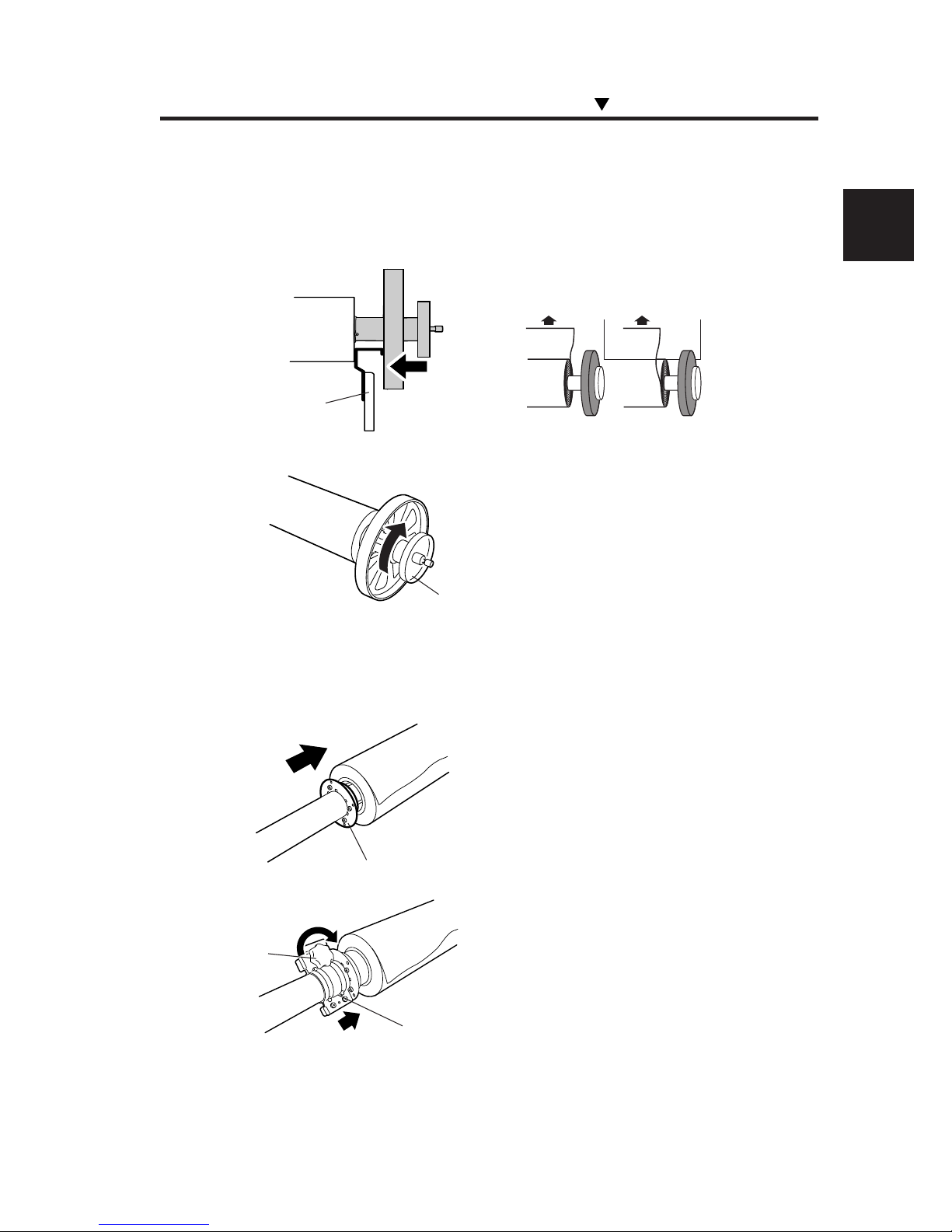
3 Pass the scroller through the paper tube, determine the
distance between the media edge and flange, and lock
the main scroller.
(1) Confirm the media winding direction, and
pass the scroller through the paper tube.
(2) Using the media positioning tool, determine
the distance between the media edge and flange.
(3) Rotate the handwheel clockwise until it
stops, then lock the main scroller.
4 Engage the flange spacer with the flange stopper, and
install them.
(1) Push in the toothed flange spacer until it
stops.
(2) Install the flange stopper by aligning it to the
hook of the flange spacer, then tighten the knob
to lock.
(3) Shift the tension bar guide to avoid
interference.
Outer take-up
Inner take-up
Handwheel
Flange stopper
Knob
Flange spacer
Media positioning
tool
Installing/Removing the Media
Page 58
2-14
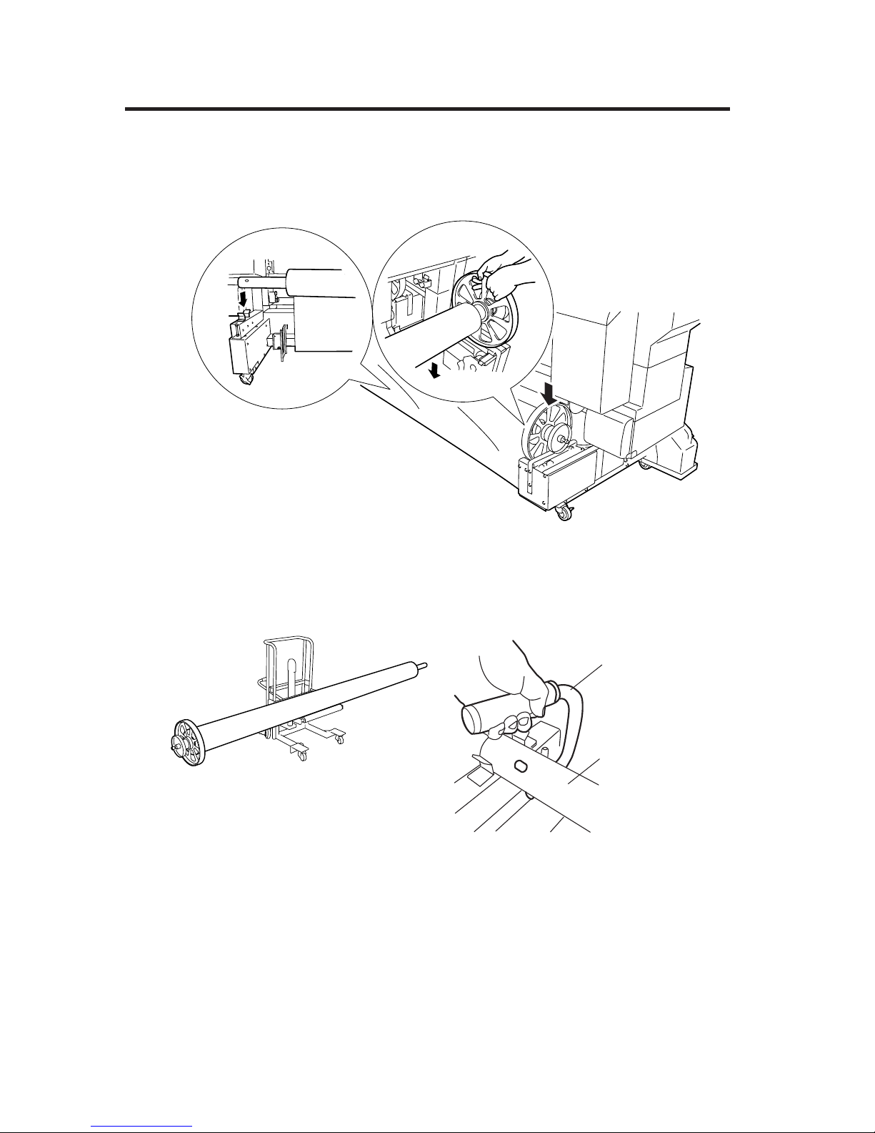
5 Fitting in the roll groove, install the main scroller on the
printer.
• For installation with one person:
Use the recommended cart.
• For installation with two persons by holding
the scroller by hand:
Use the attached scroller grip.
Scroller grip
Main scroller
Page 59
2-15
Section 2 Basic Operations
Media Setting
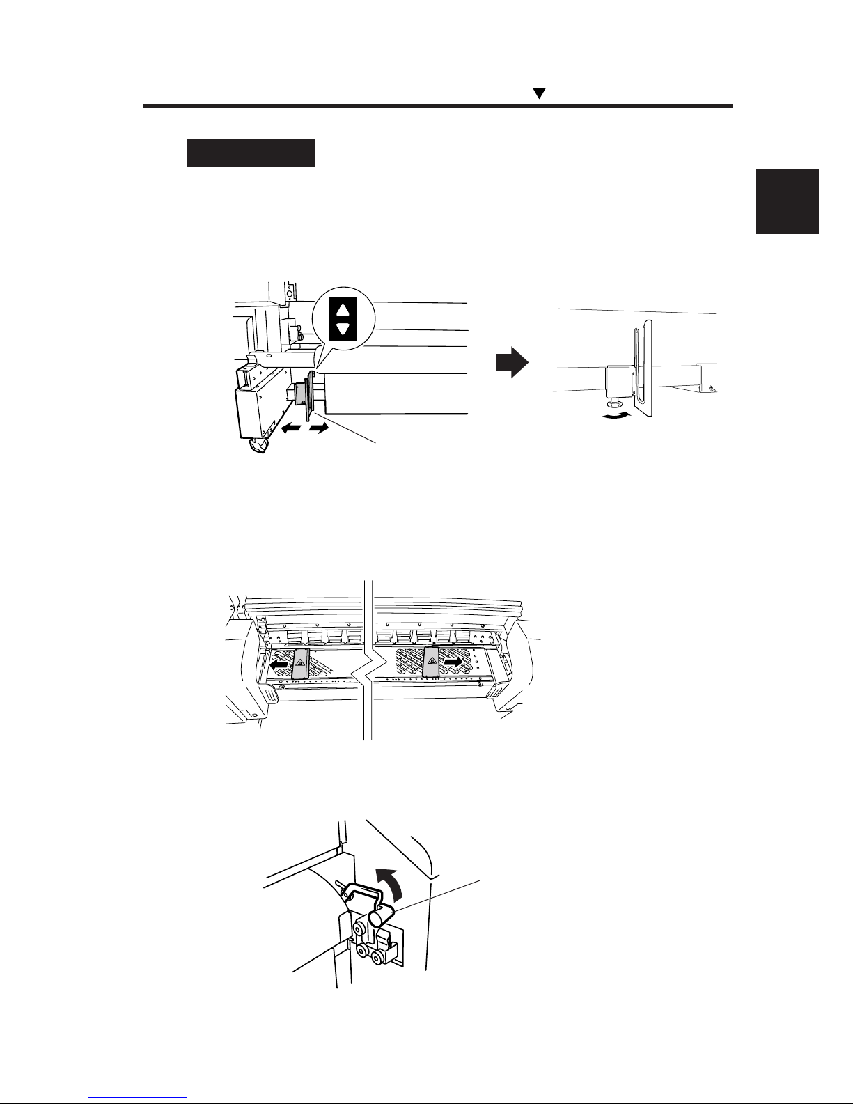
1 Move the tension bar guide to the position of the label,
then fix it in place with the screw below the guide.
2 Shift the media edge guards to both sides so that they
are not hidden under the media.
3 Lift the pressure roller up/down lever.
Installing/Removing the Media
Pressure roller up/
down lever
Tension bar guide
Page 60
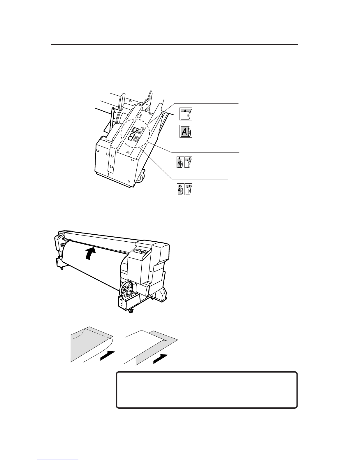
2-16
4 Set the feed direction switches.
5 Slacken the media using the Feed switch and insert the
media edge into the paper feeder.
(1) Insert the media into the paper feeder while
stretching the media with your hands to prevent
wrinkle.
If the media curls and is hard to insert into the
paper feeder, place a backing sheet on the curled
media and insert the media edge. (See the figure
at left.)
(2) Feed the media until its top edge is about to
reach the floor. At this time, smooth the media
toward both sides on the platen so that the
central area of the media is tensioned.
- Inserting the media obliquely or inserting wrinkled media
causes a paper jam or skewed feed.
Feed direction switch
Winder switch (white)
Feed switch (green)
■ Feed direction switch, Winder switch, Feed switch
Inner take-up
Outer take-up
Media
Media
• Up-curl • Down-curl
NOTE
Page 61
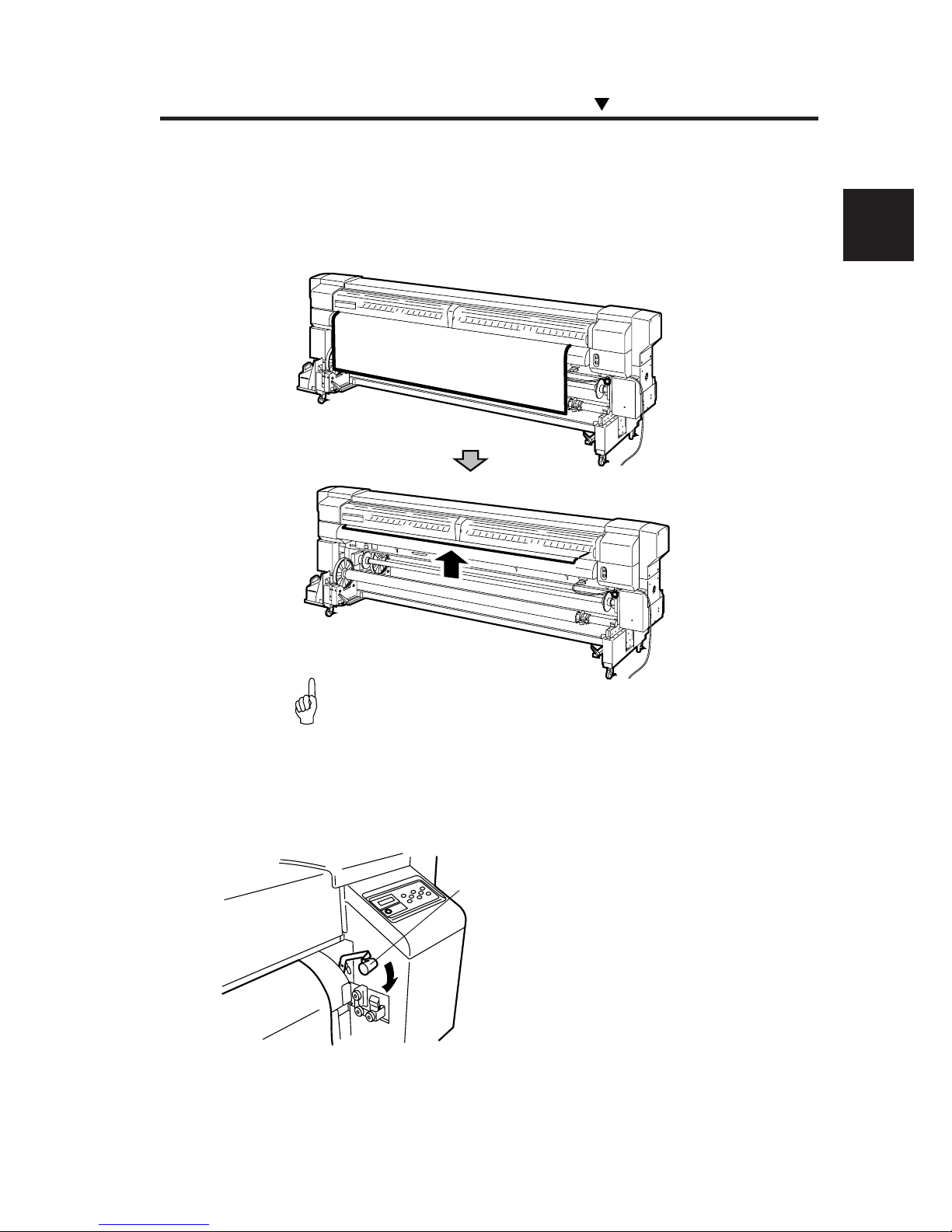
2-17
Section 2 Basic Operations
Installing/Removing the Media
6 Using the Winder switch on the feeder side, rewind the
media so that the media edge protrudes from the rear
cover a little.
-Work in step 6 is important for correct setting of the media.
7 Push the pressure roller up/down lever down.
Pressure roller up/
down lever
HINT
Page 62
2-18
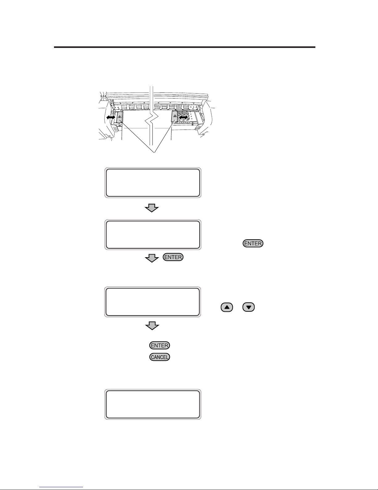
8 Set the media edge guard, and close the rear cover.
(1) Close the rear cover.
(2) Confirm the media edge guard position
and press the key, and the media
width checking operation will start.
9 Select the media feed position.
From the parameters, select "MAIN"
with or key.
Press the key to change the setting.
Press the
key to hold the last setting as it is.
10 Select the base function.
Select "USED" if the "Origin Point
Setting Function (⇒ See page 2-58)" is
used.
Media edge guard
MEDIA POSITION
SELECT: MAIN
CLOSE REAR COVER
CHECK EDGE GUARD
✽OK?
BASE FUNCTION
SELECT: NOT USED
Page 63
2-19
Section 2 Basic Operations
Press the key to enter the NEW PAPER ENTRY menu.
Operation for a new paper entry is the same as operation for media
entry from the ENTRY menu. (⇒ See Section 3, Entry Menu)
Press the key to return to the SELECT PAPERTYPE menu.
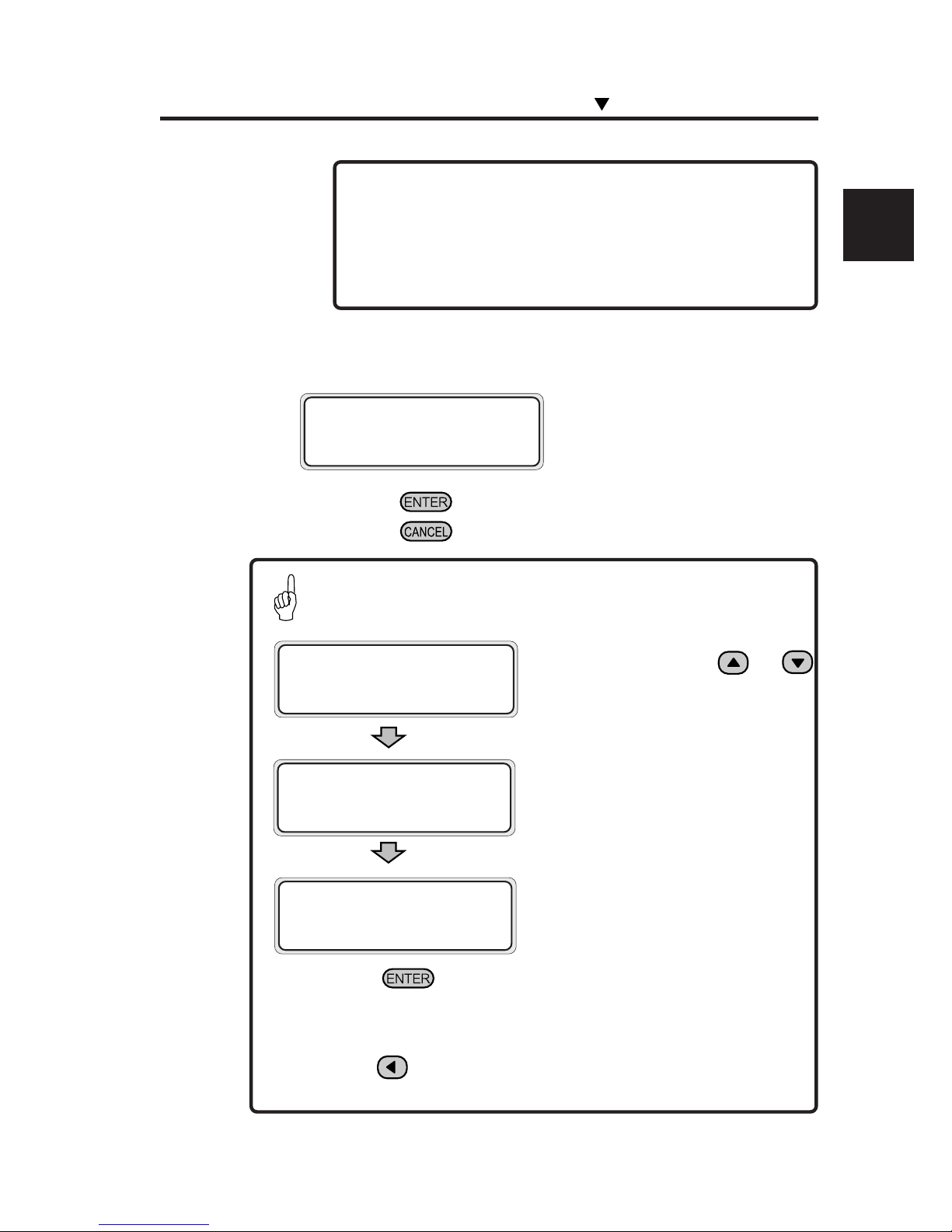
SELECT PAPERTYPE
PAPER : TYPE01
When registering a new media type
SELECT PAPERTYPE
NEW PAPER ENTRY
(Only registered media types can be
selected.)
- The base function selecting menu may not be displayed
depending on the version of the firmware. To use the base
function, select "SELECT: MAIN B" for the media feed
selection.
11
Select the media type.
Press the key to change the setting.
Press the
key to leave the setting as it is.
SELECT PAPERTYPE
PAPER : PAPER
Select a media type with the and
keys.
SELECT PAPERTYPE
PAPER : PAPER
Installing/Removing the Media
HINT
NOTE
Page 64
2-20
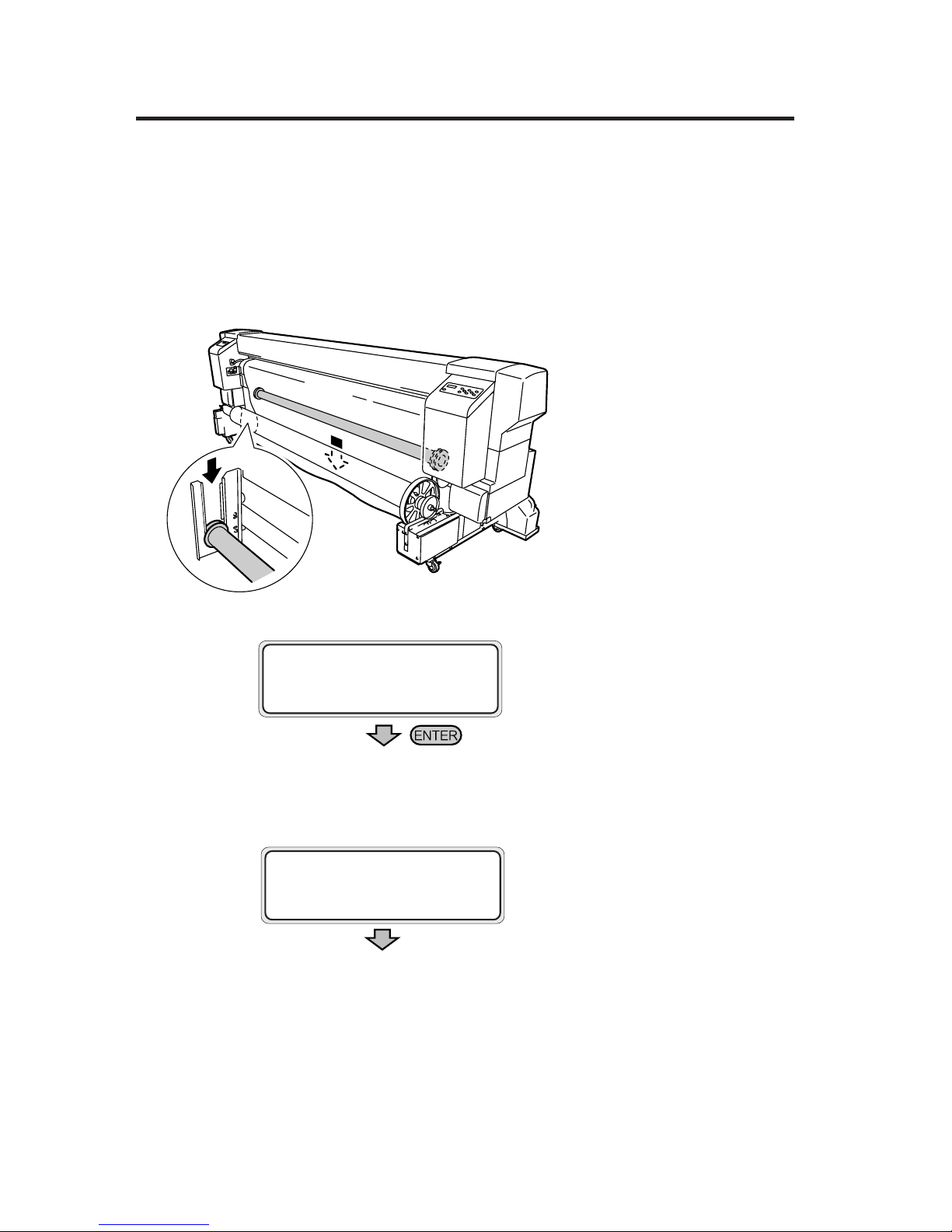
12 Using the feed switch on the feeder side, slacken the
media and install the tension bar.
Adjust the tension bar length according to the
media width. (See page 2-53, Tension Bar
Length Adjustment.)
• This message is skipped if cut media is
used.
• The next operation will not start if the
media slack is inadequate.
13 Media setting operation will start automatically.
• If the operation terminates normally,
the printer returns to the online or offline
state.
• If it terminates unsuccessfully, an error
message will be displayed.
Go back to step 5.
CHECK BUFFER
✽OK?
PREPARING PAPER
WAIT A MOMENT
Page 65
2-21
Section 2 Basic Operations
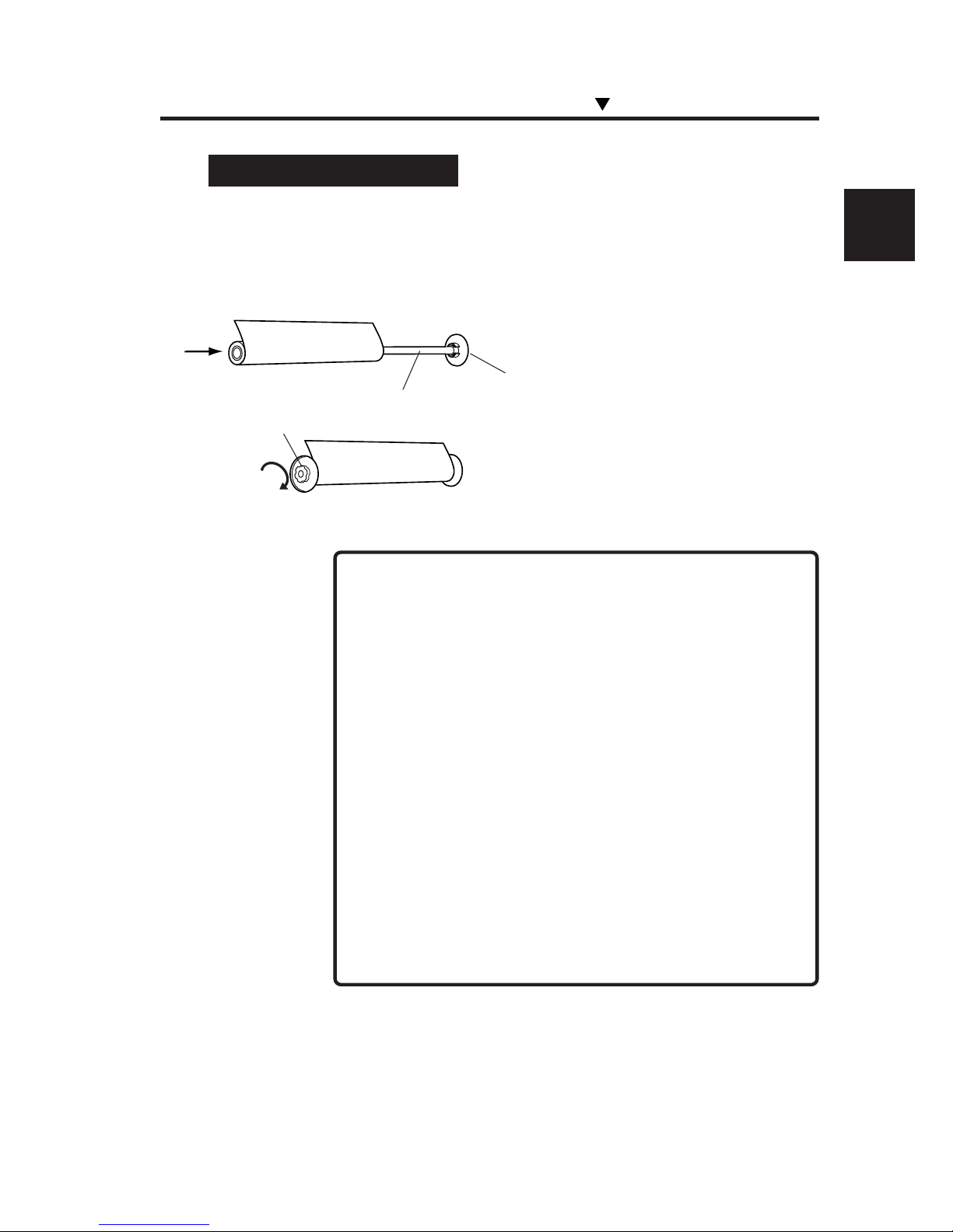
Installing the Sub Scroller
1 Install the media on the sub scroller.
(1) Confirming the media for inner take-up or
outer take-up, insert it into the sub scroller.
(2) Lock the left flange tightly.
-Take care not to damage the media edge when inserting
the media.
- Place the media on the table when installing or removing
the media. Holding the media erect causes the media
winding to come loose, thereby skewed feed.
- Before installing the media, clean the print surface and
sides of the media.
- Specifications of media
Diameter: 165 mm
Weight: 24 kg (When dual roll kit is used)
- When heavy media is fed to the sub scroller, the shaft
becomes bent, causing degrading of print quality and
skewing. When it is desired to use heavy media with the
sub scroller, use the optional dual roll kit. It can handle
media up to 24 kg.
Installing/Removing the Media
Sub scroller
Right flange is secured to the
scroller
Left flange
(Outer take-up)
NOTES
Page 66
2-22
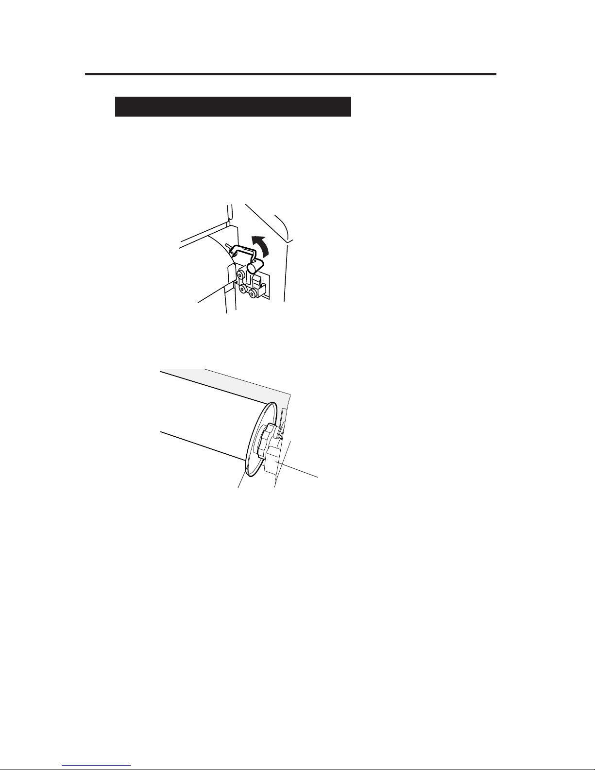
Installing the Sub Scroller on the Printer
1 Shift the media edge guards toward both sides.
2 Lift the pressure roller up/down lever.
3 Place the sub scroller on the sub scroller holder.
4 Insert the media into the feeder, and feed the media until
its top edge is about to reach the floor.
Sub scroller
Sub scroller holder
Page 67
2-23
Section 2 Basic Operations
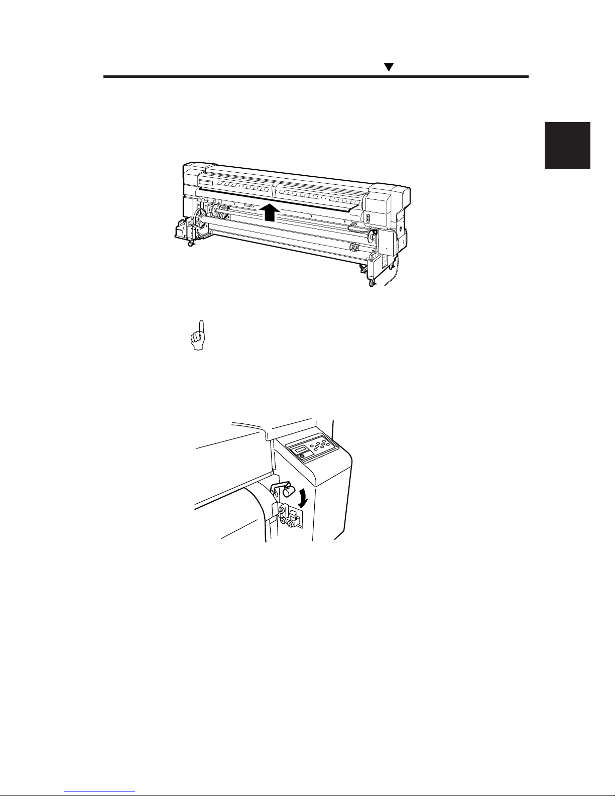
5 Rotating the sub scroller by hand, rewind the media so
that the media edge protrudes from the rear cover a little.
- Restrain the central area of the media by hand to elimi-
nate slack in the media.
6 Push the pressure roller up/down lever down.
7 Set the media edge guards, and close the rear cover.
Installing/Removing the Media
HINT
Page 68
2-24
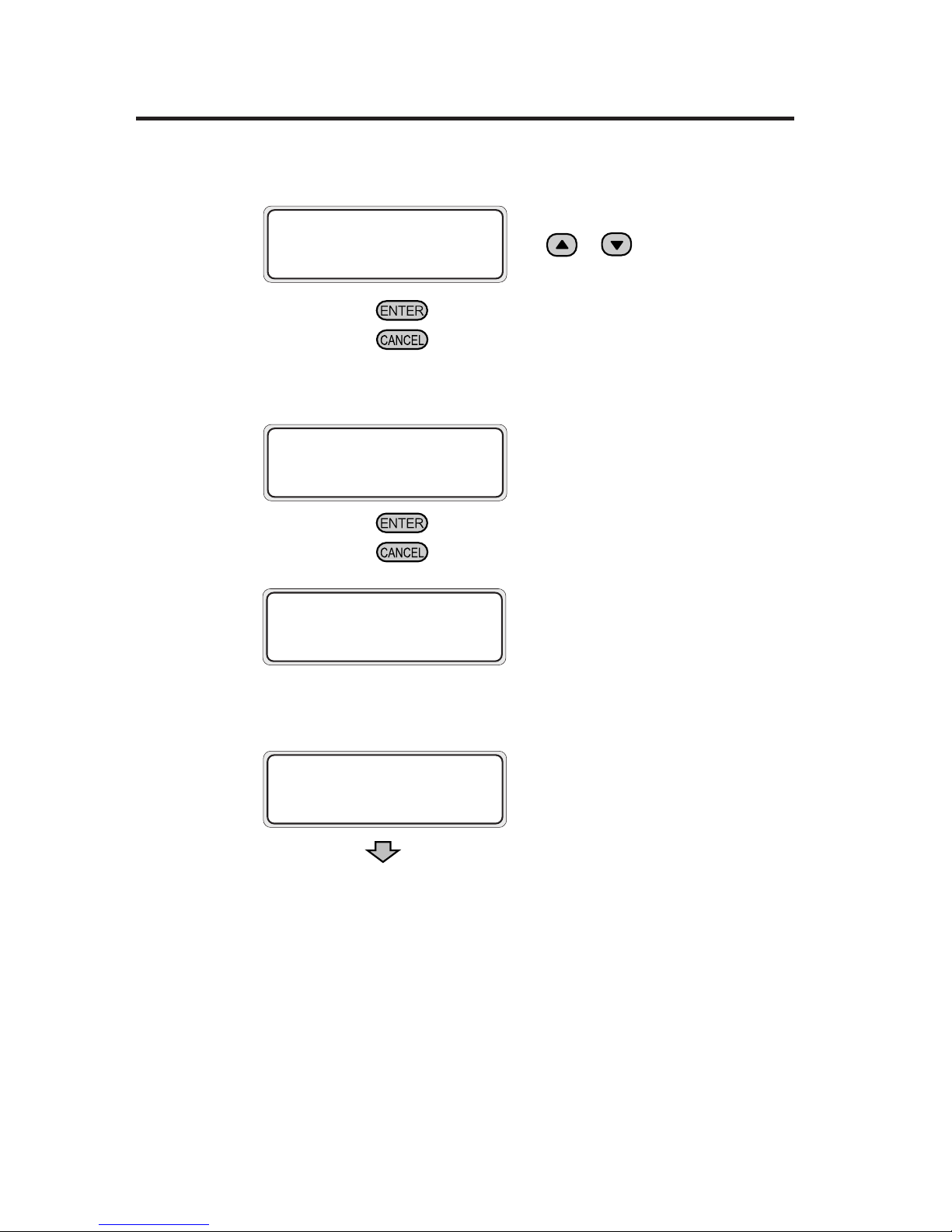
8 Select the media feed.
From the parameters, select "SUB" with
the
or key.
Press the key to change the setting.
Press the key to hold the last setting as it is.
9 Select the media type.
Press the key to change the setting.
Press the
key to hold the last setting as it is.
Select "USED" if the "Origin Point
Setting Function (⇒ See page 2-58)" is
used.
10 Media setting operation will start automatically.
• If operation terminates normally, the
printer returns to the online or offline
state.
• If it terminates unsuccessfully, an error
message will be displayed.
Return to step 4 for retry.
BASE FUNCTION
SELECT: NOT USED
MEDIA POSITION
SELECT SUB
SELECT PAPER TYPE
PAPER: PAPER
PREPARING PAPER
WAIT A MOMENT
Page 69
2-25
Section 2 Basic Operations
Installing/Removing the Media
Installing or Removing the Cut Sheet
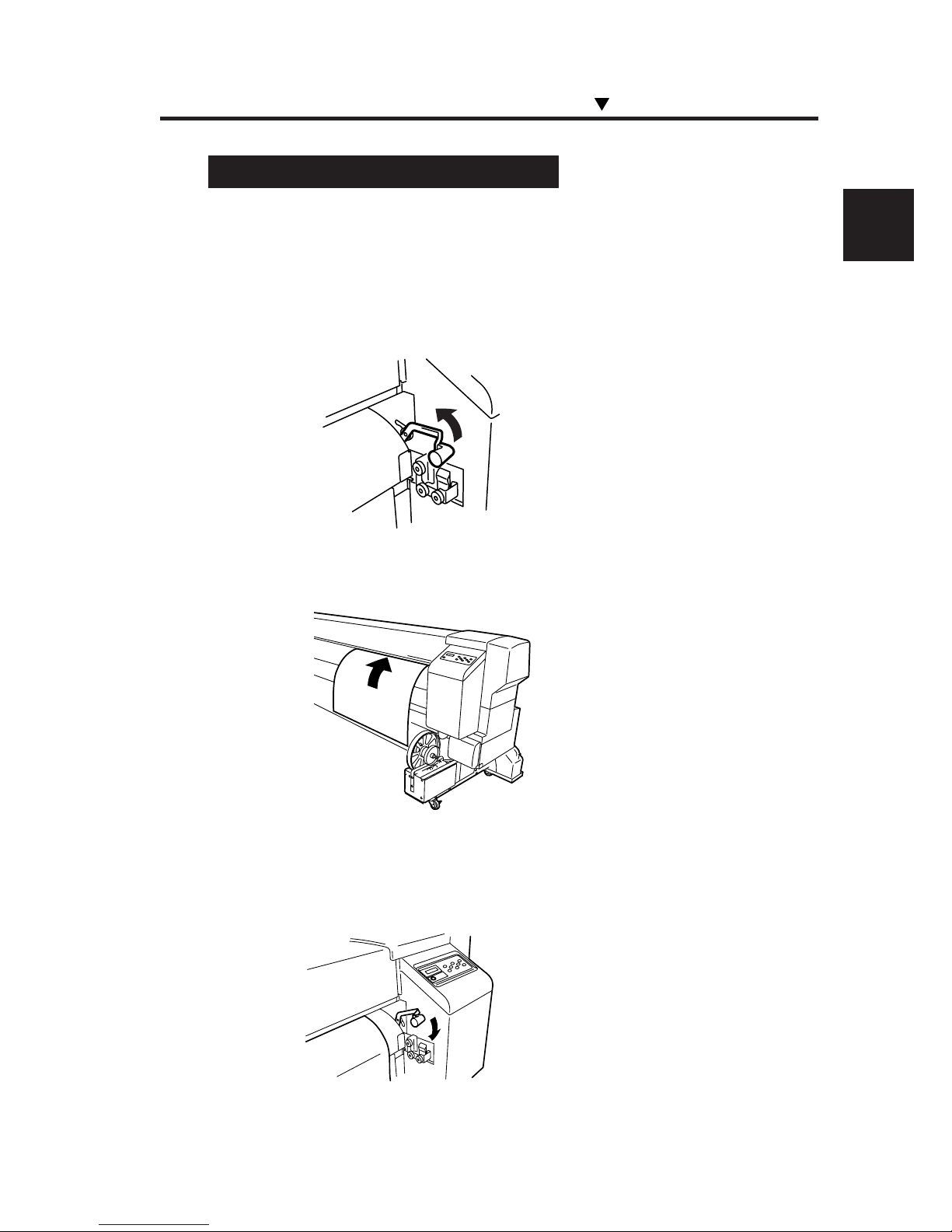
1 Shift the media edge guards toward both sides.
2 Lift the pressure roller up/down lever.
3 Aligning the right edge of a cut sheet with the guideline,
insert the cut sheet into the paper feeder.
4 Set the media edge guards, and close the rear cover.
5 Push the pressure roller up/down lever down.
Page 70
2-26
6 Select the media feed.
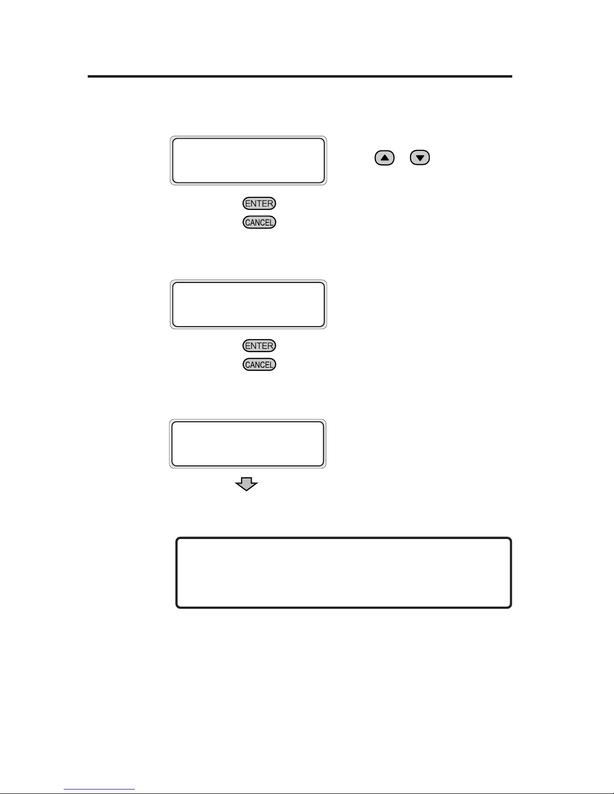
From the parameters, select "SHEET"
with the
or key.
Press the key to change the setting.
Press the key to hold the last setting as it is.
7 Select the media type.
Press the key to change the setting.
Press the
key to hold the last setting as it is.
8 Media setting operation will start automatically.
• If the operation terminates normally,
the printer returns to the online or offline
state.
• If it terminates unsuccessfully, an error
message will be displayed.
Return to step 1 for retry.
To remove the cut sheet, lift the pressure roller up/down lever
and remove it.
MEDIA POSITION
SELECT: SHEET
SELECT PAPERTYPE
PAPER: PAPER
PREPARING PAPER
WAIT A MOMENT
REMOVE
Page 71
2-27
Section 2 Basic Operations
Installing/Removing the Media
Installing the Media Roll in the Winder
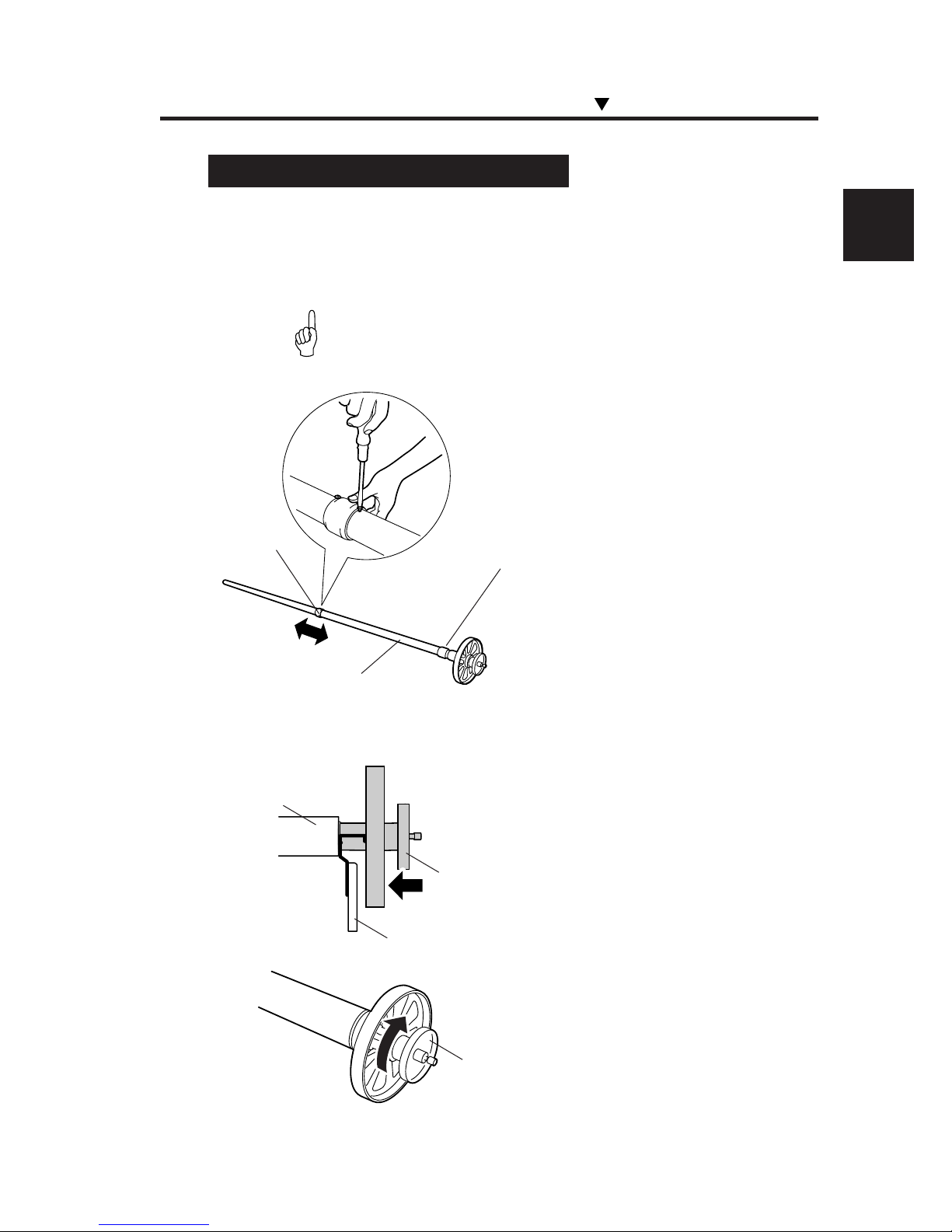
1 Adjust the roll spacer position according to the media
width.
- The roll spacer prevents the paper tube from sagging in
the center by the weight of media.
(1) Remove the two screws, and move the roll
spacer so that it comes to the center of the
media. The spacer is locked at three places with
screws.
2 Prepare the paper tube, and insert it into the scroller.
(1) Using the media positioning tool, determine
the distance between the edge of the paper tube
and the flange, and rotate the handwheel to lock
the main scroller.
HINT
Roller spacer
Main scroller
Do not move this roller spacer
Media positioning tool
Paper tube
Main scroller
Handwheel
Page 72
2-28
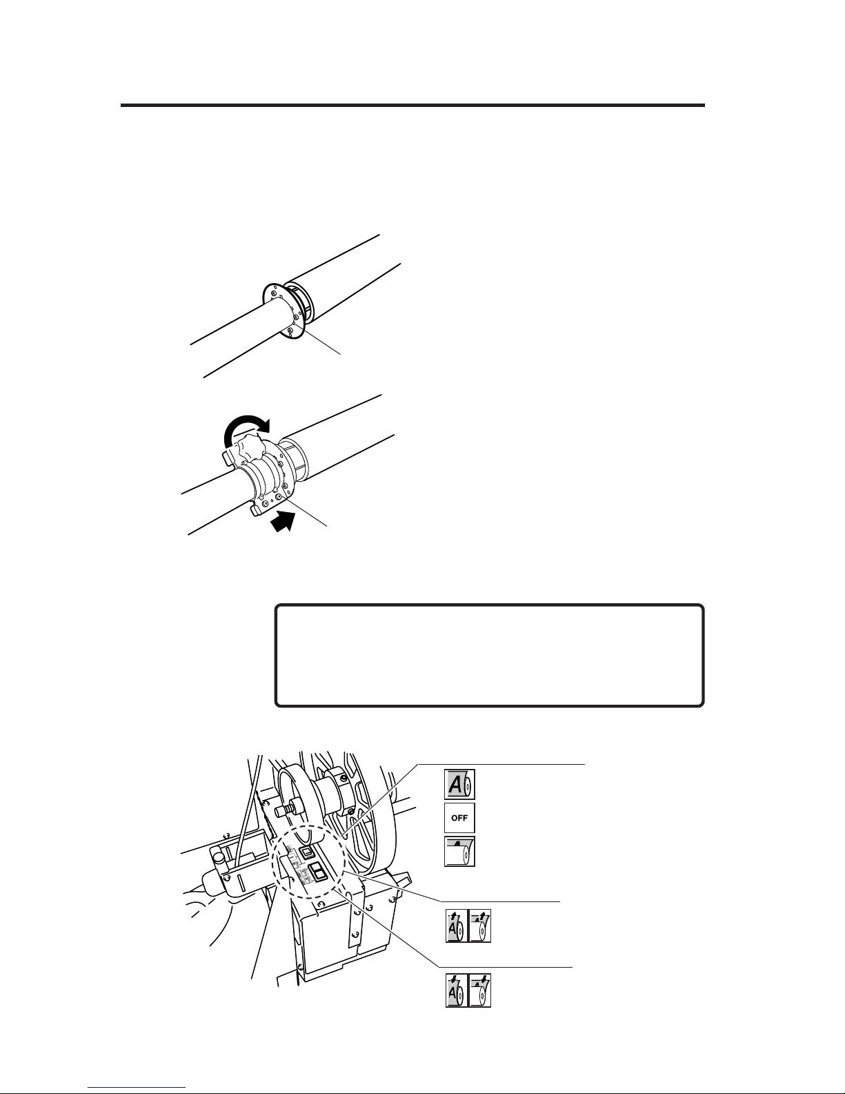
3 Engage the flange spacer with the flange stopper, then
install them.
(1) Push in the toothed flange spacer until it
stops.
(2) Install the flange stopper by aligning it to the
hook of the flange spacer, then tighten the knob
to lock.
4 Set the take-up direction switch to the "OFF" position.
- If you proceed to the next step without setting the take-up
direction switch to the "OFF" position, the scroller is not
locked, thus causing your hand to be caught.
Flange spacer
Flange stopper
■ Take-up direction switch, Winder switch, and Feed switch
Take-up direction switch
Feed switch (white)
Winder switch (green)
Outer take-up
· OFF
Inner take-up
NOTE
Page 73
2-29
Section 2 Basic Operations
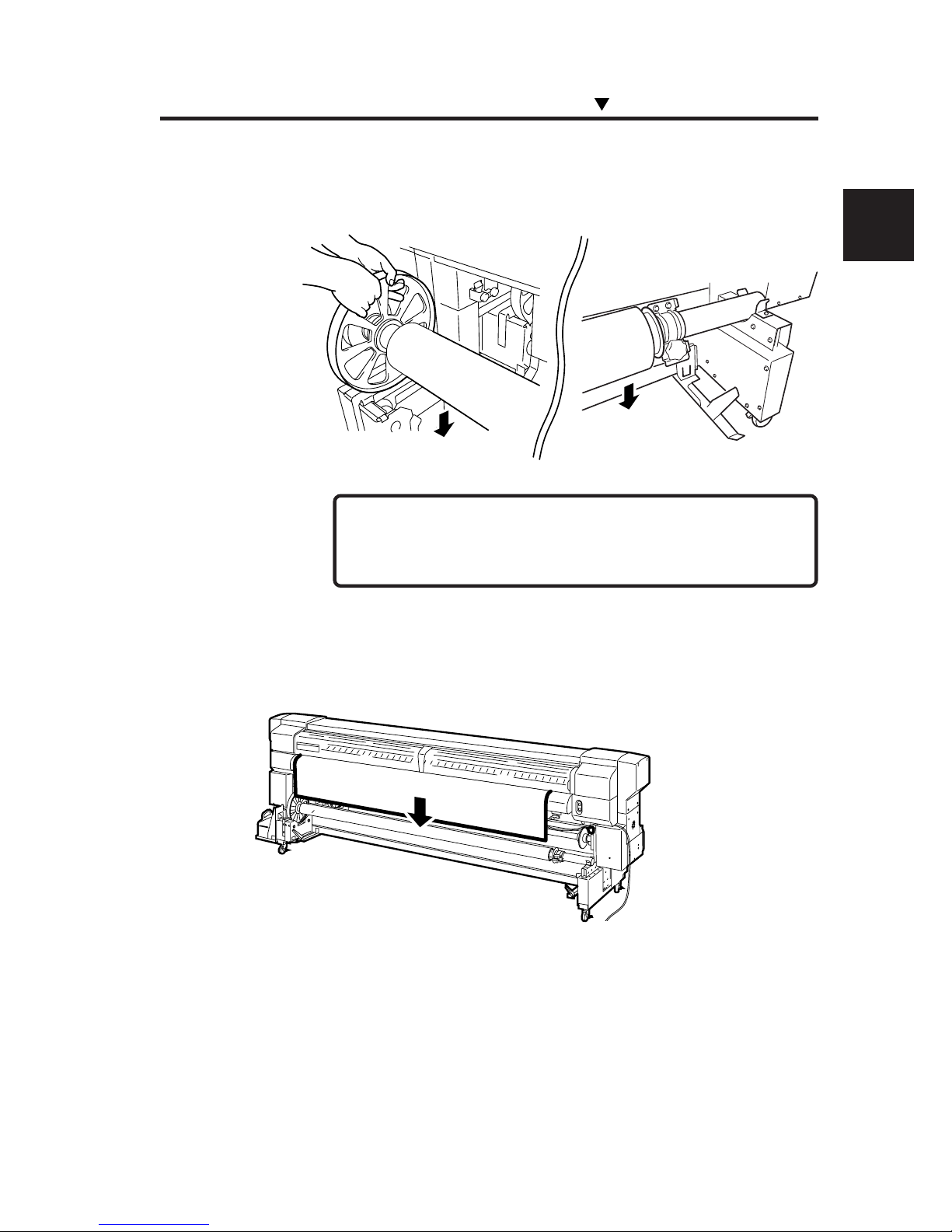
5 Fitting in the roll groove of the printer, install the main
scroller.
- Engage the tension bar with the tension bar hook in
advance.
6 Using the feed menu on the operation panel, feed the
media to the extent that the media can be wound.
Installing/Removing the Media
NOTE
Page 74
2-30
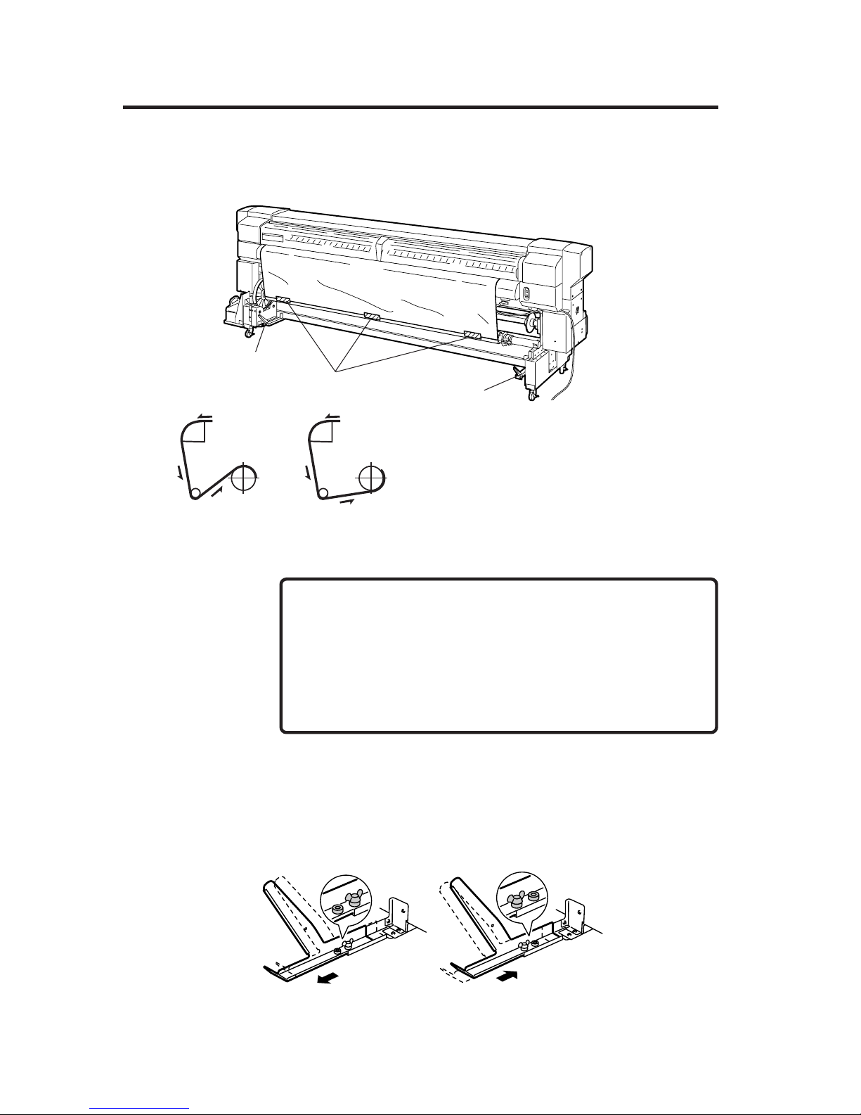
7 Secure the fed media to the paper tube.
(1) Confirm the take-up direction, and secure
the media with adhesive tapes at three places;
first secure the center so that it is straight, and
then secure both sides.
- Make sure that the direction of the attaching tape on the
take-up side matches the take-up direction setting (outer
side rewind/ inner side rewind).
- If the media is attached to the paper tube at an angle it will
be fed at an angle, so use caution.
8 Adjust the tension bar guide position according to the
take-up direction.
Outer take-up :
Paper is wound so that the
print surface comes inside.
Inner take-up :
Paper is wound so that the
print surface comes outside.
Tapes
Tension bar guide
Tension bar guide
■ Inner take-up
■ Outer take-up
NOTES
Page 75
2-31
Section 2 Basic Operations
Installing/Removing the Media
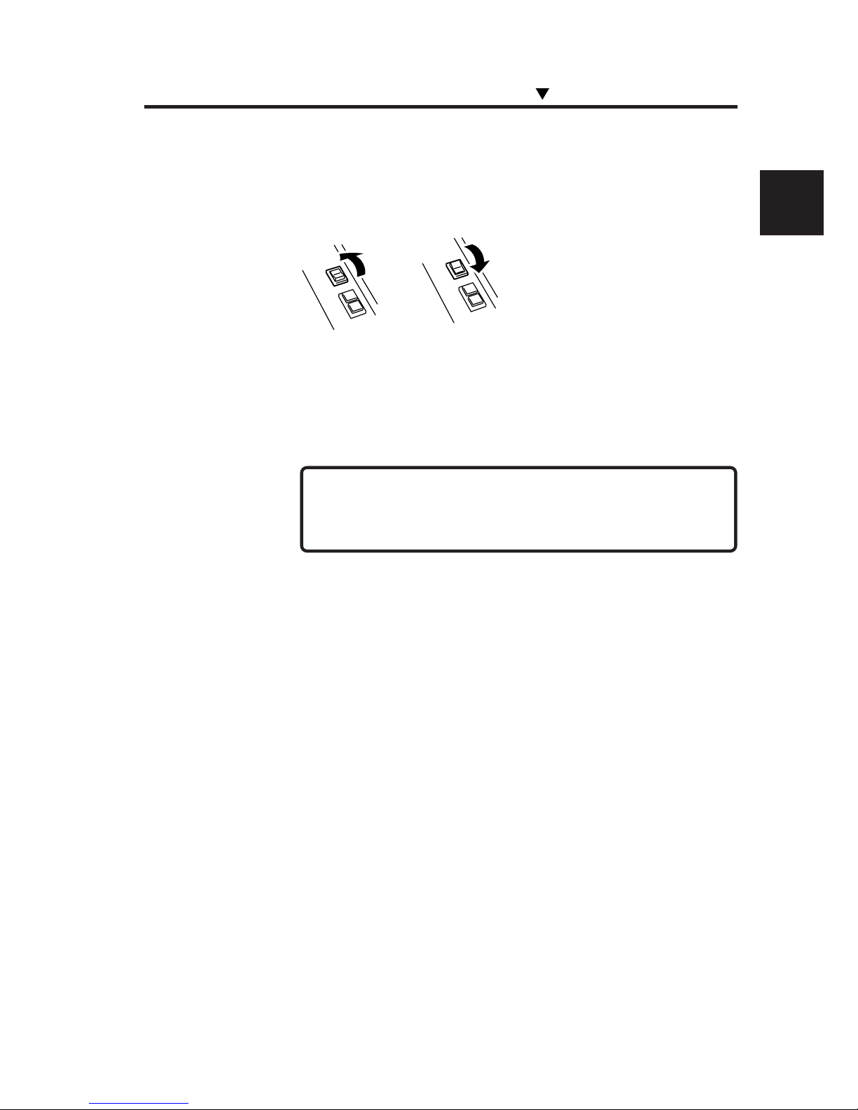
9 Press the take-up direction switch according to the take-
up direction.
10 Using the feed menu on the operation panel, feed the
media to wind it on the paper tube by one turn. Then, set
the winding direction switch in the "OFF" position.
- Installing the tension bar without winding the media by one
turn causes the tapes to be peeled off.
11 Using the feed menu on the operation panel, feed the
media to the extent (about 30 cm) that slack appears.
■ Outer take-up
■ Inner take-up
NOTE
Page 76
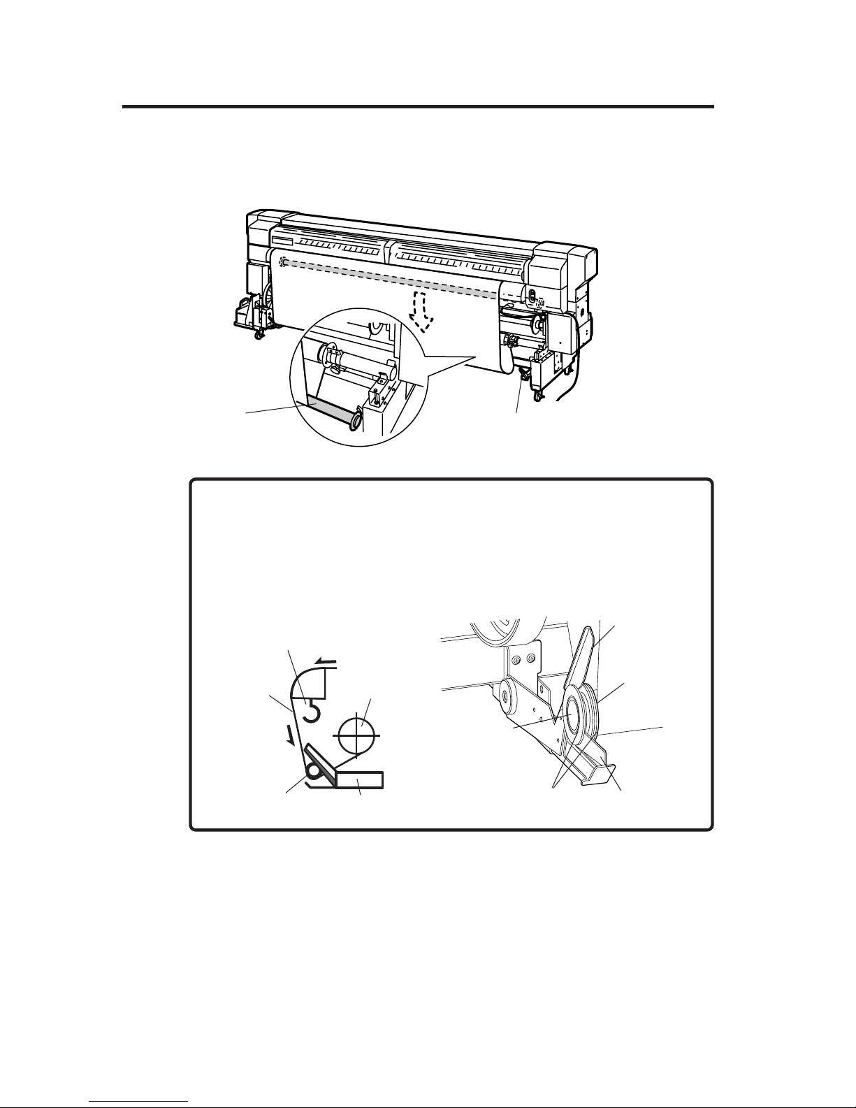
2-32
12 Install the tension bar in a slack part of the media.
Tension bar guide
Tension bar
- Attach the tension bar so that it is gripped between the tension bar
guide and the sensor arm.
- Adjust the guide position so that the tension bar guide is gripped
between the 2 flanges.
NOTE
Tension bar guide
Tension bar
Main scrollerMedia
Tension bar hook
Tension bar
guide
Tension bar
Flange
Sensor arm
Flange for
take-up
Page 77
2-33
Section 2 Basic Operations
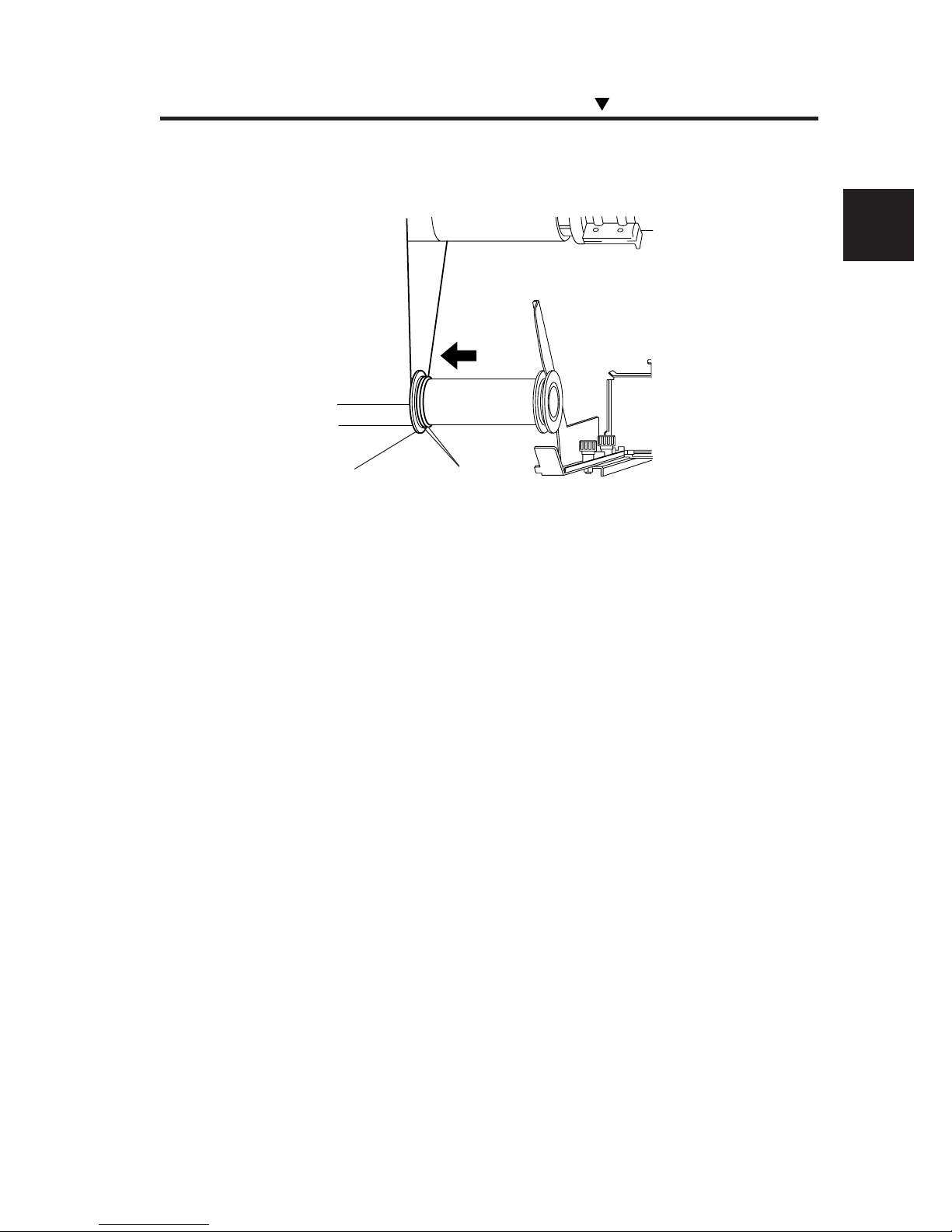
13 Move the flange according to the media width.
14 Press the take-up direction switch according to the take-
up direction.
Installing/Removing the Media
Fixing rings
Flange for take-up
Page 78
2-34
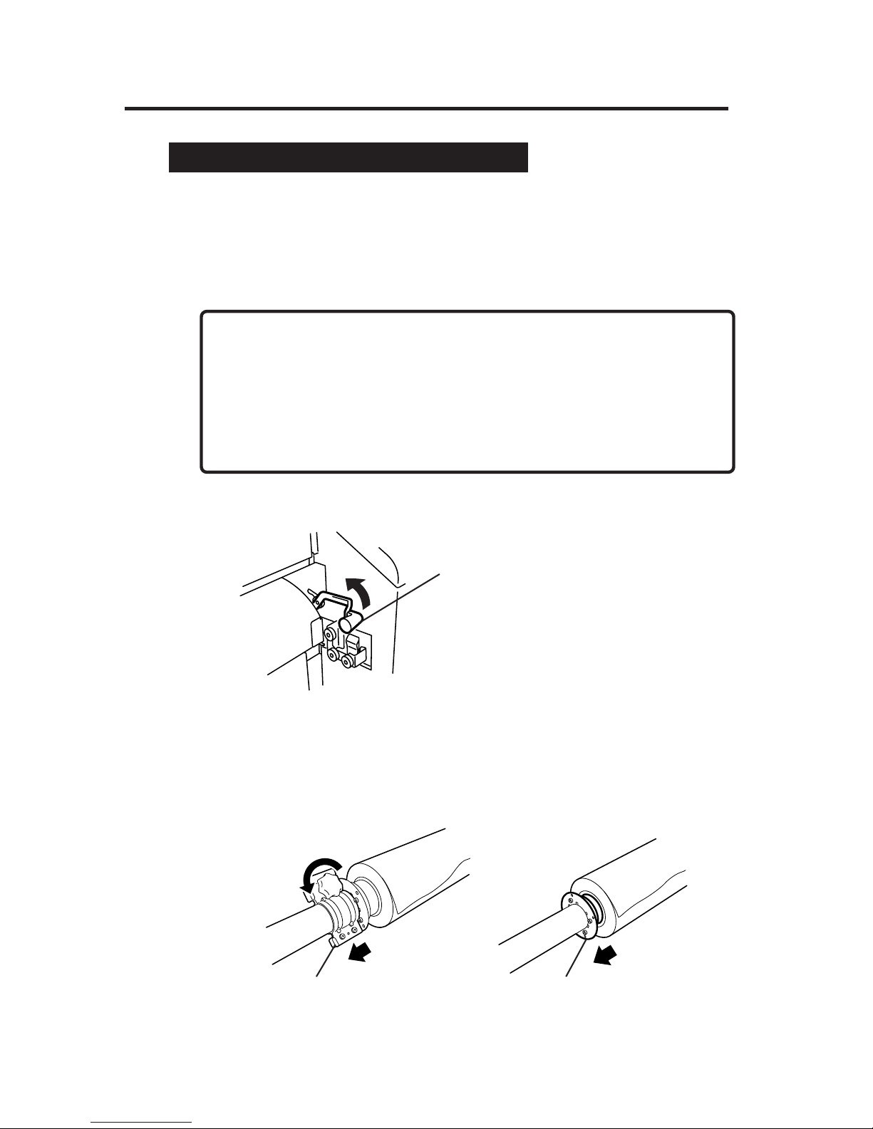
Removing the Paper Roll from the Printer
1 Remove the tension bars on the media feed side and
outlet side.
2 Cut the media.
3 Lift the pressure roller up/down lever.
4 Using the winder switch on the feed side, wind the media.
5 Place the media roll on the table.
6 Remove the flange stopper and the flange spacer.
Pressure roller up/down lever
Flange stopper
Flange spacer
-A net is spread out on the feeding side and take-up side paper guides,
respectively so that the media will not adhere to the guides. Do not
remove these nets.
- When cutting the media, be careful not to damage the paper guide
net.
NOTES
Page 79
2-35
Section 2 Basic Operations
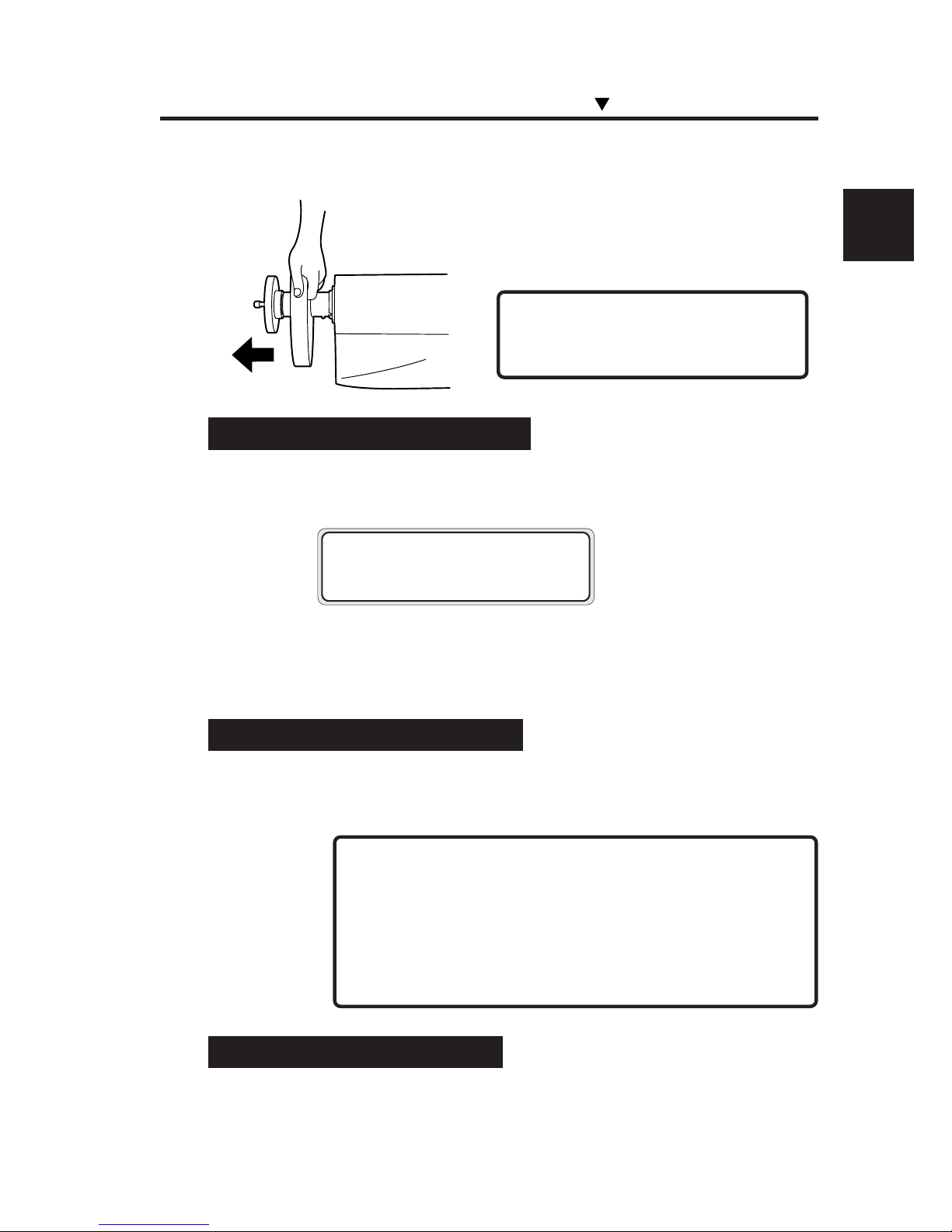
7 Remove the scroller.
(1) Rotate the handwheel counterclockwise.
(2) When a gap appears between the handwheel
and scroller shaft, remove the scroller.
- Do not touch the scroller hook.
NOTE
Replacing Media on Main Scroller
1 The following message appears on the LCD screen.
2 Replace the media following "Installing/Removing the
Media."
Replacing Media on Sub Scroller
1 The following message appears on the LCD screen.
- If the bottom edge of the media on the sub scroller has
been secured with tapes, the media end is detected with a
jam error. In this case, cleaning is not executed.
- If the media is not secured with tapes, the media end is
detected by the feed sensor.
Replacing Jammed Media Roll
See “Clearing Media Jam” in Section 6, Troubleshooting.
LIFT LEVER
SET PAPER
NOTES
Installing/Removing the Media
Page 80
2-36
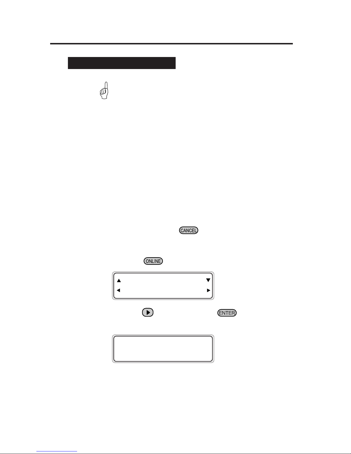
2 Set the printer to OFFLINE mode.
(Press the key)
3 Press the key, and then the key to display a
feed adjustment pattern.
#FEED PATTERN
✽ROUGH (NORMAL)
Select the print mode you usually use for the media to which the feed
correction value is set.
For details of the print modes, see page 4-2 "Print Modes".
INK ENTRY
PAPER F. ADJ
Feed Correction Value Setting
The feed correction value is changed by the following causes:
• Backing sheet is used/not used
• Print mode is changed
• Pressure is changed by the media pressure alternation
lever
• Winder is used/not used
• Media type
• Media feed path is different
• Feed mode "SEQUENCE 1" or "SEQUENCE 2"
1 Set media of length longer than 1 m.
For the feed correction, obtain approximate feed correction value in the
ROUGH mode, and set exact correction value in the DETAIL mode. One
printing requires a media length of 48 to 58 cm in the ROUGH mode, or 27
to 32 cm in the DETAIL mode. (Printing of the feed adjustment pattern can
be cancelled by pressing the key.)
HINT
Page 81
2-37
Section 2 Basic Operations
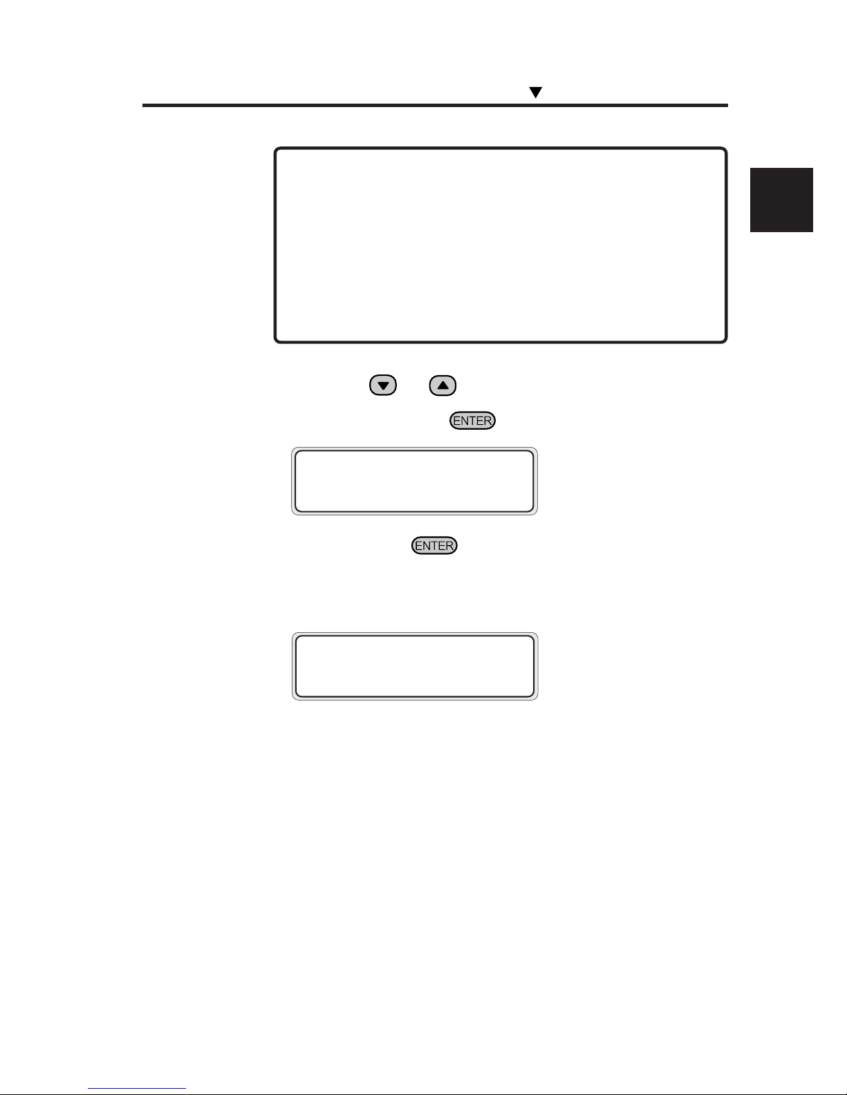
5 If you press the key, the feed adjustment pattern
"ROUGH" is printed.
The feed adjustment pattern "ROUGH" is printed in the selected print
mode.
#FEED PATTERN
✽EXECUTING
#FEED PATTERN
✽OK?
4 Press the or key to select the ROUGH print
mode, and press the key.
- Change the mode if the following setting is used:
FAST, FINE DRAFT → NORMAL
F-H-QUALITY → H-QUALITY
F-H-DENSITY → H-DENSITY
F-H-QUAL2 → H-QUALITY2
F-H-DENS2 → H-DENSITY2
F-3 TIMES → 3 TIMES
NOTE
Installing/Removing the Media
Page 82
2-38
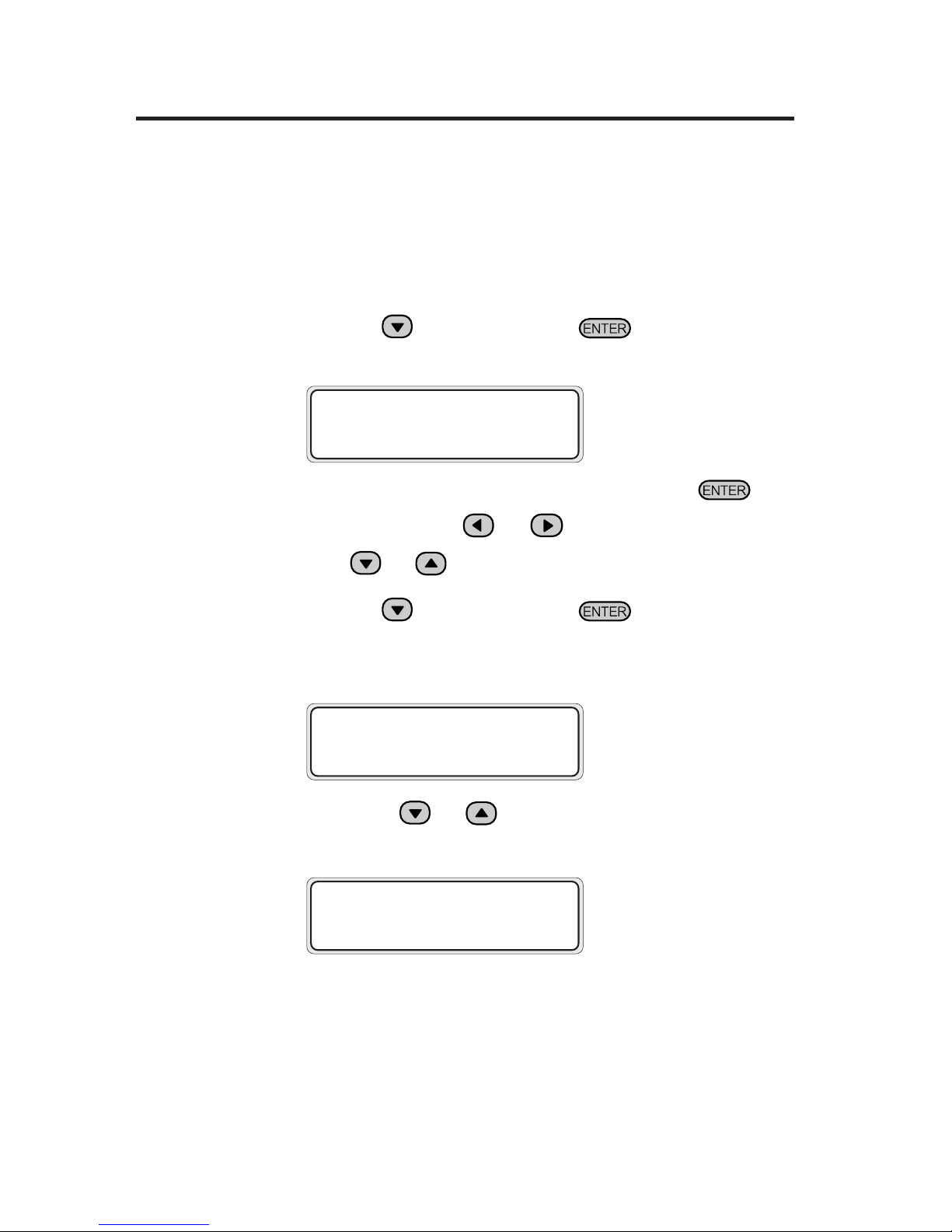
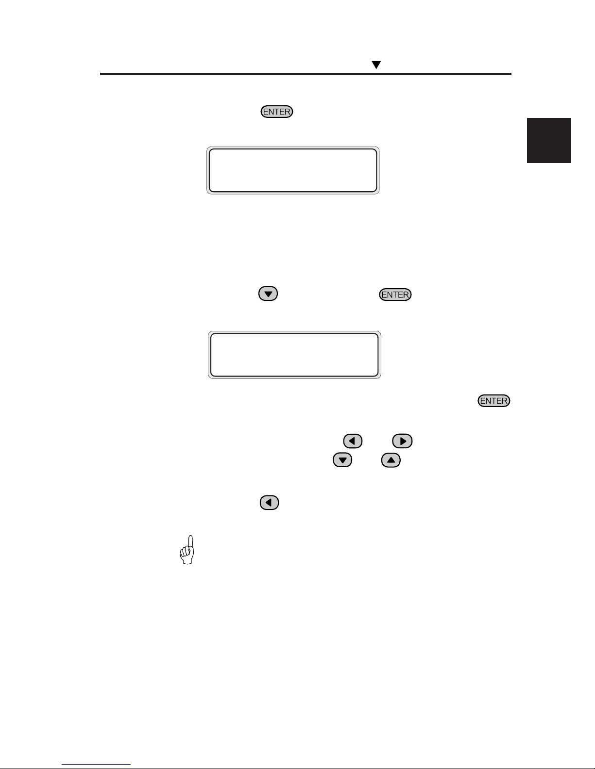
7 Press the key, and then the key to display the
feed correction value entry screen.
#FEED ADJUST
✽100.00%
8 Enter the feed correction value, and press the key.
Adjust the place with the and keys and enter the numeric value
with the and keys.
9 Press the key, and then the key to display the
feed adjustment pattern.
#FEED PATTERN
✽ROUGH (NORMAL)
10 Press the or key to select the DETAIL print
mode.
Select the same pattern as that for ROUGH.
#FEED PATTERN
✽DETAIL (NORMAL)
6 From the printed result, select the approximate feed
correction value.
Nine patterns are printed in steps of 0.25% in the range of 99.00% to
101.00%. Select the approximate correction value.
Page 83
2-39
Section 2 Basic Operations
13 Press the key, and then the key to display the
feed correction value entry screen.
#FEED ADJUST
✽100.00%
14 Enter the feed correction value, and press the
key.
Adjust the place with the and keys, and set the
numeric value with the and keys.
15 Press the key to return to the initial OFFLINE state.
-To change the feed correction value during the printing,
see page 3-6.
11 Press the key twice to print the feed adjustment
pattern "DETAIL".
#FEED PATTERN
✽EXECUTING
12 From the printed result, select the exact feed correction
value.
Five patterns are printed for the entered correction value in steps of 0.06%
in the range of -0.12% to +0.12%. Select the appropriate correction value.
HINT
Installing/Removing the Media
Page 84
2-40
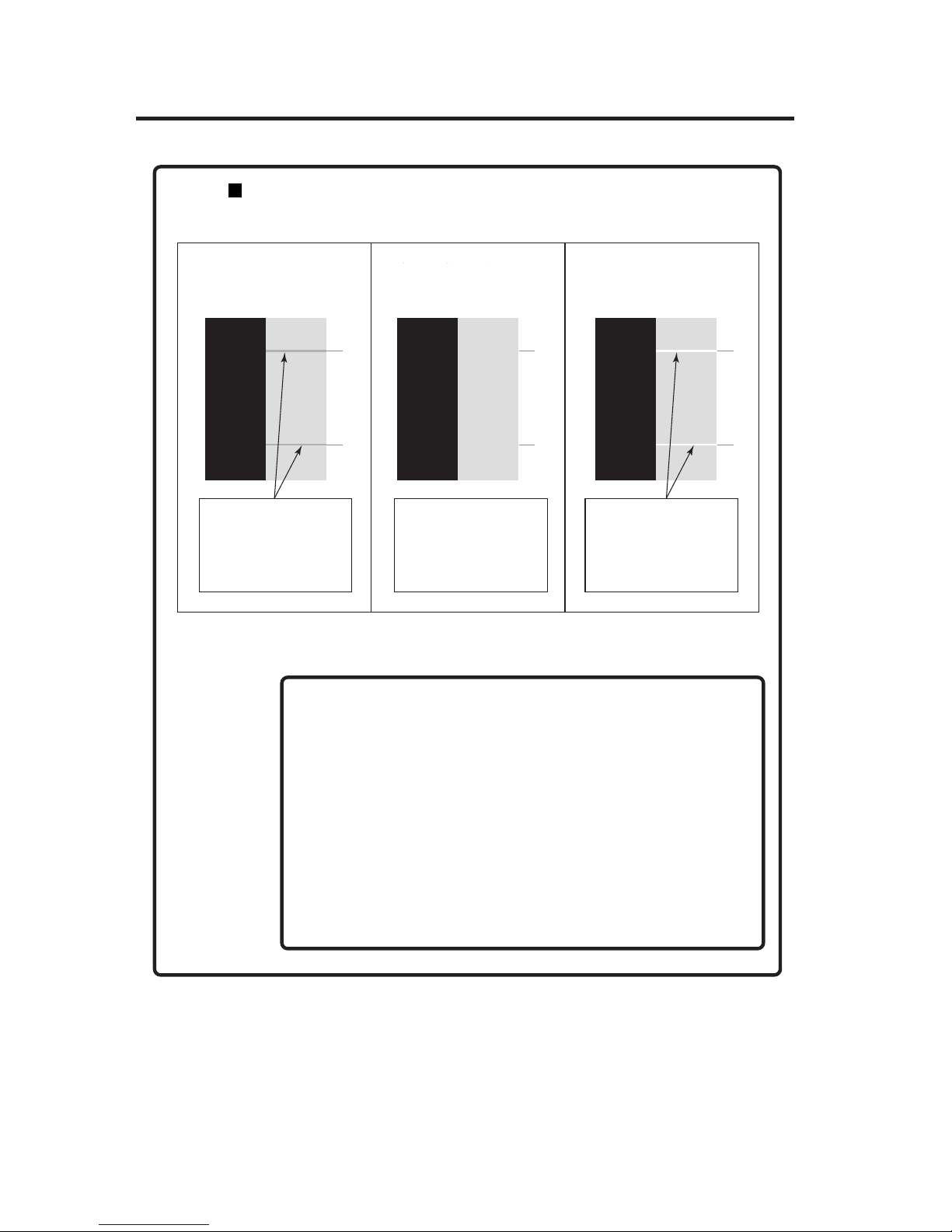
How to identify feed adjustment pattern
This description is for the case of black color.
If paper feed adjustment
correction value is small
If paper feed adjustment
correction value is appropriate
If paper feed adjustment
correction value is large
99.00% 100.25% 101.00%
Correction value is small
if the joints of pass lines
are overlapped (become
dark) on these
horizontal lines.
Correction value is
appropriate if the joints
of pass lines are not
overlapped but uniform.
Correction value is large
if the joints of pass lines
are separated (become
light).
- Set the average value if the appropriate correction value is
for different for every head (every color). However, if the
image to be printed has a preferential color, set the correction
value for that color.
- Set the average value if the appropriate correction value is
different between left and right sides of the media.
- Different appropriate correction values between left and right
sides of the media may be caused by skew. Check again if
the media is set at an angle.
NOTES
If feed correction value is
small
If feed correction value is
appropriate
If feed correction value is
large
Page 85
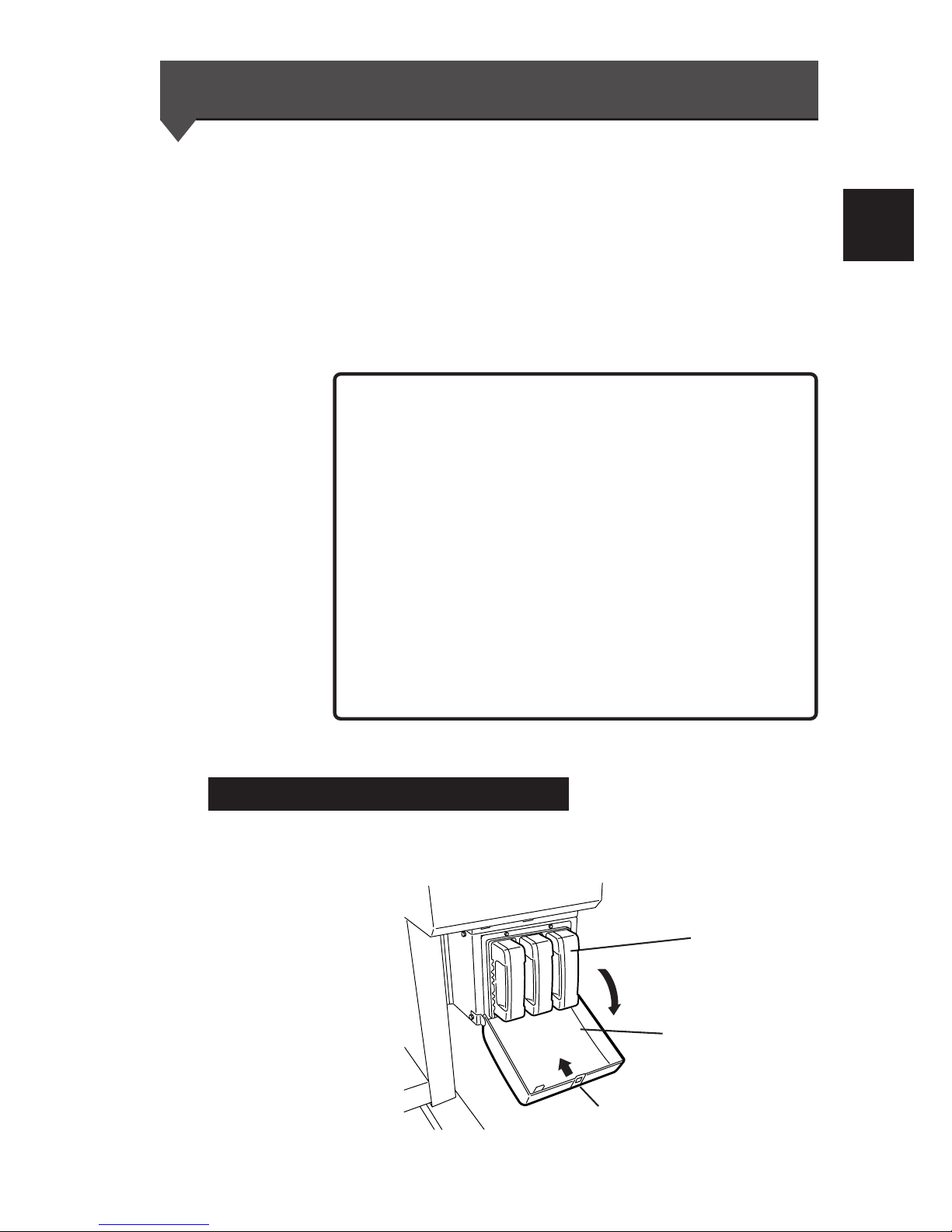
2-41
Section 2 Basic Operations
Replacing Ink Cartridges
This section describes how to replace an ink cartridge.
Ink cartridges should be installed in the following four cases:
- If ink has run out
- If an ink cartridge is not installed
- If a 4-color ink cartridge is to be replaced
- If a 6-color ink cartridge is to be replaced
The ink cartridge replacement procedure in each case is explained
below.
Ink Cartridge Replacement Procedure
1 Open the ink cover.
Ink cartridge
NOTES
Ink cover
Push here to open the ink cover.
- Do not remove the ink cartridge in the following cases:
• No power is supplied to the printer due to a power failure
or breaker action.
• An error other than ink end has occurred.
- Depending on the printer status, the ink in the ink box may
spill, causing malfunction.
- Select the offline state if the ink cartridge in which the ink
remains is replaced. (⇒ See Section 3, Ink Menu (5))
For ink replacement during printing, see "Replacing the
cartridge during printing".
- Make sure the ink cartridge is right side up before installing.
Page 86
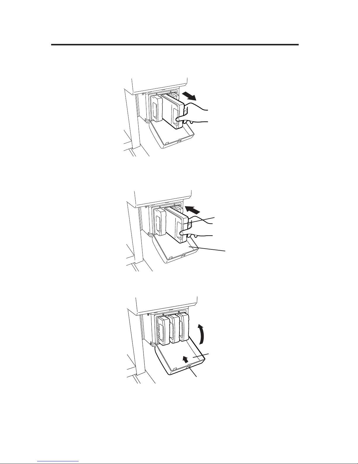
2-42
3 Insert a new ink cartridge into the printer.
4 Close the ink cover.
New ink cartridge
Ink cover
Ink cover
Push here to close the ink cover.
2 Remove the ink cartridge to be replaced from the printer.
Page 87

2-43
Section 2 Basic Operations
Replacing an Empty Ink Cartridge
1 The following guidance message appears:
2 Replace the ink cartridge according to the “Ink Cartridge
Replacement Procedure.”
OPEN R INKCOVER
CHANGE XX INK
XX: Ink name
C: CYAN
M: MAGENTA
Y: YELLOW
OPEN L INKCOVER
CHANGE XX INK
XX: Ink name
Bk: BLACK
Lm: LIGHT MAGENTA
Lc: LIGHT CYAN
5 End of ink cartridge replacement.
- If replacement ends normally, the printer returns to the offline or online
state.
- If replacement ends in an abnormal manner, an error message will be
displayed.
Go back to step 1 and repeat the procedure.
- The printer continues to print as long as ink remains in the sub-tank
during ink cartridge replacement.
Replacing Ink Cartridges
Page 88

2-44
If an Ink Cartridge is not Installed
1 The following guidance message appears:
2 Replace the ink cartridge according to the “Ink Cartridge
Replacement Procedure.”
OPEN R INKCOVER
SET XX INK
XX: Ink name
C: CYAN
M: MAGENTA
Y: YELLOW
OPEN L INKCOVER
SET XX INK
XX: Ink name
Bk: BLACK
Lm: LIGHT MAGENTA
Lc: LIGHT CYAN
Page 89
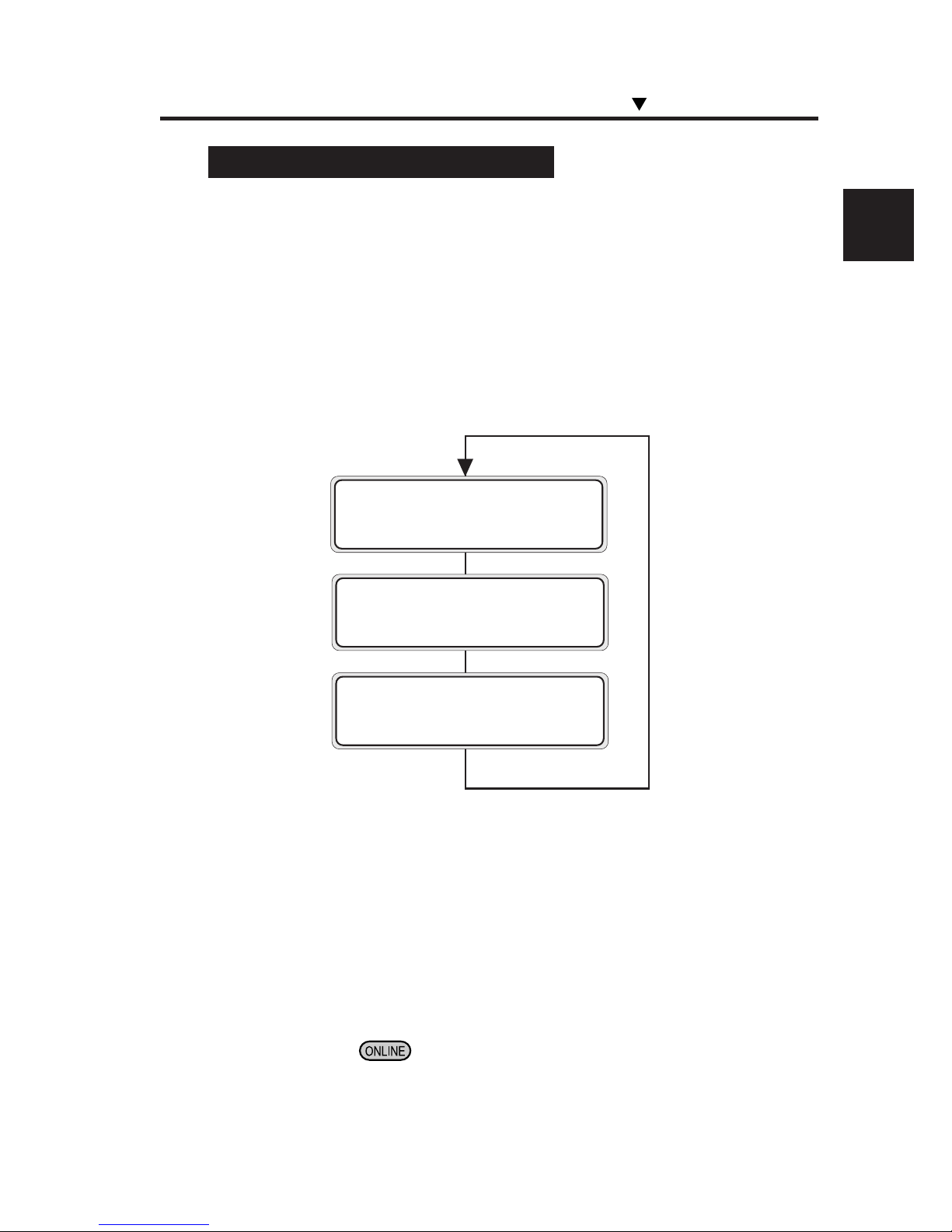
2-45
Section 2 Basic Operations
Replacing Cartridges during Printing
The ink cartridges can be replaced during online printing without
interrupting the printing operation. Accordingly, guidance for ink
replacement during the online printing is displayed on the second
line of the LCD. The following describes how the guidance is shown
if the ink cover is opened during online printing or if the ink in the
main cartridge is used up:
<If the Ink Cover is Opened>
The guidance that prompts you to close the ink cover is displayed
on the second line of the LCD. The printing operation continues if
ink is present in the sub tank even though the ink cover is open.
However, no ink is supplied to the sub tank because the ink cover is
open.
If the ink in the sub tank is used up, the print pause mode is activated
and the printing operation is interrupted until the ink cover is closed.
To recover from the interrupted state, close the ink cover and press
the
key. The pause mode is cancelled and printing will
restart.
PRINTING
ROLL: 104 / PAPER
PRINTING
INKCOVER IS OPEN
PRINTING
CLOSE X INKCOVER
XXXX:
L, R
Replacing Ink Cartridges
Page 90
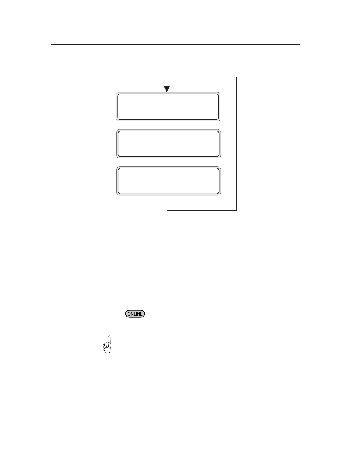
2-46
<If the Ink in Main Cartridge is Used Up>
The guidance that prompts you to replace the main cartridge is
displayed on the second line of the LCD. The printing operation
continues until the ink in the sub tank is used up. If replacement is
completed while ink remains in the sub tank, the printing operation
can continue without interruption.
If the main cartridge is not replaced even after the ink in the sub
tank is used up, the print pause mode is activated and the printing
operation is interrupted until the main cartridge is replaced.
To recover from the interrupted state, close the ink cover and press
the
key. The pause mode is then cancelled and printing will
restart.
PRINTING
ROLL: 104 / PAPER
PRINTING
OPEN X INKCOVER
PRINTING
CHANGE YY INK
XXXX: L, R
YY: Bk Lm Lc Y M
C
- The guidance concerning the ink replacement during the
online printing is displayed on the second line of the LCD
in turn, as the guidance mentioned above.
The printer can restart by operation performed to restart
after an error
.
HINT
Page 91
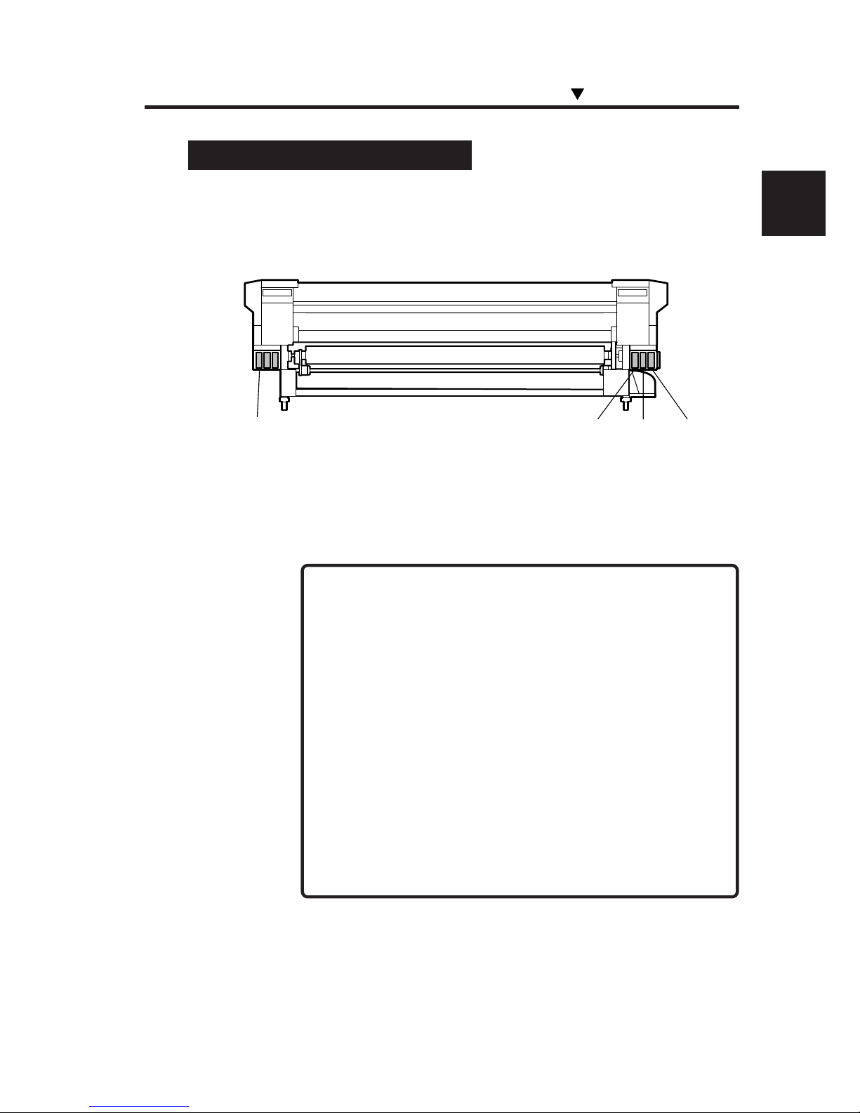
2-47
Section 2 Basic Operations
Replacing 4-Color Ink Cartridges
1 Prepare 4-color ink cartridge.
Set the cartridges in position to the target ink holder.
2 Then, replace the ink cartridges following "Ink Cartridge
Replacement Procedure."
Black
Yellow Magenta Cyan
NOTES
- Exchange between 6-color ink cartridges and 4-color ink
cartridges should not be carried out more than 5 times.
- When exchanging the cartridges between 4 colors and 6
colors, replace all cartridges. If even one color of a 4-color
ink cartridge has been set, the printer operates in the 4color mode.
- If 6-color data are received in the 4-color mode (4-color
ink cartridges are set), the host posts an error to the printer
and printing is disabled.
- Cleaning is executed for all 6 colors even in the 4-color
mode. Accordingly, Lc and Lm not used for printing are
also consumed. Adjustment patterns are printed in 6 colors.
Replacing Ink Cartridges
Page 92

2-48
OPEN R INKCOVER
CHECK XX INK
XX: Ink name
C: CYAN
M: MAGENTA
Y: YELLOW
OPEN L INK COVER
CHECK XX INK
XX: Ink name
Bk: BLACK
Lm: LIGHT MAGENTA
Lc: LIGHT CYAN
If an Ink Cartridge is not Detected
1 The following guidance message appears:
2 Replace the ink cartridge according to the “Ink Cartridge
Replacement Procedure.”
Page 93
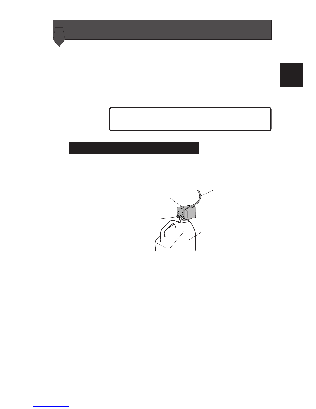
2-49
Section 2 Basic Operations
Waste ink bottle
Lever
Knob
Tube
NOTE
Replacing the Waste Ink Bottle
This section describes how to replace a waste ink bottle.
A waste ink bottle should be replaced in the following two cases:
- If the waste ink bottle is full
- If a waste ink bottle is not installed
The waste ink bottle replacement procedures for these cases are
explained below.
- Do not replace the waste ink bottle during printing.
Waste Ink Bottle Replacement Procedure
1 Loosen the knob and lift up the lever from the waste ink
bottle.
2
Wait for a while to drop the remaining ink into the ink tube.
3 Take out the filled waste ink bottle from the printer, and
securely cap the waste ink bottle.
Page 94
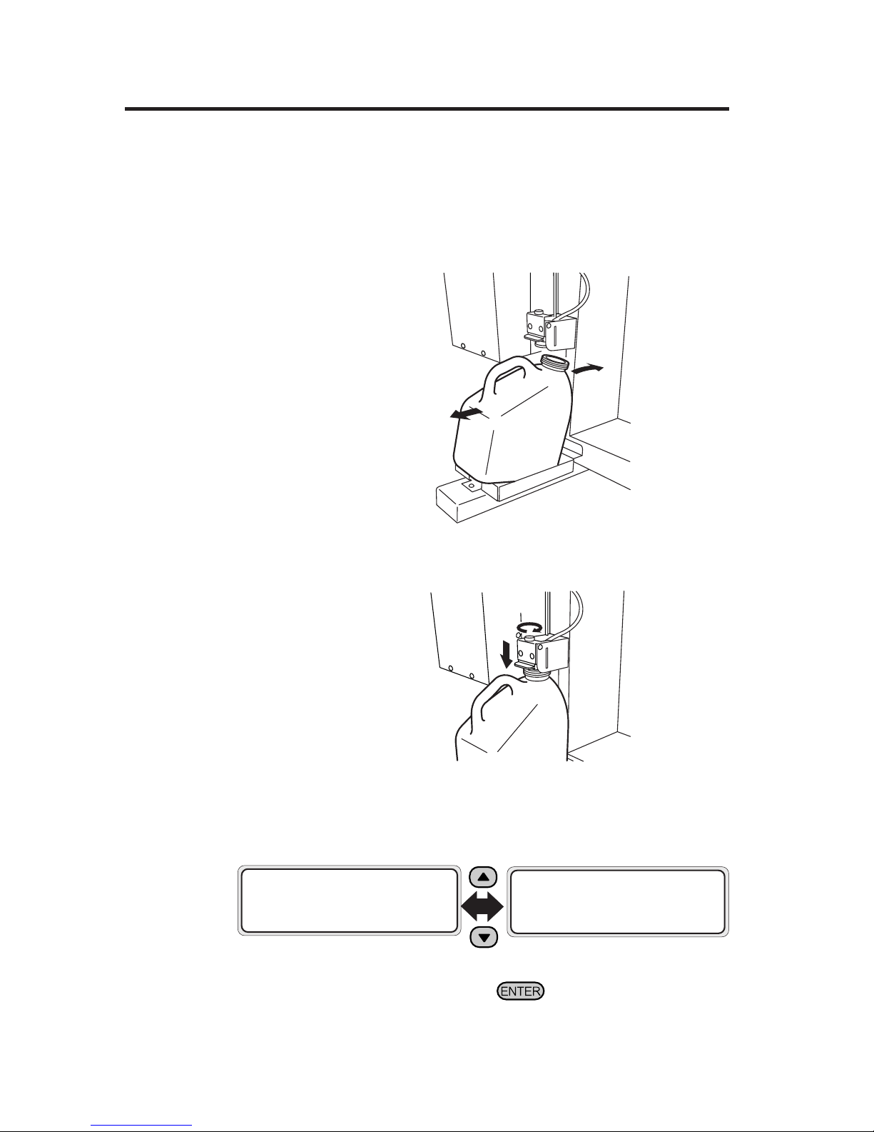
2-50
4 Wipe up any spilt ink in the waste ink bottle unit.
5 Lift the lever and mount a new waste ink bottle.
6 Drop the lever, insert the ink tube securely and tighten
the knob.
7 The waste ink counter setting selection message (reset
(clear)) will be displayed.
8 Select “YES” and press the key.
#INK COUNT RESET
✽NO
#INK COUNT RESET
✽YES
(1)
(2)
Page 95
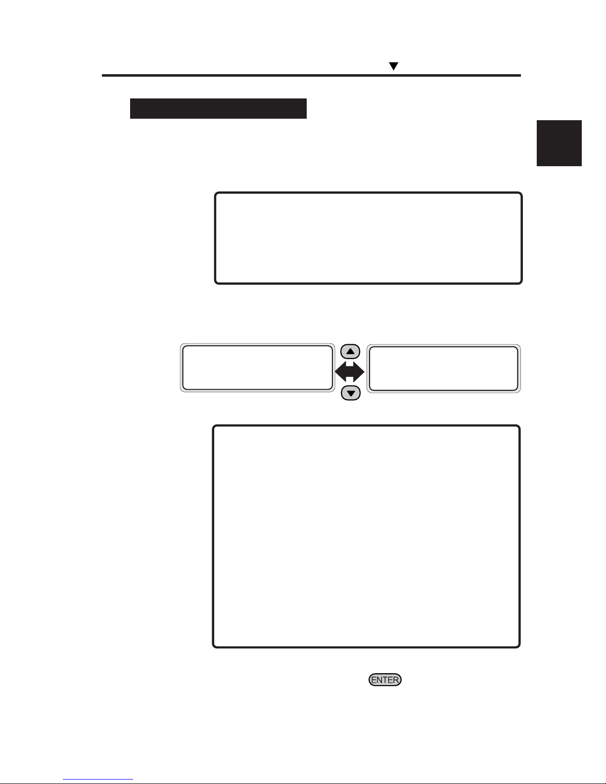
2-51
Section 2 Basic Operations
2 The waste ink counter setting selection message (reset
(clear)) will be displayed.
- The waste ink count is the amount of used ink (waste ink)
counted by the printer. When the count exceeds a certain
amount, an error is output prompting waste ink disposal.
It is a pseudo detection of waste ink full, not an actual
detection. Counting starts when the printer recognizes that
an empty waste ink bottle is set. Therefore, each time the
waste ink bottle is removed and mounted, *YES should be
selected to reset the waste ink counter. If this relationship
is not maintained, not only will the waste ink bottle full
detection counter malfunction, but also the waste ink bottle
could be full before a warning is output and the excessive
ink could spill out of the bottle.
3 Select “✽YES” and press the key.
#INK COUNT RESET
✽NO
#INK COUNT RESET
✽YES
NOTE
If the Waste Ink Bottle is Full
1 Replace the waste ink bottle according to the “Waste Ink
Bottle Replacement Procedure.”
- Check visually whether or not the waste ink bottle is full
before using the printer.
- If it is ful, replace it according to “Waste Ink Bottle
Replacement Procedure.”
NOTE
Replacing the Waste Ink Bottle
Page 96
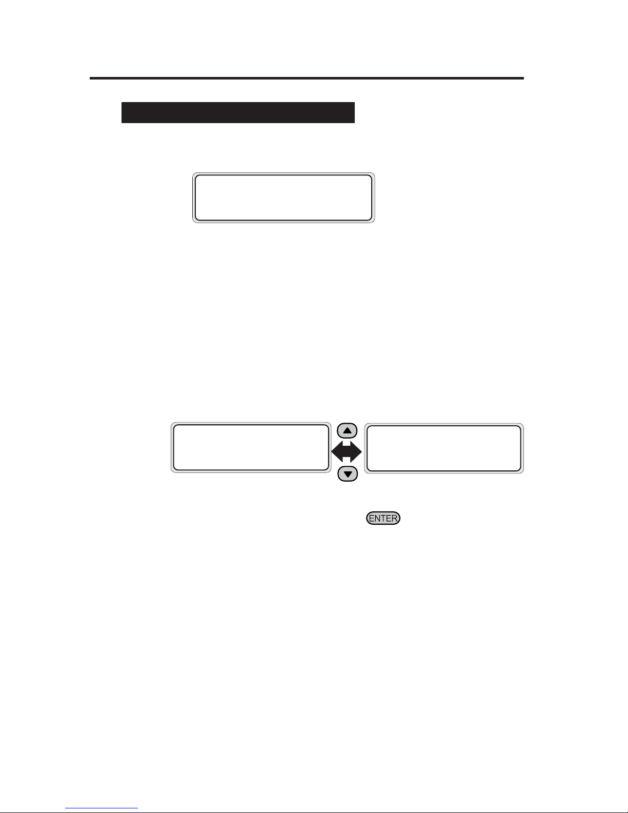
2-52
If the Waste Ink Bottle is not Installed
1 A guidance message appears on the LCD.
2 Insert a new waste ink bottle into the printer and install
the waste ink bottle cover.
⇒ See the Waste Ink Bottle Replacement
Procedure.
3 The selection message of the waste ink counter setting
(reset (clear)) will be displayed.
4 Select “✽YES” and press the key.
BOTTLE ISN’T SET
SET BOTTLE
#INK COUNT RESET
✽NO
#INK COUNT RESET
✽YES
Page 97
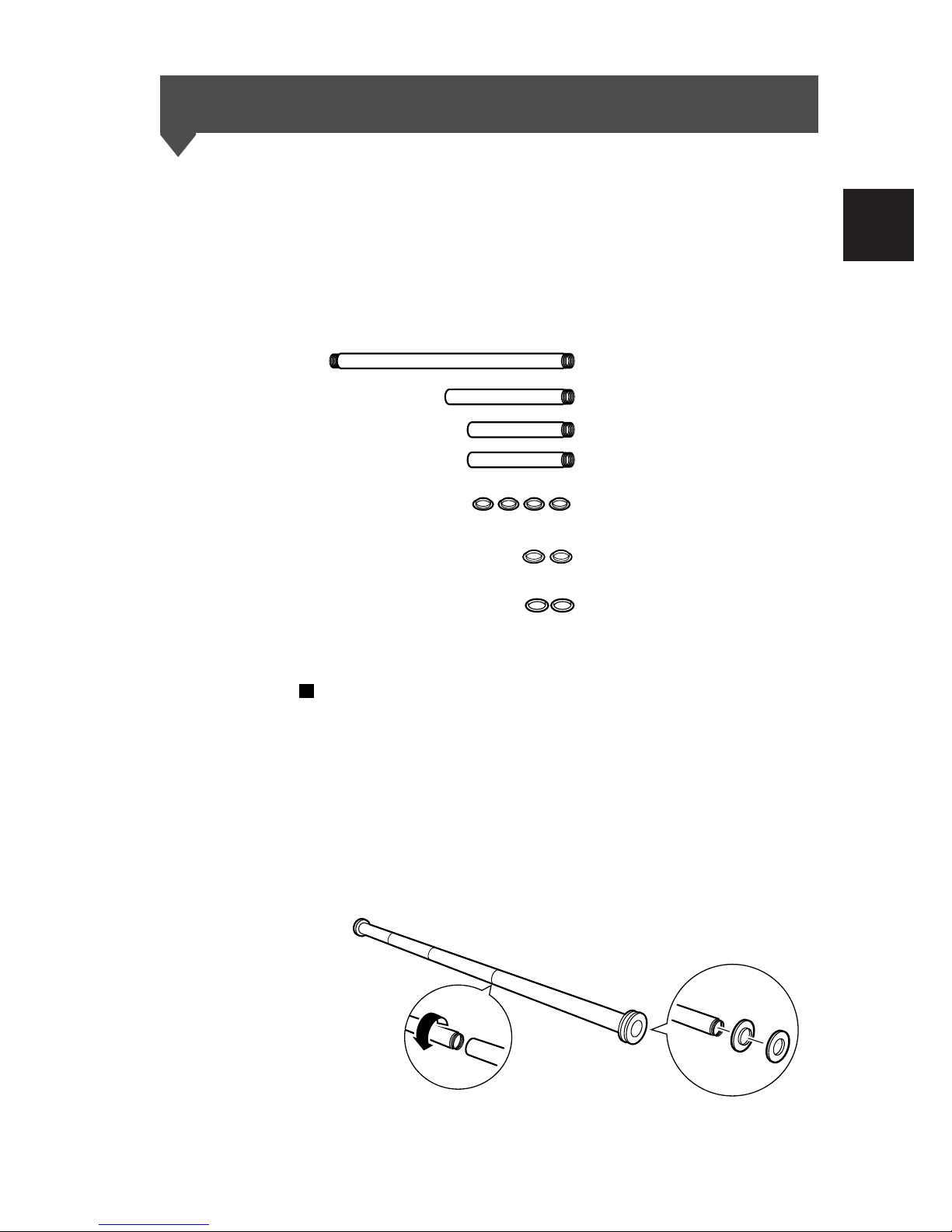
2-53
Section 2 Basic Operations
Tension Bar Length Adjustment
Use the same tension bars on the feed side and the take-up side.
Insert the exclusive flange and fixing ring before attaching the
tension bar on the take-up side.
One set of tension bars includes 2 S size (16 inch, about 40.6cm)
bars, 1 M size (24 inch, about 60.7cm) bar and 1 L size (48 inch,
about 123.3cm) bar; and 4 flanges.
Jointing method (feed side)
The bars connect by being screwed in to one another. If all 4 are
connected, the total length is 104 inches. The L size bar has male
joints on both ends, and must always be used. The M and S size
bars have female joints at one end for jointing to the L size bar.
Both ends of the jointed tension bar should be male to attach the
flanges.
L size (48 inch): 1 bar
M size (24 inch): 1 bar
S size (16 inch): 2 bars
Flanges: 4
Flanges for use with tension bar guide: 2
Fixing rings: 2
Page 98
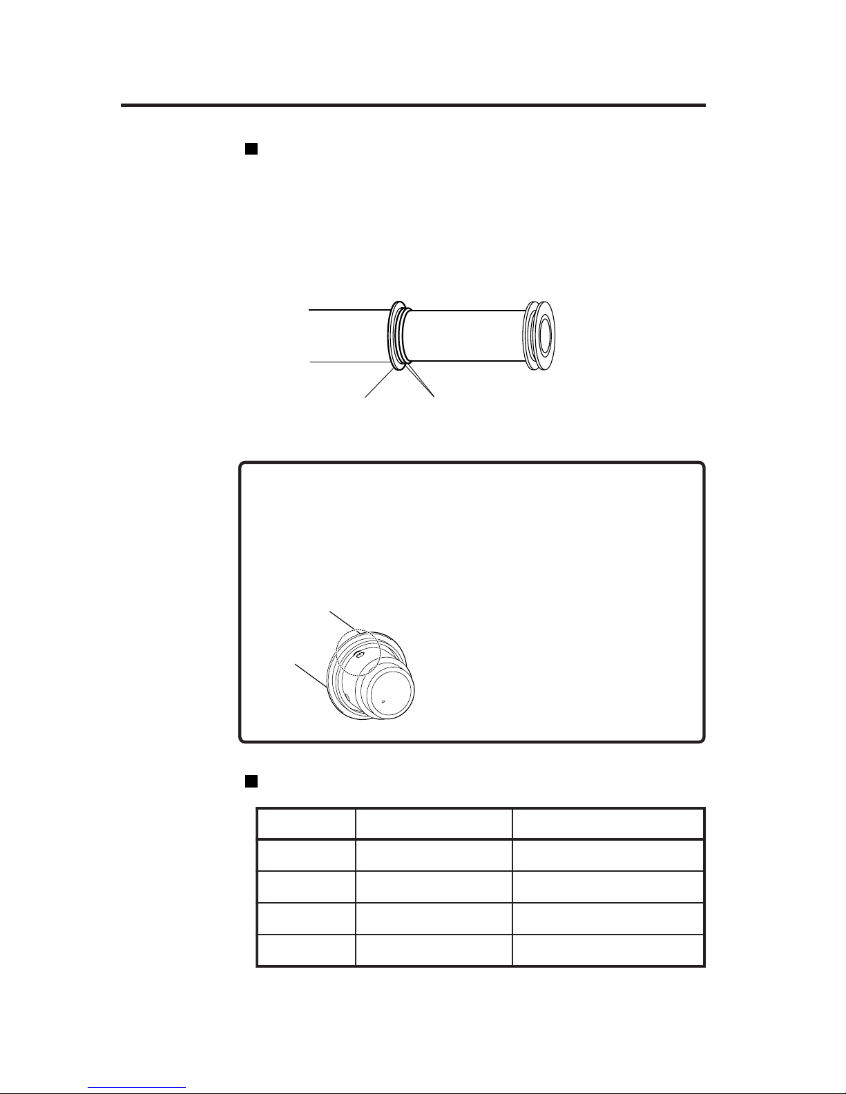
2-54
Jointing method (take-up side)
Set the flanges and fixing rings for exclusive use on the take-up
side as shown in the figure. After setting them, joint the bars as on
the supply side.
Both ends of the jointed tension bar should be male to attach the
flanges.
-When inserting the tension bar into the
flange, match the positions of the
depression in the inner circumference
in the flange and the tension bar thread.
-When setting the fixing ring, clean the fixing ring and the
tension bar (for example by wiping with alcohol). If dirt
remains, the flange can become displaced during wind-up,
causing the wound-up media to be displaced.
CAUTION
desuseziShtgnelrabnoisneThtdiwaidemgnihctaM
Lhcni84hcni84othcni63
S,Lhcni46hcni46othcni94
S,S,Lhcni08hcni08othcni37
S,S,M,Lhcni401hcni401othcni98
Examples of tension bar combination
Fixing rings
Flange for take-up
Page 99
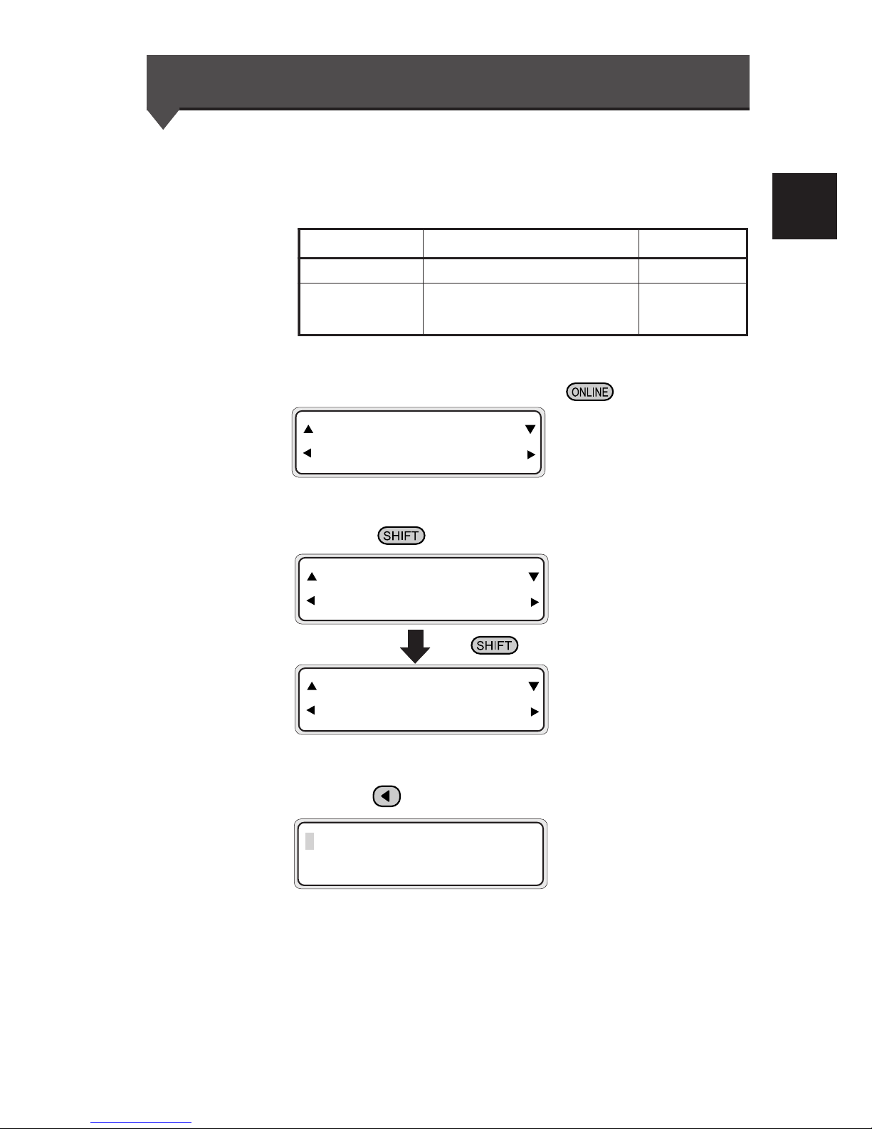
2-55
Section 2 Basic Operations
Head Cleaning "CLEANING"
This section explains how to clean the head.
Three types of cleaning are available. Use either one according to
the application.
1 Put the printer offline. (Press the key.)
2 Press the key to display the CLEANING menu.
3 Press the key to enter the head cleaning menu.
INK ENTRY
PAPER F. ADJ
SERVICE FEED
CLEANING
INK ENTRY
PAPER F. ADJ
# CLEANING
>NORMAL
Cleaning type Application Ink consumption
NORMAL
Recovery from dot-off in printing 2.45 cc
STRONG
Recovery from jam
Recovery from dot-off in printing
if NORMAL fails to recover
10.82 cc
Page 100
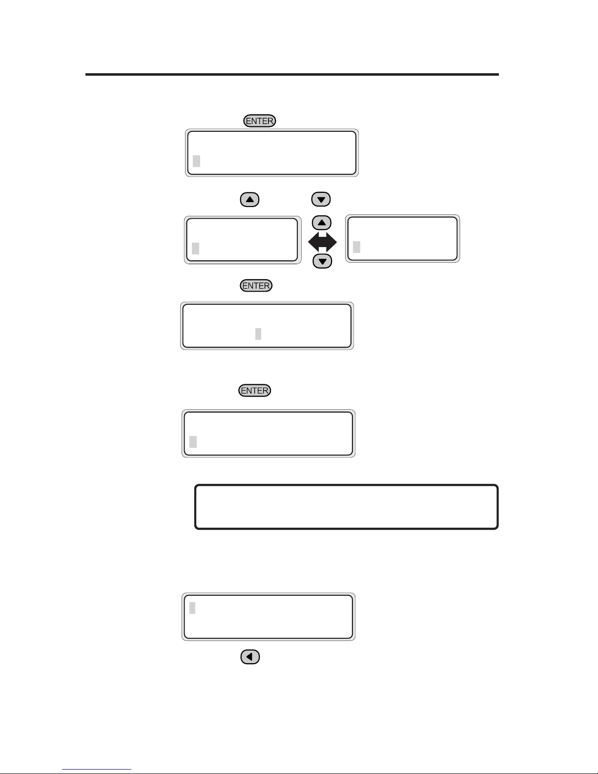
2-56
4 Press the key.
5 Press the key and key to select a cleaning option.
6 Press the key.
7 Make sure that the waste ink bottle is not full, and then
press the key again.
NOTE
- The cleaning takes several minutes.
8 When the cleaning is completed, the screen is returned
to step 3 automatically.
9 Press the key to return to the original offline mode.
#CLEANING
✽WAIT A MOMENT XXX
XXX : Figure will be incremented
in about 10 seconds.
# CLEANING
✽ NORMAL
#CLEANING
✽BOTTLE OK?
#CLEANING
>NORMAL
#CLEANING
✽STRONG
#CLEANING
✽NORMAL
 Loading...