

Page 1
Read this User’s Guide before operating the printer.
Keep this manual for future reference.
User's Guide
U00130312100
Solvent Ink Color Inkjet Printer
IP-6620
Seiko I Infotech Inc.
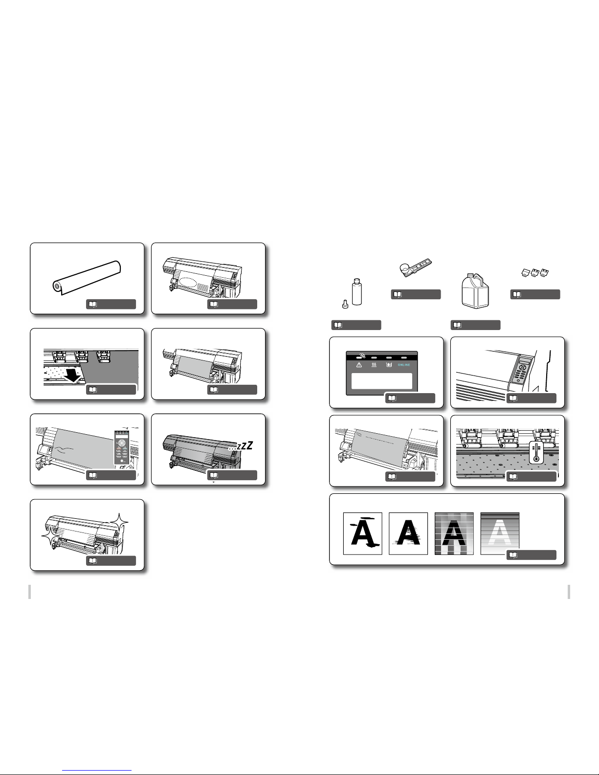
Before printing Loading the media Adjustment Maintenance
Advanced
operations
Troubleshooting Menu tree Appendix
Page 2

2 3
IP-6620 Solvent Ink Color Inkjet Printer User's Guide
Document Number U00130312100, First edition, July 2013
Copyright © 2013 by Seiko I Infotech Inc.
All rights reserved
The contents of this manual may be changed without prior notice.
Seiko I Infotech Inc. reserves the right to make changes without notice to the specications and materials contained
herein and shall not be responsible for any damage (including consequential) caused by reliance on the materials
presented, including but not limited to typographical, arithmetic, or listing errors.
Please address any questions, comments, and suggestions to the regional oce on:
http://www.s eiko-i.com/corp/oces.htm l
This guide acknowledges the following trademarks:
is a trademark of Seiko Instruments Inc.
All other trademarks are the properties of their respective companies.
This equipment has been tested and found to comply with the limits for a Class A digital device, pursuant to Part 15
of the FCC Rules. These limits are designed to provide reasonable protection against harmful interference when the
equipment is operated in a commercial environment.
This equipment generates, uses, and can radiate radio frequency energy and, if not installed and used in accordance
with the instruction manual, may cause harmful interference to radio communications. Operation of this equipment
in a residential area is likely to cause harmful interference in which case the user will be required to correct the
interference at his own expense.
The CE mark, that shows that the products sold in the EU are conformed to the requirements of EC directive, is
statutorily required to be axed to the products.
In each directive, the scope of directive to be applied to equipment is explicitly dened. Our company’s product IP6620 conforms the EMC directive (2004/108/EC), low voltage directive (2006/95/EC) and RoHS Directive 2011/65/EU.
Inquiry of CE mark:
Seiko Instruments GmbH
Siemensstraße 9, D-63263 Neu-Isenburg
Germany
Tel: +49- 6102-297-0
Fax: +49 -6102-297-320
Seiko I Infotech Inc.
8 Nakase 1-chome, Mihama-ku, Chiba-shi, Chiba 261-8507, Japan
Phone : +81 43 211 1363
Fax : +81 43 211 8709
Thank you very much for purchasing the IP-6620 Color Inkjet Printer (hereafter simply called the printer.)
IP-6620 supports media up to 64 inch width. The printer is a color inkjet printer using solvent ink and equiped
with USB 2.0 interface.
The printer has two types of specications, 7 color specications and 6 color specications, depending on the
number of print heads.
Thi s gui de pr ov ide s exp la nat ion s for t he I P- 662 0 7 col or sp ec ifi ca tio ns mo de l. Ho wev er, in di vid ual
information is given when necessary.
This guide, the IP-6620 Solvent Ink Color Inkjet Printer User ’s Guide, describes the features and functions
of the printer and the printing procedure. In addition, troubl eshooting is also included. Read the sec tions
suitable for your purpose.
The following items should be read before using the printer to ensure correct and safe operations.
- Safety precautions
- Components delivered with this produc t
- Manual legend (Notational rules)
Keep this guide in a place where you can quickly access it at any time.
Introduction
Page 3
4 5
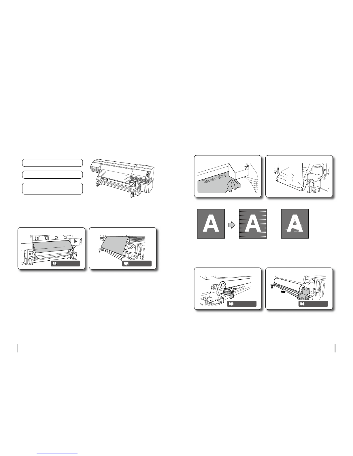
To maintain an excellent print quality
Load the media on the feed unit.
1. Load the media correctly
Set the media on the take-up reel (TUR) unit.
The printer has been designed to facilitate media installation.
If the media is not set correctly…
The media may skew or contact the print heads, greatly decreasing the print quality.
Media jam caused by skewed media
Raise the media with the media lifter.
Incorrect winding
Move the take-up reel unit toward you.
Colors on the right and left
dier due to skewed media.
The printout is not clean due to
media contacting the print heads.
<Examples>
Be sure to pay attention to the following three points to maintain an excellent print quality and use the printer over
a long time.
(1) Load the media correctly
(2) Make proper adjustment
(3) Perform the necessary
maintenance operations
page 37 page 47
page 36 page 44
Page 4
6 7
Media advance
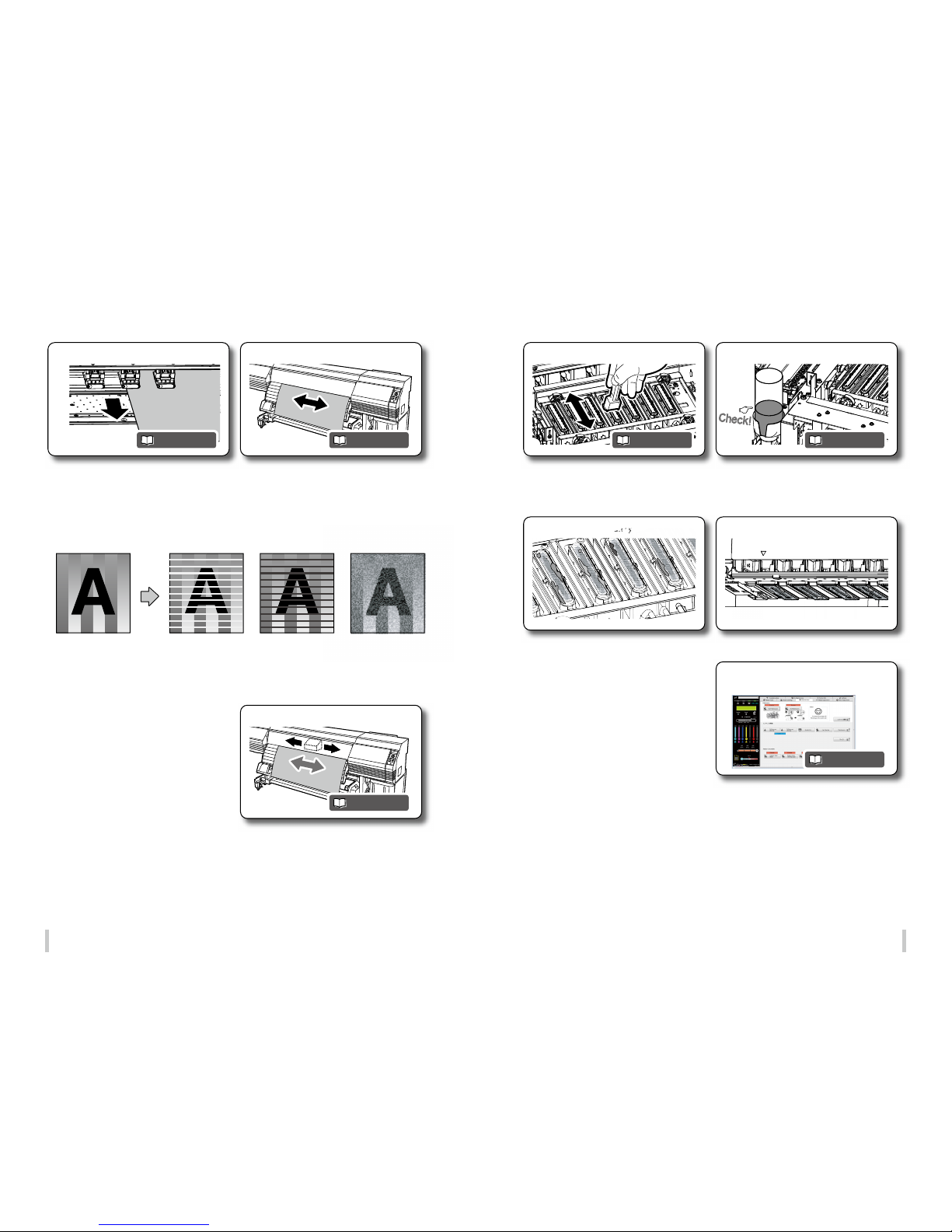
2. Make proper adjustment
Bidirectional print position
Adjustment can be performed automatically.
If these adjustment operations are not performed when
using a new media…
The ink may not be output to the right position and the print quality may decrease.
<Examples>
Banding (white or black bands) may appear if
media advance adjustment is not performed
correctly.
Grains may become
visible and the image
may appear blurred if
the bidirectional print
position is not adjusted.
The printer has been
designed to facilitate
adjustment.
The capping unit is dirty. The print heads are dirty.
Maintenance status and periods can be
grasped at a glance.
Use CP_Manager…
to make maintenance operations easier.
Clean the capping unit.
3. Perform the necessary maintenance operations
Check the wiper cleaning liquid.
If the printer is used when not clean…
The print quality may not only decrease but the printer may also malfunction.
page 59 pag e 76page 66
page 59
page 84
page 33
Page 5
8 9
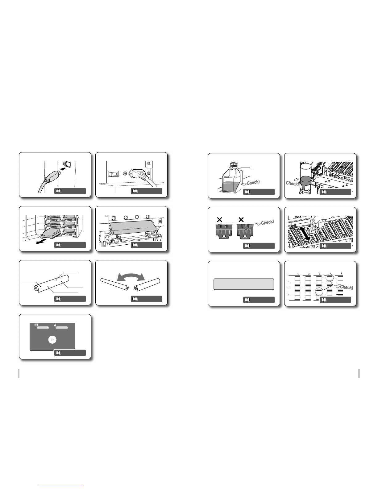
POWER
NOZZLE PRINT PH.RECOVERY
Media advance value
Media name
Head height
Color stripe
Connect to a computer.
Replace the ink cartridge.
Register the media.
Turn o the power.
Turn on the power.
Load the roll media.
Replace the media.
Starting out...
#PH RECOVERY
>NORMAL
Check the Waste ink bottle.
Check stains on the wiper blade.
Perform a print head cleaning
[NORMAL].
Check the wiper cleaning liquid.
Clean the capping unit.
Perform a nozzle print.
Regular Inspection (Maintenance)
pa ge 31
page 163
page 42
page 30
page 29
page 36
page 43
page 82
page 86
page 79
page 84
pag e 76
page 80
Page 6
10 11
Print on a thick media.
Change the media advance adjustment
value during printing.
Adjust the media during printing.
Clean the printer.
Print on the margin of the media.
Change the heater temperature
during printing.
Switch o the printer for a long
period of time.
When you want to...
PERFORM DAILY
MAINTENANCE NOW
Wiper cleaning liquid
Wiper sponge Wiper blade
Waste ink bottle
Replace consumables.
A warning message is displayed.
The media is not straight.
The panel operation is not possible.
The heater does not warm up.
Smears or stripes appear on the print.
pa ge 132
pa ge 15 3
pa ge 148
page 92
pa ge 143
pa ge 15 7
pag e 104
Replacement and trouble
page 84
page 178 pa ge 17 3
page 36 pag e 168
page 182
page 82
page 86page 89
Page 7

12 13
Table of Contents
Introduction .....................................................
3
Table of Contents ...........................................
12
Safety precautions .........................................
14
Manual legend (Notational rules) ...............
19
Components delivered with this product .
20
Operating conditions ....................................
21
Installation and maintenance space ..............................................
21
Environmental conditions ....................................................................
22
Before printing
Printer front (take-up side) ....................................................................
24
Appearance / Main components
and their functions ........................................
25
Printer rear (supply side) ........................................................................
25
Printer interior ...............................................................................................
26
Operation panel ..........................................................................................
27
Printer heater unit ......................................................................................
28
To turn the printer on and o ......................
29
Power-on procedure ................................................................................
29
Power-off procedure ................................................................................
30
To connect the USB cable .............................
31
Online and oine ..........................................
32
Online ................................................................................................................
32
Offline ................................................................................................................
32
CP_ Ma na ge r ....................................................
33
Supported media ...........................................
34
Vinyl ....................................................................................................................
34
Banner ...............................................................................................................
34
Mesh banner (with liner) .......................................................................
34
Backlit banner (FF) .....................................................................................
34
Solvent printing coated paper ...........................................................
34
Loading the media
Loading the media on the printer ..............
36
Procedure to load roll media ..............................................................
36
Replacing the media when the end of the roll is reached
.....
43
Replacing the media after a media jam .......................................
43
Setting the media remaining length .............................................
43
Setting the media on the take-up reel unit
.....
44
Tension and loose mode setting procedure ............................
44
Procedure to set the media on the TUR unit ............................
47
Removing the media .....................................
51
Procedure to remove the roll media (output side) ...............
51
Procedure to remove the roll media (feed side) .....................
53
When using 2-inch tubes ......................................................................
54
Cutting the media ..........................................
55
Adjustment
Before making adjustment ..........................
58
Adjustment methods ....................................
59
Adjusting media feeding: Media advance adjustment ......
59
Correcting ink output position: Bidirectional adjustment
66
Maintenance
Daily maintenance .........................................
74
Routine maintenance ....................................
76
Performing capping unit cleaning and normal
cleaning at the same time ....................................................................
76
Performing normal cleaning independently ..........................
79
Print the nozzle print pattern .............................................................
80
Nozzle map setting ....................................................................................
81
Maintenance when a message is displayed ...
89
Head guard cleaning ...............................................................................
92
Maintenance when the printer is dirty ......
92
Edge guard cleaning ................................................................................
94
Front cover cleaning .................................................................................
95
Paper guide cleaning ...............................................................................
95
Pressure roller cleaning ...........................................................................
95
Platen cleaning ............................................................................................
96
Preparing the sheet mount cleaning ............................................
97
Performing sheet mount cleaning ..................................................
97
After the operation of the day ..................
102
Advanced operations
When not using the printer for more
than 2 weeks ................................................
104
Service cleaning ......................................................................................
105
Head wash ...................................................................................................
107
Priming the ink system after head wash ...................................
112
Check the printer information ...................
114
Check the remaining ink level ..........................................................
114
Export printer information .................................................................
115
Check remaining media length ......................................................
116
Check the USB connection status .................................................
118
Check the firmware version on the printer ..............................
119
Check the total print length .............................................................
120
Handle the media .......................................
122
Create a new media preset ...............................................................
122
Minimize the right and left margins ............................................
125
Prevent the media from sticking and wrinkling ..................
128
Prevent the media from lifting up .................................................
131
Print on a thick media ...........................................................................
132
Prevent the ink from spreading over the printout ..............
135
Change the automatic cleaning timing .....................................
137
Copy a media preset ..............................................................................
139
Change the type of the preset media without
reloading the media ...............................................................................
141
Feed or rewind media ..........................................................................
142
Move the print start position ...........................................................
143
Exit origin setting mode .....................................................................
144
Adjust the head margin before printing ..................................
145
Reinstall the edge guards during printing ..............................
146
Remove some media wrinkles during printing ...................
148
To change the printer’s basic settings ....
149
Turn the warning beep off ................................................................
149
Cleaning options ..........................................
151
Perform cleaning only for the specified print head ...........
151
Controlling the media advance
adjustment value ........................................
153
Change the media advance adjustment value
during printing ..........................................................................................
153
Print conditions ...........................................
154
Print modes ................................................................................................
154
Set the carriage speed ..........................................................................
155
Print speed ..................................................................................................
156
Adjust the heaters temperatures ............
157
Procedure to set the heaters temperatures .............................
157
Display the heater control menu ..................................................
158
Key operations in the heater control menu ...........................
158
Exit the heater control menu display ...........................................
159
Set the heater preset temperature ...............................................
159
Select the standby time ......................................................................
160
Out of ink while printing ...........................
162
Install and replace an ink cartridge ..............................................
163
Move the printer .........................................
166
Troubleshooting
Check the problem .....................................
168
How to clear media jams ............................
171
When an error message is displayed .......
173
The media has skewed. ..............................
177
Warning messages ......................................
178
Clear missing dots (nozzle clogging) ......
179
Strong cleaning .........................................................................................
179
Fill the cap with ink .................................................................................
181
Solve print quality issues ...........................
182
The print is pale. .......................................................................................
182
The printout is blurred or grains appear. ..................................
182
Missing dots are found at the beginning of printing. ......
182
The media is curled or wrinkled. ...................................................
183
White stripes appear on the print. ...............................................
184
Black stripes appear on the print. .................................................
186
The printout is not clean. ...................................................................
188
Contours of objects are blurred. ....................................................
190
Vertical banding appears at the printout edges. .................
192
Different bands appear on the printout right
and left sides. ..............................................................................................
193
Menu tree
Appendix
Basic specications ......................................
216
Consumables ................................................
217
Options .........................................................
220
Distributors .................................................
221
For inquiries about the printer ........................................................
221
Page 8
14 15
Safety precautions
The following symb ols are used in the guide to ensure th e printer’s proper oper ation and to prevent the
printer from being damaged. Follow the instructions marked with these symbols:
WARNING
Failure to follow the guidelines marked with this
sym bo l co uld r es ult i n serio us p ers onal inj ury or
death.
CAUTION
Failure to follow the guidelines marked with this
sym bo l co uld r es ul t in mi no r per so na l inj ur y or
damage to the product.
Example of symbols:
This symbol ( Triangle ) denotes items that require special care while
executing a certain procedure or operation.
This symbol ( Crossed circle ) denotes items that are forbidden.
This s ym bol ( P lain c irc le ) de note s ite ms you s hou ld fo llo w to
prevent accidents or injury.
WARNING
Be sure to read warnings below before use.
Use the power supply voltage sp ecied on the nameplate.
Avoid overloading the elect rical outlet used for the printer
with multiple devices.
Make sure that the printer is well ground ed. Failure to
ground the printer may result in ele ctrical shock, re, and
increased susceptibility to electromagnetic interference.
Always hold the power cord by the plu g when connecting
to and disconnecting from t he power outlet.
Never pull on the cord directl y. Doing so may damage the
cord and create a risk of re and elec tric shock.
Do not use a conversion plug.
Do not disassemble or repai r the printer yourself. Do not
reinstall the printer in a new lo cation. In such cases, call
your service representative.
Do not damage, break, pro cess, or heat the power
cable. If it is damaged, repl ace it with a new one. Using a
damaged power cable may caus e re or electric shock.
Never use the printer in a place of ex treme humidity or
any place where it can possibly b e splashed by any liquid.
If any liquid enters inside the printe r, it could lead to re,
electric shock, o r a breakdown.
Do not allow metal or liquids to tou ch the internal parts
of the printer. This may cause re, elec tric shock, or other
serious hazards.
Do not disconnect or conne ct the power cord with wet
hands. Doing so may lead to ele ctric shock.
Ink used in the ink cartri dges is combustible. Do not use
or store ink cartridge s near open ames, sparks, or o ther
sources of ignition.
Operate the printer caref ully near the printer's movable
parts, so that your hands o r your clothes are not caught
in the printer.
Install and operate the pri nter in a well-ventilated area.
Otherwise the ope rator may feel sickish. In such a case,
take a rest in a well-ventilated pl ace.
Media rolls are heavy. Handle the m with care using
a dolly or other tools to prevent the m from falling.
Dropping a media roll could c ause personal injury or
damage to the printer.
It is recommended to carr y media rolls with a dolly.
Be careful not to let ink come into cont act with your skin
or clothes. If ink touches your s kin, immediately wash it
o with soap and water.
Turn o the printer, unplug the power cord from the
power outlet, and contac t your service representative in
any of the following cases. Using t he printer continuously
in an abnormal state may result in an a ccident or re.
- Smoke, st range noise or smell is generated fr om the
printer or the printer is overheated .
- Ther e is smoke or an unusual smell coming from the
printer.
- The pr inter is making an unusual noise during
normal operation.
- A piece of m etal or a liquid (not part of cleaning an d
maintenance routines) has touched inter nal parts of
the printer.
- An erro r requiring service by a serv ice representative
occurs.
Avoid contact between sk in, eyes, and clothing and the
printer’s following consumable s: ink, storage liquid,
cleaning liquid, cap cleaning liquid, wiper cleaning liquid,
and waste ink.
- In case of co ntact, immediately wash your sk in with
soap and water.
- Use an appr oved eye wash station if ink splashed
into your eyes and consult a doctor if n ecessary. If an
approved eye wash station is unavail able, rinse your
eyes with cold water and consult a doc tor. Remove
clothing soaked with ink to avoid conta ct with your
skin.
Do not swallow ink. If swa llowed, do not induce vomiting
but seek immediate medic al attention.
Do not place the printer on an unst able table or at a slant
place. If it falls, it may lead to injur y.
Do not touch heater surface s in the media path. This may
cause burns.
Keep ink cartridges an d waste ink bottles out of the reach
of children.
CAUTION
Be sure to read warnings below before use.
CAUTI ON
Make sure the media rolls ar e secured when stored. Th ey are heavy and may cause injury i f they roll or fall.
To ensure safe operation of the Printer, pay attention to all the warnings and cautions contained throughout
this manual.
Page 9

16 17
Power supply
1. Install the printer near the socket. To be able to pull out the power plug in an emergency, the power
socket must be reached easily.
2. Do not share the power supply with noise generating devices such as a motor.
3. Use the power supply voltage specied on the nameplate.
4. Monthly turn o the printer and check the following:
- T he power plug is securely inserted into the socket.
- No dust is accumulated between the p lug terminals and the socket. When dust is found, clean the area
with a dry cloth.
Printer
1. Do not place anything on the top of the printer. Do not rest your elbows on the printer.
2. Do not apply shock or stress to the printer.
3. During the print operation, do not open the front cover, nor set the pressure roller lever to the open (top)
position. Otherwise the printer operation will end.
4. Do not clean the cover’s surface with benzene or paint thinner. This may damage the printer’s paint. Clean
the cover’s smear with a soft cloth. If the cover is considerably smeared, wipe it o with a cloth moistened
with water-diluted neutral detergent. If it is not cleaned, the printer’s surface paint may be damaged.
5. Always use the SIIT-specified attachments and options. The other products may degrade the image
quality, damage the printer, and make maintenance impossible.
Regular inspection and maintenance
Due to solv ent ink char acteri stics, in spect ion and mai ntenance n eed to be pe rfor med peri odical ly. (For
details on maintenance, see the Maintenance section star ting on
page 73
.)
1. Perform the start maintenance every day before star ting using the printer.
2. Pay particularly attention to the items below.
- Supply wiper cleaning liquid when the bottle is empty.
- Print heads are highly-precise parts. Do not wipe the nozzle surface directly.
3. If you stop using the printer for more than 2 weeks, perform the ser vice cleaning.
4. If, after the service cleaning, you have left the printer for a long time and you start printing with the
printer again, be sure to perform the head cleaning operation and to prime the ink system.
Consumables
1. SIIT ink cartridges should be installed before the Install By date printed on the pack. Other non-genuine
ink cartridges may damage the printer. In this case, printer repair fees will borne by you.
2. To guarantee print quality, expiration dates are indicated for ink cartridges, cleaning liquid cartridge sets,
and storage liquid cartridge sets. Use these consumables before their expiration date.
3. Put used ink cartridges into a plastic bag and dispose of them as industrial waste. Observe local
regulations for disposal of consumables.
4. Unpack the SIIT ink cartridges only to install them. Do not store SIIT ink cartridges in direct sunlight. Store
the SIIT ink cartridges in a cool, dry place. This prevents deterioration of the ink during storage.
5. Do not disassemble the ink cartridges. They are intended for single use only.
6. Do not drop the ink cartridges. Avoid shock to them. The drop or shock may cause an ink leakage.
Media
Supported media
The Printer supports solvent inkjet media of the types below. Note that print conditions may change depending
on environmental conditions and the media production batch. So you are recommended to test the print with the
media beforehand.
For details, contact your service representative.
z
Vinyl
z
Banner
z
Mesh banner (with liner)
z
Backlit banner (FF)
z
Solvent printing coated paper
Precautions when storing media
z
When storing media, packed or unpacked, avoid direct sunlight and humidity. To avoid dust put the
media into a box or a bag, and keep it in a cool and dark place.
z
Avoid rapid temperature change to prevent condensation.
z
Do not store media upright. A media stored upright may be deformed, move on the roll due to its weight,
or may its edges may be damaged.
z
Do not pile up roll media.
z
Make sure the media rolls are secured when stored. They are heavy and may cause injury if they roll or fall.
Precautions when disposing of media
z
Dispose of media or printout in compliance with all local, state, and federal regulations.
Precautions when using media
z
Do not subject unpacked media to temperature and humidit y variations. Before loading the media on
the printer, leave the media in the operating environment for three hours or more. Note that ambient
humidity variations caused by turning on or o the air conditioner may aect the media.
z
The media may curl at low temperature, and wrinkle at high temperature. Keep the temperature around
23°C and the humidity around 50% when you use the media.
z
Do not use a media when a part of it is scratched, wrinkled, curled, or that is covered with foreign matters.
Never use a damaged media, as the right and left edges of the media are especially critical to feed media
on the printer. Also, do not drop the media and avoid water stains, which may degrade the image quality
and cause the printer to malfunction.
z
Do not touch the printed part of the media. Always hold the media by the margin. The image quality may
be degraded by human sebum and sweat.
z
If the media is wound in the shape of a cone, correct the winding before loading and using the media.
Precautions when handling printouts
z
Do not touch the printed surface of the media before the ink dries, or especially 24 hours after printing.
Handle the printout by the margins.
z
Do not scratch the printout to avoid lost or transfer of colors. To avoid color transfer, do not stack printed
media on one another with their printed surface facing in contact.
z
Do not put printed media on a printout from a copier or laser printer. The printouts’ ink or toner may make
the two printouts to stick together.
z
Note that ink on a printed surface may come o if the surface is rubbed hard or scratched.
z
The printed image may bleed or disappear if scratched or left while being wet.
Page 10
18 19
Other precautions
z
Media loses its color and quality with age. Check the media condition and select the media in the best
condition.
z
Cut the media carefully, as paper dust may make irregular surfaces.
z
When adhesive-backed media is applied, some adhesive agent may be left on the platen, which may
cause a media jam. So clean the agent completely with a soft cloth moistened with the neutral detergent.
Available area on media
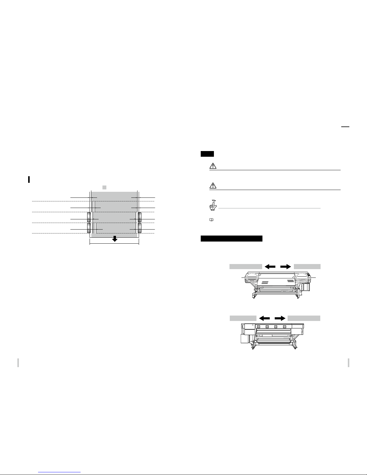
The available area on media in the scanning direction depends on the media width, the media edge guards
application, and the presence pf the color stripe. With the media edge guards and color stripe applied, the available
area decreases by 34.9 mm on the right and 10.0 mm on the left.
Color stripe :NO
Media edge guards :NO
Color stripe :YES
Media edge guards :NO
Color stripe :NO
Media edge guards :YES
Media width
Color stripe :YES
Color stripe :YES
32.6 mm
27.6 mm
10.0 mm 10.0 mm
10.0 mm
5.0 mm 5.0 mm
5.0 mm
Without mesh printing kit nor wide type media
edge guards for platen sheet
Printable area
Manual legend (Notational rules)
The notational rules used for explanation in this guide are as follows:
Marks
WARNING
Boxes marked with a WARN ING describe points of caution to avoid serious personal injury.
CAUTI ON
Boxes marked with a CAUT ION describe point s of caution to avoid injury to yourse lf or damage to the printer.
TIP:
This mark indicates useful inf ormation, additional items and imp ortant operations.
Reference mark
This mark is followed by a reference section or page number.
Capping unit side and wiping unit side
To identify the printer’s right and left, this guide mentions the capping unit side and wiping unit side as follows.
Viewed from the printer’s front (media take-up side)
Maintenance area side Capping unit side
Viewed from the printer’s rear (media supply side)
Maintenance area sideCapping unit side
A maintenance area is arranged. Capping unit is equipped.
Page 11
20 21
Operating conditions
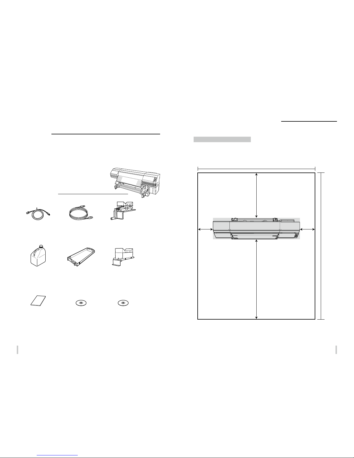
Installation and maintenance space
Adequate space is required around the printer for replacement of consumables and parts, print processing, and
ventilation during normal operation and maintenance.
Secure the space shown in the gure below.
1000
3900 *6090
3860
400
*1500
400
*1500
2000
(Front side)
Secure 2200 mm in the horizontal direction .
* : Maintenance space
(Unit: mm)
Components delivered with this
product
The following components are delivered with the printer, and must installed to the printer during installation. Check
that all the components below are delivered.
If any item is missing or damaged, contact the dealer from whom you purchased the printer or the nearest service
representative.
Printer
<1 unit>
- with USB interface
- with the feed unit and take-up reel unit
Items packed with printer
Waste ink bottle
IP6 -109
<1 bot tle>
Power cable
<1 pie ces>
Quick reference guide
<1 volume>
CD-ROM
<1 volume>
PS-RIP
<1 volume>
USB 2.0 cable
<1 pie ce>
Media jack
<1 pie ce>
Media stand
<1 pie ce>
Ink tray
IP 7-123
6 colors : <6 pieces>
7 colors : <7 pieces>
Page 12
2322
Environmental conditions
Operating temperature and humidity levels
Use the printer within the temperature and humidity levels shown below.
Temperature: 15°C to 30°C (60°F to 80°F)
Humidity: 30% to 70%
z
To obtain better print quality, use the printer within a temperature range of 20 to 25°C (68 to 77°F).
The print speed may decrease when the temperature is below 20°C.
z
To ensure a stable and good print quality, the printer slows down the print speed when the head
temperature exceeds 40°C (104°F).
NOTE
If the Printer is not used wi thin the operating temperatu re and humidity ranges, the p rint process may
stop or the print qualit y may be degraded.
Places where the printer should not be installed
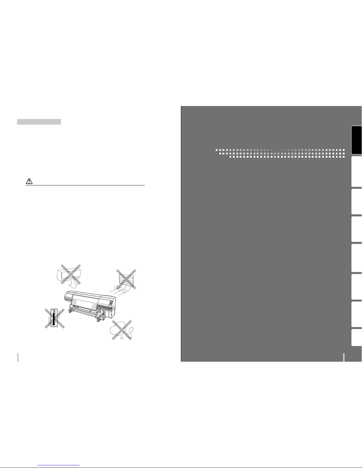
Do not install the printer in the following places.
z
Places near a re
z
Places exposed to direct sunlight
z
Places subject to vibration
z
Places with excessive dust
z
Places subject to extreme changes in temperature or humidity
z
Places near an air conditioner or a heater
z
Places where the printer may get wet
z
Places exposed to direct exhaust air from an air vent
z
Places near a diazo copier that may generate ammonia gas
z
Places with poor ventilation
z
Unstable places
Before printing
Loading the media Adjustment Maintenance
Advanced
operations
Troubleshooting Menu tree Appendix
Before printing
Page 13
24 25
Before printing Before printing
Appearance / Main components and their functions
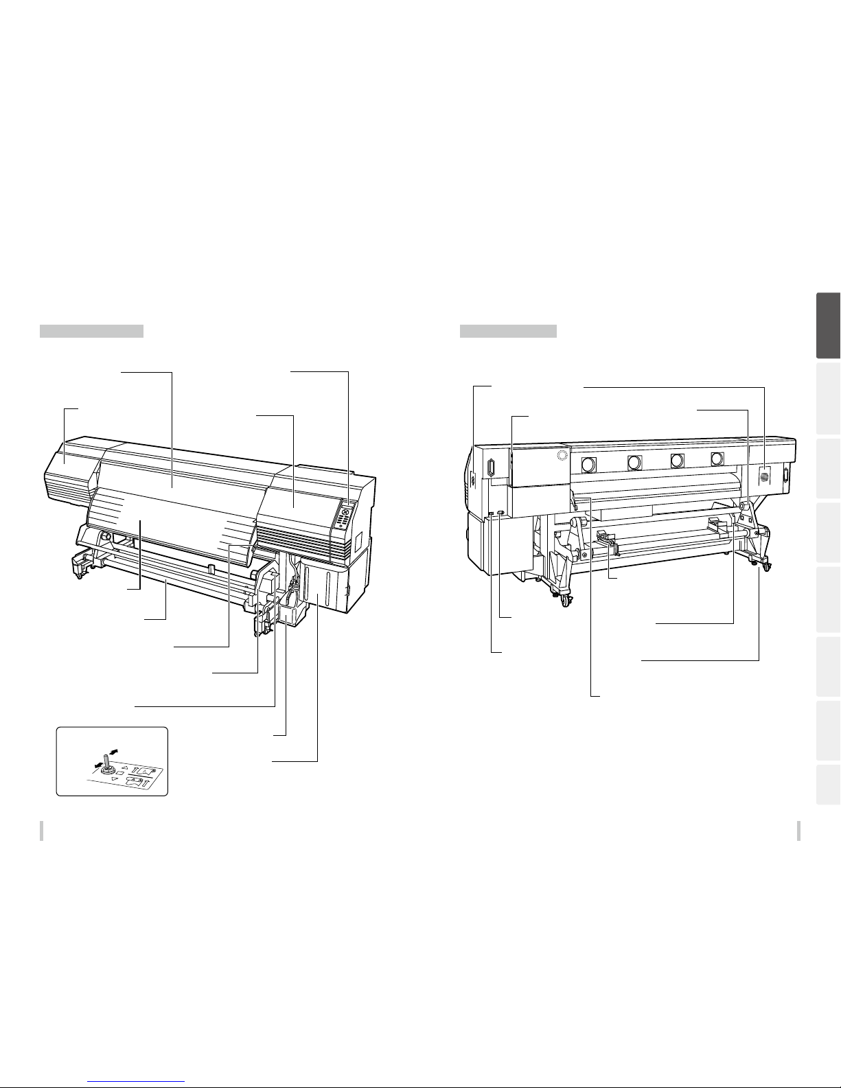
Printer front (take-up side)
Printer rear (supply side)
Before printing
Loading the media Adjustment Maintenance
Advanced
operations
Troubleshooting Menu tree Appendix
Waste ink bottle
Ink box
Open the cover to install the ink
cartridges.
Guide bar
Guides the media in loose mode.
Pressure roller lever
This lever fixes or releases the media.
Take-up direction switch
Sets the media take-up direc tion.
Take-up reel unit
Winds the printed media.
Output paper guide
Contains the after heater that dries ink.
Maintenance cover
Open to perform print head
maintenance.
Front cover
Must be closed during printing.
Capping cover
Opened when cleaning the capping
unit or the carriage.
Operation panel
Equipped with LEDs and LCD to display the
printer status, and keys to set functions .
Inner take-up
Winding o
Outer take-up
Pressure roller lever
A lever used to fixe or release the media.
Moves together with the pressure roller lever at the pr inter
front side.
Exhaust attachment (option)
Installation locations
Power inlet
Connect the power cable to
the power inlet.
Media stand
Temporarily supports the media durin g loading
and removal procedures.
Can be used also when moved to the TUR unit
side.
Media holder
To be installed at both ends of
the roll media.
Media jack
Lifts or lowers the media dur ing loading and removal
procedures.
Can be used also when moved to the TUR unit side.
Caster
Set the lock to OFF when moving the printer and set
the lock to ON when locking the printer.
USB connector
Used to connect the printer to a
computer.
Printer power switch
Page 14
26 27
Before printing Before printing
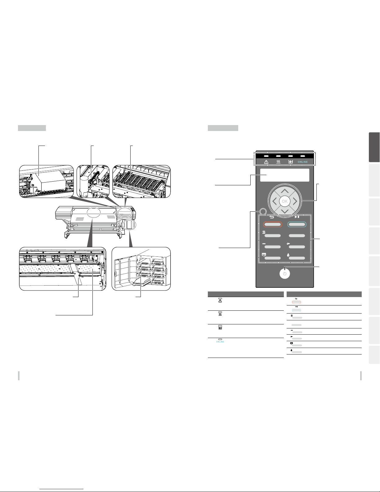
Printer interior
Operation panel
The keys, LEDs and LCD are placed on the printer's operation panel as shown below. In addition, the operation panel
is also equipped with a buzzer to draw attention in case an error occurs or an invalid key is pressed.
POWER
HEATER MENU
CANCEL
SET
ORIGIN
ONLINE
ADJUST
MAINTENANCE
NOZZLE PRINT PH.RECOVERY
LED
Error LED (Orange)
Indicates whether a n error has occurred.
ON: An error has occurre d.
Blink: Warning state .
OFF: Normal (no error)
Media heater LED
(Green)
Indicates the status o f the media heater.
- ON: The set tempera ture has been reached
- Blink: Currently hea ting
- OFF: Media heater is o
Ink LED (Green)
Indicates whether ink is remaining.
ON: Ink for all colors is p resent.
Blink: Ink near-en d (The level of any color is lo w.)
OFF: No ink.
ONLINE LED (Green)
Indicates the online, o ine, data reception, an d
pause status.
- ON: Online
- Blink (slowly): In pause
- Blink (fast): Data recept ion
- OFF: Oine
Keys
CANCEL
Cancels entered para meters or returns back to the up per
menu.
ONLINE
Switches between o nline and oine states, and pu ts the
printer in pause or resum es printing.
HEATER
Enters heater control me nu.
MENU
Used to display informat ion about the printer an d change
printer settings.
ADJUST
Used to enter the adjustm ent menu.
MAINTENANCE
Used to enter the maintenan ce menu.
NOZZLE PRINT
Used to perform a noz zle print.
PH.RECOVERY
Used to enter the cleaning m enu.
Before printing
Loading the media Adjustment Maintenance
Advanced
operations
Troubleshooting Menu tree Appendix
Carriage
Houses the print heads inside, and
prints image while moving over the
media.
Ink tray
Supports ink cartridges.
Media edge guards
Prevent print heads from being damaged by
deformed the media edges.
Platen
Transports the media.
The platen includes the suction fans an d the
printheater to dry the ink.
Wiping unit
Removes foreign substances on
the print head’s nozzle surface.
Capping unit
Prevents the print head’s nozzles
from drying.
Power switch
Used to turn on or off the power of th e
printe r.
Keys
Use these keys to operate the menu of
the printer.
Refer to the table below.
Up, Down, Left, Right keys
Used to select menu options, switch
between menus (selectio n, increasing/
decreasing values), etc.
OK key
Used to confirm the menu and
parameters.
LCD
It shows the status of the printer and
displays the menu window (2 rows, 20
characters).
Buzzer
Sounds when an error occurs or an
invalid key is pressed, and warns of daily
maintenance and when the print heads
are uncapped.
LED
ON, blinking and OFF indicate the
status of the printer.
Page 15
28 29
Before printing Before printing
To turn the printer on and o
The power supply must be 200 V.
CAUTI ON
Do not use any power cable oth er than the one supplied with the p rinter.
The supplied power cab le is for 200 V AC only. Note that the plug shap e diers from that for 100 V AC.
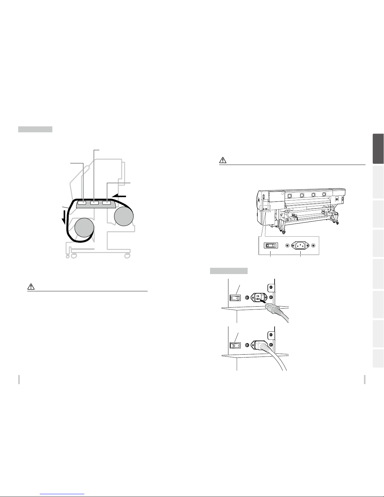
First turn the printer main power switch on, then use the power switch on the operation panel to turn the printer on
or o.
Supply side
Printer power switch Printer power inlet
Power-on procedure
1
Switch off ( O )
Conrm that the printer power switch at the
back of the printer is turned o (O). If on ( I ),
turn it o (O).
Plug one end of the supplied power cable
into the printer power inlet and the opposite
end into a power outlet.
2
Switch on ( | )
Turn on ( I ) the printer power switch at the
back of the printer.
Printer heater unit
The printer is equipped with three heaters for ink fusing and image quality stabilization.
• Print heater (front)
Penetrates ink into media to fuse the ink.
• Preheater (rear)
Preheats media.
• Afterheater (finishing)
Dries ink to stabilize print quality.
Media
* These three heaters are controlled independently.
Th e temperature o f the heaters can b e controlled fro m the operatio n panel, the RIP s oftware a nd Cp_
Manager.
WARNING
Do not touch these heater s to avoid burn as they become hot.
Before printing
Loading the media Adjustment Maintenance
Advanced
operations
Troubleshooting Menu tree Appendix
Page 16
30 31
Before printing Before printing
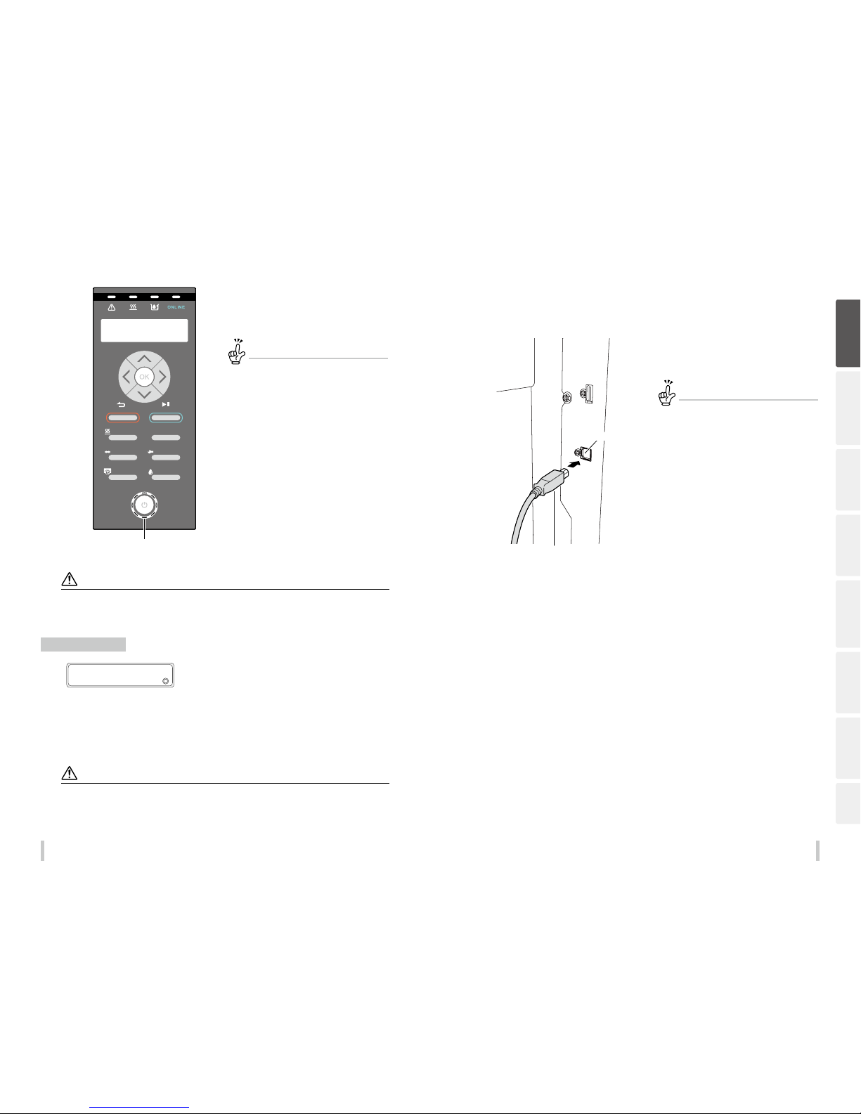
3
POWER
HEATER MENU
CANCEL
SET
ORIGIN
ONLINE
ADJUST
MAINTENANCE
NOZZLE PRINT PH.RECOVERY
LORD MEDIA
Power ON/OFF switch
Press the power switch on the operation
panel.
The printer executes a self-diagnostic test and displays the
message to the left on the operation panel.
If an error message appears...
To recover the error, refer to When an error
message is displayed .
If the POWER LED on the operatio n panel does
not light even when the printer and h eater power
switches at the rear of the printer an d the power
ON/OFF switch on the operation p anel are turned
on, the power supply may have a probl em.
CAUTI ON
Except for emergenc y, turn o the power while the messag e PRINTER READY is displayed. If the powe r is turned o when
the printer is displaying INITIALIZING... or CLEANIN G, the ink may dribble, the print h ead may be damaged, or saved
parameters may be lost .
Power-o procedure
1
>EDIT MEDIA PRESET S
2
SELECT PRESET NO.
To turn o the power of the printer, keep the
power switch on the operation panel pressed
for 2 seconds.
The message shown above is displayed on the LCD to indicate that the shutdown process is being executed. The power
turns off after the shutdown procedure is finished.
To keep the print head in good condition during shutdown, the fill cap operation (state where the cap is filled with ink)
is performed. To quickly turn off the power, press the power switch while holding the CANCEL key to skip the fill cap
operation and turn off the power. However, executing the fill cap operation is generally recommended.
Notes
After turning the power o , wait at least 5 seconds before tu rning it back on.
To keep the print heads in good condit ion, the printer perform a utomatically and periodic ally the ll cap operation whil e in
standby mode. It is reco mmended to keep on the power swi tch on the operation panel durin g this operation.
To connect the USB cable
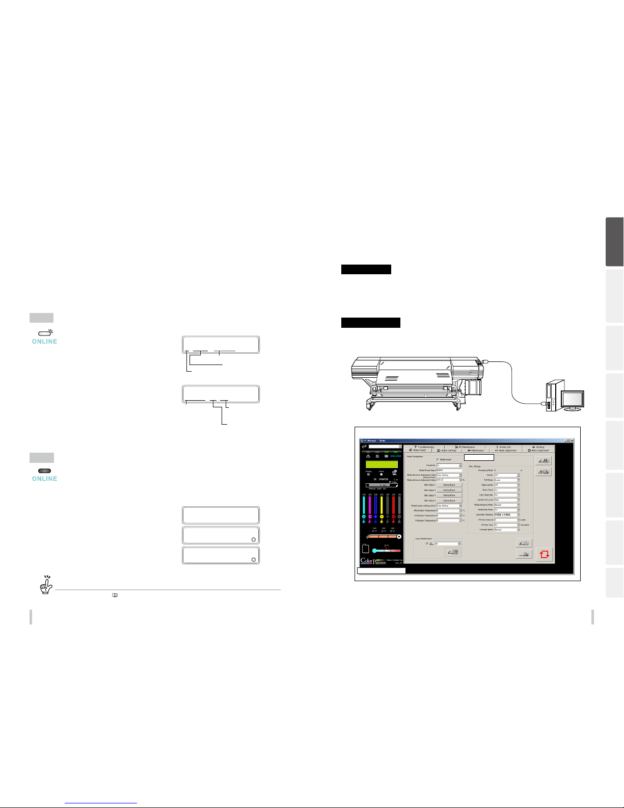
1
USB 2.0 cable (B-type connec tor)
USB connector
Connect the printer’s USB 2.0 cable to the
USB connector at the center of the printer
rea r.
Important!
Use the supplied USB 2.0 cable.
For the USB connection and relate d systems, use
hubs and cables suppor ting USB 2.0. Note that
normal operation canno t be guaranteed if the
hubs, cables, and the other r elated devices are not
USB-compliant.
Use a cable of 5 m or shorter. If the conne ction
length exceeds 5 m, use hubs to ex tend the
connection. The hub qua ntity must be ve or less
in total. Note that normal ope ration cannot be
guaranteed if the cable exce eds 5 m, or if the cable
connection exceeds 5 m wi thout hubs.
Before printing
Loading the media Adjustment Maintenance
Advanced
operations
Troubleshooting Menu tree Appendix
Page 17
32 33
Before printing Before printing
Online and oine
The printer operates in both online and oine states.
When the printer is in online:
- The printer prints the data sent from the computer’s Raster Image Process (RIP) software.
When the printer is in oine:
- The menu is operated with the operation panel keys.
The Online key switches between online and oine states.
When the MENU, ADJUST, MAINTENANCE, NOZZ LE PRINT, or PH.RECOV ERY key is pressed in online state, the
printer switched to oine to make menu operations possible.
Online
When the online LED is on, the printer is online.
Media of 1626 mm (64 inches) in width
Media name: PAPER
The number of the selected m edia: 01
PRINTER READY
01: PAPER / 1626mm
Online state (idle mod e) display
When the online LED blinks, the printer is printing.
Print direction
BI: Bidirectional
UNI: Unidirectional
Density
ND: Normal density
HD: High density
Print mode
DRAFT
FAST PRODUCTION
PRODUCTION
STANDARD
QUALIT Y
HIGH QUALITY
MAX QUA LITY
PRINTING
NORMAL ND BI
Online state (print mod e) display
Oine
When the online LED is o, the printer is oine.
The message displayed on the panel when the printer switches to oine diers depending on the key that has been pressed.
When the ONLINE key is pressed:
OFFLINE
When the ADJUST key is presse d:
ADJUST
2
MEDIA ADVANCE
When the PH.RECOV ERY key is pressed:
PH RECOVERY
2
NORMAL
When an operator call error is displayed...
When an operator call erro r (
pa ge 173
) is displayed, the printer may not ope rate even if the CANCEL key is pressed.
CP_Manager
The Printer supports the CP_Manager software which provides a general view of the printer status. The following
operations can be performed with CP_Manager™.
Panel operations
- Display the printer status
- Create media preset, input adjustment values
- Execute nozzle print, adjustment patterns print
- Maintenance time notice, maintenance operation
Additional functions
- Display operation guidance
- Display the instruction manual (PDF)
Printer
Computer
USB interfa ce
Printer status display
Media preset
CP_Manager display example
Install CP_Manager™ using the CD-ROM supplied with the printer.
Before printing
Loading the media Adjustment Maintenance
Advanced
operations
Troubleshooting Menu tree Appendix
Page 18

3534
Before printing
Supported media
Vinyl
Vinyl is media with PVC-material surface. As generally vinyl is adhesive-backed, by removing the release paper on
the back you can stick the media easily. Depending on its gloss grade, the vinyl is classied into three categories:
glossy vinyl (with high gloss), matte vinyl (with no gloss), and semi-glossy vinyl (with medium gloss).
When the media is applied on some prints, a gray adhesive-backed vinyl is eective to avoid the prints seen through
the top media.
For backlit purpose application, the PVC material surface is sometimes transparent or translucent.
Banner
Banner is polyester fiber cloth media with both sides coated with synthetic plastic film such as PVC. As the
banner is water- and tear-resistant, it is used for tent canvas, construction wrap sheets, and inkjet-printed banner
advertisements.
Depending on its gloss grade, the banner is classied into three categories: glossy banner (with high gloss), matte
banner (with no gloss), and semi-glossy banner (with medium gloss).
Mesh banner (with liner)
Mesh banner is perforated banner media reinforced with mesh grid. As its open structure allows wind to permeate,
the mesh banner is wind- and tear-resistant, and withstands heavy wind.
Depending on whether liner (ink absorbing back sheet) is present, the mesh banner is classied into two categories:
backed and unbacked.
Backlit banner (FF)
Backlit banner exible face (FF) is translucent, that is, semi-transparent banner media. Thanks to that, it is used for
backlit signs inside light boxes.
Compared with an acrylic sign, the backlit banner is lightweight and easy to handle, wind- and tear-resistant, and
highly safe. it can withstand strong wind pressure.
Solvent printing coated paper
Solvent printing coated paper is media with the printing surface coated, on which solvent ink is cured vividly. Its
thickness depends on the product type.
When the media is applied on some prints, a blue back type is eective to avoid the prints seen through the top
media.
Before printing
Loading the media
Adjustment Maintenance
Advanced
operations
Troubleshooting Menu tree Appendix
Loading the media
Page 19
36 37
Loading the media Loading the media
Loading the media on the printer
Procedure to load roll media
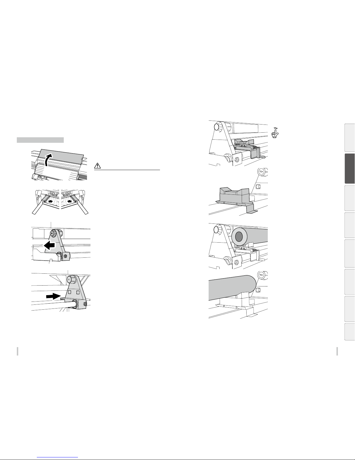
1
Open the front cover and place the right and
left edge guards at each extremity of the
platen. Close the front cover.
Notes
The media edge guards a re put aside to avoid any
contacts with the rol l ends when loading the media .
When using a media whos e end is attached to the roll
tube with adhesive, this adhesive may adhere to the
paper guide or the plate n. In this case, be sure to remove
all adhesive before loading the new media.
2
Move the left media holder fully to the left.
3
Move the right media holder fully to the right.
4
Install the media jack and media stand.
The media will be loade d from the left side, so
install the media lifte r to the left side and the media
stand to the right side.
Install them considering the m edia width.
5
Load the media onto the media jack and
media stand.
Before printing
Loading the media
Adjustment Maintenance
Advanced
operations
Troubleshooting Menu tree Appendix
Page 20
38 39
Loading the media Loading the media
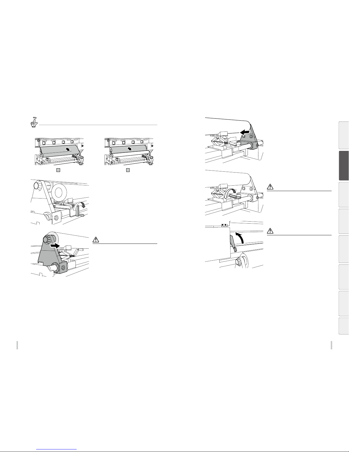
Media orientation
<When the surface to be printed on is
at the outer side of the roll>
:printingsurface :printingsurface
<When the surface to be printed on is
at the inner side of the roll>
6
Turn the media jack’s handle clockwise to
raise the media until the roll tube is aligned
with the media holder.
7
Insert the left media holder into the roll tube.
Notes
Pay attention not to unwind the m edia or damage the
ends of the roll media wh en inserting it into the medi a
holder.
Insert as far as it goes to s ecure the roll tube to the
media holder.
8
Turn the media jack’s handle counterclockwise to remove the jack. Then install it
to the right side of the roll.
9
Adjust the roll level using the media jack and
insert the right media holder into the roll the
same way as you did for the left side.
10
Turn the media jack’s handle counterclockwise to lower and remove the jack. Then
put the media jack and the media stand away.
Note
If you leave the media jack or th e media stand in place
under the roll media, t he media may curl or be damaged
when back feeding it . Be sure to put them away.
11
Lift the pressure roller lever.
Note
The pressure roller leve r has three positions (low,
medium, and high). Always put the l ever in the highest
position when loading the media.
Before printing
Loading the media
Adjustment Maintenance
Advanced
operations
Troubleshooting Menu tree Appendix
Page 21
40 41
Loading the media Loading the media
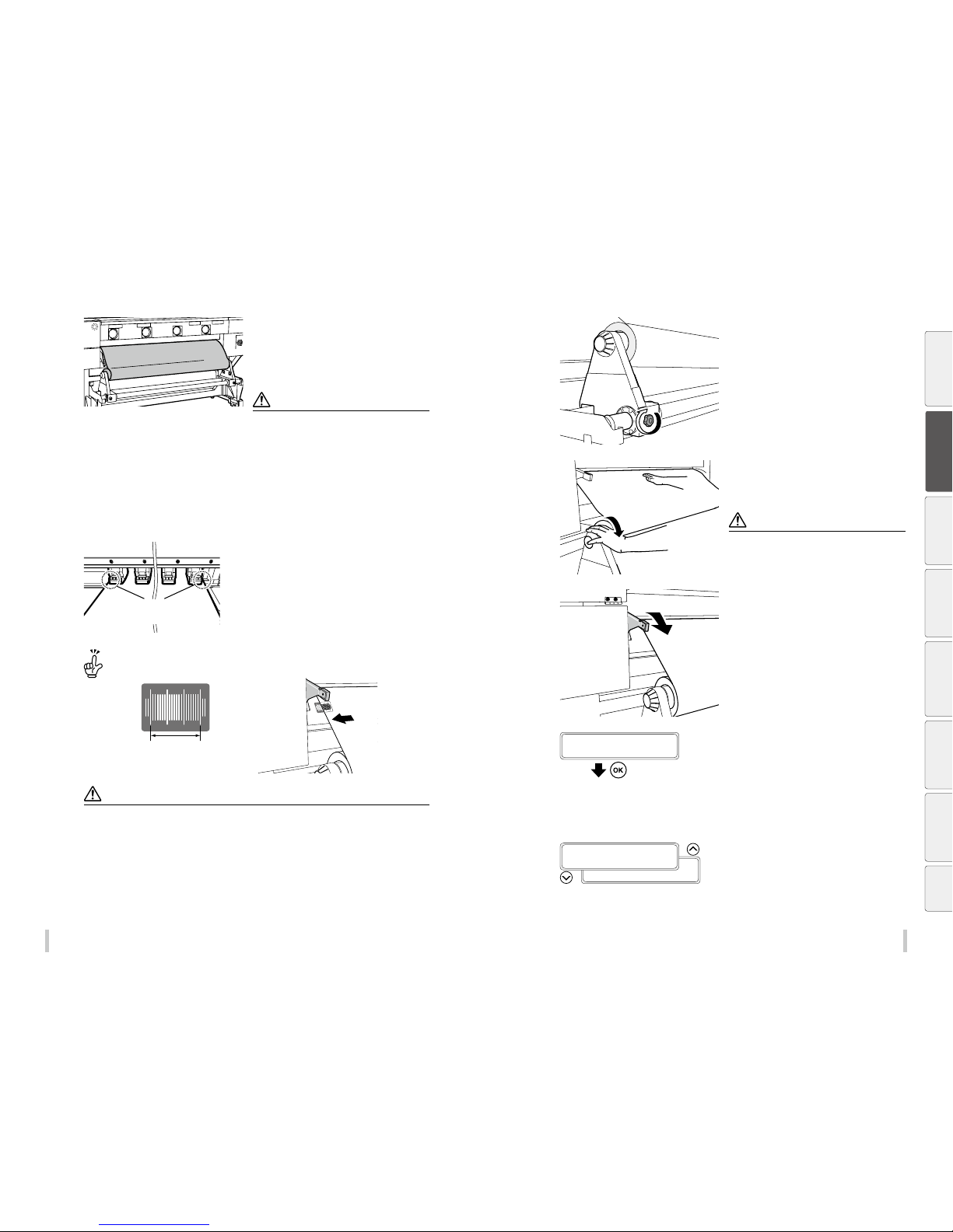
12
Pass the media between the pressure roller
and the grit roller. When you hear a beep
sound, feed the media 80 cm further.
The printer emits a sound when the media
leading edge comes out from the front cover.
Notes
Depending on the envir onment, the media may stick to
the paper guide and have dic ulty to advance. In such
a case, hold both ends of t he roll to separate the media
from the paper guide an d then feed the media.
If the leading edge of th e media curls up or down, it may
get caught inside the pri nter and may not be installed
properly. Do not use heavily c urled media.
Make sure that the leading e dge of the media does
not touch the front cover. If the medi a forms a curve,
straighten it before th e installation.
Check that the media edg e guards are not caught under
the media.
13
Place the media so that the pressure roller
evenly touches the media.
Move the media holders so that the media
edges are evenly placed under the pressure
roller.
Note the position of the media e dges on the sticker gradations to facil itate position adjustment the nex t time you
load the media.
Adjust the media position so that the
edge is place above the gradations.
Note
Always move the media holder s to adjust the position. Moving o nly the media may cause it to skew.
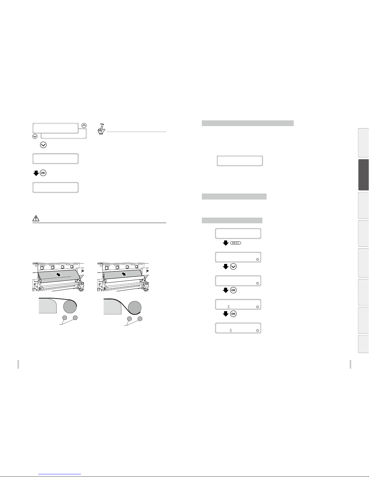
14
Turn the knob screws on both media holders
to secure them.
15
While keeping your hand on the media to
straighten it, turn the ange to wind the
media until only 20 cm comes out from the
front cover.
Note
Do not try to forcibly a lign the media with the gradati ons
lines but install the me dia parallel to the roll.
16
Put the pressure roller lever to the lowest
position.
From here, continue the procedure following
the messages displayed on the LCD screen.
17
EDGE GUARDS POSITION
OK?
Open the front cover and place both edge
guards on the media edges. Place the media
edges in the notches on the edge guards.
Then close the front cover.
Check that the edge guards do not go under the media,
or that the media advance smoothly in case of particularly
thick media.
Check visually that the media edge guards are correctly
placed then press the OK key.
18
SELECT MEDIA T YPE
MEDIA TYPE: X XX
SELECT MEDIA T YPE
MEDIA TYPE: PAPER
Select the media type.
Select a registered media type using the Up and Down
keys, then press the OK key.
Before printing
Loading the media
Adjustment Maintenance
Advanced
operations
Troubleshooting Menu tree Appendix
Page 22
42 43
Loading the media Loading the media
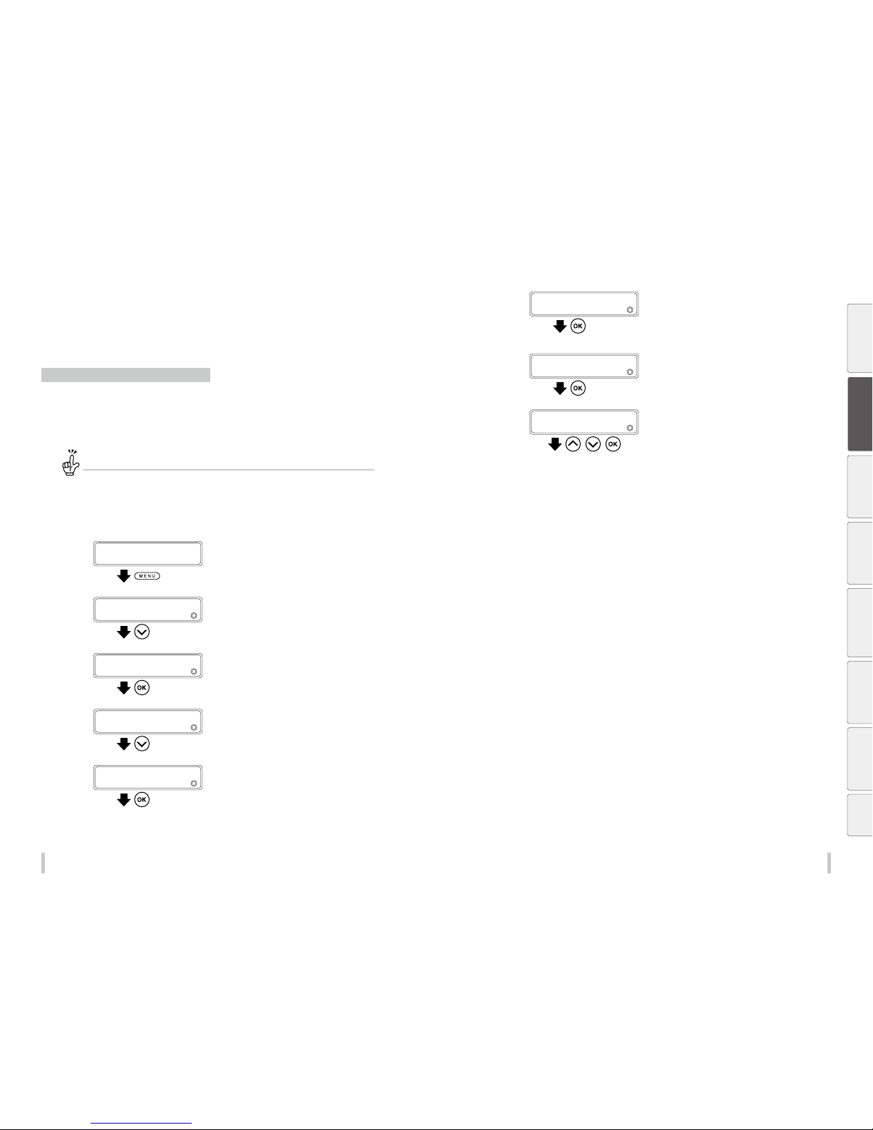
SELECT MEDIA T YPE
MEDIA TYPE: X XX
SELECT MEDIA T YPE
MEDIA TYPE: PAPER
• • •
(Display the media presets)
SELECT MEDIA T YPE
CREATE NEW PRESET
(Enter the media preset menu)
To create a new media preset
At the end of the media preset list , CREATE NEW
PRESET is displayed.
Press the OK key to enter the media registra tion
menu.
The procedure to create a preset is t he same as in
the MEDIA REG menu.
Press the Left key to exit the media re gistration
menu and return to the media t ype selection menu.
Press the CANCEL key to cancel the entered
parameters.
19
CHECKING MD EDGES
PLEASE WAIT
The media loading operation starts
automatically.
- When the operation completes successfully, the printer
returns to the online or offline state.
- If the operation fails, an error message is displayed.
In this case, perform the procedure again starting from step
1
.
Notes
After the media has be en installed, check that t he media does no enter the gap fo rmed by the cutter blade (option) or
that it is not caught in the med ia clips (options). Also check that the med ia evenly contacts the platen a nd that it does
not wrinkle.
When using tarpaulin o r other high basis weight media , pay attention not to let a media sla ck of more than 15 cm
form on the roll side. The we ight of the media slack may make the me dia roll rotate and unwind.
When back feeding mor e than 30 cm or media, do not do it in a sing le operation but back feed the m edia slowly while
removing the slack by rota ting the media roll manually.
<When the surface to be printed on is
at the outer side of the roll>
<When the surface to be printed on is
at the inner side of the roll>
Rear paper guide
Feed unit tubes
Roll media
Rear paper guide
Feed unit tubes
Roll media
Replacing the media when the end of the roll is reached
When there is no more media on the roll, the printer detects it automatically and displays a message.
However, note that with some media types, the printer may not be able to automatically detect the end of the roll. If
printing continues when there is no more media, the printer may get dirty or malfunction. Be sure to check visually
the remaining length of media.
1
LIFT THE LEVER A ND
LOAD THE MEDIA
A message is displayed on the LCD screen.
2
Replace the media following the Procedure to remove the roll media and the Procedure
to load the roll media.
Replacing the media after a media jam
Refer to How to clear a media jam on page 171.
Setting the media remaining length
1
PRINTER READY
01: PAP ER/1626 mm
Press the MENU key.
2
MENU
2INFORMATION
Press the Down key to select REMAINING
MEDIA.
3
MENU
2
REMAINING MEDIA
Press the OK key.
4
>REMAINING MEDIA
2
***g050m
Set the remaining media length and press the
OK key.
>REMAINING MEDIA
2
050g050m
Before printing
Loading the media
Adjustment Maintenance
Advanced
operations
Troubleshooting Menu tree Appendix
Page 23
44 45
Loading the media Loading the media
Setting the media on the
take-up reel unit
Tension and loose mode setting procedure
Two modes, tension mode or loose mode, can be selected for take-up reel unit (TUR) operation.
Usually, select loose mode when printing on vinyl (adhesive-backed) media.
When printing on tarpaulin or other media that does not slide well, use the tension mode if the media tends to shift
on the TUR unit.
Inner take-up direction cannot be used in loose mode.
Use the inner take-up dire ction in tension mode, or outer take -up direction.
Tension and loose mode setting procedure
Set the mode using TUR MODE in the EDIT MEDIA PRESETS menu.
1
PRINTER READY
01: PAP ER/1626 mm
Press the MENU key.
2
MENU
2
INFORMATION
Press the Down key to select EDIT MEDIA
PRESETS.
3
MENU
2
EDIT MEDIA PRESET S
Press the OK key.
4
>EDIT MEDIA PRESET S
2
SELECT MEDIA
Press the Down key to select MISC SETTINGS.
5
>EDIT MEDIA PRESET S
2
MISC SETTI NGS
Press the OK key.
6
>>MISC SETTINGS
2
REMAINING MEDIA
Press the Down key to select TUR MODE.
7
>>MISC SETTINGS
2
TUR MODE
Press the OK key.
8
>>>TUR MO DE
2
*LOOSE
, ,
Select LOOSE or TENSION using the Up an d
Down keys, and then press the OK key.
Before printing
Loading the media
Adjustment Maintenance
Advanced
operations
Troubleshooting Menu tree Appendix
Page 24
46 47
Loading the media Loading the media
In loose mode
Loose mode is recommended for vinyl and solvent printing coated paper media.
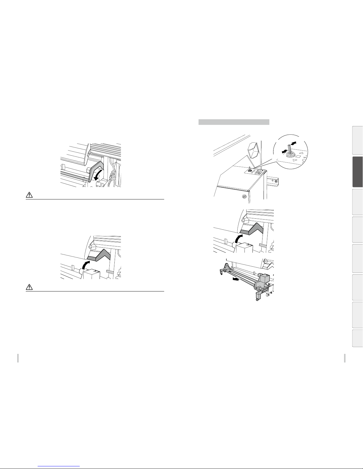
Remove the guide bar from the standby position and put it in the usage position by pulling the bar toward
you.
Note
Taking up the media in loose mod e with the guide bar in the standby p osition may cause the media to shif t.
Do not put your hand on the guid e bar. Doing so may damage the guide bar or you m ay be injured by the guide bar falling .
In tension mode
Tension mode is recommended for tarpaulin media.
Leave the guide bar in the standby position.
Note
Taking up the media in tension mo de with the guide bar in the usage p osition may cause the media to shif t.
Procedure to set the media on the TUR unit
1
Put the take-up direction switch installed on the right media holder in the o position.
Inner take-up
Winding off
Outer take-up
2
Move the guide bar to the standby position.
3
Hold the front pipe of the TUR unit by the
center and pull the TUR unit toward you.
Before printing
Loading the media
Adjustment Maintenance
Advanced
operations
Troubleshooting Menu tree Appendix
Page 25
48 49
Loading the media Loading the media
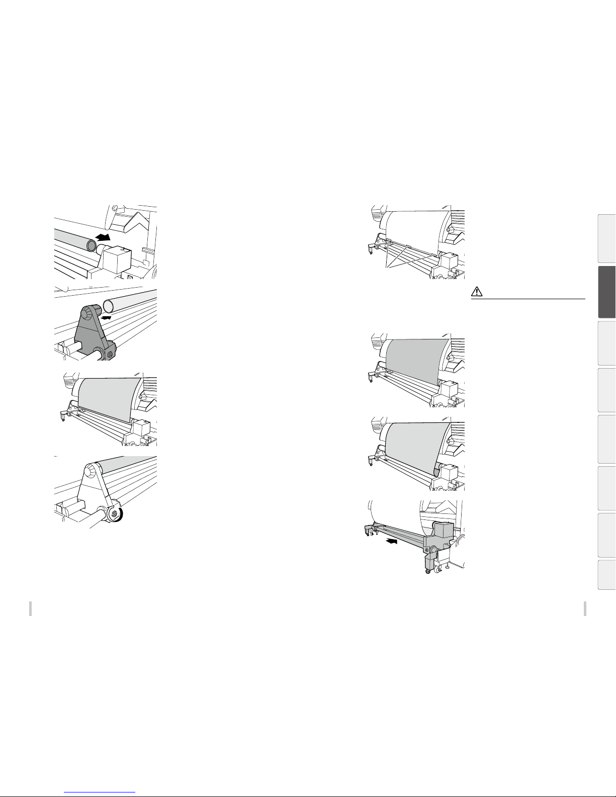
4
Insert the right ange into one end of a paper
tube.
5
Move the left ange and insert it into the
other end of the paper tube.
6
Tighten the knob screw on the left ange to
secure the position.
7
Feed the media until the leading edge
reaches the paper tube.
8
Adhesive tape
Maintain the media stretched and attach it to
the paper tube with some adhesive tape.
Notes
Attach the media with th ree pieces of tape, one at the
center and one at both the righ t and left edges.
Pay attention to keep the medi a straight as it may skew
otherwise.
9
Rotate the tube one turn to prevent the
media from detaching from the tube.
To take up the media, either rotate the flange manually or
use the take-up reel switch while feeding the media.
Switch between the on and off positions of the take-up reel
switch to wind the adequate length of media.
10
Feed the media a little more to create a slack.
11
When the TUR unit is set to outer take-up
direction, push the TUR unit under the printer
as far as it goes.
When the TUR unit is set to inner take-up
direction, leave the TUR unit in its current
pulled out position.
Before printing
Loading the media
Adjustment Maintenance
Advanced
operations
Troubleshooting Menu tree Appendix
Page 26
50 51
Loading the media Loading the media
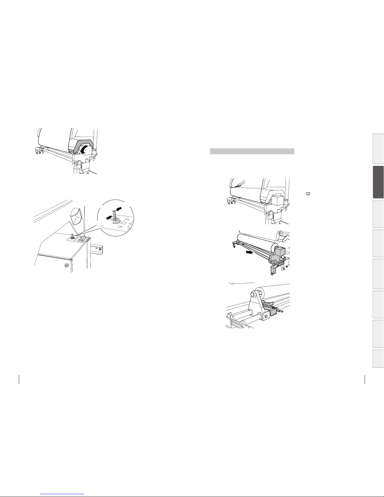
12
If loose mode is selected, place the guide bar
in the usage position.
13
Set the take-up direction switch.
In loose mode, always select outer take-up direction .
Refer to the figure below to set the switch.
Inner take-up
Winding off
Outer take-up
Removing the media
Procedure to remove the roll media (output side)
1
Feed the media until all the printed part that
will be used has passed the output paper
guide.
2
Cut the media at the edge of the output
paper guide.
If you use the optional cutter unit, refer to Cutting the
media on
page 55.
3
Place the guide bar in the standby position
and pull the TUR unit toward you.
Hold the front pipe of the TUR unit and p ull it toward you.
4
Install the media jack at the left side.
Before printing
Loading the media
Adjustment Maintenance
Advanced
operations
Troubleshooting Menu tree Appendix
Page 27
52 53
Loading the media Loading the media
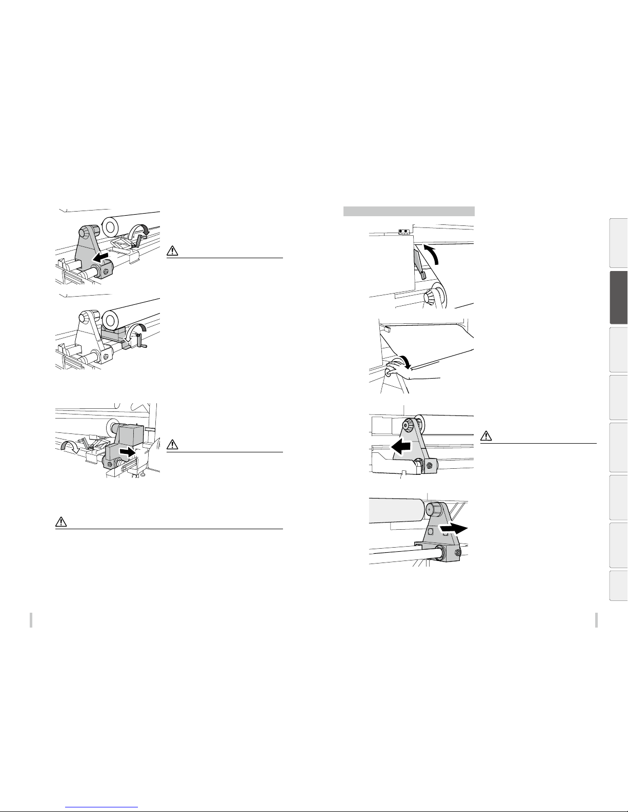
5
①
②
Remove the left side rst.
1 Turn the media jack’s handle clockwise to raise the
media lifter to the level of the media.
2 When the jack supports the media, slide the left media
holder to remove it from the media roll.
Note
Do not raise the media jac k too high when the media is
still installed on the m edia holder. Doing so may damage
the media holder or the m edia jack.
6
Place the left side of the media on the media
stand.
1 Install the media s tand next to the jack.
2 Turn the media jack’s handle counter-clockwise to lower
the media until it is supported by the stand.
7
Slide the media jack and install it to the right
side.
8
①
②
Next, remove the right side.
1 Turn the media jack’s handle clockwise to raise the
media lifter to the level of the media.
2 When the jack supports the media, slide the right media
holder to remove it from the media roll.
Note
Do not raise the media jac k too high when the media is
still installed on the m edia holder. Doing so may damage
the media holder or the m edia jack.
9
Turn the media jack’s handle counterclockwise to lower the media, and then
remove the media.
Notes
The media is heavy. Always use t wo or more people when handl ing roll media to prevent injur y, such as when the
media fall over someone ’s feet. Also, if you feel that the med ia is too heavy, take measures to handle i t properly such
as increasing the number of people carrying out the operation. Incorrect handling of the media may lead to personal
injury.
To prevent injuries, use a dolly equi pped with a lifter (recommen ded dolly) when loading, rem oving or replacing the
media.
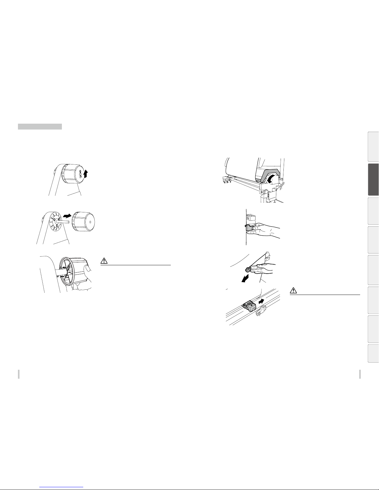
Procedure to remove the roll media (feed side)
1
Lift the pressure roller lever.
2
Rotate the ange to rewind the media.
3
Move both the right and left anges to
remove them from the tube, and then remove
the media.
Notes
If a lot of media remains a nd the roll is heavy, use tools
to help you and remove the medi a using the loading
procedure in the revers e order.
Be careful that the med ia does not fall when removing
the media holders fr om the roll. Workers may be injured
if their hands get caught u nder the media or if the media
falls on their feet.
Before printing
Loading the media
Adjustment Maintenance
Advanced
operations
Troubleshooting Menu tree Appendix
Page 28
54 55
Loading the media Loading the media
When using 2-inch tubes
Optional 2-inch anges can be installed to use roll media with a tube of 2 inches in diameter.
You can use this type of roll media on both the feeding side and TUR side.
Use the procedure below to install 2-inch anges.
1
Remove the R-pin from the 3-inch ange, and
then remove the ange.
2
Install the 2-in ange.
Notes
Align the pin and the groove in th e ange when
installing the new ang e.
The new ange may not slide sm oothly around the shaft .
Make sure the shaft is inse rted completely in the an ge.
Pay attention not to lose the R- pin or the pin.
3
Install the R-pin.
Cutting the media
The following explains the procedure to cut the media using the optional cutter unit.
1
Place the guide bar in the usage position.
2
Fix both media edges using media clips.
3
Move the media cutter blade to cut the
media.
Arrow mark
Note
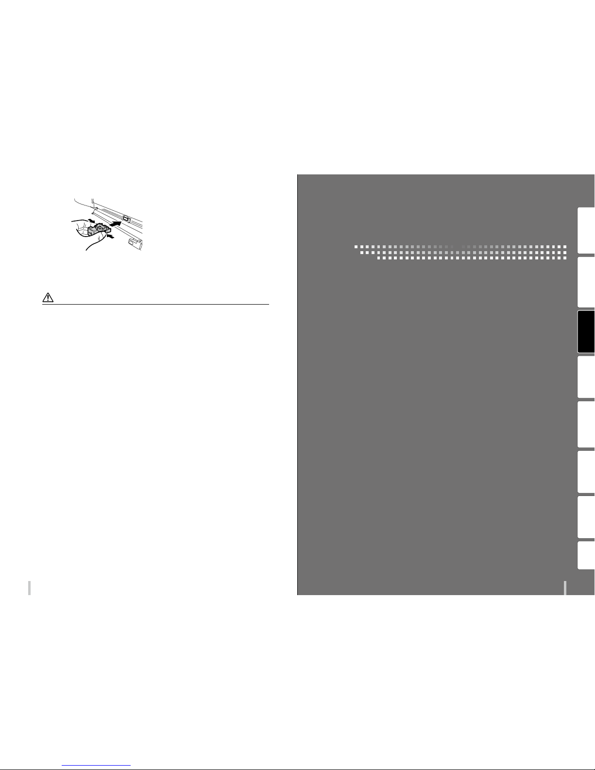
An arrow mark ( g ) is engraved on the media cut ter
blade.
The cutter cuts only in t he direction of the arrow. If the
arrow is not oriented in the cut ting direction, change t he
blade orientation following the procedure below.
Before printing
Loading the media
Adjustment Maintenance
Advanced
operations
Troubleshooting Menu tree Appendix
Page 29
5756
Loading the media
1
Grasp both sides of the cutter blade, push
the two hooks securing the blade, and then
remove the blade with the hooks released.
2
Reverse the orientation of the blade and
reinstall it.
Notes
If the media cutter ge ts stuck while cutting, re turn the cutter blade to the si de, remove curls or other causes o f the problem,
and then cut the media agai n by slowly moving the media cut ter blade. Do not forcibly cut th e media otherwise the bla de
may be damaged and lose its c utting performance.
Pay attention not to drop the me dia cutter blade. If it falls t he blade may be damaged and lose it s cutting performan ce.
Handle the cutter bla de with care.
It may be impossible for the c utter blade to cut thick media o r cloth. In such cases, use a pair o f scissors or other adequate
means. Forcibly cutt ing thick media may damage the med ia cutter blade and degrad e its cutting performa nce.
Before printing Loading the media
Adjustment
Maintenance
Advanced
operations
Troubleshooting Menu tree Appendix
Adjustment
Page 30
58 59
Adjustme nt Adjustme nt
Before making adjustment
Make adjustments to maximize the print quality.
Before starting the adjustment, turn on the force heating function on the printer for 30 minutes or more.
Correct adjustment is not possible if the printer is not suciently warmed.
Always make print adjustment after installing a new media or changing the print mode.
Two types of adjustment are available: Media advance adjustment and bidirectional adjustment.
You can select automatic print adjustment and manual print adjustment for each type.
Automatic print adjustment Manual print adjustment
Media advance adjustment
Adjust the media feeding
page 59 page 62
Bidirectional adjustment
Adjust the ink output position during bidirectional
printing
page 66 page 69
Adjustment methods
Adjusting media feeding: Media advance adjustment
The media feeding operation can be adjusted depending on media characteristics, such as thickness, rigidness, and
smoothness of the surface.
To maintain a high print quality, perform media advance adjustment and set the most suitable media advance
adjustment value.
What is the timing to perform media advance adjustment?
When one of the following pa rameters has changed.
- The media has been change d
- The print mode has been cha nged
- The position of the pressure ro ller lever has been changed
- The TUR unit usage set ting or TUR mode (loose or tension) has be en changed
- The media advance mode ha s been changed
- The suction fan set ting (low, medium, high) has been changed
When the media advance adjus tment value is incorrect.
When the media advance adjus tment value is incorrect, band ing (horizontal bands) appears per iodically on the
printout.
Two modes are available to adjust media advance: automatic print adjustment and manual print adjustment.
With automatic print adjustment, the printer prints an adjustment pattern, check the result with sensors, and set a
media advance adjustment value automatically.
With manual print adjustment, the printer prints an adjustment pattern, then the user selects visually a media
advance adjustment value and set the value on the printer.
How to dierentiate between automatic and manual print adjustment
Automatic print adjustment is reco mmended for the following users .
- Users who do not have much exper ience with the printer
- Users who nd manual print adjus tment dicult
- Users who want nish adjustment qu ickly
* Automatic print adjustment may not b e available depending on the media t ype. If automatic print adjustm ent
does not improve the print qualit y, use manual print adjustment.
Manual print adjustment is recom mended for the following users .
- Users who needs the best p rint quality
Automatic print adjustment
<Worko w>
STEP1 STEP2
Completed
Select the print mode
Execute automatic print
adjustment
i
If the print quality has not been improved
Perform manual print adjustment ( page 62)
Before printing Loading the media
Adjustment
Maintenance
Advanced
operations
Troubleshooting Menu tree Appendix
Page 31
60 61
Adjustme nt Adjustme nt
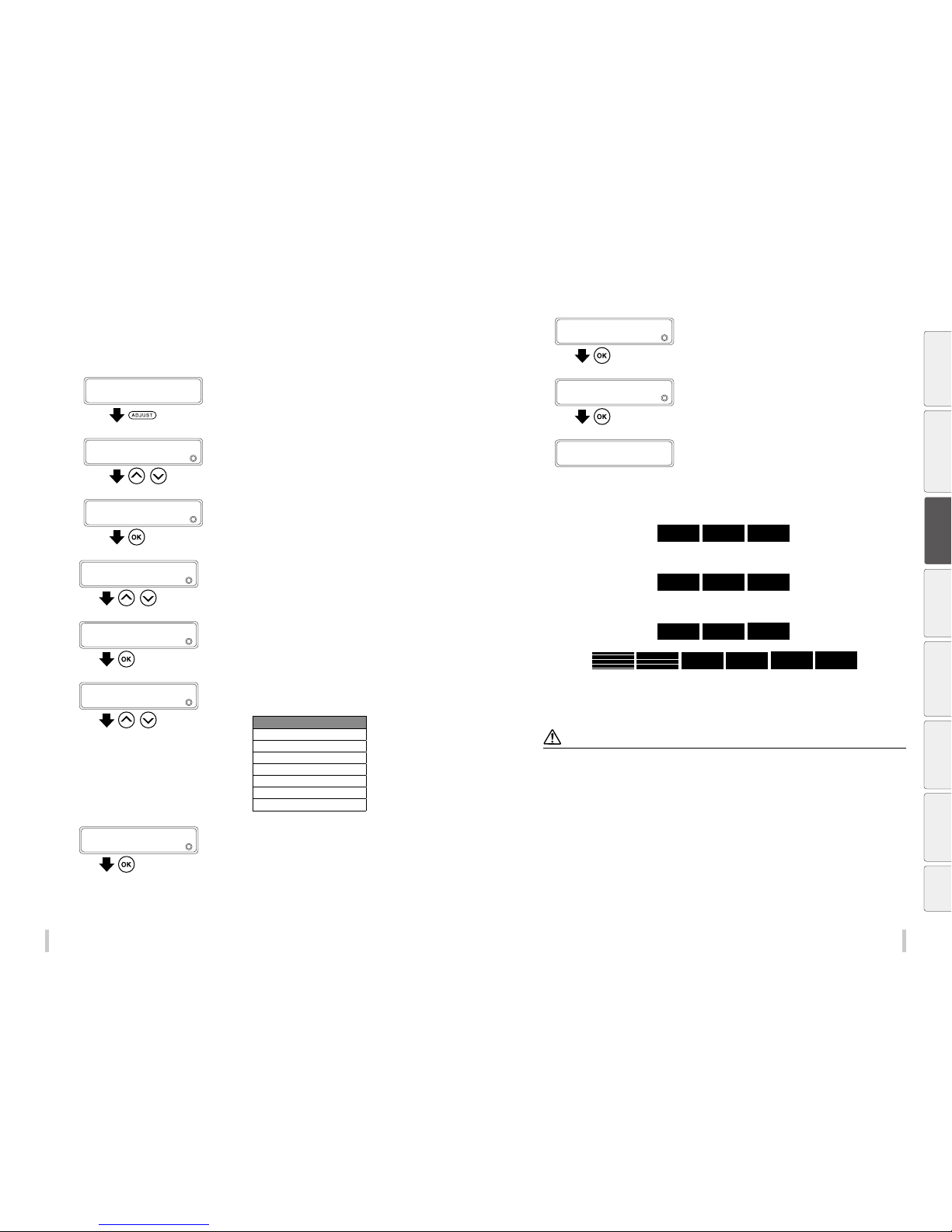
<Procedure>
1
Load the media.
Load the media in the same conditions as normal printing.
2
PRINTER READY
01: PAPER / 1626mm
Press the ADJUST key.
3
ADJUST
2
MEDIA ADVANCE
,
Press the Up and Down keys to select MEDIA
ADVANCE.
4
ADJUST
2
MEDIA ADVANCE
Press the OK key.
5
>MEDIA ADVANCE
2
MEDIA ADVANCE AUTO
,
Press the Up and Down keys to select MEDIA
ADVANCE AUTO.
6
>MEDIA ADVANCE
2
MEDIA ADVANCE AUTO
Press the OK key.
7
>>MEDIA ADVANCE AUTO
2
DRAFT
,
Press the Up and Down keys to select the
print mode.
Print mode
DRAFT
FAST PRODUCTION
PRODUCTION
STANDARD
QUALI TY
HIGH QUALITY
MAX QUALITY
8
>>MEDIA ADVANCE AUTO
2
DRAFT
Press the OK key.
9
>>MEDIA ADVANCE AUTO
2
EXECUTE
Press the OK key.
10
>>>DR AFT
PRINT OK?
Press the OK key to execute media advance
adjustment.
>>>DR AFT
EXECUTING
The printer prints the media advance adjustment pattern
and check the result with its sensors.
After the results have been checked, the printer
automatically set the media advance adjustment value. The
procedure is complete.
During this procedure, the printer prints and checks patterns similar to those shown below.
11
If the print quality has not been improved, perform manual print adjustment.
Note
The printer cannot set a co rrect adjustment value thr ough automatic print adjustme nt in the following cases. In suc h cases,
improve the conditions or pe rform manual print adjustm ent.
The automatic print ad justment determines mech anically the adjustment value , so absolute precision of the s etting cannot
be guaranteed.
- The media used makes the c heck via sensors impossib le.
<Examples>
- Transparent or colored media
- Media with a rough sur face
- Media with an extre mely high or low degree of re ection
- Media on which the pat tern cannot be printed prope rly, such as when the ink tends to bleed
- The media surface is so iled with dust, ink, ng er marks, etc.
- A gap tends to form betwe en the platen and the media
- Lots of nozzles are cl ogged
- The media heater tempe ratures are not suitable
- The environmental luminosity is too strong
Before printing Loading the media
Adjustment
Maintenance
Advanced
operations
Troubleshooting Menu tree Appendix
Page 32
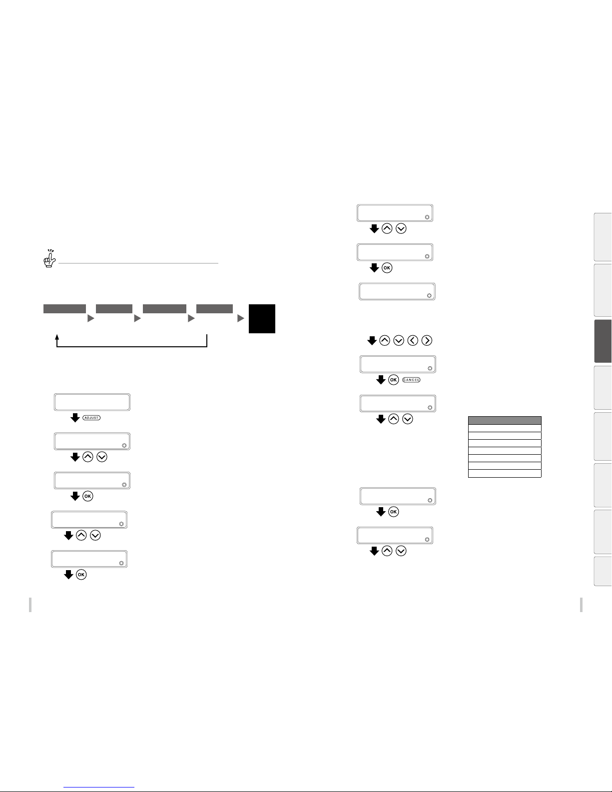
62 63
Adjustme nt Adjustme nt
Manual print adjustment
Through manual adjustment, you can choose between 1 pattern or 3 patterns to be printed.
With 1 pattern, the printer prints the media advance adjustment pattern with the set adjustment value.
With 3 patterns, the printer prints three media advance adjustment patterns, one with the set adjustment value, one
with the set adjustment value +0.2%, and one with the set adjustment value -0.2%.
TIP:
It is recommended to use 3 pat terns if you have no idea of a suitable for medi a advance
adjustment.
<Worko w>
STEP1 STEP2 ST EP3 STEP4
Completed
Enter the
media advance
adjustment value.
Select the print
mode.
Print the
media advance
adjustment pattern.
Check visually
the printed
pattern.
Media correctly aligned
Media misaligned
<Procedure>
1
Load the media.
Load the media in the same conditions as normal printing.
2
PRINTER READY
01: PAPER / 1626mm
Press the ADJUST key.
3
ADJUST
2
MEDIA ADVANCE
,
Press the Up and Down keys to select MEDIA
ADVANCE.
4
ADJUST
2
MEDIA ADVANCE
Press the OK key.
5
>MEDIA ADVANCE
2
MEDIA ADVANCE AUTO
,
Press the Up and Down keys to select MEDIA
ADV MANUAL.
6
>MEDIA ADVANCE
2
MEDIA ADV MANUAL
Press the OK key.
7
>>MEDIA ADV MANUAL
2
MEDIA ADV VALUE
,
Press the Up and Down keys to select MEDIA
ADV VA LUE.
8
>>MEDIA ADV MANUAL
2
MEDIA ADV VALUE
Press the OK key.
9
*: Registration mark (A registration mark * is displaye d if the
media preset is registered)
XXX. XX: Media advance adjustment value currently set
YYY. YY: Entered media advance adjus tment value
(Setting range 97.00 to 106.00%)
>>>MEDIA ADV VALUE
2
*XXX.XXgYYY.YY%
, , ,
Press the Right and Left keys to select the
digit, and press the Up and Down keys to
select a value for media adjustment.
10
>>>MEDIA ADV VALUE
2
*XXX.XXgYYY.YY%
,
Pres the OK key to conrm the entered value,
and press the CANCEL key to exit MEDIA A DV
VALUE .
11
>>MEDIA ADV MANUAL
2
DRAFT
,
Press the Up and Down keys to select a print
mode.
Print mode
DRAFT
FAST PRODUCTION
PRODUCTION
STANDARD
QUALI TY
HIGH QUALITY
MAX QUALITY
12
>>MEDIA ADV MANUAL
2
DRAFT
Press the OK key.
13
>>>DR AFT
2
1 PATTERN
,
Press the Up and Down keys to select
an option between 1 PAT TER N and 3
PATT ERN S.
Before printing Loading the media
Adjustment
Maintenance
Advanced
operations
Troubleshooting Menu tree Appendix
Page 33
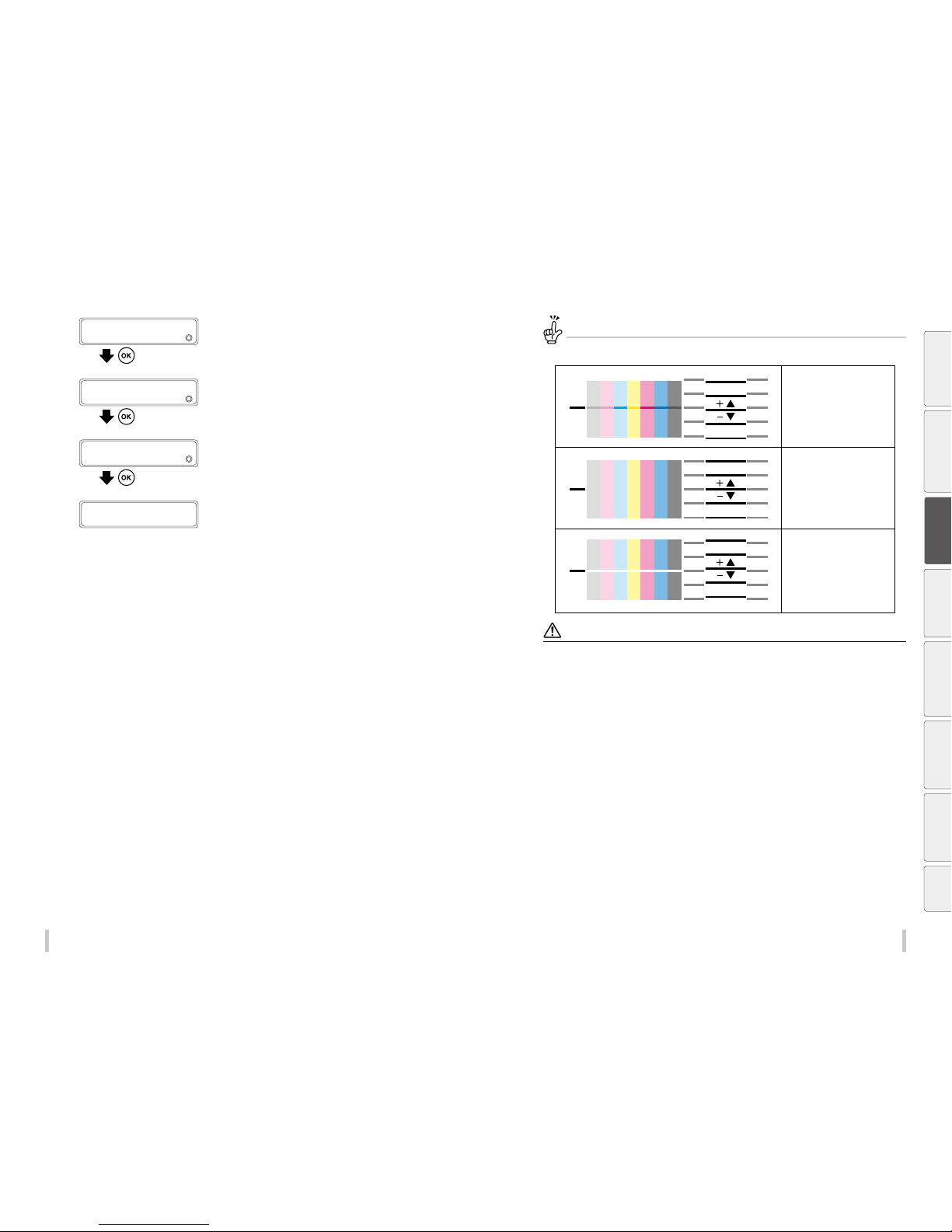
64 65
Adjustme nt Adjustme nt
14
>>>DR AFT
2
1 PATTERN
Press the OK key.
15
>1 PATTERN
2
*XXX.XXgYYY.YY%
Press the OK key.
16
>1 PATTERN
PRINT OK?
Press the OK to print the media advance
adjustment pattern.
17
>1 PATTERN
EXECUTING
The print starts.
18
Check the printed pattern visually.
When adjustment value is correct, the adjustment procedure is complete.
If the adjustment value is not suitable, perform the adjustment procedure again from step 9 through 17.
Check the media advance adjustment pattern
When the media advance
adjustment value is too low.
When the media advance
adjustment value is correct.
When the media advance
adjustment value is too high.
Notes
If the correct medi a advance adjustment value di ers between the media ri ght and left sides, set the aver age value.
If the correct medi a advance adjustment value di ers between the media ri ght and left sides, it may be caus ed by a skewed
media.
Check that the medi a has not skewed.
Before printing Loading the media
Adjustment
Maintenance
Advanced
operations
Troubleshooting Menu tree Appendix
Page 34
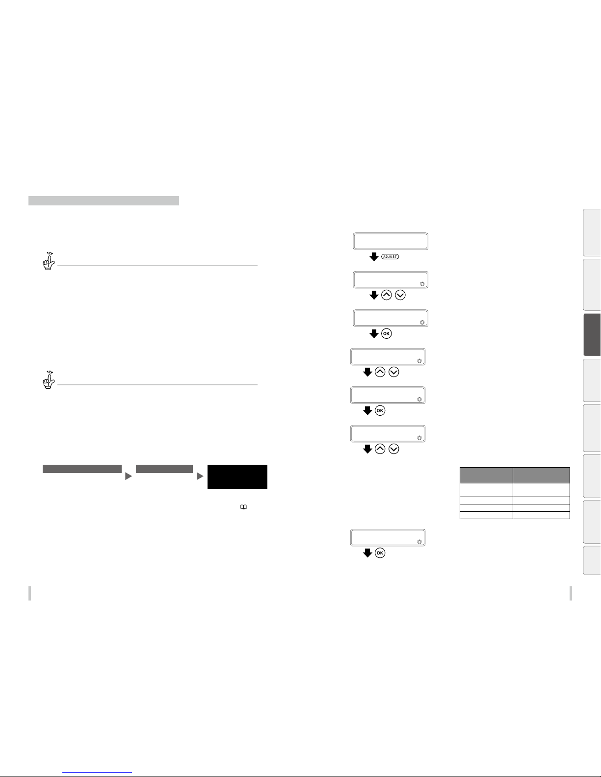
66 67
Adjustme nt Adjustme nt
Correcting ink output position: Bidirectional adjustment
During bidirectional printing, a slight dierence may appear in the ink output position between the rst scanning
direction and the second scanning direc tion.
To maintain a high print quality, perform bidirectional adjustment and set the most suitable bidirectional
adjustment value.
What is the timing to perform bidirectional adjustment?
When one of the following pa rameters has changed.
- The media has been change d
- The print mode has been cha nged
- The carriage speed (nor mal, slow) has been changed
- The height of the print heads has b een changed
When the bidirectio nal adjustment value is incorrect .
When the bidirectio nal adjustment value is incorrect , grains may appear on the printout or the prin tout may be
blurred.
Two modes are available for bidirectional adjustment: automatic print adjustment and manual print adjustment.
With automatic print adjustment, the printer prints an adjustment pattern, check the result with sensors, and set a
bidirectional adjustment value automatically.
With manual print adjustment, the printer prints an adjustment pattern, then the user selects visually a bidirectional
adjustment value and set the value on the printer.
How to dierentiate between automatic and manual print adjustment
Automatic print adjustment is reco mmended for the following users .
- Users who do not have much exper ience with the printer
- Users who nd manual print adjus tment dicult
- Users who want nish adjustment qu ickly
*Automatic print adjustment may not be availab le depending on the media ty pe. If automatic print adjustment
does not improve the print qualit y, use manual adjustment.
Manual print adjustment is recom mended for the following users .
- Users who needs the best p rint quality
Automatic print adjustment
<Worko w>
STEP1 STEP2
Completed
Select a bidirectional adjustment
pattern suitable for the print mode
Execute automatic print
adjustment
i
If the print quality has not
been improved
Perform manual print adjustment ( page 69)
<Procedure>
1
Load the media
Load the media in the same conditions as normal printing.
2
PRINTER READY
01: PAPER / 1626mm
Press the ADJUST key.
3
ADJUST
2
BIDIR POSITION
,
Press the Up and Down keys to select BIDIR
POSITION.
4
ADJUST
2
BIDIR POSITION
Press the OK key.
5
>BIDIR POSITION
2
MEDIA ADVANCE AUTO
,
Press the Up and Down keys to select MEDIA
ADVANCE AUTO.
6
>BIDIR POSITION
2
MEDIA ADVANCE AUTO
Press the OK key.
7
>>MEDIA ADVANCE AUTO
2
ALL
,
Press the Up and Down keys to a bidirectional
adjustment pattern suitable for the print
mode.
Bidirectional adjustment patterns corresponding to the
print modes
Bidirectional
adjustment pattern
Print mode
1: DRA,FAST PR,PRO Draft, fast pro duction, and
production
2: STD & QUALITY Standard and quality
3: HIGH QUALITY High quality
4: MAX QUALITY Max quality
8
>>MEDIA ADVANCE AUTO
2
ALL
Press the OK key.
Before printing Loading the media
Adjustment
Maintenance
Advanced
operations
Troubleshooting Menu tree Appendix
Page 35
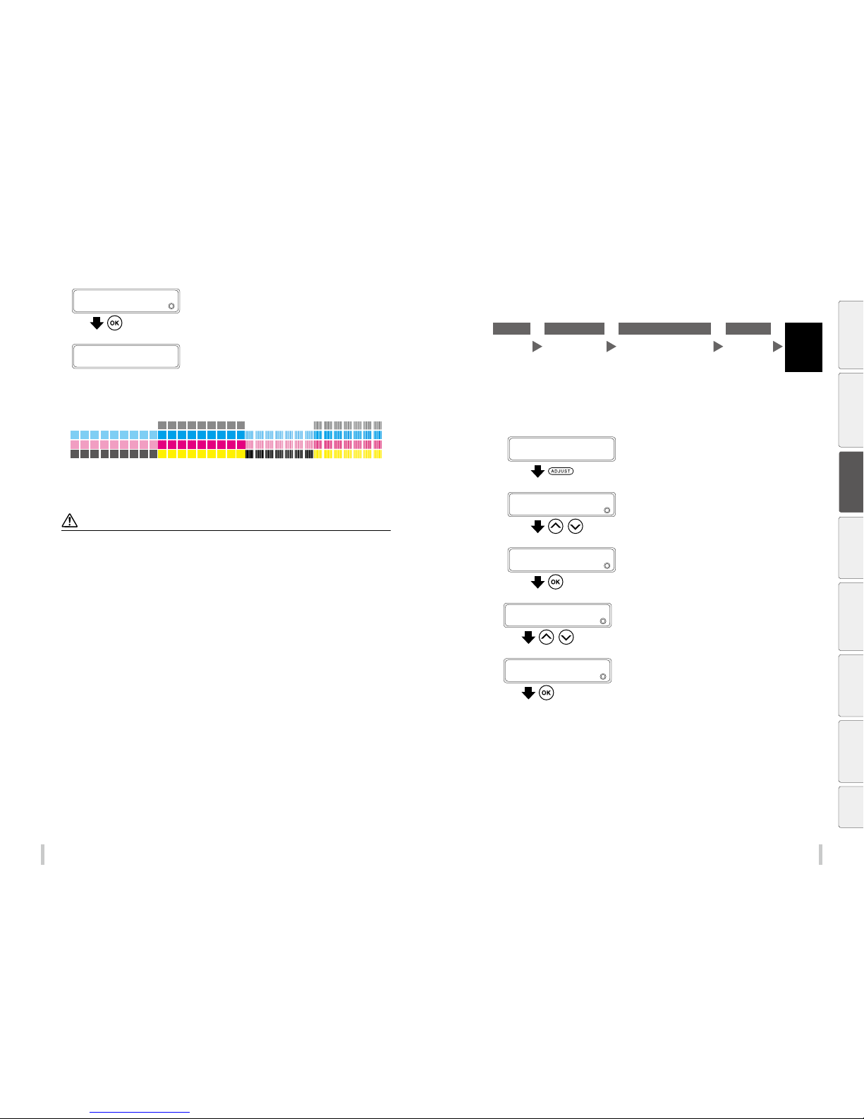
68 69
Adjustme nt Adjustme nt
9
>>MEDIA ADVANCE AUTO
PRINT OK?
Press the OK key to execute the bidirectional
adjustment.
>>MEDIA ADVANCE AUTO
EXECUTING
The printer prints the bidirectional adjustment pattern and
check the result with its sensors.
After the results have been checked, the printer
automatically set the bidirectional adjustment value. The
procedure is complete.
During this procedure, the printer prints and checks a pattern similar to the one shown below.
10
If the print quality has not been improved, perform manual print adjustment.
Note
The printer cannot set a co rrect adjustment value thr ough automatic print adjustme nt in the following cases. In suc h cases,
improve the conditions or pe rform manual print adjustm ent.
The automatic print ad justment determines mech anically the adjustment valu e, so absolute precision of the s etting cannot
be guaranteed.
- The media used makes the c heck via sensors impossib le.
<Examples>
- Transparent or colored media
- Media with a rough sur face
- Media with an extre mely high or low degree of re ection
- Media on which the pat tern cannot be printed prope rly, such as when the ink tends to bleed
- The media surface is so iled with dust, ink, ng er marks, etc.
- A gap tends to form betwe en the platen and the media
- Lots of nozzles are cl ogged
- The media heater tempe ratures are not suitable
- The environmental luminosity is too strong
Manual print adjustment
<Worko w>
STEP1 STE P2 STEP3 STEP4
Completed
Select the
print mode.
Print the
bidirectional
adjustment pattern.
Check visually the bidirectional
adjustment pattern and select
a bidirectional adjustment
value.
Enter the
bidirectional
adjustment
value.
<Procedure>
1
Load the media.
Load the media in the same conditions as normal printing.
2
PRINTER READY
01: PAPER / 1626mm
Press the ADJUST key.
3
ADJUST
2
MEDIA ADVANCE
,
Press the Up and Down keys to select BIDIR
POSITION.
4
ADJUST
2
BIDIR POSITION
Press the OK key.
5
>BIDIR POSITION
2
MEDIA ADVANCE AUTO
,
Press the Up and Down keys to select MEDIA
ADV MANUAL.
6
>BIDIR POSITION
2
MEDIA ADV MANUAL
Press the OK key.
Before printing Loading the media
Adjustment
Maintenance
Advanced
operations
Troubleshooting Menu tree Appendix
Page 36
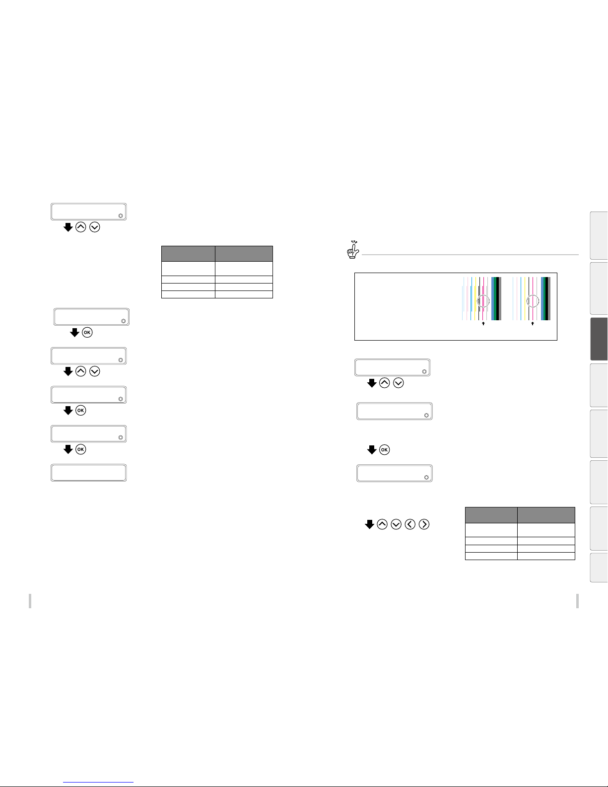
70 71
Adjustme nt Adjustme nt
7
>>MEDIA ADV MANUAL
2
1: DRA,FAST PR,P RO
,
Press the Up and Down keys to a bidirectional
adjustment pattern suitable for the print
mode.
Correspondence between the bidirectional adjustment
patterns and the print modes.
Bidirectional
adjustment pattern
Print mode
1: DRA,FAST PR,PRO Draft, fast pro duction, and
production
2: STD & QUALITY Standard and quality
3: HIGH QUALITY High quality
4: MAX QUALITY Max quality
8
>>MEDIA ADV MANUAL
2
1: DRA,FAST PR,P RO
Press the OK key.
9
>>>1: DRA,FAST PR ,PRO
2
EXECUTE
,
Press the Up and Down keys to EXECUTE.
10
>>>1: DRA,FAST PR ,PRO
2
EXECUTE
Press the OK key.
11
>>>1: DRA,FAST PR ,PRO
PRINT OK?
Press the OK key to print the bidirectional
adjustment pattern.
>>>1: DRA,FAST PR ,PRO
EXECUTING
The print starts.
12
Check visually the bidirectional adjustment pattern and select a adjustment value.
Select a value for both the right and left of each print head.
How to check a bidirectional adjustment pattern
Enter the value indicated in the case
where both lines are the closest for each
print head.
For example to set the left adjustment
value for the M print head, enter +2 as
in the pattern to the right the lines are
separated for -11 but th ey form only one
line for +2.
M
-11
M
+2
13
>>>1: DRA,FAST PR ,PRO
2
EXECUTE
,
Press the Up and Down keys to select right
or left adjustment and the color of the print
head.
This example explains how to set a bidirectional adjustment
value of +2 for the left adjustment of the M print head.
14
M : Print head color
L : Adjustment value right or lef t
±XX : Current adjustment value
>>>1: DRA,FAST PR ,PRO
2
M_L:±X X
Press the OK key.
15
*: Registration mark (A re gistration mark * is displayed if
the media preset is registered)
XXX. XX: Current adjustment value
YYY. YY: Adjus tment value after change (setting range -15
to +15 )
>>>>BIDIR ADJUST 1 M_L
2
*±XXg±YY
, , ,
Press the Right and Left keys to select the
digit, and press the Up and Down keys to
select a value for bidirectional adjustment.
Correspondence between the bidirectional adjustment
values and the print modes.
Bidirectional
adjustment value
Print mode
BIDIR ADJUST 1 Draf t, fast production, and
production
BIDIR ADJUST 2 Standard and quality
BIDIR ADJUST 3 High quality
BIDIR ADJUST 4 Max qualit y
Before printing Loading the media
Adjustment
Maintenance
Advanced
operations
Troubleshooting Menu tree Appendix
Page 37
7372
Adjustme nt
16
>>>>BIDIR ADJUST 1 M_L
2
*±XXg+02
,
Press the OK key to set the bidirectional
adjustment value, or press the CANCEL key to
exit BIDIR ADJUST 1 M_L.
17
>>>BID IR MA NUAL1
2
M_L:±X X
,
Set the bidirectional adjustment values of
the other side and the other print heads
following the same procedure.
When bidirectional adjustment values have
been set for both sides of all print heads, the
adjustment procedure is complete.
Before printing Loading the media Adjustment
Maintenance
Advanced
operations
Troubleshooting Menu tree Appendix
Maintenance
Page 38
74 75
Maintenance Maintenance
Daily maintenance
Perform daily maintenance to maintain the printer in good condition and maximize the print quality.
Pay particularly attention to the following three items.
- Clean the capping unit (start maintenance) every day.
- Check the level of the wiper cleaning liquid every day. Supply liquid if the level is low.
- Print heads are highly-precise parts. Do not wipe the nozzle surfaces directly.
Daily maintenance can be executed from the operation panel.
The daily maintenance items are listed below.
No. Item Daily
When a message is
displayed
When it is noticeably
dirty
Consumables
A Media installation
B Start maintenance
Capping unit cleaning
IP6-252 Cap cleaning liquid set A *1
IP5-120 Cleaning stick *1
IP7-163 Cleaning roller set *1
Normal cleaning
C Nozzle print
D Waste ink bottle check and replacement
IP6-109 Waste ink bottle
E Wiper cleaning liquid che ck and supply
IP6-251 Wiper cleaning liquid set A *1
F Wiper blade cleanliness check and replacement
IP6-259 Wiper blade *1
G Wiper sponge replacement
IP6-258 Wiper sponge
H Printer cleaning
Edge guard cleaning
IP6-147 Cleaning swab *1
IP6-252 Cap cleaning liquid set A *1
Head guard cleaning
Platen cleaning
Paper guide cleaning
Pressure roller cleaning
Front cover cleaning
I Sheet mount cleaning
IP6-261 Sheet mount cleaning kit A
*1 Also included in the IP6-250 daily maintenance kit A.
•••
Check
•••
Set
•••
Replace
•••
Clean
•••
Panel operation
•••
Remove
Before printing Loading the media Adjustment
Maintenance
Advanced
operations
Troubleshooting Menu tree Appendix
Page 39
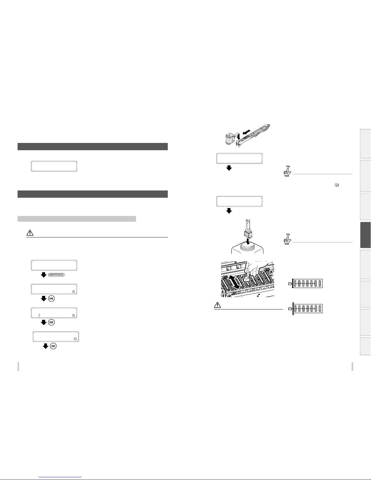
76 77
Maintenance Maintenance
Routine maintenance
A Media installation
1
CHECK MEDIA
FOR WRINKLES
Check that the media is not wrinkled.
If it is wrinkled, either set the media again or feed it up to an
area without wrinkles.
* Printing on wrinkled media may damage the nozzle
surfaces .
B Start maintenance (capping unit cleaning, normal cleaning)
Select START MAINTENANCE on the panel and follow the instructions to perform both capping unit cleaning and
normal cleaning at the same time. You may also perform normal cleaning only in this manner.
Performing capping unit cleaning and normal cleaning at the same time
CAUTI ON
To prevent the ink from drying ins ide the print head’s nozzles:
- Do not leave the printer wi th the carriage detached f rom the capping unit.
- Complete the cappi ng unit cleaning operation an d cap the print heads within 5 minute s.
1
PRINTER READY
01: PAPER / 1626mm
Press the MAINTENANCE key.
2
MAINTENANCE
2
START MAINTENANCE
Press the OK key.
3
>START MAINTENANCE
2
OK?
Press the OK key.
4
>START CAP MAINT?
OK/CANCEL
Press the OK key to start the operation.
To cancel the operation, press the CANCEL key.
5
(1)
(2)
Attach the cleaning roller to the cleaning
stick.
6
1ST WIPING OPERATION
PLEASE WAIT 1:00
Carriage stops moving.
After the wiping of the print heads finishes, the carriage
moves to the maintenance area.
The printer issues a warning beep.
When the carriage moves, th e printer issues a
warning beep.
To disable the warning beep, see the
page
149
.
7
OPEN COVERS
AND CLEAN CAPS
After the carriage has moved to the
maintenance area, open the front cover, and
then the capping cover.
8
Soak the cleaning roller in the cap cleaning
liquid.
TIP
To keep the cap cleaning liquid clean, do not s oak
the cleaning roller in the cap cl eaning liquid bottle
again after you have cleaned th e caps with it.
9
CAUTI ON
Be careful so that the cap c leaning liquid does not
adhere to any part other th an the caps.
The cleaning roller is i ntended for a single use only. Use
a new cleaning roller for each cleaning.
If the caps are not completely clean after one cleaning
operation, use a new roll er and clean the caps again.
With the 6 color specic ation printer, the rightmost cap
does not need do be cleaned.
Clean the top surface of the caps by rolling
the cleaning roller.
(1) Roll the roller back and forth on each cap.
(2) Then roll the roller back and forth 10 times on each
cap.
Before printing Loading the media Adjustment
Maintenance
Advanced
operations
Troubleshooting Menu tree Appendix
Page 40
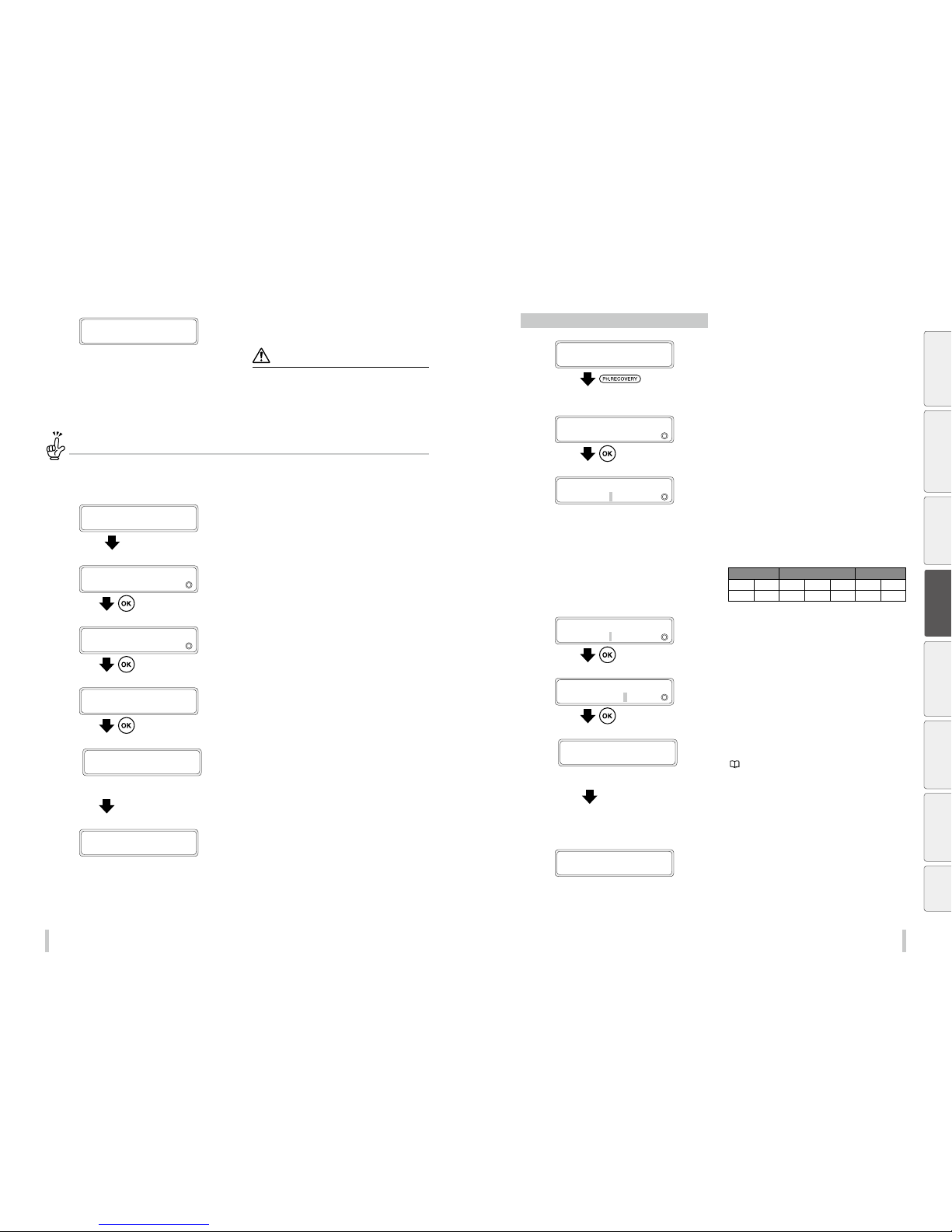
78 79
Maintenance Maintenance
10
AFTER CLEAN ING CAPS
CLOSE COVERS
Close the capping cover and the front cover.
The carriage returns automatically to the home position.
CAUTI ON
Do not let unnecessari ly the capping unit separated
from the print heads. O therwise the print heads m ay dry
and cause the printer to mal function.
Be careful so that the cap c leaning liquid does not
adhere to any part other th an the caps.
Missing dots are still found even after the cap cleaning...
If you still see missing dots even a fter the cap cleaning above, check th e caps visually and remove foreign matte rs and ink stains
from them with a cleaning swa b dampened with cap cleaning liquid .
11
2ND WIPING OPER ATION
PLEASE WAIT 1:00
After the wiping of the print heads finishes, the carriage
moves to the home position.
12
CAP MAINT COM PLETED?
YES:OK/N O:CANCEL
Press the OK key.
13
START PH RECOVERY?
OK/CANCEL
Press the OK key.
14
PH RECOVERING XXXXXXX
BOTTLE IS EMPT Y?
Press the OK key.
15
Y:YY : Required time
PH RECOVERING XXXXXXX
REQUIRED TIME Y:YY
The cleaning is complete.
Press the OK key.
PERFORM NOZZLE PRINT
Performing normal cleaning independently
1
PRINTER READY
01: PAPER / 1626mm
Press the PH.RECOVE RY key.
You can perform PH recovery in the following situations.
- When the printer is idle online
- When the printer is offline
- During printing
- When the printer is in pause
2
PH. RECOVERY
2
NORMAL
Press the OK key.
3
>NORMAL
2
PRINT HEAD:1234567
Press the Right and Left keys to select the
digit, and press the Up and Down keys to
select the print head number.
The numbers correspond to the print head to be cleaned.
The correspondence between the ink colors and the print head
numbers is shown in the table below.
Head group 1 Head group 2 Head group 3
Lc Lm C Y K M Gy
1 2 3 4 5 6 7
4
>NORMAL
2
PRINT HEAD: 34567
Press the OK key.
5
>NORMAL XXXXXXX
BOTTLE IS EMPT Y?
Press the OK key.
The numbers correspond to the print head to be cleaned.
6
Y:YY: R equir ed tim e
PH RECOVERING XXXXXXX
REQUIRED TIME Y:YY
The cleaning is complete.
An error occurs if the waste ink bottle is full. Follow the
instructions to replace the waste ink bottle.
(
page 82 Waste ink bottle ch eck and
replacement)
Start the print head cleaning.
Print head cleaning takes several minutes.
When the cleaning starts, the required time is displayed and
the time is counted down every 10 seconds.
PRINTER READY
01: PAPER / 1626mm
Online idle: Switches to online state
Offline: Stays o ffline
Printing: Resume printing
In pause: Stays in pause
Before printing Loading the media Adjustment
Maintenance
Advanced
operations
Troubleshooting Menu tree Appendix
Page 41
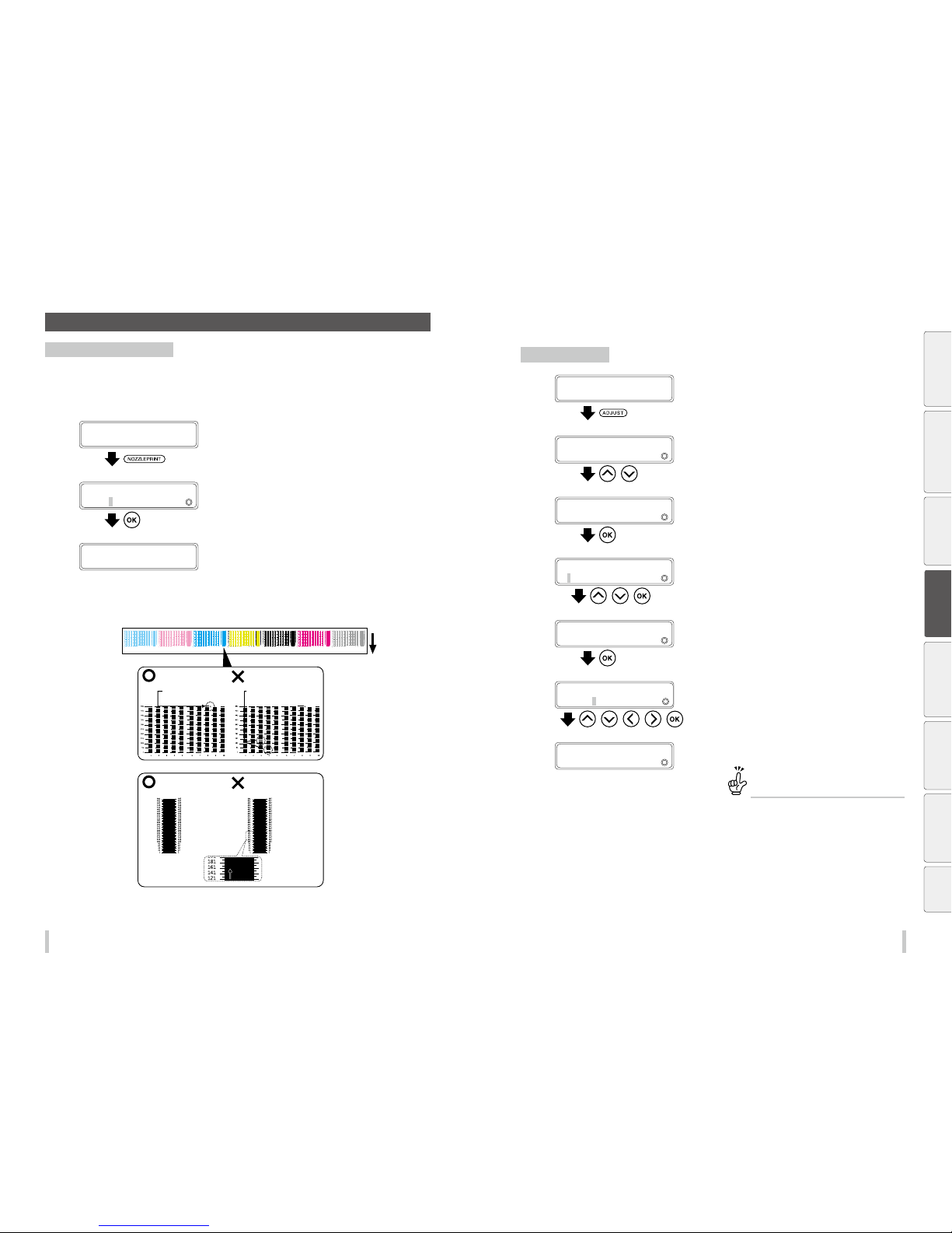
80 81
Maintenance Maintenance
C Nozzle print
Print the nozzle print pattern
Use NOZZLE PRINT to check if any print head nozzles (ink ejection outlet) are clogged.
Perform a NOZZLE PRINT every day to check the print heads before printing or after the capping unit has been
detached to perform a cap cleaning or other operation.
1
PRINTER READY
01: PAPER / 1626mm
Press the NOZZLEPRI NT key.
2
NOZZLE PRINT
2
PRINT?
Press the OK key to start the operation.
To cancel the operation, press the CANCEL key.
3
NOZZLE PRINT
2
EXECUTING
The nozzle print pattern prints.
4
Check for missing dots and incorrect print.
The following pattern is printed.
Missing lines are found
No line is missing and the
printout is correct
OK
NG
Bent lines are found
No line is bent and the
printout is correct
OK
NG
If the spaces between
the lines are even, no
line is bent.
If there are uneven
spaces between lines,
some lines may be bent.
Example: Bent lines are found
Mark for the last nozzle (nozzle 508)
Check that nozzle print is complete up
to the right of this mark.
Example when lines for nozzles 24 and
133 are missing in the printout.
Check that there are no missing or bent lines.
If missing or bent lines are found with the nozzle print, perform the normal cleaning.
If missing or bent lines remain after several normal cleanings, set [NOZZLE MAP] with the procedure below.
Nozzle map setting
1
PRINTER READY
01: PAPER / 1626mm
Press the ADJUST key.
You can set up to 10 nozzle map parameters for each print
head.
2
ADJUST
2
MEDIA ADVANCE
,
Press the Up and Down keys to select
NOZZLE M AP.
3
ADJUST
2
NOZZLE PRINT
Press the OK key.
4
>NOZZLE PRINT
2
Lc
, ,
Press the Up and Down keys to select the
color to be set and press the OK key.
This example explains how to set a nozzle number 365 for
the nozzle map 01 of Lc head.
5
>>NOZZLE PRINT Lc
2
#01:***
Press the OK key.
6
>>Lc:# 01
2
***g365
, , , ,
Press the Up, Down, Left, Right keys to set
the nozzle map or nozzle number, and then
press the OK key.
7
>>Lc:# 01
2
***g365
The setting is complete.
To check the numbers of the nozzles
with nozzle map
The numbers of the nozz les for which nozzle map
has been set are indicated o n the nozzle print
pattern printout.
Before printing Loading the media Adjustment
Maintenance
Advanced
operations
Troubleshooting Menu tree Appendix
Page 42
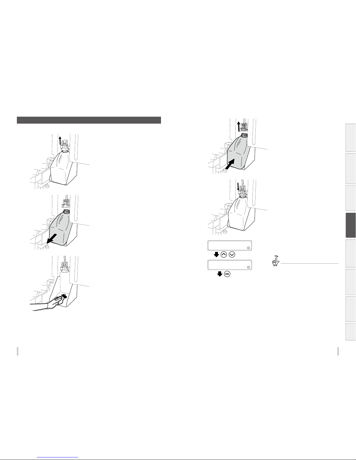
82 83
Maintenance Maintenance
D Waste ink bottle check and replacement
1
Slide the lever up and lift the splash guard
suciently to remove the waste ink bottle.
The ink drips from the tube. Leave it for a while.
2
Carefully pull out the full waste ink bottle,
taking care not to spill any on the printer or
on the oor.
Securely close the cap on the waste ink bottle.
3
Wipe o the spilt ink in the waste ink bottle
unit.
4
Slide the lever up and install a empty waste
ink bottle.
5
Lower the lever, and make sure that the
splash guard was lowered.
Then the operation panel will request you to
reset the waste ink counter.
6
RESET WST INK COUNT ?
2
NO
,
RESET WST INK COUNT ?
2
YES
Press the Up and Down keys to select YES,
and then press the OK key.
If you do not reset the waste ink counter...
The printer will not issue the mess age prompting
you to replace the waste ink bot tle when the bottle
will full. Then the waste ink w ill overow.
Before printing Loading the media Adjustment
Maintenance
Advanced
operations
Troubleshooting Menu tree Appendix
Page 43
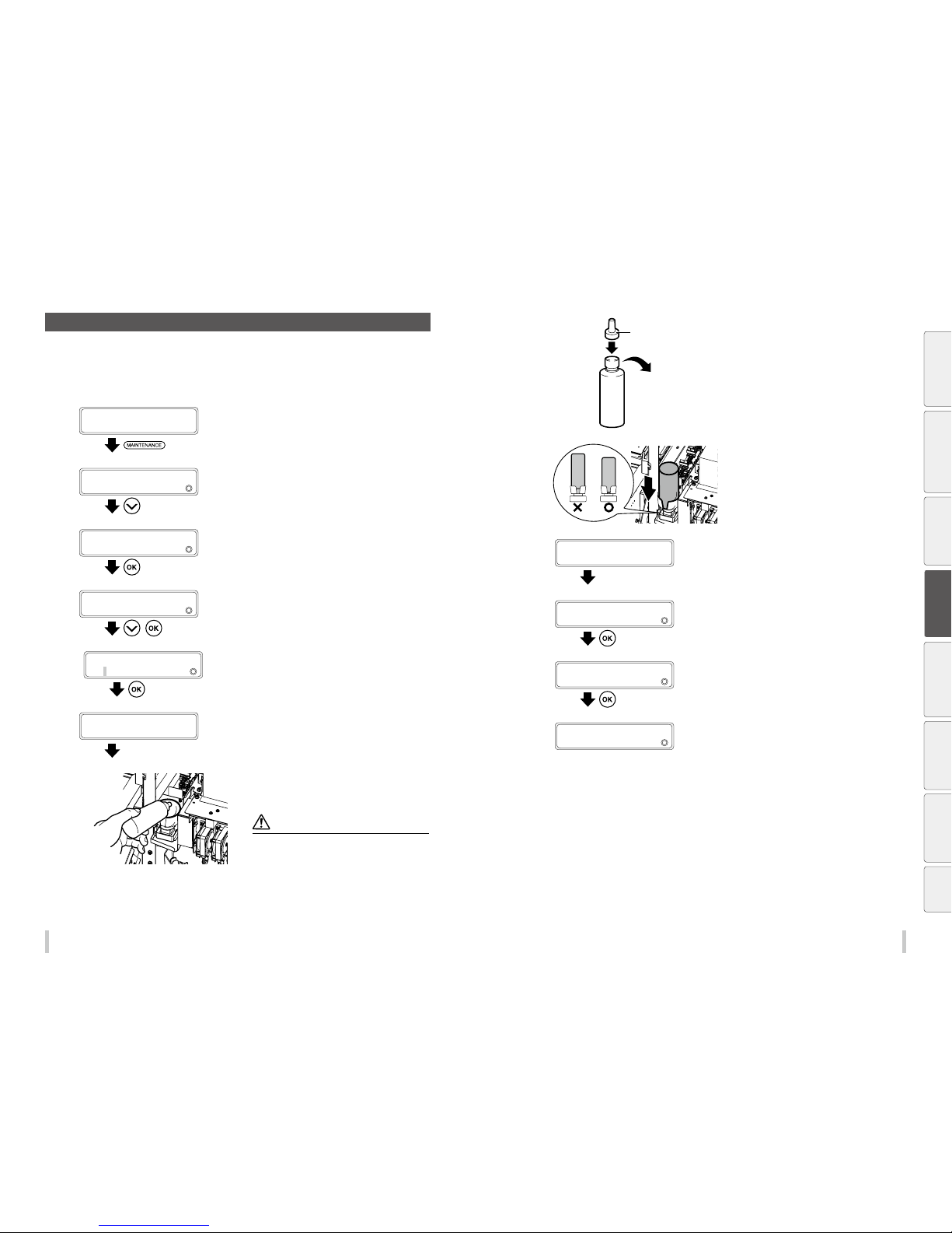
84 85
Maintenance Maintenance
E Wiper cleaning liquid check and supply
Supply wiper cleaning liquid with the procedure below in the following cases.
- When a printer message prompts you to do so.
- When you notice that the liquid level is low during a daily inspection. Generally, wiper cleaning liquid should be
supplied approximately once per month.
1
PRINTER READY
01: PAPER / 1626mm
Press the MAINTENANCE key.
2
MAINTENANCE
2
START MAINTENANCE
Press the Down key to select WIPER
MAINTENANCE.
3
MAINTENANCE
2
WIPER MAINTENANCE
Press the OK key.
4
WIPER MAINTENANCE
2
REPLACE LIQUID
,
Press the Down key to select REPL ACE
LIQUID, and then press the OK key.
5
>REPLACE LIQUID
2
OK?
Press the OK key to start the operation.
To cancel the operation, press the CANCEL key.
6
OPEN COVERS, REPLACE
WIPER CLEANG LIQUID
Open the front cover, and then the capping
cove r.
7
Raise the old wiper cleaning liquid bottle a
little and pull out the bottle after making sure
that all the liquid has owed into the printer.
Note
Visually check that the w aste ink bottle is not full bef ore
removing it.
8
Printer set cap
Replace the cap of the new wiper cleaning
liquid bottle with the printer dedicated cap.
9
Set the wiper cleaning liquid bottle in the
printer and push in the stopper of the printer
cap by pressing the top of it.
10
AFTER REPLACI NG WCL
CLOSE COVERS
Close the cap cover and the front cover.
11
REPLACED WCL?
2
NO
Press the Down key to select YES.
12
REPLACED WCL?
2
YES
Press the OK key.
13
>WIPER MAINTENANCE
2
REPLACE LIQUID
Before printing Loading the media Adjustment
Maintenance
Advanced
operations
Troubleshooting Menu tree Appendix
Page 44
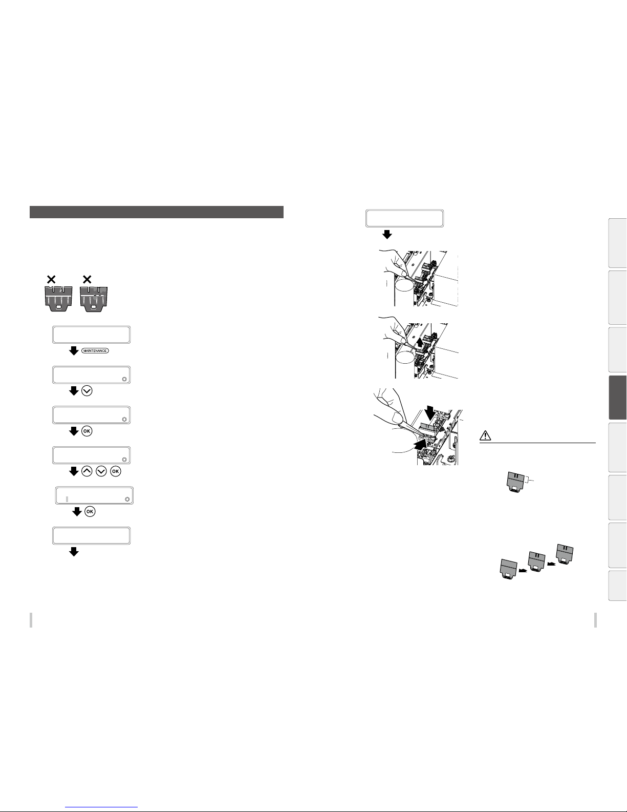
86 87
Maintenance Maintenance
F Wiper blade cleanliness check and replacement
Replace the wiper blade in the following cases.
- When a printer message prompts you to do so.
- When you notice that the blade is not clean or damaged during a daily inspection.
Follow the procedure below to replace the wiper blade.
Always replace the 3 blades at the same time.
1
PRINTER READY
01: PAPER / 1626mm
Press the MAINTENANCE key.
2
MAINTENANCE
2
START MAINTENANCE
Press the Down key to select WIPER
MAINTENANCE.
3
MAINTENANCE
2
WIPER MAINTENANCE
Press the OK key.
4
WIPER MAINTENANCE
2
REPLACE BLADE
, ,
Press the Up and Down keys to select
REPLACE BLADE, and then press the OK ke y.
5
>REPLACE BLADE
OK?
Press the OK key to start the operation.
To cancel the operation, press the CANCEL key.
6
WIPER IS MOVING...
PLEASE WAIT
The wiper stops moving.
7
OPEN COVERS AND
REPLACE WIPER BL ADE
Open the front cover, and then the capping
cove r.
8
Pinch the lower edge of the wiper blade with
a pair of tweezers and pull out the plastic
protrusion.
9
Lift upward to remove the wiper blade.
10
(1)
(2)
Pinch the rubber portion of a new wiper
blade with the pair of tweezers and insert the
wiper blade straight from the top. Install it so
that the plastic protrusion ts into the hole of
the rubber portion.
CAUTI ON
The front and back of the wi per blade are the same.
As the upper porti on of the wiper blade touches di rectly
the print head, do not touc h it with your hands or pinch
it with the tweezers w hen handling.
Upper portion of
the wiper blade
Replace the two rubbe r blades and the sponge blade .
Install the blad es in the following order star ting from
the rear.
Rubber g Rubber g Sponge
If you make a mistake in the orde r, cleaning will not
be performed e ectively and the print heads w ill
malfunction.
(3) Sponge
(2) Rubber
(1) Rubber
Before printing Loading the media Adjustment
Maintenance
Advanced
operations
Troubleshooting Menu tree Appendix
Page 45
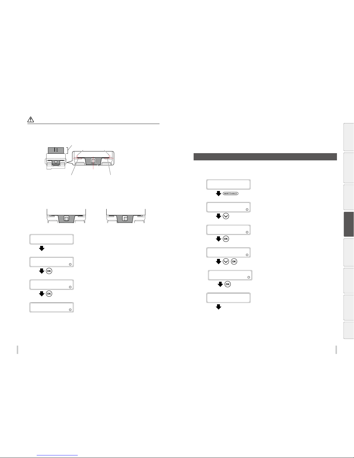
88 89
Maintenance Maintenance
Notes
If the rubber blades a re not installed correct ly, the print head cleaning will not be e ective. As a result not onl y the print
quality will decrea se, but this may also lead to a malfunc tion.
Refer to the examp le below to install the blades co rrectly.
Protrusion
The protrusion is in the center
Parts are in contact at both the right and left sides
The spaces on the right and left are equal
They are parallel
<Correct installation>
The cleaning will not be e ective if the blades are mis takenly installed as shown b elow.
Refer to the examp le above to correct the position .
The blade is installed at a slant The blade is not aligned in the vertical
and horizontal directions
<Incorrect installation>
11
AFTER REPLACI NG WB
CLOSE COVERS
Close the cap cover and the front cover.
12
REPLACED WIPER BL ADE?
2
NO
Press the Down key to select YES.
13
REPLACED WIPER BL ADE?
2
YES
Press the OK key.
14
>WIPER MAINTENANCE
2
REPLACE BLADE
G Wiper sponge replacement
Replace the wiper sponge with the procedure below when a printer message prompts you to do so. Generally, the
wiper sponge should be replaced approximately once every six month.
1
PRINTER READY
01: PAPER / 1626mm
Press the MAINTENANCE key.
2
MAINTENANCE
2
START MAINTENANCE
Press the DOWN key to select WIPER
MAINTENANCE.
3
MAINTENANCE
2
WIPER MAINTENANCE
Press the OK key.
4
WIPER MAINTENANCE
2
REPLACE SPONGE
,
Press the Down key to select REPL ACE
SPONGE, and then press the OK key.
5
>REPLACE SPONGE
OK?
Press the OK key to start the operation.
To cancel the operation, press the CANCEL key.
6
OPEN COVERS AND
REPLACE WIPER SPO NGE
Open the front cover, and then the capping
cove r.
Maintenance when a message
is displayed
Before printing Loading the media Adjustment
Maintenance
Advanced
operations
Troubleshooting Menu tree Appendix
Page 46
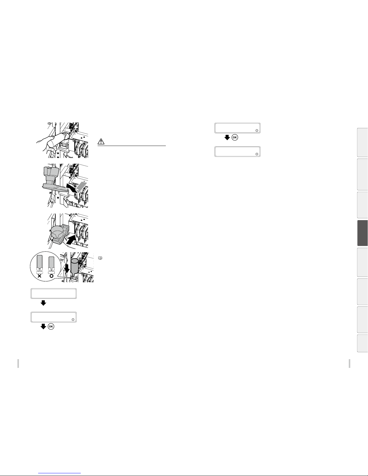
90 91
Maintenance Maintenance
7
Raise the wiper cleaning liquid bottle a little
and pull out the bottle after making sure that
all the liquid has owed into the printer.
Note
Visually check that the w aste ink bottle is not full bef ore
removing it.
8
Lift the wiper sponge little by little while
pulling it toward you. After conrming that
the liquid in the wiper sponge has completely
owed in the printer, remove the wiper
sponge.
9
Install a new wiper sponge.
Insert it as far as it goes until it clicks.
10
Install a new wiper cleaning liquid bottle.
( page 84 Wiper cleaning liquid check and
supply)
11
AFTER REPLACING WIPER
SPONGE, CLOSE COVERS
Close the cap cover and the front over.
12
REPLACED SPONGE?
2
NO
Press the Down key to select YES.
13
REPLACED SPONGE?
2
YES
Press the OK key.
14
>WIPER MAINTENANCE
2
REPLACE SPONGE
You may also be prompted by a printer message to replace one of the following consumables.
- Waste ink bottle
- Wiper cleaning liquid bottle
- Wiper blade
See Routine maintenance for the replacement procedures for these consumables.
Before printing Loading the media Adjustment
Maintenance
Advanced
operations
Troubleshooting Menu tree Appendix
Page 47
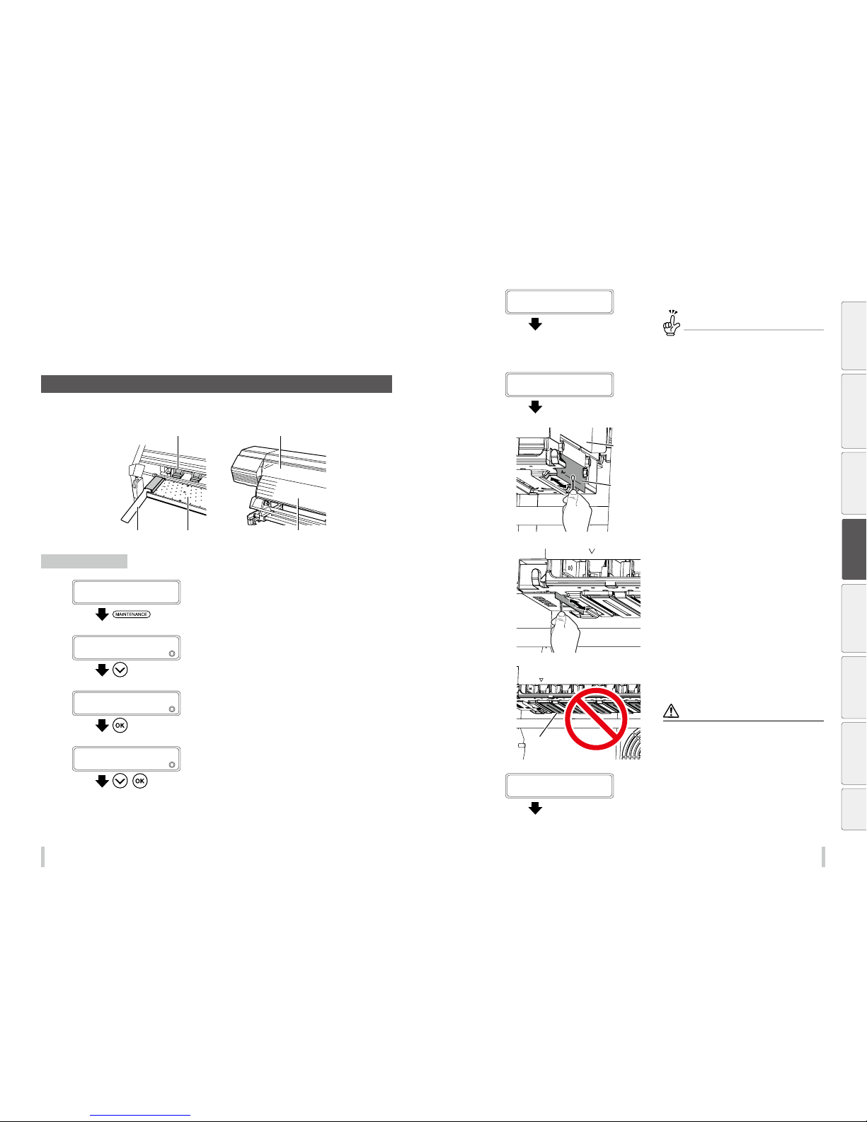
92 93
Maintenance Maintenance
H Printer cleaning
Clean the printer when the dirt becomes noticeable.
Media edge guards Platen Paper guide
Pressure roller Front cover
Head guard cleaning
1
PRINTER READY
01: PAPER / 1626mm
Press the MAINTENANCE key.
2
MAINTENANCE
2
START MAINTENANCE
Press the Down key to select PH
MAINTENANCE.
3
MAINTENANCE
2
PH MAINTENANCE
Press the OK key.
4
PH MAINTENANCE
2
SET PH FOR CHECK
,
Press the Down key to select SET PH FOR
CHECK, and then press the OK key.
5
CARRIAGE IS MOVIN G
PLEASE WAIT
Carriage stops moving.
The carriage moves to the maintenance area.
The printer issues a warning beep.
When the carriage moves, th e printer issues a
warning beep.
To disable the warning beep, see the
pag e 149
.
6
OPEN COVERS AND
CHECK PRINT HEADS
Open the front cover, and then the
maintenance cover.
7
Carriage
Head guard
Clean the head guard at the right and left
sides of the carriage using a cleaning swab or
a soft cloth.
Nozzle surfaces
Do not clean directly the nozzle surfaces.
(Execute the dedicated sheet mount cleaning
to clean them.)
CAUTI ON
Do not rub the head nozz le surfaces with a cleaning
swab. It may cause the printer t o malfunction.
8
CHECK PRINT HEADS
THEN CLOSE COVERS
Close the maintenance cover and the front
cove r.
Maintenance when the printer
is dirty
Before printing Loading the media Adjustment
Maintenance
Advanced
operations
Troubleshooting Menu tree Appendix
Page 48
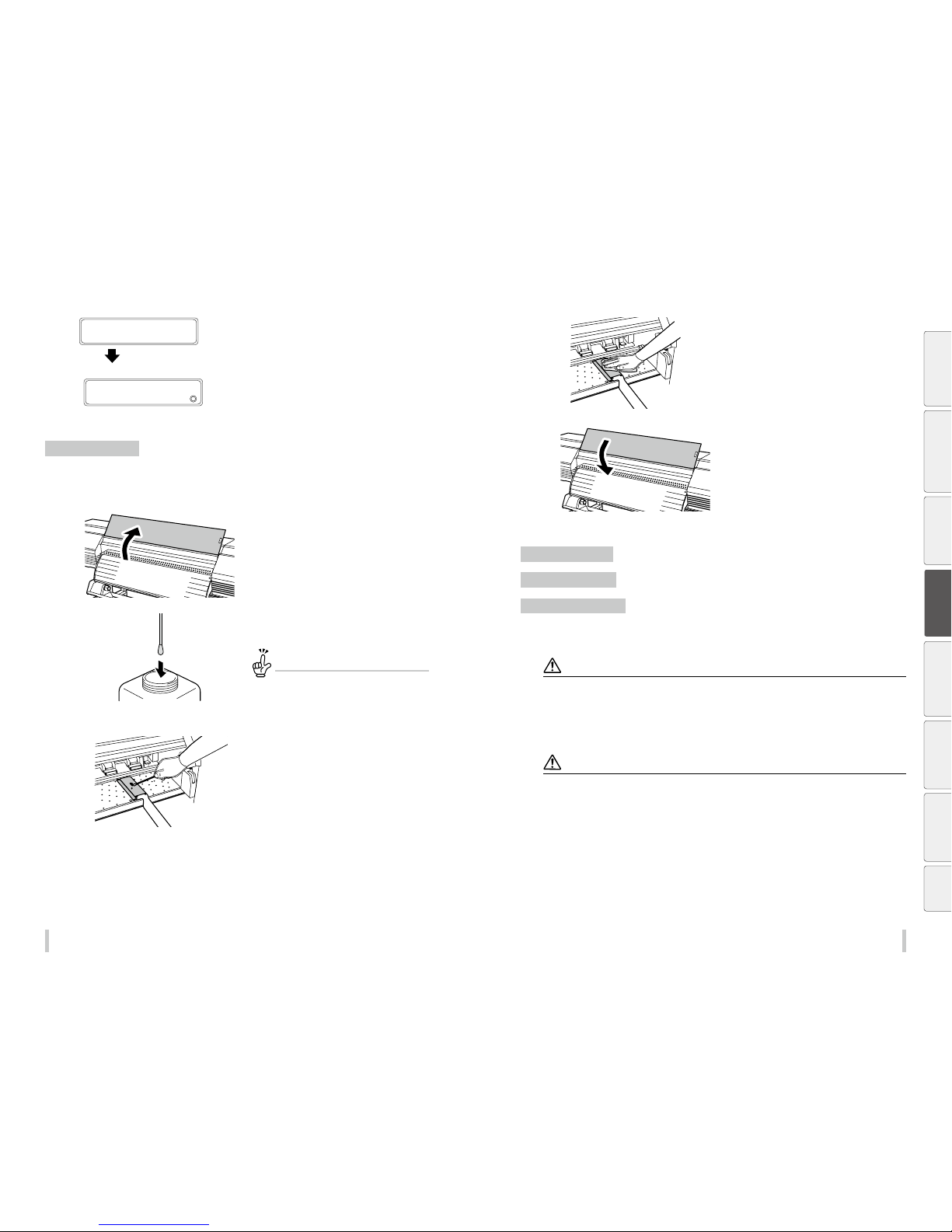
94 95
Maintenance Maintenance
9
CARRIAGE IS MOVIN G
PLEASE WAIT
Carriage stops moving.
PH MAINTENANCE
2
SET PH FOR CHECK
Edge guard cleaning
1
If a media is installed, remove it.
2
Open the front cover.
3
Soak a cleaning swab in the cap cleaning
liquid.
TIP
To keep the cap cleaning liquid clean, do not so ak the
cleaning swab in the cap cleaning liquid bottle again
after you have cleaned the ed ge guards with it.
The cleaning swab is intende d for a single use only.
Use a new cleaning swab for each cle aning.
4
Check visually for stains on the media edge
guards.
5
Clean the stains with a soft and clean cloth.
6
Close the front cover.
Front cover cleaning
Paper guide cleaning
Pressure roller cleaning
If the printer exterior is smeared, moisten a soft cloth with water or water-diluted neutral detergent, wring it, and
clean the exterior.
Notes
Always turn the printer o bef ore cleaning or doing other ma intenance operation on the print er.
Never use volatile solvent su ch as thinner and benzene. The co ating may come o or discolor.
In case of dust or paper dust, clean the printer with a vacuum cleaner. If lots of ink or other substance adhere to the
printer, clean it with soft cloth moistened with a neutral detergent.
Notes
Always turn the printer o bef ore cleaning or doing other ma intenance operation on the print er.
Do not blow paper dust away. The pri nter may malfunction if pape r dust or dust enters inside. Th is may also degrade the
print quality.
If the end of the media use d is glued to the paper tube, the g lue may adhere to the paper guide or t he platen. In such cases,
be sure to remove all adhered glue.
Before printing Loading the media Adjustment
Maintenance
Advanced
operations
Troubleshooting Menu tree Appendix
Page 49
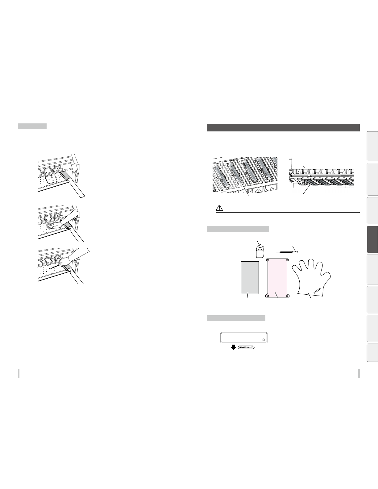
96 97
Maintenance Maintenance
Platen cleaning
Use the following procedure to clean the platen if
- vinyl chloride adhesive gets on the platen
- ink drops on the platen (the procedure to clean ink stains is explained)
1
Open the front cover and soak up the ink on
the platen with a piece of waste media.
2
Wipe the ink stains o the platen with a soft
cloth moistened with a neutral detergent.
3
If the ink penetrates into the vacuum hole on
the platen, wipe out the ink stuck in the hole
with a commercially available cotton swab*.
Then, moisten the cotton swab with neutral
detergent and wipe out once more.
*: Use a cotton swab with a tip of 3 mm diameter.
I Sheet mount cleaning
If the capping unit or the nozzle surfaces on the print heads are very dirty, clean these parts with a head cleaning
sheet.
Nozzle surface
Cap
<Capping unit><Print head>
Note
Do not rub the print heads wi th a cleaning swab. This may cause th e printer to malfunction.
Preparing the sheet mount cleaning
Sheet mount cleaning liquid
Dropper
Cap cleaning sheet
(gray sheet)
Head cleaning sheet
(pink sheet)
Glove
Performing sheet mount cleaning
Perform the operation following the instructions below.
1
PRINTER READY
01: PAPER / 1626mm
Press the MAINTENANCE key.
Before printing Loading the media Adjustment
Maintenance
Advanced
operations
Troubleshooting Menu tree Appendix
Page 50
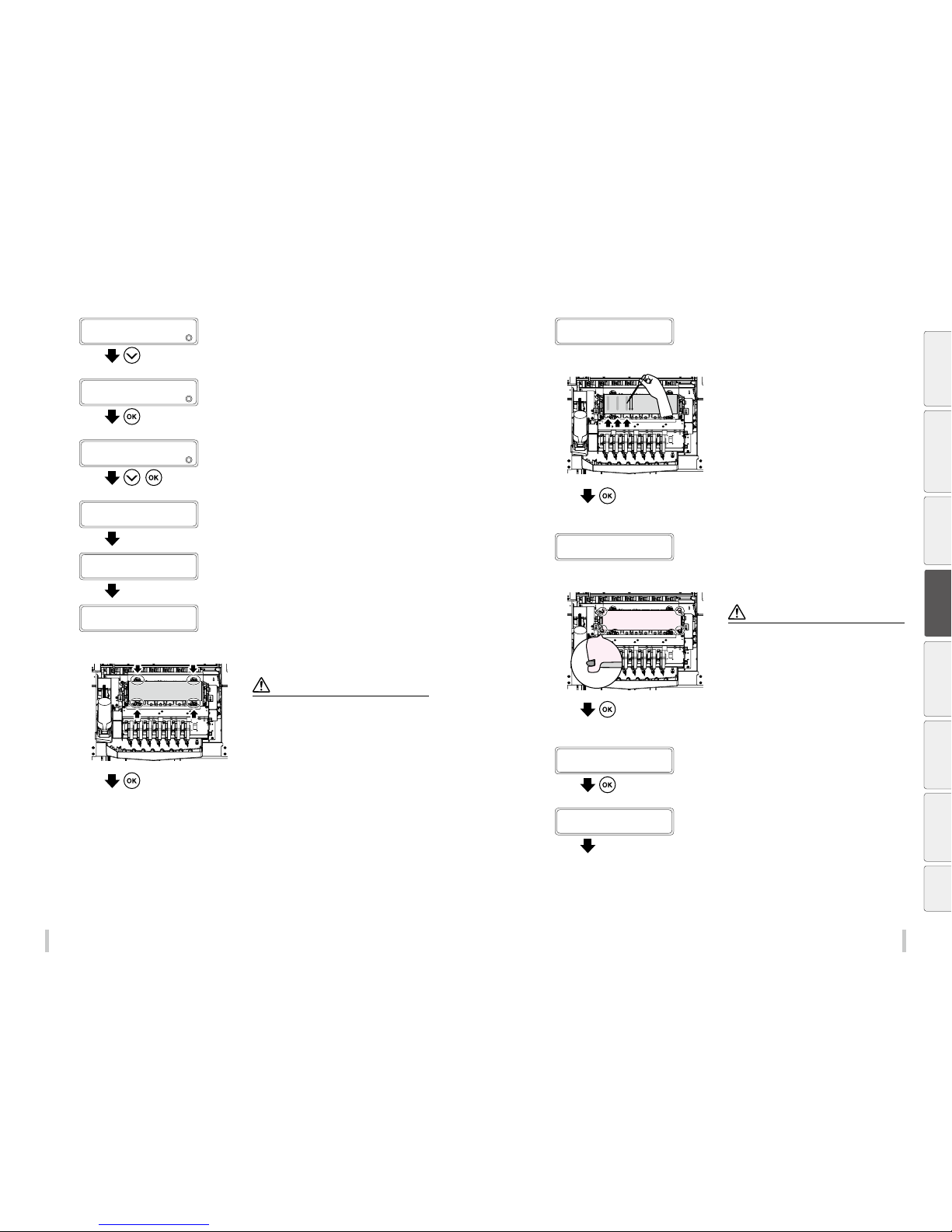
98 99
Maintenance Maintenance
2
MAINTENANCE
2
START MAINTENANCE
Press the Down key to select PH
MAINTENANCE.
3
MAINTENANCE
2
PH MAINTENANCE
Press the OK key.
4
PH MAINTENANCE
2
SHEET MOUNT CLNG
,
Press the Down key to select SHEET MOUNT
CLNG, and then press the OK key.
CARRIAGE IS MOVIN G
PLEASE WAIT
Carriage stops moving.
The carriage moves to the maintenance position.
5
OPEN COVERS
Open the front cover, and then the
maintenance cover.
6
INSTALL GRAY SHEET
Place the gray sheet (cap cleaning sheet) to
cover all seven caps.
Note
Do not place the sheet onto t he 4 rollers indicated by
the arrows in the gure on the l eft. Otherwise th is may
decrease the cleaning eectiveness.
Press the OK key.
7
DRIP CLEANING LIQUID
ON GRAY SHEET
Apply 1 cc of cleaning liquid twice to the
sheet for each cap.
Draw 1 cc of sheet mount cleaning liquid with the dropper
(use the gradations), and apply 2 cc to the gray sheet (cap
cleaning sheet) for each color.
Apply the liquid in the vertical direction starting f rom each
color tube indicated by the arrows twice in parallel.
For the 6 color specifications printer, apply the liquid on the
sheet only for the six first caps starting from the lef t.
(For the 7 color specifications printer, apply the liquid for
the seven caps.)
Press the OK key.
8
INSTALL PINK SHEET
Place the pink sheet (head cleaning sheet)
over the gray sheet and attach the hooks.
Note
Securely attach th e four hooks. Other wise the sheet may
detach when entering i nto contact with the print heads ,
which decreases the eectiveness of the cleaning.
The four hook s are placed at the four corners of t he
capping unit as shown in the gure to the left.
Press the OK key.
9
CLOSE COVERS
Close the capping cover and the front cover.
CARRIAGE IS MOVIN G
PLEASE WAIT
Carriage stops moving.
The carriage moves to the home position.
Before printing Loading the media Adjustment
Maintenance
Advanced
operations
Troubleshooting Menu tree Appendix
Page 51
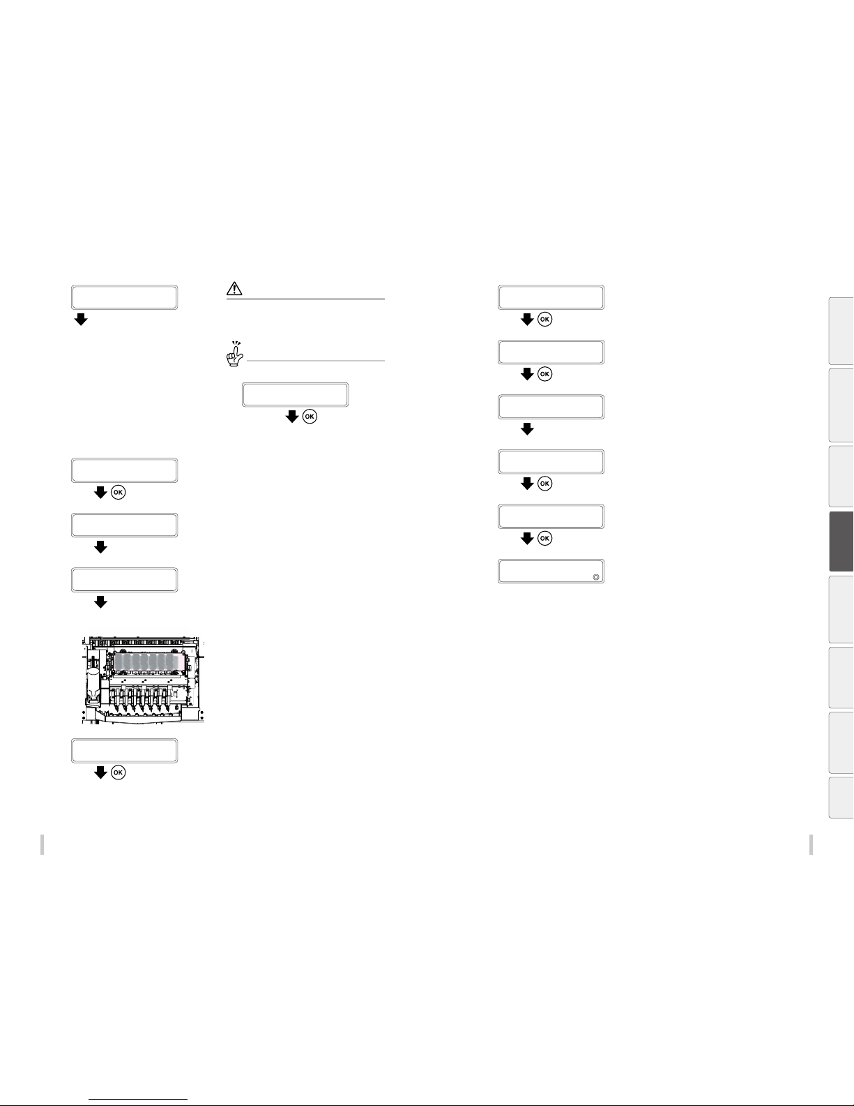
100 101
Maintenance Maintenance
10
CLEANING…
TIME REQUIRED X.X X
The sheet mount cleaning is complete.
Note
The recommended time for the cleaning is 8 hours.
The eectiveness of the cleaning decreases if shorter
cleaning is performed.
To interrupt the sheet mount cleaning
Press the CANCEL key.
CANCEL SHEET MOU NT
CLEANING?
Go to 12.
11
CLEANING COMPLETE
PRESS OK BUTTON
Press the OK key.
CARRIAGE IS MOVIN G
PLEASE WAIT
Carriage stops moving.
The carriage moves to the maintenance position.
12
OPEN COVERS
Open the front cover, and then the capping
cove r.
13
REMOVE PINK SHEET
Remove the pink sheet (head cleaning sheet)
and press the OK key.
14
REMOVE GRAY SHEET
Remove the gray sheet (cap cleaning sheet)
and press the OK key.
15
CLOSE COVERS
Close the capping cover and the front cover.
CARRIAGE IS MOVIN G
PLEASE WAIT
Carriage stops moving.
The carriage moves to the home position.
START CLEANING
BOTTLE IS EMPT Y?
Check that the waste in bottle is not full.
PH RECOVERING XXXXXXX
REQUIRED TIME Y:YY
(The cleaning start s.)
PH MAINTENANCE
2
SHEET MOUNT CLNG
Sheet mount cleaning is complete.
Before printing Loading the media Adjustment
Maintenance
Advanced
operations
Troubleshooting Menu tree Appendix
Page 52
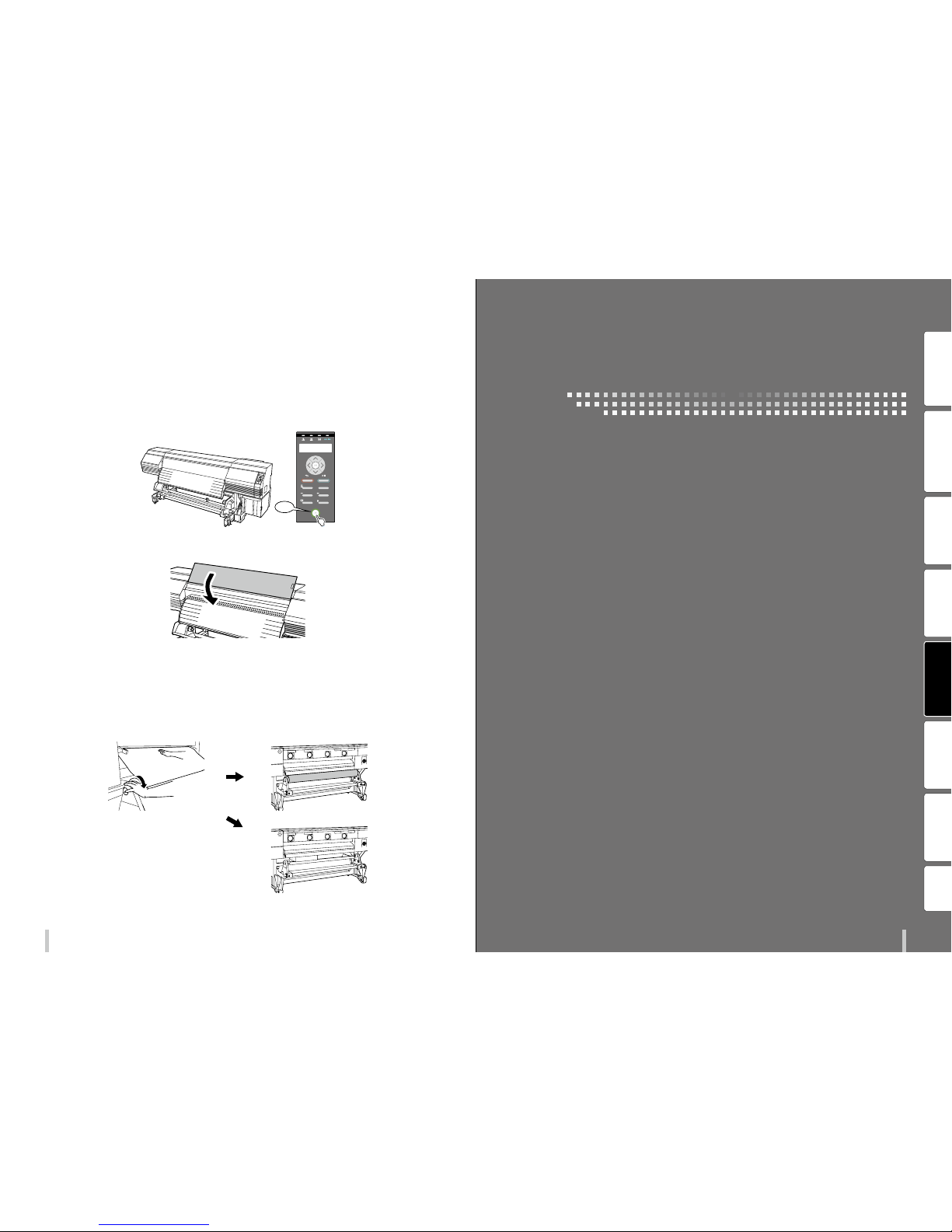
103102
Maintenance
After the operation of the day
The printer has an internal clock which allows it to wash the print heads automatically, ushing some ink through
the print heads, which keeps the print heads in good condition. To ensure the printer’s automatic maintenance
operation, after the operations of the day keep the printer in the conditions below.
1. Keep the printer turned on.
POWER
HEATER MENU
CANCEL
SET
ORIGIN
ONLINE
ADJUST
MAINTENANCE
NOZZLE PRINT PH.RECOVERY
ON
2. Keep the front cover closed.
3. Take up the media on the TUR unit, or remove the media from the printer.
If you keep t he medi a loade d on the pri nter for a lo ng time, t he media m ay wrink le on the p laten or a
grippi ng trace may b e lef t on the me dia. To keep the m edia in g ood cond ition, t he oper ation be low is
recommended.
Especially after printing on vinyl media, be sure to remove it from the printer. Note that vinyl media wrinkles
easi ly.
Before printing Loading the media Adjustment Maintenance
Advanced
operations
Troubleshooting Menu tree Appendix
Advanced operations
Page 53
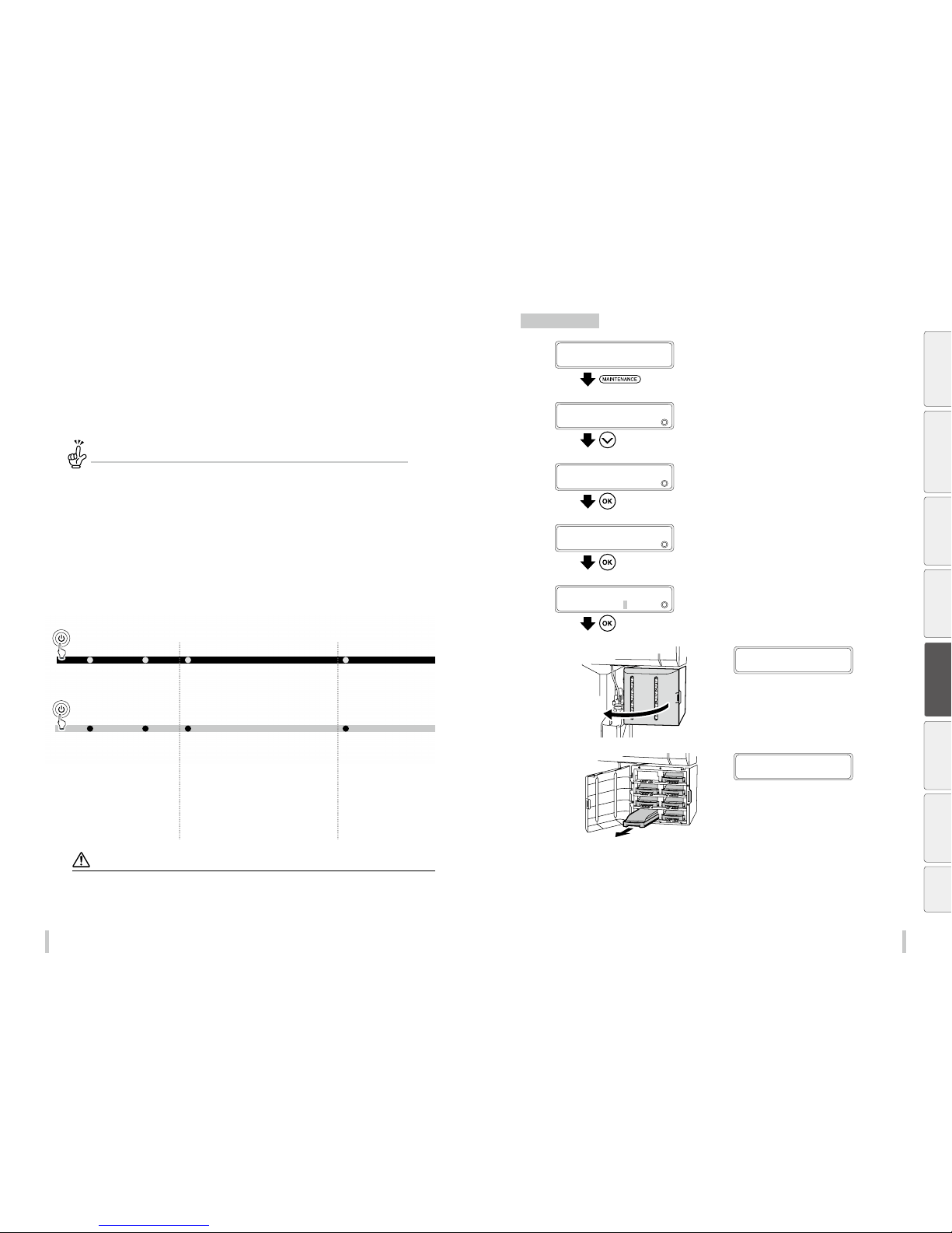
104 105
Advanced operation s Advanced operation s
When not using the printer for
more than 2 weeks
Always set the printer power to on to perform the ll cap operation.
What is ll cap?
To clear clogged nozzles, use th e ll cap function. This func tion lls the caps with ink to soak the pr int head (nozzle
surface) in the ink for a minimum of 1 to 2 ho urs. If possible, leave the printer overni ght.
Use this function also when s everal cleaning operations could not cl ear the clogged nozzles.
The printer has an internal clock which allows it to automatically wash the print heads, ushing some ink through
the print heads, which keeps the print heads in good condition. The printer automatically washes the print heads 72
hours after the last printing, and then washes them every three days.
If the printer is turned o for a long period, this process above does not happen. If the ink does not ow through the
print heads regularly, the ink will dry inside the nozzle, reaching a point where they cannot be recovered and the
print heads will malfunction. This will lead to a replacement of the print heads.
If you have to leave the printer turned o for a long time, follow the instructions below.
For a short period
Clean the print head and the ink flow path with the
storage liquid, and leave the printer with storage
liquid filled.
Prepare the storage liquid set (IP7-137).
Clean the print head and the ink flow path with the
cleaning liquid.
Prepare the cleaning liquid set (IP7-136).
After the head wash, Insert ink trays and charge the
ink system.
Perform the daily maintenance.
When leaving the Printer for
more than one month,
contact your service
representative beforehand.
The service call error is
displayed regardless of
whether service cleaning has
been performed or
not. Contact your service
representative.
For a several days
For two weeks or more
Service cleaning
Head wash
Power-off
Power-on
Charging ink after head wash
Daily maintenance
For one month or more
CAUTI ON
To protect the print heads, do n ot leave the printer for more than one mo nth with no ink in the system.
During the service cleaning or head wash, do not open or close the front cover or the pressure roller lever. Otherwise, the
printer may restart it s initial operation from the be ginning, and waste the ink and cl eaning liquid.
Service cleaning
1
PRINTER READY
01: PAPER / 1626mm
Press the MAINTENANCE key.
2
MAINTENANCE
2
START MAINTENANCE
Press the Down key to select PH
MAINTENANCE.
3
MAINTENANCE
2
PH MAINTENANCE
Press the OK key.
4
>PH MAINTENANCE
2
CLEAN FOR STOR AGE
Press the OK key.
5
>>CLEAN FOR STOR AGE
BOTTLE IS EMPT Y?
Conrm that the waste ink bottle is empty
and press the OK key.
6
OPEN INK BOX COVER
Open the ink box cover.
7
REMOVE K INK
CARTRIDGE
Remove the ink trays.
Before printing Loading the media Adjustment Maintenance
Advanced
operations
Troubleshooting Menu tree Appendix
Page 54
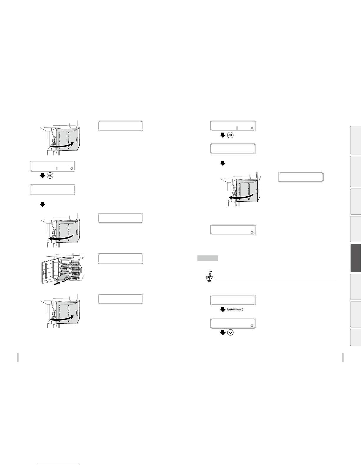
106 107
Advanced operation s Advanced operation s
8
CLOSE INK BOX COVER
Close the ink box cover.
9
START DRAINING
BOTTLE IS EMPT Y?
Conrm that the waste ink bottle is empty
and press the OK key.
Draining starts.
Y: YY : Required time (min:sec, decrease ever y 10 seconds)
DRAINING
PLEASE WAIT Y:YY
10
OPEN INK BOX COVER
Open the ink box cover.
11
LOAD
K SL cartridge
Insert the ink trays with storage liquid
cartridges into the slots of the ink box.
12
CLOSE INK BOX COVER
Close the ink box cover.
13
START SL CHARGING
BOTTLE IS EMPT Y?
Conrm that the waste ink bottle is empty
and press the OK key.
Y :YY : Required time (min:sec, dec rease every 10 seconds)
CHARGING SL
PLEASE WAIT Y:YY
14
OPEN INK BOX COVER
Open the ink box cover.
15
Repeat steps 7 to 14.
>PH MAINTENANCE
2
CLEAN FOR STOR AGE
Head wash
Set the cleaning liquid car tridges to the optional ink trays in adv ance to facilitate the procedure.
1
PRINTER READY
01: PAPER / 1626mm
Press the MAINTENANCE key.
2
MAINTENANCE
2
START MAINTENANCE
Press the Down key to select PH
MAINTENANCE.
Before printing Loading the media Adjustment Maintenance
Advanced
operations
Troubleshooting Menu tree Appendix
Page 55
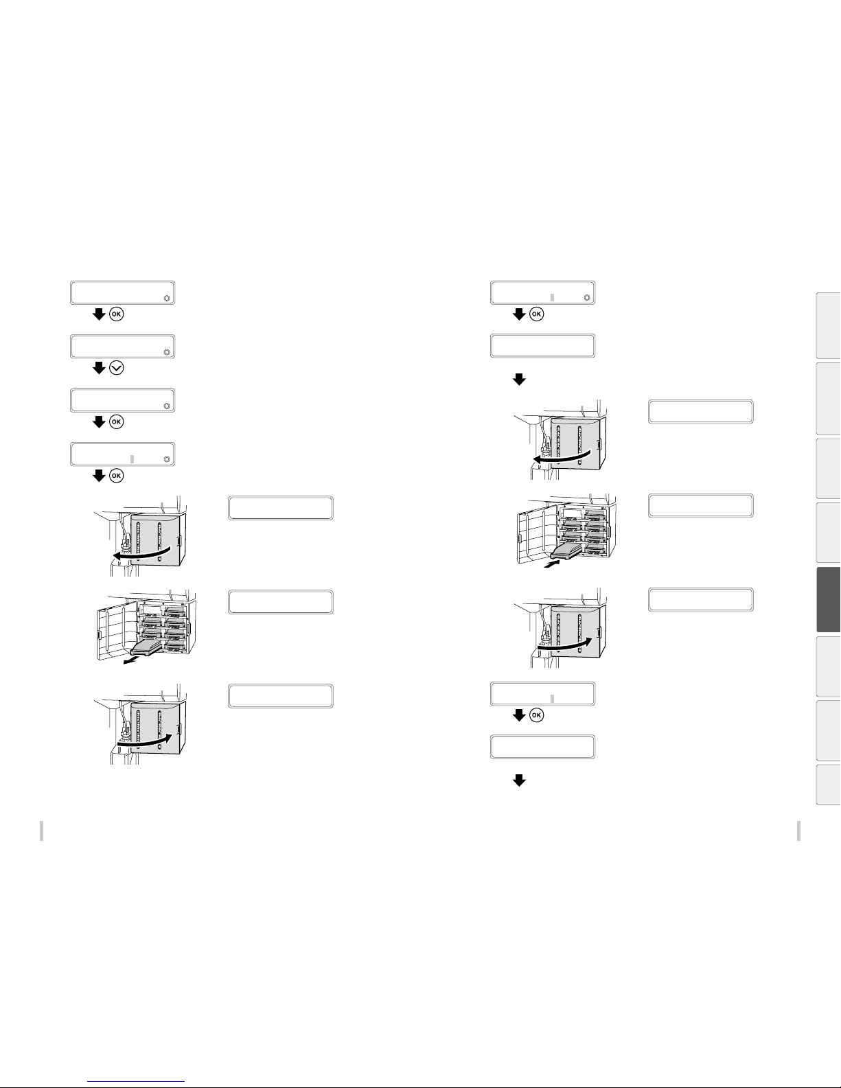
108 109
Advanced operation s Advanced operation s
3
PH MAINTENANCE
2
CLEAN FOR STOR AGE
Press the OK key.
4
PH MAINTENANCE
2
CLEAN FOR STOR AGE
Press the Down key to select CLEAN PH & INK
SYS.
5
>PH MAINTENANCE
2
CLEAN PH & INK SYS
Press the OK key.
6
>>CLEAN PH & INK SYS
BOTTLE IS EMPT Y?
Conrm that the waste ink bottle is empty
and press the OK key.
7
OPEN INK BOX COVER
Open the ink box cover.
8
REMOVE
K SL cartridge
Remove the ink trays.
9
CLOSE INK BOX COVER
Close the ink box cover.
10
START DRAINING
BOTTLE IS EMPT Y?
Conrm that the waste ink bottle is empty
and press the OK key.
Draining starts.
Y: YY : Required time (min:sec, decrease ever y 10 seconds)
DRAINING
PLEASE WAIT Y:YY
11
OPEN INK BOX COVER
Open the ink box cover.
12
LOAD
K CL cartridge
Install the ink trays containing the cleaning
liquid cartridges.
13
CLOSE INK BOX COVER
Close the ink box cover.
14
START CL CHARGING
BOTTLE IS EMPT Y?
Conrm that the waste ink bottle is empty
and press the OK key.
Y: YY : Required time (min:sec, decrease ever y 10 seconds)
CHARGING CL
PLEASE WAIT Y:YY
Before printing Loading the media Adjustment Maintenance
Advanced
operations
Troubleshooting Menu tree Appendix
Page 56
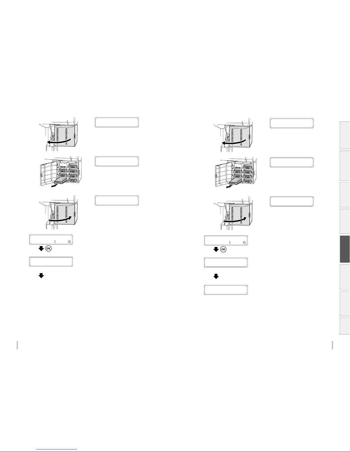
110 111
Advanced operation s Advanced operation s
15
OPEN INK BOX COVER
Open the ink box cover.
16
REMOVE
K CL cartridge
Remove the ink trays containing the cleaning
liquid cartridges.
17
CLOSE INK BOX COVER
Close the ink box cover.
18
START DRAINING
BOTTLE IS EMPT Y?
Conrm that the waste ink bottle is empty
and press the OK key.
Draining starts.
Y: YY : Required time (min:sec, decrease ever y 10 seconds)
DRAINING
PLEASE WAIT Y:YY
19
Repeat steps 11 to 15.
20
OPEN INK BOX COVER
Open the ink box cover.
21
REMOVE
K CL cartridge
Remove the ink trays containing the cleaning
liquid cartridges.
22
CLOSE INK BOX COVER
Close the ink box cover.
23
START DRAINING
BOTTLE IS EMPT Y?
Conrm that the waste ink bottle is empty
and press the OK key.
Draining starts.
Y:YY : Required time (min:sec, decrease every 10 seconds)
DRAINING
PLEASE WAIT Y:YY
OPEN INK COVER
K LOAD INK PACK
Before printing Loading the media Adjustment Maintenance
Advanced
operations
Troubleshooting Menu tree Appendix
Page 57
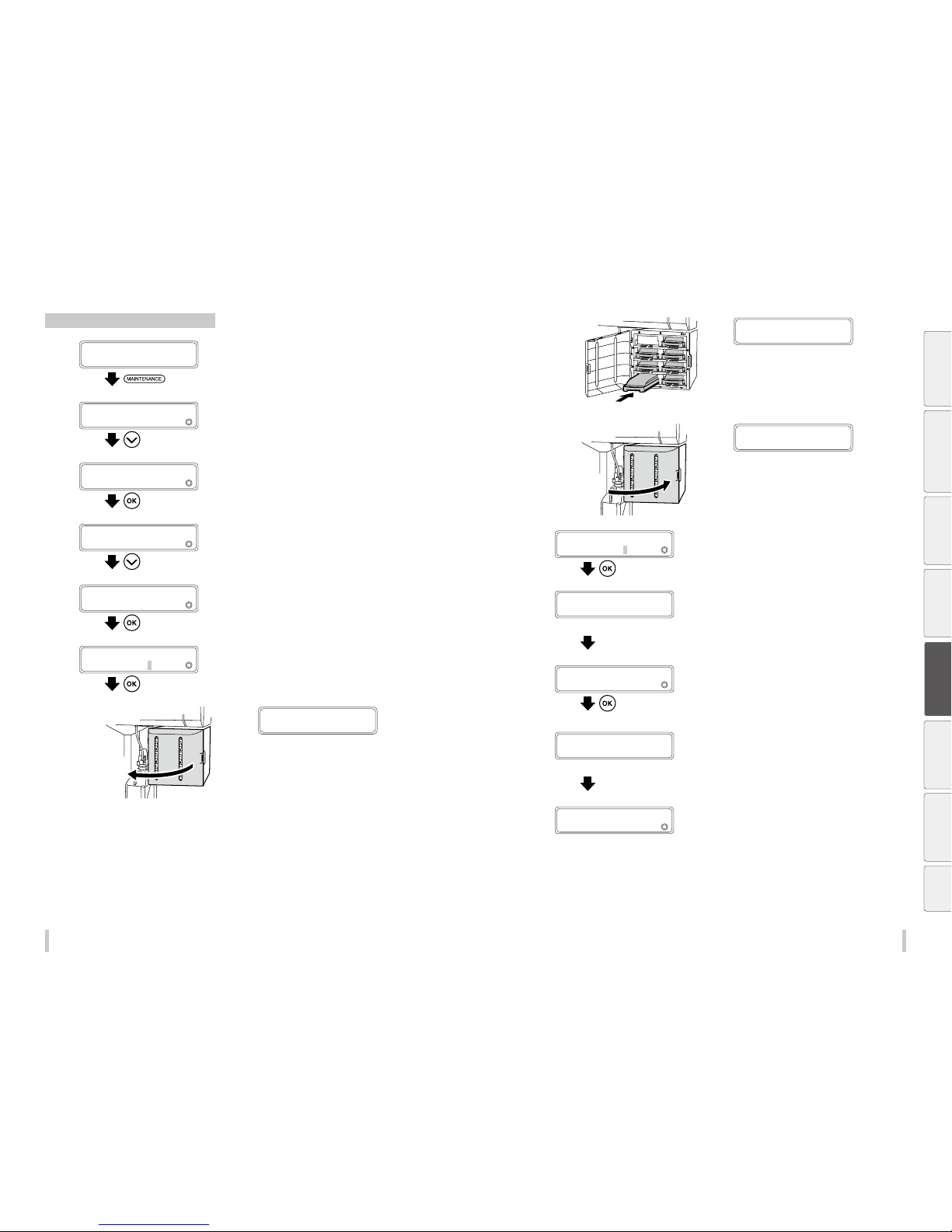
112 113
Advanced operation s Advanced operation s
Priming the ink system after head wash
1
PRINTER READY
01: PAPER / 1626mm
Press the MAINTENANCE key.
2
MAINTENANCE
2
START MAINTENANCE
Press the Down key to select PH
MAINTENANCE.
3
PH MAINTENANCE
2
CLEAN FOR STOR AGE
Press the OK key.
4
PH MAINTENANCE
2
CLEAN FOR STOR AGE
Press the Down key to select PRIME INK
SYSTEM .
5
>PH MAINTENANCE
2
PRIME INK SYSTEM
Press the OK key.
6
>>PRIME INK SYSTEM
BOTTLE IS EMPT Y?
Conrm that the waste ink bottle is empty
and press the OK key.
7
OPEN INK BOX COVER
Open the ink box cover.
8
INSTALL K
INK CARTRIDGE
Insert the ink trays.
9
CLOSE INK BOX COVER
Close the ink box cover.
10
START INK CHARGING
BOTTLE IS EMPT Y?
Conrm that the waste ink bottle is empty
and press the OK key.
Y:YY : Required time (min:sec, decrease every 10 seconds)
CHARGING INK
PLEASE WAIT Y:YY
11
START CLEANING
BOTTLE IS EMPT Y?
Press the OK key.
Normal cleaning starts.
The panel display returns to the previous screen after the
cleaning has finished.
Y: YY : Required time (min:sec, dec rease every 10 seconds)
PH RECOVERING XXXXXXX
REQUIRED TIME Y:YY
>PH MAINTENANCE
2
PRIME INK SYSTEM
Before printing Loading the media Adjustment Maintenance
Advanced
operations
Troubleshooting Menu tree Appendix
Page 58
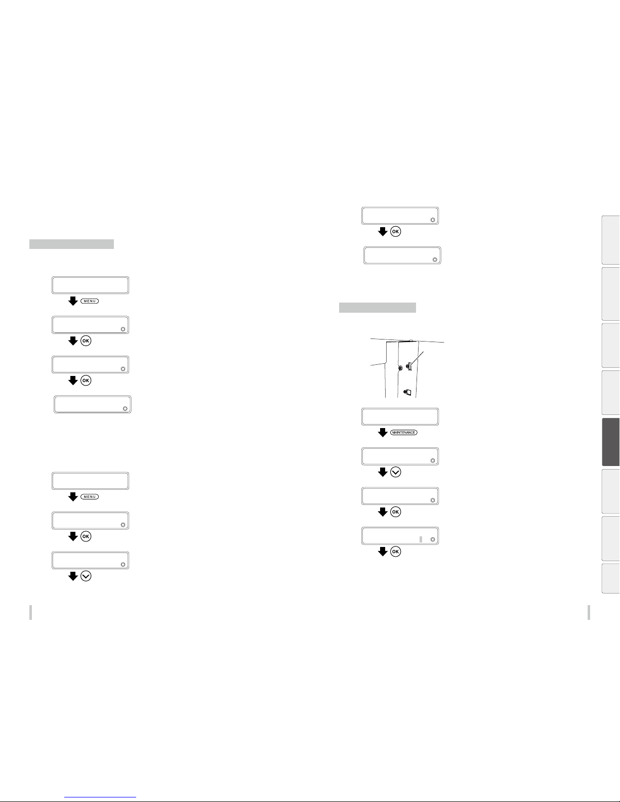
114 115
Advanced operation s Advanced operation s
Check the printer information
Check the remaining ink level
During printing
1
PRINTING...
STANDARD ND BI
Press the MENU key.
2
MENU
2
INK INFORMATION
Press the Down key to select INK
INFORMATION, and then press the OK key.
3
>INK INFORMATION
2
REMAINING INK
Press the OK key.
4
CC: ink color
XXX%: Remaining ink
>>REMAINING INK
2
CC XXX%
When the remaining ink (total ink - used ink) falls under 2%,
LOW is displayed.
Press the Up and Down keys to select the
color whose ink you want to check.
Not during printing
1
PRINTER READY
01: PAPER / 1626mm
Press the MENU key.
2
MENU
2
INFORMATION
Press the OK key.
3
>INFORMATION
2
INK INFORMATION
Press the Down key to select INK
INFORMATION.
3
>>INK INFORMATION
2
REMAINING INK
Press the OK key.
4
CC: ink color
XXX%: Remaining ink
>>>REMAINING INK
2
CC XXX%
When the remaining ink (total ink - used ink) falls under 2%,
LOW is displayed.
Press the Up and Down keys to select the
color whose ink you want to check.
Export printer information
Menu information can be exported in the PDF format to the USB drive.
1
USB port
Insert a USB drive in the USB port.
The FAT32 format is recommended for the USB drive.
2
PRINTER READY
01: PAPER / 1626mm
Press the MAINTENANCE key.
3
MAINTENANCE
2
START MAINTENANCE
Press the Down key to select EXPORT DATA
TO USB.
4
MAINTENANCE
2
EXPORT DATA TO USB
Press the OK key.
5
>EXPORT DATA TO USB
USB DRIVE CONNECT ED?
Press the OK key.
Before printing Loading the media Adjustment Maintenance
Advanced
operations
Troubleshooting Menu tree Appendix
Page 59
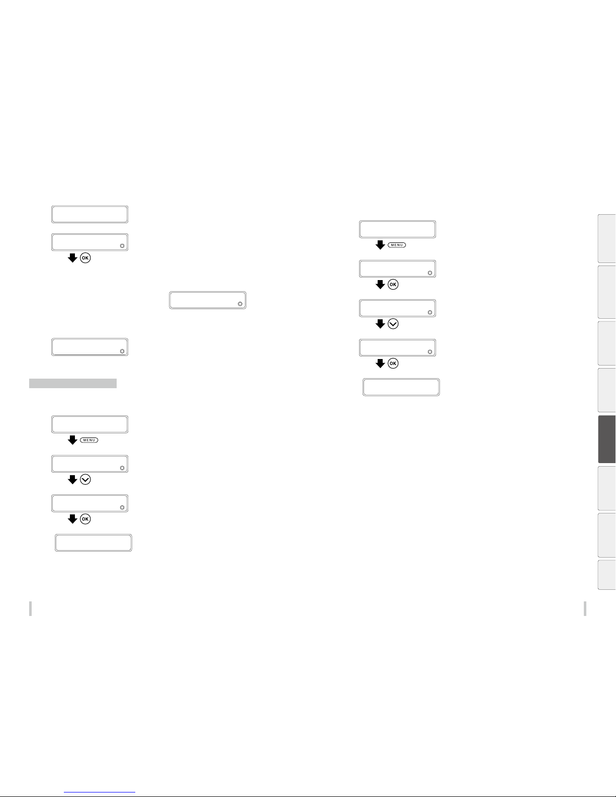
116 117
Advanced operation s Advanced operation s
>EXPORT DATA TO USB
2
EXECUTING
7
>EXPORT DATA TO USB
EXPORT COMPLE TED
EXPORT COMPLETED is displayed when the export
finishes successfully.
Press the OK key.
If the export failed, an error message is displayed.
XX is an error code.
01: Insufficient space on the USB drive
02: The USB drive is write-protected.
>EXPORT DATA TO USB
EXPORT FAILED :X X
8
MAINTENANCE
2
EXPORT DATA TO USB
After the export has finished, the panel display returns to
the previous screen.
Check remaining media length
During printing
1
PRINTING...
STANDARD ND BI
Press the MENU key.
2
MENU
2
INK INFORMATION
Press the Down key to select REMAINING
MEDIA.
3
MENU
2
REMAINING MEDIA
Press the OK key.
4
Displayed in the unit set in the length unit menu.
XX: Preset numb er
NNNNNN: Media name
YYY: Remaining length
>REMAINING MEDIA
2
XX:NNNNNN YYYm
Not during printing
1
PRINTER READY
01: PAPER / 1626mm
Press the MENU key.
2
MENU
2
INFORMATION
Press the Down key to select INFORMATION,
and then press the OK key.
3
>INFORMATION
2
INK INFORMATION
Press the Down key to select REMAINING
MEDIA.
4
>INFORMATION
2
REMAINING MEDIA
Press the OK key.
5
Displayed in the unit set in the length unit menu.
XX: Preset number
NNNNNN: Media name
YYY: Remaining length
>REMAINING MEDIA
2
XX:NNNNNN YYYm
Before printing Loading the media Adjustment Maintenance
Advanced
operations
Troubleshooting Menu tree Appendix
Page 60
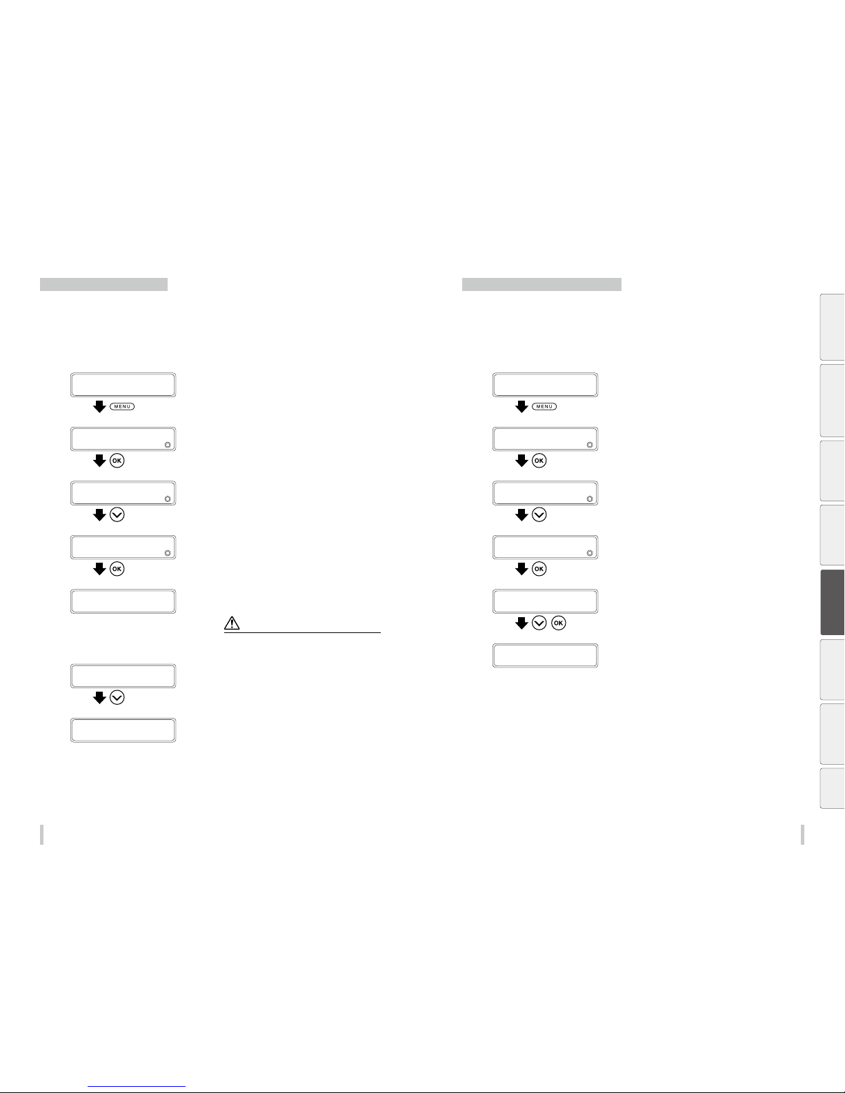
118 119
Advanced operation s Advanced operation s
Check the USB connection status
During printing
The USB connection status cannot be checked during printing.
Check the connection when the printer is not printing.
Not during printing
1
PRINTER READY
01: PAPER / 1626mm
Press the MENU key.
2
MENU
2
INFORMATION
Press the Down key to select INFORMATION,
and then press the OK key.
3
>INFORMATION
2
INK INFORMATION
Press the Down key to select USB INFO.
4
>INFORMATION
2
USB INFO
Press the OK key.
5
>>USB INFO
2
ADDRESS:XXX
The panel displays the USB address.
If the address is different from 000, the address is valid.
Note
If the panel displays the US B address as 000, connect the
USB cable connection once again.
6
>>USB INFO
2
ADDRESS :XXX
Press the Down key to select SPEED.
The printer checks the connection speed.
7
>>USB INFO
2
SPEED :XXXXX
The panel displays the USB connection speed.
The panel should display HIGH-SPEED.
If the panel displays FULL-SPEED, the print process will be
slower.
Check the rmware version on the printer
During printing
The rmware version cannot be checked during printing.
Check the version when the printer is not printing.
Not during printing
1
PRINTER READY
01: PAPER / 1626mm
Press the MENU key.
2
MENU
2
INFORMATION
Press the Down key to select INFORMATION,
and then press the OK key.
3
>INFORMATION
2
INK INFORMATION
Press the Down key to select VERSION INFO.
4
>INFORMATION
2
VERSION INFO
Press the OK key.
5
>VERSION INFO
2
BOOT X.XX
,
Press the Down key to select FIRM WARE, and
then press the OK key.
6
>VERSION INFO
2
FIR MWARE X.X X_Y Y
The panel displays the printer’s firmware version.
Before printing Loading the media Adjustment Maintenance
Advanced
operations
Troubleshooting Menu tree Appendix
Page 61
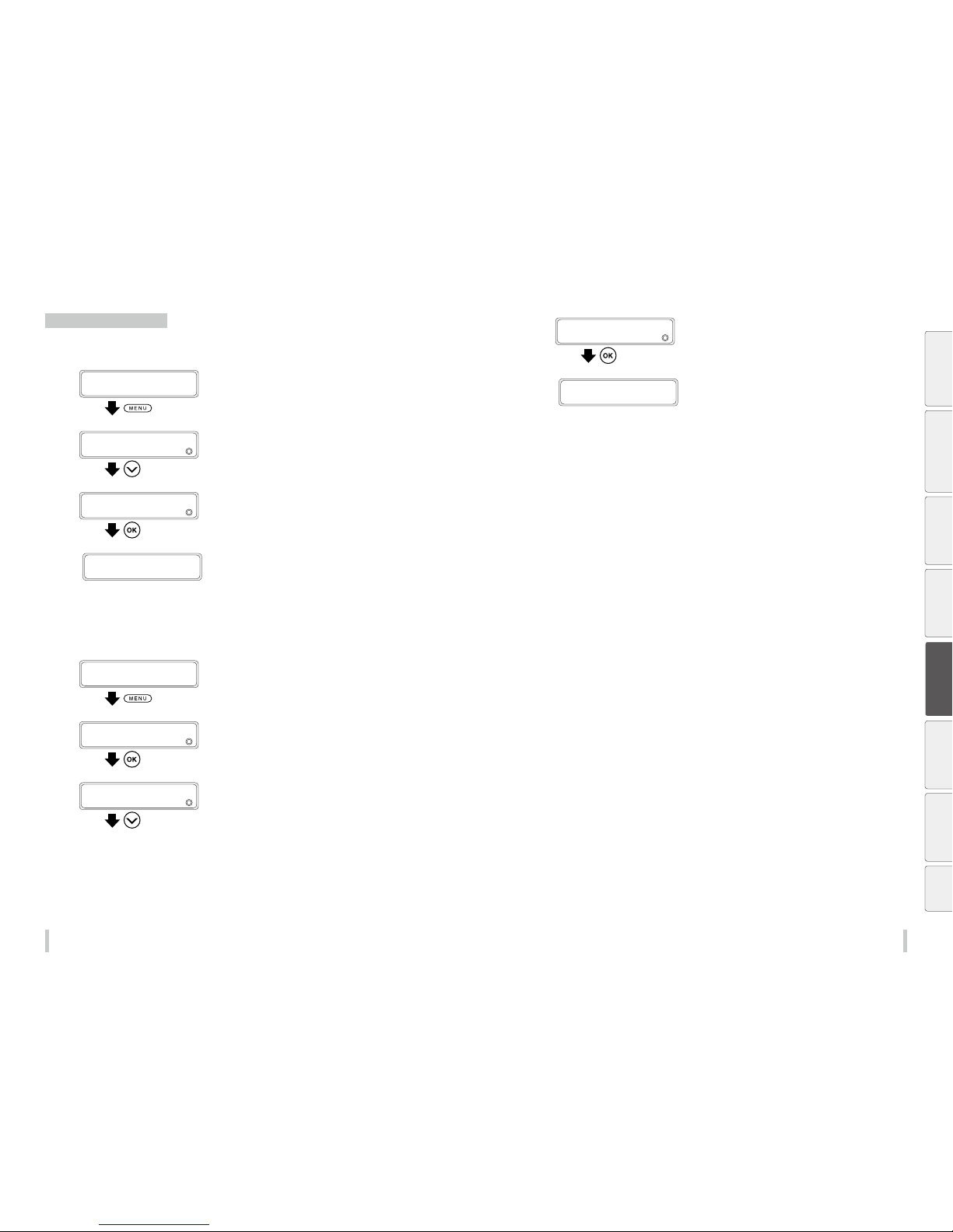
12 0 121
Advanced operation s Advanced operation s
Check the total print length
During printing
1
PRINTING...
STANDARD ND BI
Press the MENU key.
2
MENU
2
INK INFORMATION
Press the Down key to select TOTAL PRINT
LENGTH.
3
MENU
2
TOTAL PRINT LENGTH
Press the OK key.
4
Displayed in the unit set in the length unit menu.
>TOTAL PRINT LENGTH
YYYYYm
Not during printing
1
PRINTER READY
01: PAPER / 1626mm
Press the MENU key.
2
MENU
2
INFORMATION
Press the Down key to select INFORMATION,
and then press the OK key.
3
>INFORMATION
2
INK INFORMATION
Press the Down key to select TOTAL PRINT
LENGTH.
4
>INFORMATION
2
TOTAL PRINT LENGTH
Press the OK key.
5
Displayed in the unit set in the length unit menu.
>TOTAL PRINT LENGTH
YYYYYm
Before printing Loading the media Adjustment Maintenance
Advanced
operations
Troubleshooting Menu tree Appendix
Page 62
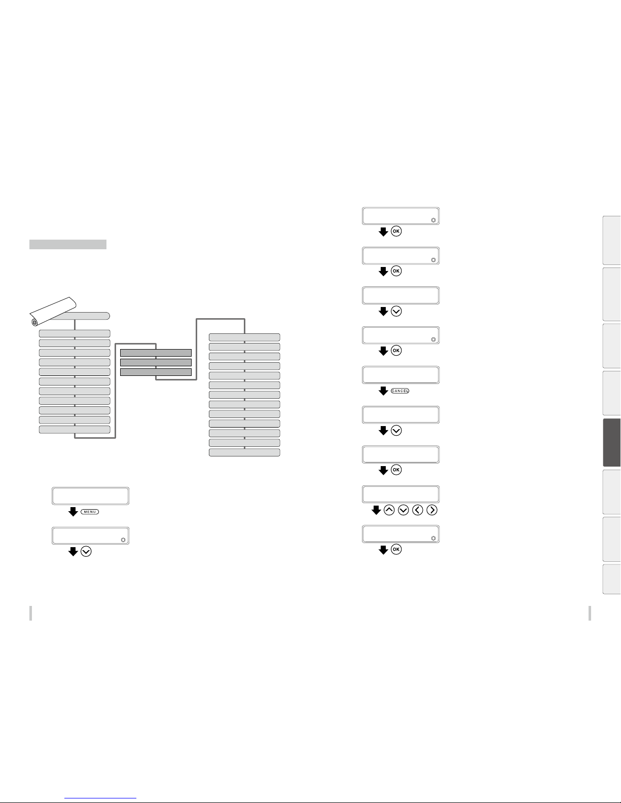
122 12 3
Advanced operation s Advanced operation s
Handle the media
Create a new media preset
You can register 20 media presets in the printer (No.01 to 20).
The parameters in the preset menu are in the order shown below. You can select the number of the preset to edit
with SELECT PRESET NO.
The setting values for the 24 parameters are saved for each preset.
SELECT PRESET NO.
(1) EDIT PRESET NAME
(2) MEDIA ADV PRIORITY
(3) MEDIA ADV VALUE
(4) BIDIR ADJUST 1
(5) BIDIR ADJUST 2
(6) BIDIR ADJUST 3
(7) BIDIR ADJUST 4
(8) HEATER PRIORITY
(9) AFTERHEATER T
(10) PRINTHEATER T
(11) PREHEATER T
DELETE PRESET
PRESET COPY SOURCE
COPY DESTINATION
(12) REMAINING MEDIA
MISC SETTINGS
(13) IONIZER
(14) TUR MODE
(15) MEDIA EDGE GUARDS
(16) SKEW CHECK
(17) COLOR STRIPE
(18) SUCTION FAN POWER
(19) MEDIA ADVANCE MODE
(20) MEDIA BACK MODE
(21) AUTO PH CLEANING
(22) PH REST INTERVAL
(23) PH REST TIME
(24) CARRIAGE SPEED
This example explains how to enter a media advance adjustment value for the media preset number 02.
1
PRINTER READY
01: PAPER / 1626mm
Press the MENU key.
2
MENU
2
INFORMATION
Press the Down key to select EDIT MEDIA
PRESETS.
3
MENU
2
EDIT MEDIA PRESET S
Press the OK key.
4
>EDIT MEDIA PRESET S
2
SELECT PRESET NO.
Press the OK key.
5
>>SELECT PRESET NO.
201g
*01PAP ER
Press the Down key.
6
>>SELECT PRESET NO.
201g
*02Glossy
Press the OK key.
The paper type of the preset changes from 01PAPER to
02Glo ssy.
7
>>SELECT PRESET NO.
201g
*02Glossy
Press the CANCEL key.
You exit the media type selection menu.
8
>EDIT MEDIA PRESET S
2
SELECT PRESET NO.
Press the Down key to select MEDIA ADV
VALUE .
9
>EDIT MEDIA PRESET S
2
MEDIA ADV VALUE
Press the OK key.
10
>>MEDIA ADV VALUE
2
*100.00g100.00%
, , ,
Press the Left and Right keys to select a digit,
and press the Up and Down keys to set a
value.
11
>>MEDIA ADV VALUE
2
*100.00g102.0 0%
Enter the media advance adjustment value
and press the OK key.
Before printing Loading the media Adjustment Maintenance
Advanced
operations
Troubleshooting Menu tree Appendix
Page 63
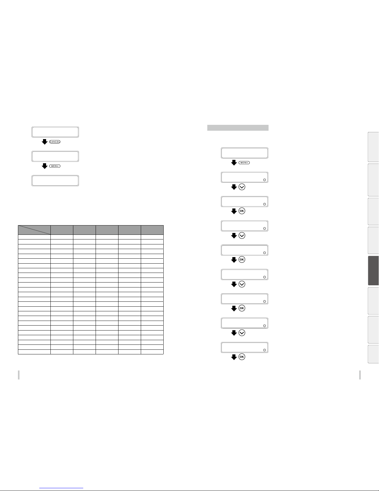
124 12 5
Advanced operation s Advanced operation s
12
>>MEDIA ADV VALUE
2
*102.0 0g102.0 0%
Press the CANCEL key.
13
>EDIT MEDIA PRESET S
2
MEDIA ADV VALUE
Press the MENU key.
PRINTER READY
01: PAPER / 1626mm
Preset media default values
Up to 20 presets (No. 01 to 20) of media can be registered. Media presets can also be deleted or changed. However,
preset No. 01 (PAPER) and the media initially set in the printer cannot be deleted.
For the media preset 01 to 05, the initial values are listed below.
Preset No.
01 02 03 04 05
Setting
EDIT PRESET NAME Paper Glossy Matte B anner BLT_ B
MEDIA ADV PRIORITY DATA SE TT ING DATA SET TIN G DATA SET TI NG DATA SE TT ING DATA S ETT ING
MEDIA ADV VALUE 100.00% 100.00% 100.00% 100.00% 100.00%
BIDIR ADJUST 1 00 00 00 00 00
BIDIR ADJUST 2 00 00 00 00 00
BIDIR ADJUST 3 00 00 00 00 00
BIDIR ADJUST 4 00 00 00 00 00
HEATER PRIORITY DATA SET TIN G D ATA SE TTI NG DATA SE TT ING DATA S ET TIN G DATA SET TIN G
AFTERHEATER T ** ºC 50 ºC 50 ºC 50ºC 50º C
PRINTHEATER T ** º C 40ºC 40º C 40ºC 40ºC
PREHEATER T ** ºC 45º C 45ºC 45ºC 45º C
MISC SETTINGS
REMAINING MEDIA 0m 0m 0m 0m 0m
IONIZER OFF OFF OFF OFF OFF
TUR MODE LOOSE LOOSE LOOSE TENSION TENSION
MEDIA EDGE GUARDS ON ON ON ON ON
SKEW CHECK ON ON ON ON ON
COLOR STRIPE OFF OFF OFF OFF OFF
SUCTION FAN POWER MEDIUM MEDIUM MED IUM LOW LOW
MEDIA ADVANCE MODE FORWARD ONLY FORWARD ONLY FORWARD ONLY FORWARD ONLY FORWARD ONLY
MEDIA BACK MODE ON ON ON ON ON
AUTO PH CLEANING
BEFORE&AFTER PRINT BEFORE&AFTER PRINT BEFORE&AFTER PRINT BEFORE&AFTER PRINT BEFORE&AFTER PRINT
PH REST INTERVAL 0 CYCLES 0 C YCLES 0 CYC LES 0 CYCLE S 0 CYCLES
PH REST TIME 1 SECONDS 1 SECONDS 1 SECONDS 1 SECONDS 1 SECONDS
CARRIAGE SPEED NORMAL NORMAL NORMAL NORMAL NORMAL
*Modify the media advance a djustment value and the bidirectional adjustm ent values to t the media you are using.
Minimize the right and left margins
Deactivate the media edge guards
1
PRINTER READY
01: PAPER / 1626mm
Press the MENU key.
2
MENU
2
INFORMATION
Press the Down key to select EDIT MEDIA
PRESETS.
3
MENU
2
EDIT MEDIA PRESET S
Press the OK key.
4
>EDIT MEDIA PRESET S
2
SELECT PRESET NO.
Press the Down key to select MISC SETTINGS.
5
>EDIT MEDIA PRESET S
2
MISC SETTI NGS
Press the OK key.
6
>>MISC SETTINGS
2
REMAINING MEDIA
Press the Down key to select MEDIA EDGE
GUARDS.
7
>>MISC SETTINGS
2
MEDIA EDGE GUARDS
Press the OK key.
8
>>>MEDIA EDGE GUARDS
2
ON
Press the Down key once.
9
>>>MEDIA EDGE GUARDS
2
OFF
Press the OK key.
Before printing Loading the media Adjustment Maintenance
Advanced
operations
Troubleshooting Menu tree Appendix
Page 64
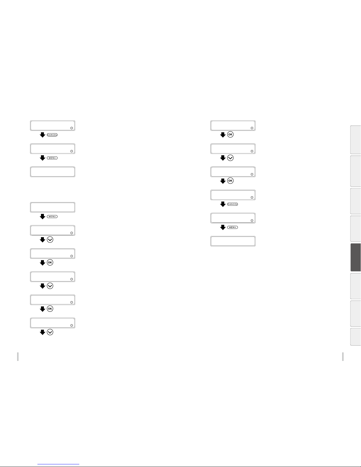
126 12 7
Advanced operation s Advanced operation s
10
>>>MEDIA EDGE GUARDS
2
OFF
Press the CANCEL key.
11
>>MISC SETTINGS
2
MEDIA EDGE GUARDS
Press the MENU key.
PRINTER READY
01: PAPER / 1626mm
Activate the color stripe
1
PRINTER READY
01: PAPER / 1626mm
Press the MENU key.
2
MENU
2
INFORMATION
Press the Down key to select EDIT MEDIA
PRESETS.
3
MENU
2
EDIT MEDIA PRESET S
Press the OK key.
4
>EDIT MEDIA PRESET S
2
SELECT PRESET NO.
Press the Down key to select MISC SETTINGS.
5
>EDIT MEDIA PRESET S
2
MISC SETTI NGS
Press the OK key.
6
>>MISC SETTINGS
2
REMAINING MEDIA
Press the Down key to select COLOR STR IPE.
7
>>MISC SETTINGS
2
COLOR STRIPE
Press the OK key.
8
>>>COLOR STRIPE
2
OFF
Press the Down key once.
9
>>>COLOR STRIPE
2
ON
Press the OK key.
10
>>>COLOR STRIPE
2
ON
Press the CANCEL key.
11
>>MISC SETTINGS
2
COLOR STRIPE
Press the MENU key.
PRINTER READY
01: PAPER / 1626mm
Before printing Loading the media Adjustment Maintenance
Advanced
operations
Troubleshooting Menu tree Appendix
Page 65
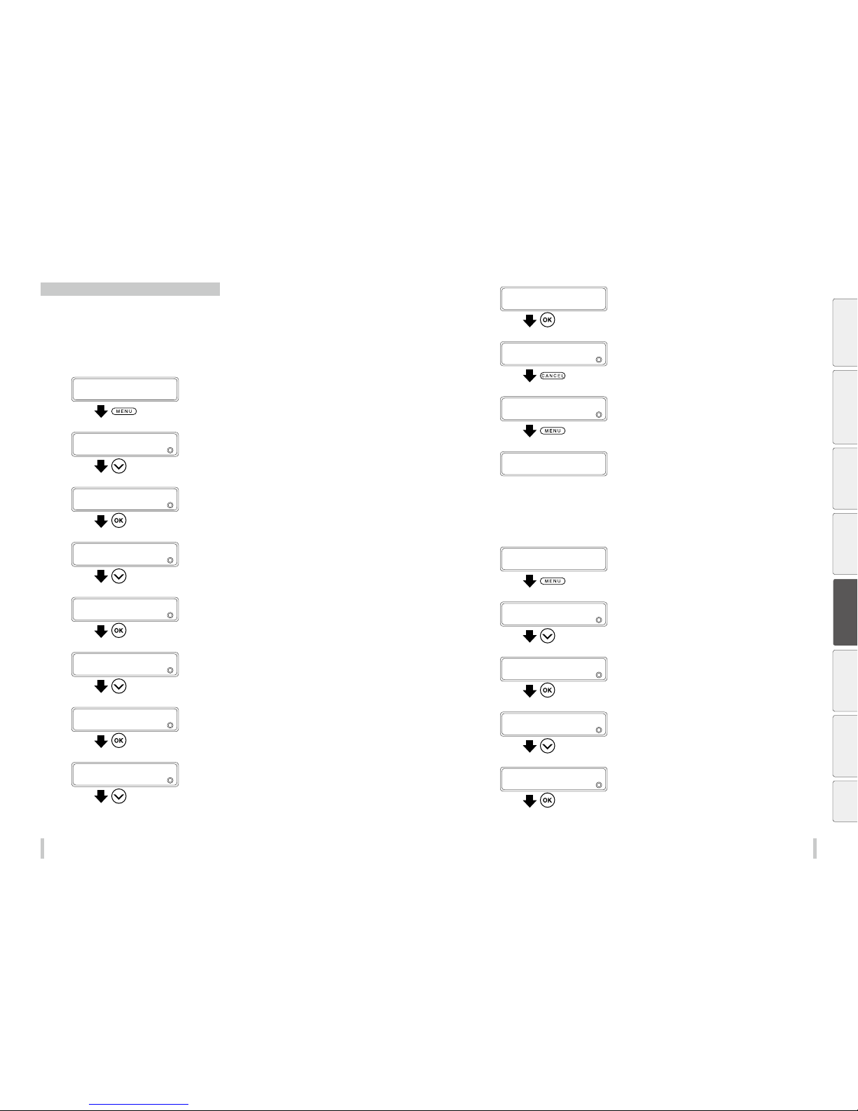
128 12 9
Advanced operation s Advanced operation s
Prevent the media from sticking and wrinkling
Decrease the platen suction fan power
The vacuum pressure applied to the media in the printing zone helps to hold the media down on the platen to keep
the distance from media to print heads constant.
When the media sticks to the platen, set the vacuum pressure to LOW. The LOW vacuum pressure is also eective
when your media is very exible and wrinkles easily.
1
PRINTER READY
01: PAPER / 1626mm
Press the MENU key.
2
MENU
2
INFORMATION
Press the Down key to select EDIT MEDIA
PRESETS.
3
MENU
2
EDIT MEDIA PRESET S
Press the OK key.
4
>EDIT MEDIA PRESET S
2
SELECT PRESET NO.
Press the Down key to select MISC SETTINGS.
5
>EDIT MEDIA PRESET S
2
MISC SETTI NGS
Press the OK key.
6
>>MISC SETTINGS
2
REMAINING MEDIA
Press the Down key to select SUCTION FAN
POWER.
7
>>MISC SETTINGS
2
SUCTION FAN POWER
Press the OK key.
8
>>>SUCTION FAN POWER
2
MEDIUM
Press the Down key once.
9
>>>SUCTION FAN POWER
2
LOW
Press the OK key.
10
>>>SUCTION FAN POWER
2
LOW
Press the CANCEL key.
11
>>MISC SETTINGS
2
SUCTION FAN POWER
Press the MENU key.
PRINTER READY
01: PAPER / 1626mm
Change the media advance mode
Select the media advance mode according to the media used.
1
PRINTER READY
01: PAPER / 1626mm
Press the MENU key.
2
MENU
2
INFORMATION
Press the Down key to select EDIT MEDIA
PRESETS.
3
MENU
2
EDIT MEDIA PRESET S
Press the OK key.
4
>EDIT MEDIA PRESET S
2
SELECT PRESET NO.
Press the Down key to select MISC SETTINGS.
5
>EDIT MEDIA PRESET S
2
MISC SETTI NGS
Press the OK key.
Before printing Loading the media Adjustment Maintenance
Advanced
operations
Troubleshooting Menu tree Appendix
Page 66
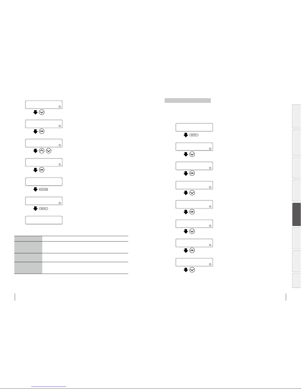
13 0 131
Advanced operation s Advanced operation s
6
>>MISC SETTINGS
2
REMAINING MEDIA
Press the Down key to select MEDIA
ADVANCE MODE.
7
>>MISC SETTINGS
2
MEDIA ADVANCE MODE
Press the OK key.
8
>>>MEDIA ADVANCE MODE
2
FORWARD ONLY
,
Press the Up and Down keys to select an
advance mode.
9
>>>MEDIA ADVANCE MODE
2
BACK & FWD LOW
Press the OK key.
10
>>>MEDIA ADVANCE MODE
2
BACK & FWD LOW
Press the CANCEL key.
11
>>MISC SETTINGS
2
MEDIA ADVANCE MODE
Press the MENU key.
PRINTER READY
01: PAPER / 1626mm
FORWARD ONLY The media is fed in the normal advance direction.
BACK & FWD LOW The m edia is fed in order to prevent it from sticking on the platen. When the
printing starts or when a pause is canceled, the media is fed back and forward to
detach it from the platen.
BACK & FWD HIGH T he media is fed in order to prevent it from sticking on the platen. The media is fed
back and forward to detach it from the platen at each scanning cycle.
FWD LESS WRINKLES Advance feeding sequence to prevent wrinkles on solvent printing coated paper.
If five minutes have elapsed after the end of the last printing, the printer feeds 55
cm of media before starting to print.
Prevent the media from lifting up
The vacuum pressure applied to the media in the printing zone helps to hold the media down on the platen to keep
the distance from media to print heads constant.
When a gap tends to form between the media and the platen, set the vacuum pressure to HIGH.
1
PRINTER READY
01: PAPER / 1626mm
Press the MENU key.
2
MENU
2
INFORMATION
Press the Down key to select EDIT MEDIA
PRESETS.
3
MENU
2
EDIT MEDIA PRESET S
Press the OK key.
4
>EDIT MEDIA PRESET S
2
SELECT PRESET NO.
Press the Down key to select MISC SETTINGS.
5
>EDIT MEDIA PRESET S
2
MISC SETTI NGS
Press the OK key.
6
>>MISC SETTINGS
2
REMAINING MEDIA
Press the Down key to select SUCTION FAN
POWER.
7
>>MISC SETTINGS
2
SUCTION FAN POWER
Press the OK key.
8
>>>SUCTION FAN POWER
2
MEDIUM
Press the Up and Down keys to select HIGH.
Before printing Loading the media Adjustment Maintenance
Advanced
operations
Troubleshooting Menu tree Appendix
Page 67
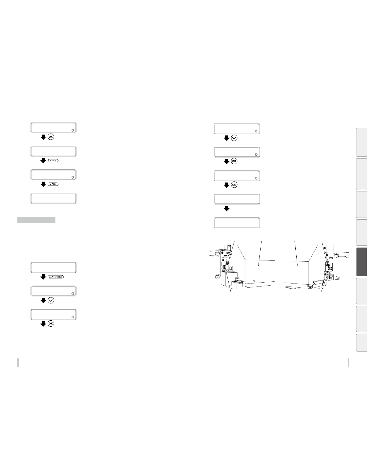
132 13 3
Advanced operation s Advanced operation s
9
>>>SUCTION FAN POWER
2
HIGH
Press the OK key.
10
>>>SUCTION FAN POWER
2
HIGH
Press the CANCEL key.
11
>>MISC SETTINGS
2
SUCTION FAN POWER
Press the MENU key.
PRINTER READY
01: PAPER / 1626mm
Print on a thick media
Change the height of the print heads
Be sure to adjust the height of the print heads when printing on thick media to prevent the print heads from
contacting the media.
Change the print head height depending on the media used with the head up/down mechanism.
On the operation panel enter the print head height adjustment option in the preset menu.
1
PRINTER READY
01: PAPER / 1626mm
Press the MAINTENANCE key.
2
MAINTENANCE
2
START MAINTENANCE
Press the Down key to select PH
MAINTENANCE.
3
MAINTENANCE
2
PH MAINTENANCE
Press the OK key.
4
>PH MAINTENANCE
2
CLEAN FOR STOR AGE
Press the Down key to select ADJUST PH
HEIGHT.
5
>PH MAINTENANCE
2
ADJUST PH HEIGHT
Press the OK key.
6
>>ADJUST PH HEIGHT
2
OK?
Press the OK key.
CARRIAGE IS MOVIN G
PLEASE WAIT
Carriage stops moving.
7
OPEN COVER
PH HEIGHT ADJ
Open the front cover and the maintenance
cover and loosen the two head securing
screws.
Head securing screw Head securing screw
Head up/down mechanism Head up/down mechanismCarriage (left side) Carriage (right side)
Before printing Loading the media Adjustment Maintenance
Advanced
operations
Troubleshooting Menu tree Appendix
Page 68
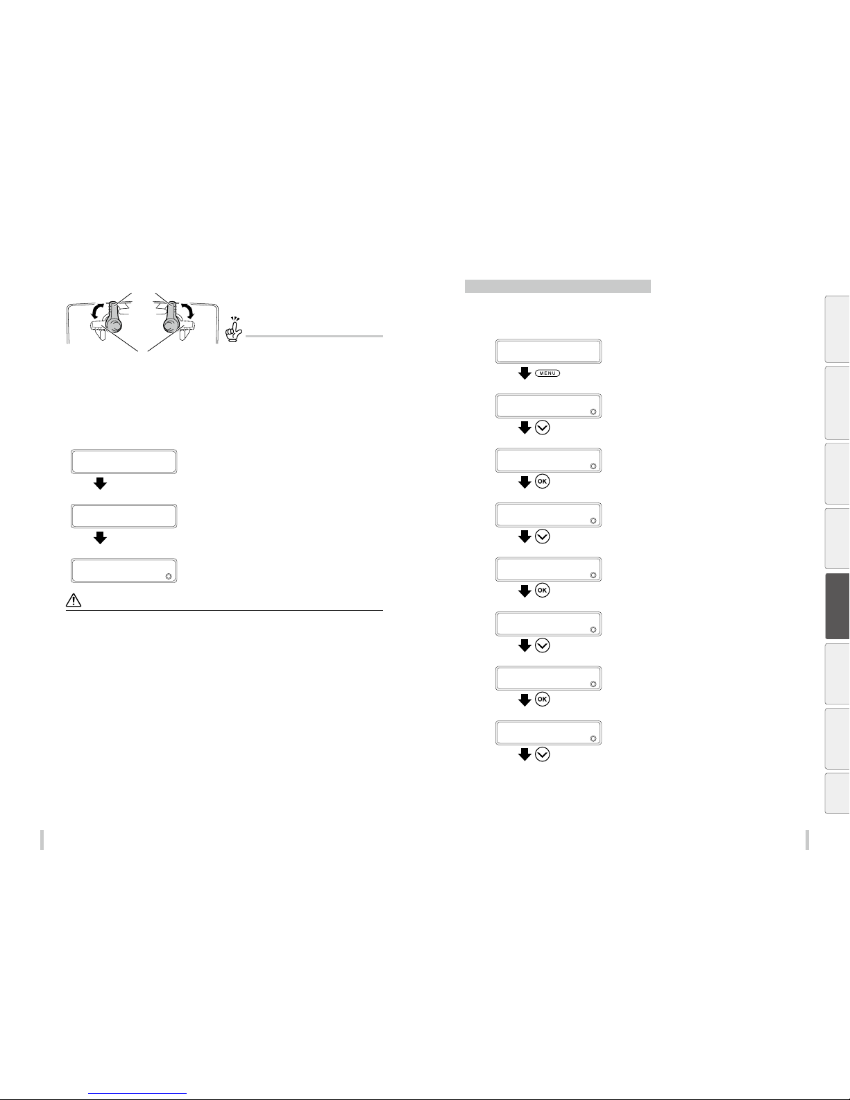
134 13 5
Advanced operation s Advanced operation s
8
High (for thick media)
Normal (for thin (normal thickness) media)
Change the height of print head with the
head up/down mechanism.
TIP
High is 0.5 mm higher than Nor mal.
Generally, Normal is used for gl ossy and matte vinyl
chloride media, and High is us ed for tarpaulin and
FF media. If the media thickn ess exceeds 0.5 mm,
High should be used regard less of the media type.
Use also High even with thin media if it is s everely
wrinkled or contains irre gularities that may touch
the print head.
9
Tighten the two securing screws.
10
ADUST PH HEIGHT
CLOSE COVERS
Close the maintenance cover and the front
cove r.
CARRIAGE IS MOVIN G
PLEASE WAIT
Carriage stops moving.
11
>PH MAINTENANCE
2
ADJUST PH HEIGHT
Notes
Do not move the head up/down mechani sm with the head securing screws ti ghtened. The head up/down mechanism
may break.
When changing the heig ht of the print heads, tighten the hea d securing screws while pushin g lightly the carriage
downward.
After changing the print head height, bidirectional printing may be slightly misaligned. In this case, adjust bidirectional
printing with BIDIR POSITION in the ADJUST menu.
As the gap between th e side plate of the printer and the ca rriage is narrow, if it is hard to reach the he ad up/down
mechanism and the head se curing screws, move the carriag e to the right (or the left) manually.
Conrm that the right and lef t head securing screws are ti ghtened. If the carriage moves w ith the head securing screws
loosened, they may stri ke the media or edge guards, cau sing poor image quality and d amage to the printer.
Always operate the two head u p/down mechanisms at the same time and ma ke sure that they are set to the same
position.
During adjustment of th e head height, a warning beep w ill be issued.
Prevent the ink from spreading over the printout
If the ink tends to spread over the printout, set the ionizer to ON.
Generally do not let the ionizer setting to ON but change the setting depending on the characteristics of the media.
1
PRINTER READY
01: PAPER / 1626mm
Press the MENU key.
2
MENU
2
INFORMATION
Press the Down key to select EDIT MEDIA
PRESETS.
3
MENU
2
EDIT MEDIA PRESET S
Press the OK key.
4
>EDIT MEDIA PRESET S
2
SELECT PRESET NO.
Press the Down key to select MISC SETTINGS.
5
>EDIT MEDIA PRESET S
2
MISC SETTI NGS
Press the OK key.
6
>>MISC SETTINGS
2
REMAINING MEDIA
Press the Down key to select IONIZER.
7
>>MISC SETTINGS
2
IONIZER
Press the OK key.
8
>>>ION IZER
2
OFF
Press the Up and Down keys to select ON.
Before printing Loading the media Adjustment Maintenance
Advanced
operations
Troubleshooting Menu tree Appendix
Page 69
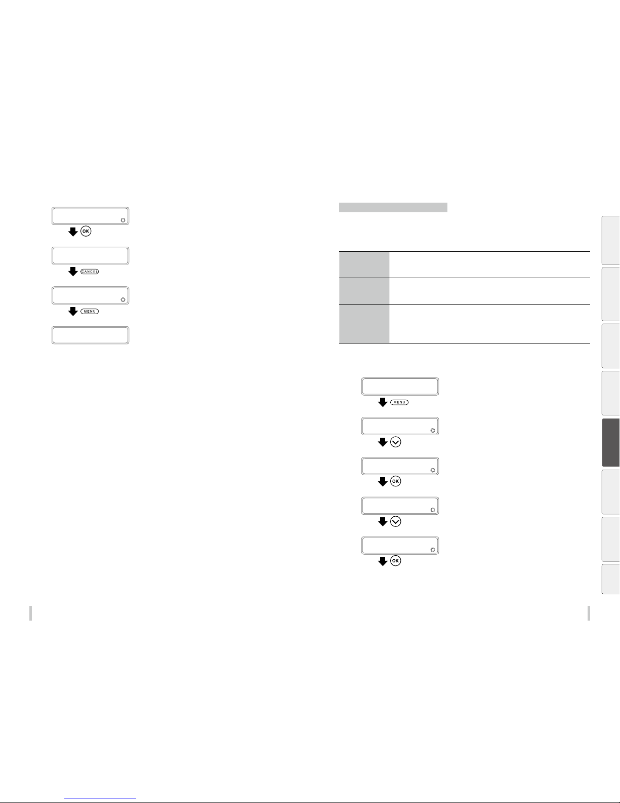
136 13 7
Advanced operation s Advanced operation s
9
>>>ION IZER
2
ON
Press the OK key.
10
>>>ION IZER
2
ON
Press the CANCEL key.
11
>>MISC SETTINGS
2
IONIZER
Press the MENU key.
PRINTER READY
01: PAPER / 1626mm
Change the automatic cleaning timing
To ensure the print heads’ good condition, the printer performs the automatic cleaning. The cleaning mode can be
specied depending on the media preset. Select BEFORE&DURING PRNT or BEFORE& AFTER PRINT depending on
the media characteristics.
BEFORE&AFTER
PRINT
Based on the previous printing operations, the printer performs the automatic cleaning when
starting and completing the print operation.
BEFORE&DURING
PRNT
Based on the previous printing operations, the printer performs the automatic cleaning when
starting the print operation or during printing .
After cleaning, the printer resumes printing if it was interrupted.
OFF Automatic cleaning is not performed. We recommend using this mode when printing
continuously several data files on media with which differences between printouts will be
noticeable if automatic cleaning is performed between two files.However, since cleaning is not
performed automatically, determine suitable timing to execute cleaning manually. Noz zles will
clog more frequently if cleaning is not performed for a long time.
The following procedure explains how to set BEFORE&DURING PRNT for automatic cleaning in the media preset
No.2.
1
PRINTER READY
01: PAPER / 1626mm
Press the MENU key.
2
MENU
2
INFORMATION
Press the Down key to select EDIT MEDIA
PRESETS.
3
MENU
2
EDIT MEDIA PRESET S
Press the OK key.
4
>EDIT MEDIA PRESET S
2
SELECT PRESET NO.
Press the Down key to select MISC SETTINGS.
5
>EDIT MEDIA PRESET S
2
MISC SETTI NGS
Press the OK key.
Before printing Loading the media Adjustment Maintenance
Advanced
operations
Troubleshooting Menu tree Appendix
Page 70
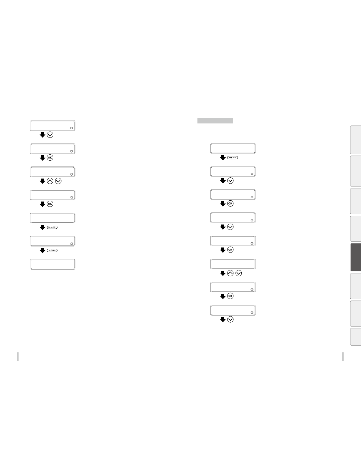
13 8 139
Advanced operation s Advanced operation s
6
>>MISC SETTINGS
2
REMAINING MEDIA
Press the Down key to select AUTO PH
CLEANING.
7
>>MISC SETTINGS
2
AUTO PH CLEANING
Press the OK key.
8
>>>AUTO PH CLEANING
2
*OFF
,
Press the Up and Down keys to select
BEFORE&DURING PRNT.
9
>>>AUTO PH CLEANING
2
BEFORE&DURING PRNT
Press the OK key.
10
>>>AUTO PH CLEANING
2
*BEFORE&DURING PRNT
Press the CANCEL key.
11
>>MISC SETTINGS
2
AUTO PH CLEANING
Press the MENU key.
PRINTER READY
01: PAPER / 1626mm
Copy a media preset
The following procedure explains how to copy the parameters registered in media preset No. 2 to media preset No.
10.
1
PRINTER READY
01: PAPER / 1626mm
Press the MENU key.
2
MENU
2
INFORMATION
Press the Down key to select EDIT MEDIA
PRESETS.
3
MENU
2
EDIT MEDIA PRESET S
Press the OK key.
4
>EDIT MEDIA PRESET S
2
SELECT PRESET NO.
Press the Down key to select PRESET COPY
SOURCE.
5
>EDIT MEDIA PRESET S
2
PRESET COPY SOURCE
Press the OK key.
6
>>PRESET COPY SOURCE
2
*01:PA PER
,
Press the Up and Down keys to select a copy
source.
Only numbers for media presets that already exist are
displayed.
7
>>PRESET COPY SOURCE
2
*02:Glossy
Press the OK key.
8
>EDIT MEDIA PRESET S
2
PRESET COPY SOURCE
Press the Down key to select COPY
DESTINATION.
Before printing Loading the media Adjustment Maintenance
Advanced
operations
Troubleshooting Menu tree Appendix
Page 71
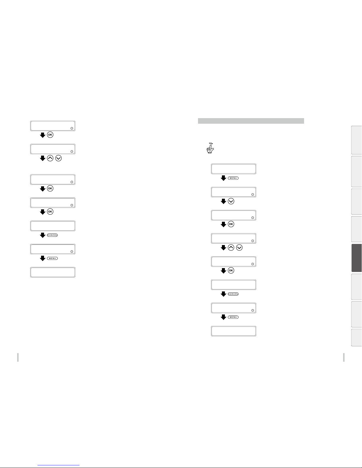
14 0 141
Advanced operation s Advanced operation s
9
>EDIT MEDIA PRESET S
2
COPY DESTINATION
Press the OK key.
10
>>COPY DESTINATION
202g
*02:Glossy
,
Press the Up and Down keys to select a copy
destination.
Copy destination numbers 01 to 20 are displayed.
If the number on the right is followed by an asterisk (*), the
preset displayed already contains media type information.
11
>>COPY DESTINATION
202g
10:TYPE10
Press the OK key.
12
>>COPY DESTINATION
202g
10:TYPE10 O K?
Press the OK key.
13
>>COPY DESTINATION
202g
10:TYPE10
Press the CANCEL key.
14
>COPY DESTINATION
2
COPY DESTINATION
Press the MENU key.
PRINTER READY
01: PAPER / 1626mm
Change the type of the preset media without reloading the media
The following procedure explains how to change from Paper media type in preset No. 1 to Glossy media type in
preset No. 2.
The media type par ameter (02:Glossy here) is called automatica lly when starting printing, to gether with the 24
parameters set for each m edia preset.
1
PRINTER READY
01: PAPER / 1626mm
Press the MENU key.
2
MENU
2
INFORMATION
Press the Down key to select CHANGE
PRESET.
3
MENU
2
CHANGE PRESET
Press the OK key.
4
>CHANGE PRESET
201g
01:PAP ER
,
Press the Up and Down keys to select the
media preset number to set.
5
>CHANGE PRESET
201g
02:Glossy
Press the OK key.
6
>CHANGE PRESET
204g
02:Glossy
Press the CANCEL key.
7
>MENU
2
CHANGE PRESET
Press the MENU key.
PRINTER READY
02:Glossy/1626mm
Before printing Loading the media Adjustment Maintenance
Advanced
operations
Troubleshooting Menu tree Appendix
Page 72
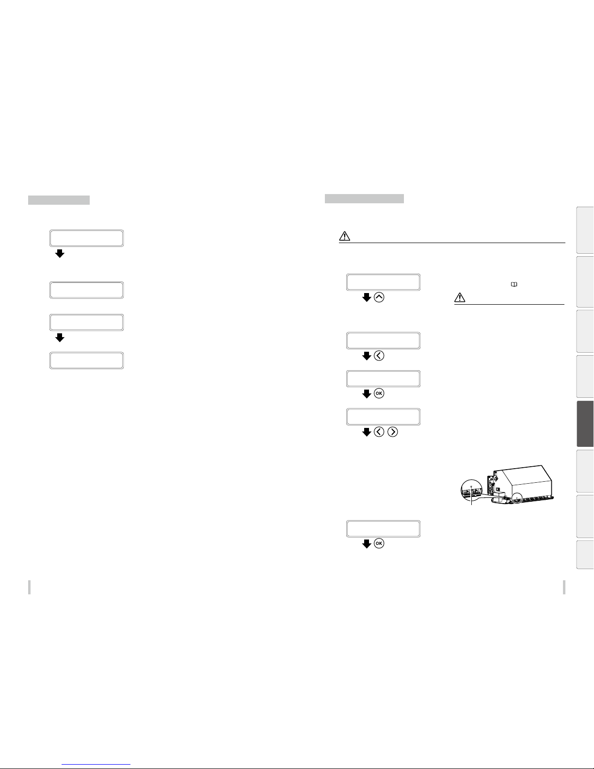
142 143
Advanced operation s Advanced operation s
Feed or rewind media
Feeding and rewinding operations can be executed in the online state (idle mode).
1
PRINTER READY
01: PAPER / 1626mm
Press and hold the Up or Down ke y.
Press and hold the Up or Down key.
To feed media, press the Down key.
To rewind media, press the Up key.
2
When the Down key is pressed.
FEEDING MEDIA...
When the Up key is pressed.
BACKFEEDING MEDIA…
Release the Up or Down key.
Release the Up or Down key.
The printer stops feeding or rewinding media, and the
display returns to online state.
PRINTER READY
01: PAPER / 1626mm
Move the print start position
Move the print start position (origin), to start printing on your preferred position.
After printing, rewind the roll, and with this function you can print an image in the blank area.
CAUTI ON
Complete this operation a s quickly as possible. Othe rwise the print heads may dr y, which may cause ink ejection failur e. In
such a case perform a c leaning.
1
BACKFEEDING MEDIA…
Rewind the media.
See Feed or rewind media on p age 142.
CAUTI ON
Rewind the media afte r the printout has completely
dried. If the media is re wound while the printout is not
suciently dry, the printo ut may be damaged.
2
PRINTER READY
01: PAPER / 1626mm
Press the Left key.
3
START ORIGIN SETTING
OK?
Press the OK key.
4
ORIGIN SETTING
CARRIAGE IS MOVIN G
,
The carriage moves and the origin setting function is
activated.
Move the carriage with the Left or Right key
to the position to be set as the origin.
Align the s mark at the bottom left of the carriage cover’s
front panel with the origin of the next printout.
Origin
5
SET ORIGIN
*OK?
Press the OK key to set the origin.
The carriage returns, and the printer enters online state and
becomes ready to print.
Before printing Loading the media Adjustment Maintenance
Advanced
operations
Troubleshooting Menu tree Appendix
Page 73
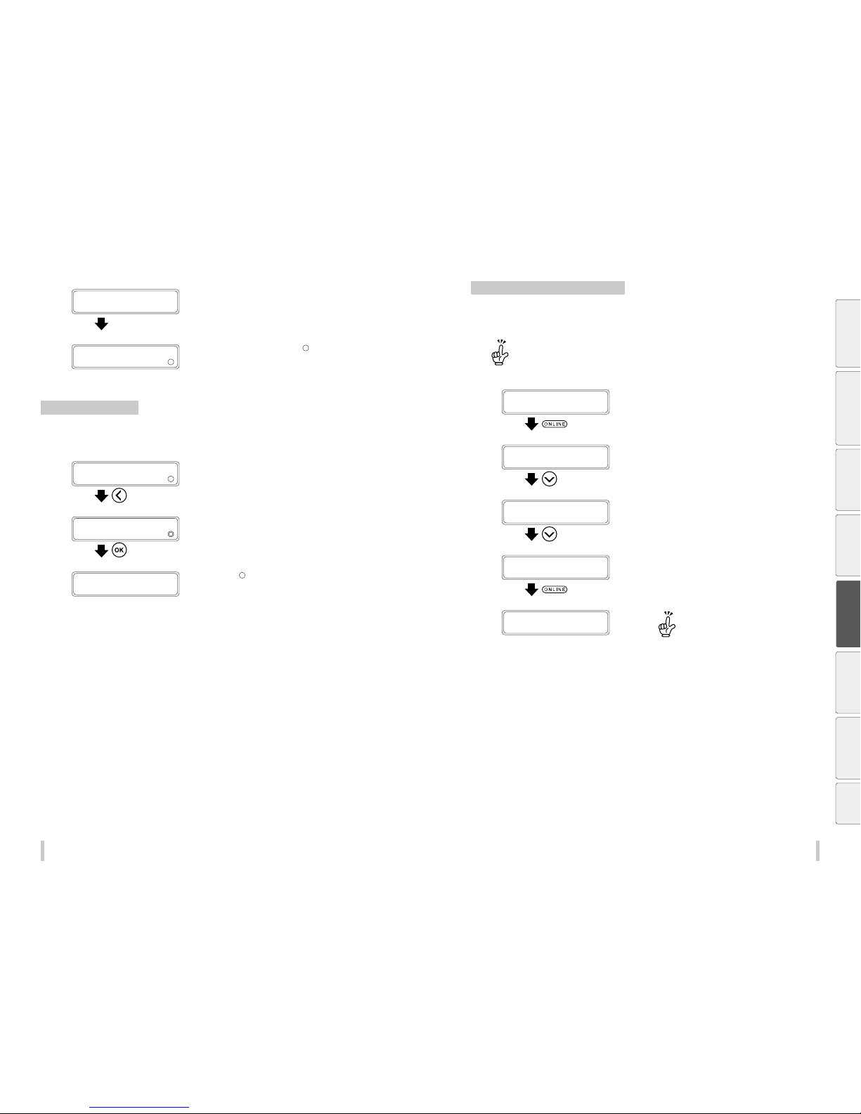
14 4 14 5
Advanced operation s Advanced operation s
SETTING ORIGIN...
PLEASE WAIT
PRINTER READY
01: PAPER / 1626mm
During origin setting mode, a symb ol is displayed next to
the paper width value.
Exit origin setting mode
To cancel an origin that has been set, reinstall the media, or exit the origin setting mode following the procedure
belo w.
1
PRINTER READY
01: PAPER / 1626mm
Press the Left key when the printer is online
in origin setting mode.
2
CANCEL ORIGIN
OK?
Press the OK key to exit origin setting mode.
3
PRINTER READY
01: PAPER / 1626mm
The symbol disappears .
Adjust the head margin before printing
Advance or rewind the media during the preheating time before printing to adjust the margin to the previous
printout.
Once printing (scan) has starte d, this function cannot
be used for the current job.
1
PREHEATING...
STANDARD ND UNI
Press the ONLINE key during the preheating
time before printing.
2
PRINTER IN PAUSE
01: PAPER / 1626mm
• • •
The printer enters pause mode. Keep the
Down key pressed.
3
FEEDING MEDIA...
Release the Down key.
Release the Down key to stop feeding the
media.
4
PRINTER IN PAUSE
01: PAPER / 1626mm
Press the ONLINE key to resume printing.
5
PREHEATING...
STANDARD ND UNI
Press the Up key to rewind the media.
Before printing Loading the media Adjustment Maintenance
Advanced
operations
Troubleshooting Menu tree Appendix
Page 74
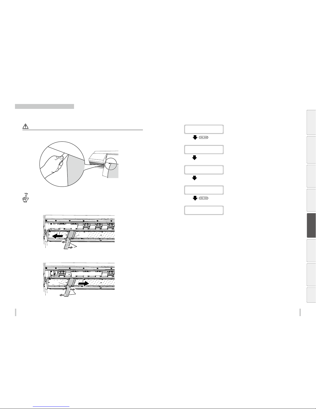
146 147
Advanced operation s Advanced operation s
Reinstall the edge guards during printing
When operate the seat part of the edge guard, it can be adjusted without opening the front cover, if the edge
guards are not correctly placed on the media edges, or if adjust the position of the edge guard.
CAUTI ON
Do not make the adjustment wh en the carriage passes above the e dge guards.
If the edge guards o r the media touch the print heads s urfaces, it may cause clogge d nozzles or a malfuncti on.
Bend the edge guards to slide th em smoothly.
<To slide the edge guards to the left>
Edge guard moving direction
Pivot
Directions of strength (bend the guard in
the counter-clockwise direction)
<To slide the edge guards to the right>
Edge guard moving direction
Pivot
Directions of strength (bend the guard
in the clockwise direction)
In pause mode during print, the front cover can be opened and closed without canceling the print job.
If the edge guards are not correctly placed on the media edges, or if the foreign matter is present on the media
feeding path, put the printer in pause, open the front cover, and reset the edge guards or remove the foreign matter.
1
PRINTING...
STANDARD ND UNI
Press the ONLINE key during printing.
2
PRINTER IN PAUSE
01: PAPER / 1626mm
Open the front cover
The printer enters pause mode. Open the
fro nt cov er.
3
CLOSE COVERS
Close the front cover
Close the cover to return to the printer pause
dis play.
4
PRINTER IN PAUSE
01: PAPER / 1626mm
Press the ONLINE key to resume printing.
5
PRINTING...
STANDARD ND UNI
Before printing Loading the media Adjustment Maintenance
Advanced
operations
Troubleshooting Menu tree Appendix
Page 75
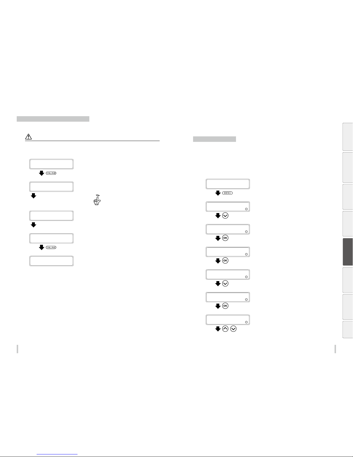
14 8 14 9
Advanced operation s Advanced operation s
Remove some media wrinkles during printing
If the media wrinkles during printing (online mode), put the printer in pause mode to be able to release the grip.
CAUTI ON
Some wrinkles can be r emoved by releasing the the pressu re roller (lifting the lever) bu t this may also decrease the print
quality as the media may sl ip.
1
PRINTING...
STANDARD ND UNI
Press the ONLINE key during the preheating
time before printing.
2
PRINTER IN PAUSE
01: PAPER / 1626mm
Lift the pressure rolle r lever.
After entering pause mode, lift the pressure
roller lever.
When lifting the lever, place your han d on the media
to prevent it from slipping.
3
LOWER THE LEVER
Lower the pressure roller lever.
Lower the pressure roller lever and the panel
returns to the pause mode display.
4
PRINTER IN PAUSE
01: PAPER / 1626mm
Press the ONLINE key to resume printing.
5
PRINTING...
STANDARD ND UNI
To change the printer’s basic settings
Turn the warning beep o
Normally, the printer emits a warning beep when an error occurs. However, the warning beep can be turned o for
the three following cases.
- When the print heads are not covered by the caps (during daily maintenance operations, print head
height adjustment, or when a media jam occurs)
- When a media take-up error occurs
- When the ink runs out or ink cartridges are not installed
1
PRINTER READY
01: PAPER / 1626mm
Press the MENU key.
2
MENU
2
INFORMATION
Press the Down key to select SETTING.
3
MENU
2
SETTING
Press the OK key.
4
>SETTING
2
SYSTEM
Press the OK key.
5
>>SYSTEM
2
SUBSCRIPTION CO DE
Press the Down key to select WARNI NG
SOUND.
6
>>SYSTEM
2
WARNING SOUND
Press the OK key.
7
>>>WARNING SOUND
2
PH UNCAPPED
,
Press the Up and Down keys to select the
type of the warning sound to change.
Before printing Loading the media Adjustment Maintenance
Advanced
operations
Troubleshooting Menu tree Appendix
Page 76
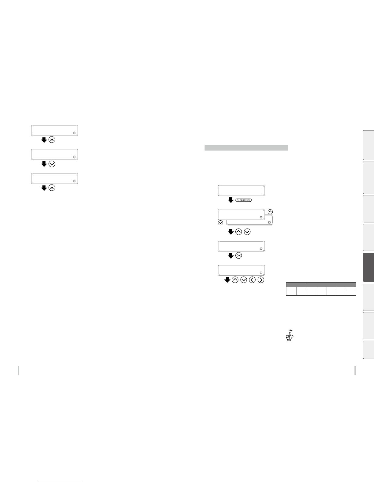
15 0 151
Advanced operation s Advanced operation s
8
>>>WARNING SOUND
2
INK ERRORS
Press the OK key.
9
>>>>INK ERRO RS
2
ON
Press the Down key to select OFF.
10
>>>>INK ERRO RS
2
OFF
Press the OK key.
Cleaning options
Perform cleaning only for the specied print head
In the printer, the six or seven print heads are classied into the following three groups. Whether or not to perform
cleaning can be set for each group. (Cleaning is set to on for each group by default.)
Head group 1: Lc and Lm
Head group 2: C, Y, and K
Head group 3: M (6-color printer) / M and Gy (7-color printer)
1
PRINTER READY
01: PAPER / 1626mm
Press the PH.RECOVE RY key.
2
2
STRONG
PH RECOVERY
2
NORMAL
,
Press the Up and Down keys to select the
cleaning option.
3
PH RECOVERY
2
NORMAL
Press the OK key.
4
>NORMAL
2
PRINT HEAD:1234567
, , ,
Select the print heads to clean.
The correspondence between the ink colors and the print
head numbers is shown in the table below.
Head group 1 Head group 2 Head group 3
Lc Lm C Y K M Gy
1 2 3 4 5 6 7
(1) Press the Le ft and Right keys to select the print head
number.
(2) Then press th Down and Up keys to display or hide the
number. Display it to clean the print head, or hide it not
to clean the print head.
Changing the setting for o ne head in a group
changes the setting for a ll the other heads in the
group.
Before printing Loading the media Adjustment Maintenance
Advanced
operations
Troubleshooting Menu tree Appendix
Page 77
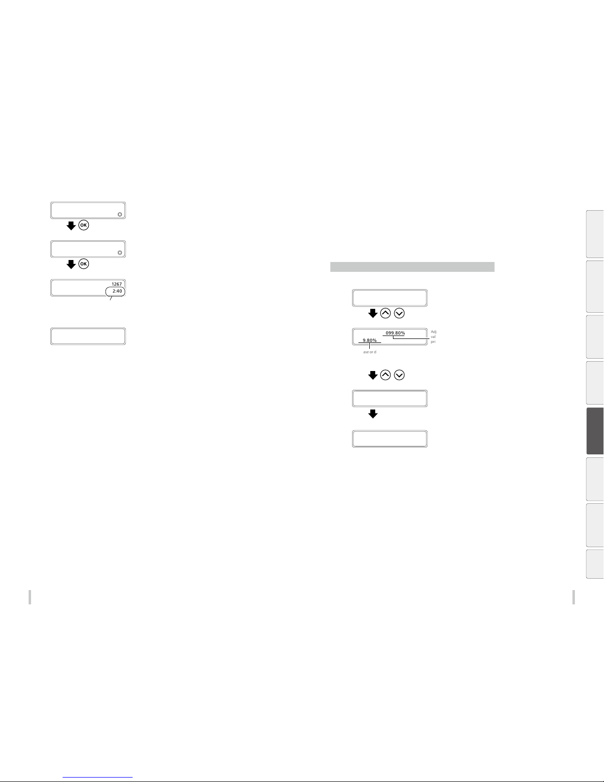
152 153
Advanced operation s Advanced operation s
5
>NORMAL
2
PRINT HEAD:12 67
Press the OK key.
In the example to the left, the print heads Lc and Lm, and M
and Gy will be cleaned.
6
>NORMAL 1267
BOTTLE IS EMPT Y?
Press the OK key.
Check visually that the waste ink bottle is not full.
PH RECOVERING 1267
REQUIRED TIME 2:40
The time is counted down every ten seconds.
Cleaning starts.
Print head cleaning takes several minutes.
When the cleaning starts, the required time is displayed and
the time is counted down every 10 seconds.
7
PRINTER READY
01: PAPER / 1626mm
The printer enters the online mode.
When the cleaning finishes, the printer enters the online mode.
Controlling the media advance
adjustment value
Change the media advance adjustment value during printing
1
PRINTING...
STANDARD ND BI
,
Press the Up or Down key while PRINTING...
is displayed.
2
FINE ADJ VAL:099.80%
2
099.8 0%
Adjustment
value when
printing starts
ncrease or decrease the value by 0.01% with the Up and
Down keys.
(Setting range: 97.00% to 106.00%)
,
Press the Up and Down keys to modify the
adjustment value.
The changed value is applied immediately af ter change.
The adjustment value displayed when the print started
does not change until the print finishes.
3
FINE ADJ VAL:099.80%
2
099. 96%
three seconds
The changed value is registered as the adjustment value
and will be applied for the next print.
The panel display of the adjustment value during printing
returns automatically to the previous screen if no keys are
pressed for three seconds.
PRINTING...
STANDARD ND BI
Before printing Loading the media Adjustment Maintenance
Advanced
operations
Troubleshooting Menu tree Appendix
Page 78
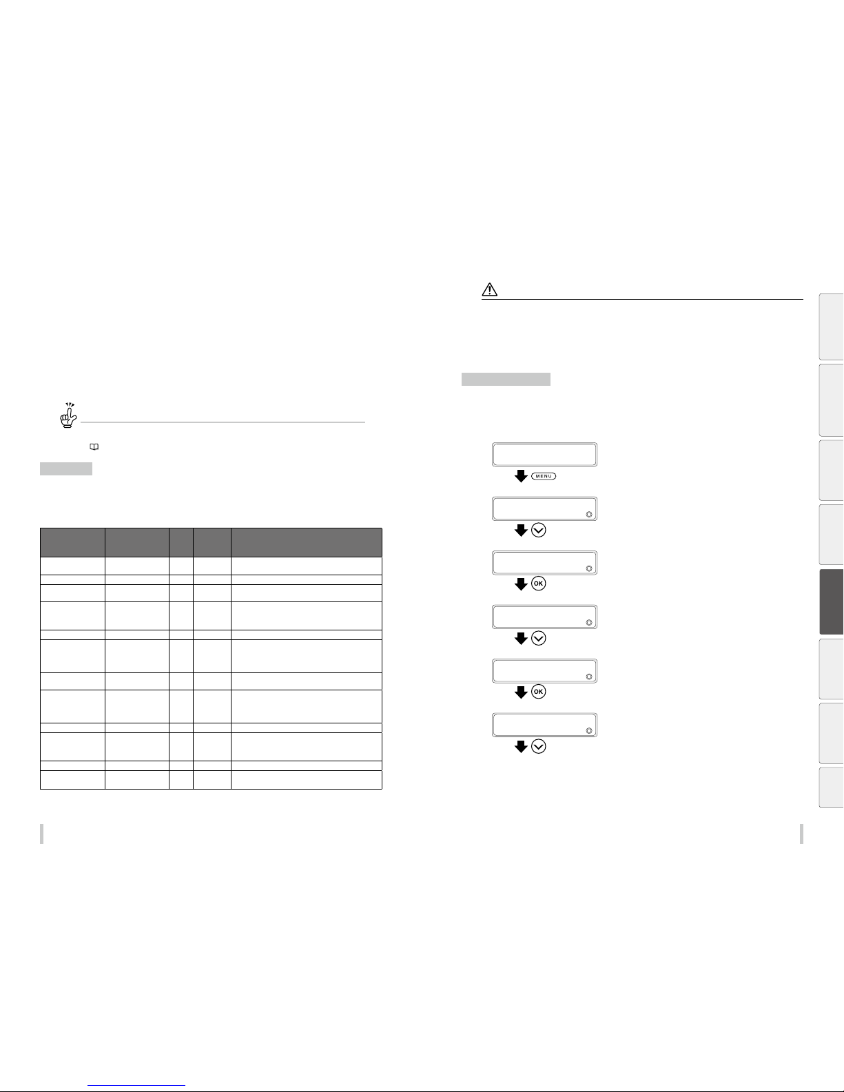
154 155
Advanced operation s Advanced operation s
Print conditions
Twelve print modes are available on the printer, including dierent density levels for the same resolution.
You can also select two speeds for the carriage in each of the 12 print modes.
Select print conditions to achieve the productivity and quality that match the media and the application.
Generally use the printer in Standard print mode with Normal carriage speed.
Use the other mode to prioritize productivity or quality.
If you have changed the print mode...
Depending on the media , the media advance adjustment value m ay change for each mode.
Determine the media adv ance adjustment value manually if bandi ng or other problems appear on the pr intout.
(
page 59)
Print modes
Set the print mode for your desired resolution, number of passes, and density.
The lower the resolution and number of passes, the higher the productivity.
Increasing the resolution and number of passes the enhances the print quality reduces the visible grains.
Print mode Resolution
Number
of
passes
Maximum
density
(When the
STANDARD is 1)
Description
DRAFT 36 0 dpi x 180 dpi x DDP 3 1 Fastest print mode. Use this mo de when prioritizing
productivity.
FAST PRODUCTION 360 dpi x 360 dpi x DDP 4 1 Mode that prioritizes pro ductivity over quality.
PRODUCTION 360 dpi x 360 dpi x DDP 6 1 Mode that slightly prioritizes produc tivity compared to
standard mode.
PRODUCTION / HIGH
DENSITY
360 dpi x 360 dpi x DDP 6 1.5 The high-density mode that prioritizes productivity.
The ink may takes time to dry as a large quantity o f ink is used.
Consequently do not use the TUR unit with this mo de.
STANDARD 540 dpi x 360 dpi x DDP 6 1 T his is the standard mode. Generally use this mode.
STANDARD / HIGH
DENSITY
540 dpi x 360 dpi x DDP 6 2 Productivity is more pri oritized in this mode than in high-
density high quality mode.
The ink may takes time to dry as a large quantity o f ink is used.
Consequently do not use the TUR unit with this mo de.
QUALIT Y 540 dpi x 540 dpi x DDP 9 1.1 Mode that slightly prioritizes quality compared to standard
mode.
QUALITY / HIGH
DENSITY
540 dpi x 540 dpi x DDP 9 1.9 Produc tivity is slightly more prioritized in this mode th an in
high-density high qualit y mode.
The ink may takes time to dry as a large quantity o f ink is used.
Consequently do not use the TUR unit with this mo de.
HIGH QUALITY 720 dpi x 720 dpi 12 1 Mode that achieves high-res olution quality.
HIGH QUALITY / HIGH
DENSITY
720 dpi x 720 dpi 12 2 Generally use this mode to print in hig h density.
MAX QUA LITY 900 dpi x 90 0 dpi 15 1.5 Mo de that achieves the best quality in high resolutio n.
MAX QUALITY / HIGH
DENSITY
900 dpi x 900 dpi 15 3.1 Mode that achieves the best quality in high resoluti on and
high density.
*DDP: Means Dynamic Dot Printi ng which is a technology used to print with dots of d ierent sizes. Small dots are used to reduce the visi ble
grains and large dots are used to in crease the density.
Notes
The recommended mo des are STANDARD to print in normal densit y and HIGH QUALITY / HIGH DEN SITY to print in high
density.
Use the other modes a ccording to your needs for prod uctivity and quality.
Printing in HIGH DENSI TY uses large quantity of i nk. Sometimes it may cause the i nk to blur, ink drying problems, o r take-
up problems.
In such cases, red uce the printing speed.
Set the carriage speed
You can set the carriage to NORMAL or SLOW.
Normally, set the speed to NORMAL. Select SLOW to obtain a better resolution and a more precise print.
(The carriage speed cannot be changed from the RIP soft ware. Use panel operations or CP_ Manager)
1
PRINTER READY
01: PAPER / 1626mm
Press the MENU key.
2
MENU
2
INFORMATION
Press the Down key to select EDIT MEDIA
PRESETS.
3
MENU
2
EDIT MEDIA PRESET S
Press the OK key.
4
>EDIT MEDIA PRESET S
2
SELECT PRESET NO.
Press the Down key to select MISC SETTINGS.
5
>EDIT MEDIA PRESET S
2
MISC SETTI NGS
Press the OK key.
6
>>MISC SETTINGS
2
REMAINING MEDIA
Press the Down key to select CARRIAGE
SPEED.
Before printing Loading the media Adjustment Maintenance
Advanced
operations
Troubleshooting Menu tree Appendix
Page 79
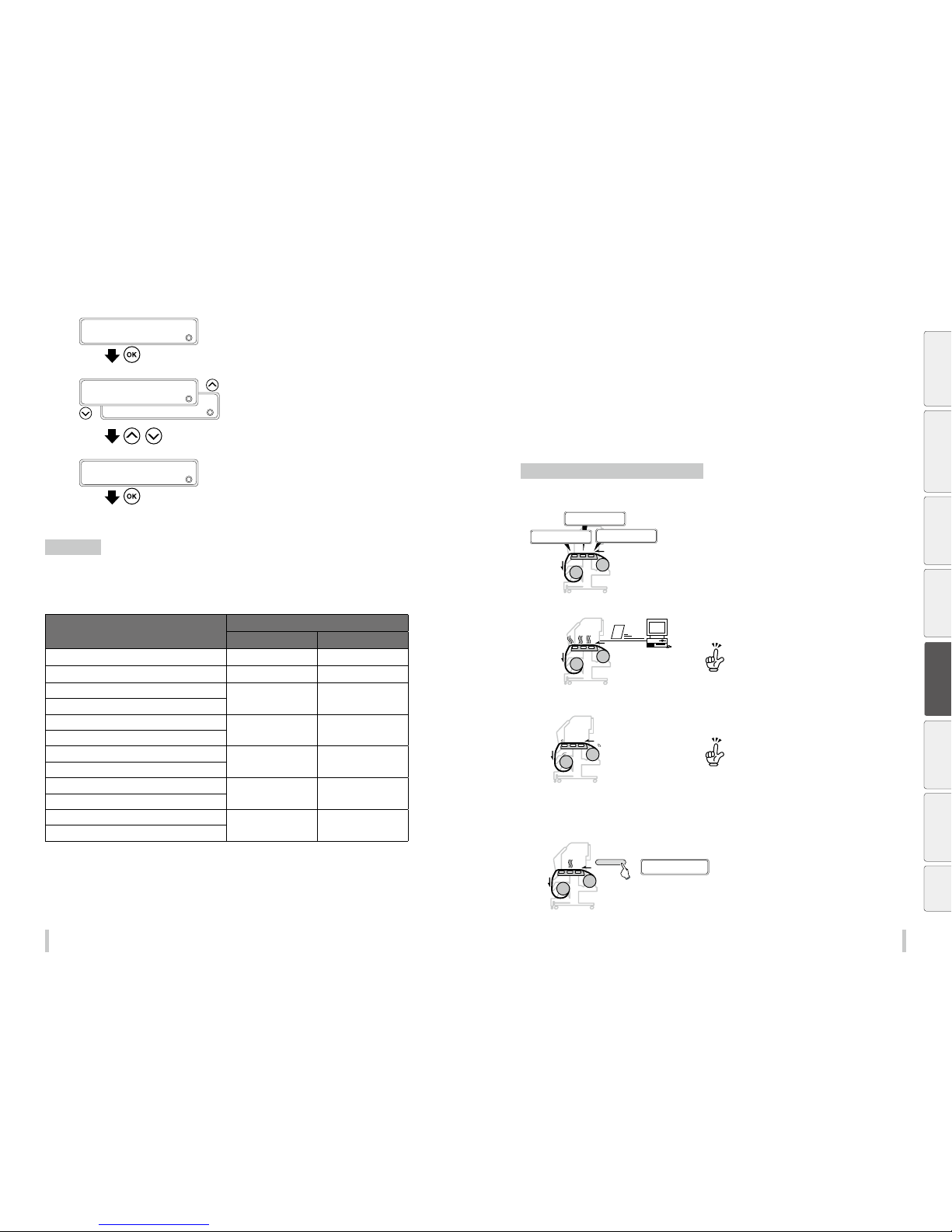
156 157
Advanced operation s Advanced operation s
7
>>MISC SETTINGS
2
CARRIAGE SPEED
Press the OK key.
8
2
SLOW
>>>CA RRIAGE SPE ED
2
NORMAL
,
Press the Up and
Down
keys to select
NORMAL
or
SLOW
.
9
>>>CA RRIAGE SPE ED
2
*SLOW
Press the OK key.
SLOW is set in the example on the left.
Print speed
The print speed depends on the print mode and the carriage speed. Print speeds are shown in the table below.
The real print speed may be slower than the indicated values depending on factors such as the media width.
Print speeds of the IP-6620 *1
Print mode
Carriage speed
NORMAL S LOW
DRAFT
66.5 m
2
/h 40.6 m2/h
FAST PRODUCTION
49.7 m
2
/h 30.4 m2/h
PRODUCTION
33.1 m
2
/h 20.2 m2/h
PRODUCTION / HIGH DENSITY
STANDARD
23.9 m
2
/h 14. 2 m2/h
STANDARD / HIGH DENSITY
QUALITY
16.0 m
2
/h 9.5 m2/h
QUALITY / HIGH DENSITY
HIGH QUALITY
9.2 m
2
/h 5.4 m2/h
HIGH QUALITY / HIGH DENSITY
MAX QUALITY
6.0 m
2
/h 3.5 m2/h
MAX QUALITY / HIGH DENSITY
*1 The indicated speed values are when printing full width on a media of 1626 mm (64 inches) in width.
Adjust the heaters temperatures
Each heater initial value is set in the media preset menu. These values are automatically set for the heaters
temperatures.
Therefore, normally the heater control menu is not required.
The heater control menu is used to:
- Complete the temperature ne adjustment during the print operation; or
- Conrm the current heater temperature
Procedure to set the heaters temperatures
(1) The heaters are in standby at the initial temperature
registered with the media used.
>>AFTERHEATER T
*50→50ºC
◎
>>PRINTHEATER T
*40→40ºC
◎
>>PREHEATER T
*45→45ºC
◎
When a media type is selected af ter installing the media, initial
temperature values of each heater for the selected media type are
displayed on the menu.
(2) Heating starts after receiving the data from the RIP
software.
RIP data
When the heaters temperatures are set with the print and job data
from the RIP software, the temperatures on the heater control
menu are overwritten by the temperatures from the RIP.
To use the initial temperatures set on the o peration panel
rather than the temperature s et with the RIP, set HEATER
PRIORITY in the me dia preset menu to PANEL SETTING.
(3) When the heaters temperatures have almost reached
the set temperatures, the print operation starts.
When the current temperatures of the afterheater, printheater,
and preheater reach a temperature of 1ºC lower than the set
temperature, the printer starts printing.
The heaters maximum set te mperatures are as follows.
Afterheater: 55ºC, Printh eater: 55ºC, Preheater: 55ºC
Even after the print is complete d, the temperatures
changed during this procedur e remain as the heaters setup
temperatures, until the media is ins talled again or the printer
is turned o.
However, the heater temperature set tings in the media
preset menu are not changed .
(4) Changing the heaters temperatures during the print
operation.
■■
45 50 45ºC
Aft 40 +50 45Pre
HEATER
During the print operation the heaters temperatures may be
changed by specifying set temperatures in the heater control
menu.
Before printing Loading the media Adjustment Maintenance
Advanced
operations
Troubleshooting Menu tree Appendix
Page 80
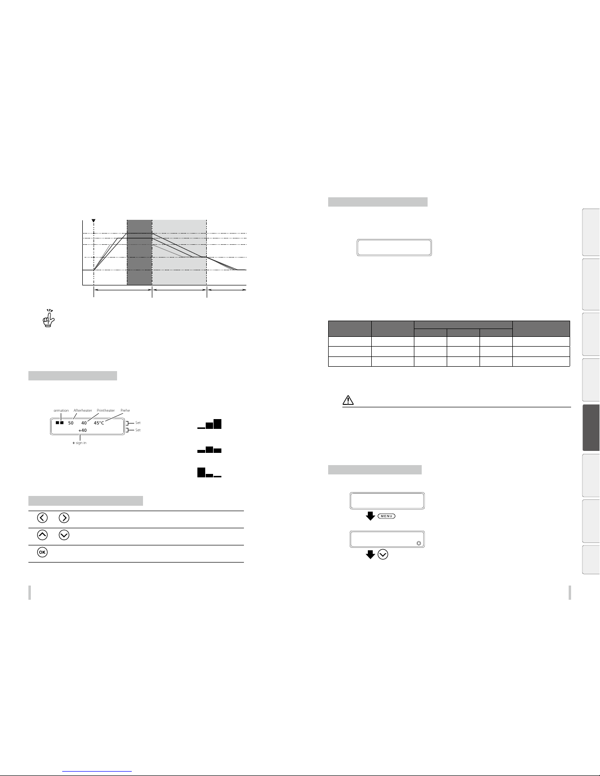
158 15 9
Advanced operation s Advanced operation s
The heater temperature control system for printing
The Printer receives the RIP data.
Printheater set temperature
Preheater set temperature
Afterheater set temperature
Standby set temperature
Ambient temperature
Print
Standby time
(Time)
(Temperature)
Set temperature maintained Standby temperature maintained Temperature control stop
The heaters are in standby at th e temperatures below.
Preheater: 35 ºC
Printheater: 35 ºC
Afterheater: 35 ºC
However, the heaters temperatures ab ove are lowered to the set temperatures if th e set temperatures are lower than
the standby temperatures .
Display the heater control menu
Press the HEATER key to display the heater control menu.
2nn
50 40 45°C
Aft 40 +40 45Pre
Heater operating
information
Afterheater
The + sign indicates that
the heater is heating.
Printheater Preheater
Set temperature
Set temperature
Heater operating information
- Force heating ON:
- Normal operation:
- Heater temporarily OFF:
Key operations in the heater control menu
and key s Change the digit (select the target of the operations)
and key s Change the heater temperature or the heater operation.
key S ets the heater on or off.
Exit the heater control menu display
Press the HEATER key while the heater control menu is displayed.
When the heater control menu display ends automatically
HEATER DISPLAY ENDED
If no keys are input for 30 seconds while the heater control menu is displayed, the message HEATER DISPLAY
ENDED appears automatically for two seconds and then the heater control menu display ends. While this message
is displayed, no key input is eective.
Heater preset temperature for each media
The heater preset temperatures for each media type are listed below. Preset the heater temperature according to
the media you use.
Media Media type
Recommended heater temperature setting
Print mode
Afterheater Printheater Preheater
Glossy vinyl Glossy 50 ºC 40º C 45º C NORMAL, bidirectional
Matte vinyl Ma tte 50
ºC 40º C 45º C NORMAL, bidirectional
Banner Banner 50
ºC 40º C 45º C NORMAL, bidirectional
We recommend that the preheater, the printheater, and the afterheater be set to a temperature lower than 50ºC,
45ºC, and 50ºC respectively.
Notes
When the printheater tem perature is set very high, th e ink fusion on the media is improve d, however this may cause
the media to wrinkles o r the printout to be very matte. Ad just heater temperatures accor ding to the media type and th e
environmental temperature.
When the printheater tem perature is too high, the printe r may print at low speed to ensure stab le print quality.
Set the preheater/afterheater temperatures 5ºC higher than the printheater temperature. Incorrect temperature balance
between preheate r/afterheater and printheater may caus e the media to wrinkle.
Setting the printhe ater temperature too high may lead to m issing dots on the printout.
Set the heater preset temperature
1
PRINTER READY
02:Glossy/1626mm
Press the MENU key.
2
MENU
2
INFORMATION
Press the Down key to select EDIT MEDIA
PRESETS.
Before printing Loading the media Adjustment Maintenance
Advanced
operations
Troubleshooting Menu tree Appendix
Page 81
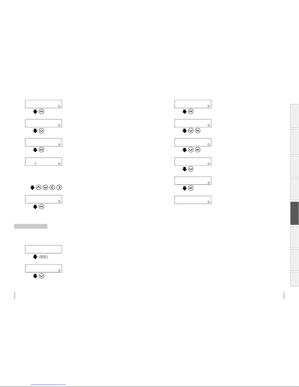
160 161
Advanced operation s Advanced operation s
3
MENU
2
EDIT MEDIA PRESET S
Press the OK key.
4
>EDIT MEDIA PRESET S
2
SELECT PRESET NO.
Press the Down key to select AFTERHEATER T.
5
>EDIT MEDIA PRESET S
2
AFTERHEATER T
Press the OK key.
6
Z: Registration mark (A registration mark * is displayed if the
media preset is registered)
XX: Temperature currently set
YY: Temperature after the change
>>AFTERHEATER T
2
ZXXgYY°C
, , ,
Enter the temperature.
Press the Left and Right keys to select a digit,
and press the Up and Down keys to set a
value.
7
>>AFTERHEATER T
2
ZXXgYY°C
Press the OK key.
Select the standby time
Select the time to maintain the standby set temperature of the heater (including the time for transition to the
standby set temperature) after printing.
1
PRINTER READY
02:Glossy/1626mm
Press the MENU key.
2
MENU
2
INFORMATION
Press the Down key to select SETTING.
3
MENU
2
SETTING
Press the OK key.
4
>SETTING
2
MEDIA HEATER SET.
,
Press the Down key to select MEDIA HEATER
SET. , and then press the OK key.
5
>>MEDIA HEATER SET.
2
STANDBY TIME
,
Press the Down key to select STANDBY TIME,
and then press the OK key.
6
>>>STAND BY TIME
2
30 minutes
Press the Up and Down keys to set the
standby time.
7
>>>STAND BY TIME
2
60 minutes
Press the OK key.
8
>>>STAND BY TIME
2
60 minutes
Before printing Loading the media Adjustment Maintenance
Advanced
operations
Troubleshooting Menu tree Appendix
Page 82
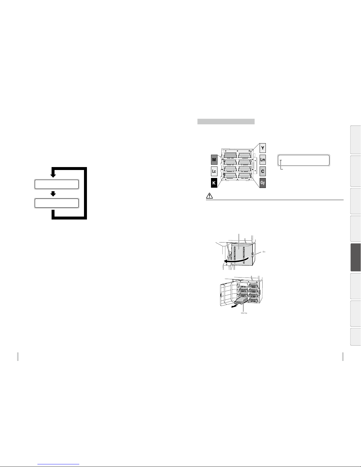
162 163
Advanced operation s Advanced operation s
Out of ink while printing
You can replace ink cartridges while printing without suspending the print operation.
When an ink cartridge is empty, the ink LED goes o. You are advised to follow the message instructions.
1
Ink LED goes o.
2
PRINTING...
NORMAL ND BI
OPEN INK BOX COVER
REPLACE Y CARTRIDGE
The message appears to prompt you to
replace the ink cartridge.
3
Open the ink box cover, and replace the ink
cartridge.
See Instal l and replace an ink cartri dge on page
165.
Install and replace an ink cartridge
When installing ink trays, be sure to insert each tray into its correct slot position in the ink box.
Note that an ink tray position is decided depending on its ink color.
REMOVE
Y INK CARTRIDGE
LCD message
Ink color
CAUTI ON
Do not remove ink trays in the foll owing cases. Otherwi se, ink may spill in the printer depe nding on its state, which may
damage the printer.
• The printer is not tur ned on because the power was inte rrupted or because the circu it breaker is o.
• An error other than i nk end has occurred.
Do not touch the contact p oint on the ink cartridge’s plate .
1
Ink box cover
Knob
Push the knob of the ink box cover to open
the ink box.
2
Ink tray
Conrm the color of the ink cartridge to
be replaced, and pull its ink tray out of the
printer.
Before printing Loading the media Adjustment Maintenance
Advanced
operations
Troubleshooting Menu tree Appendix
Page 83
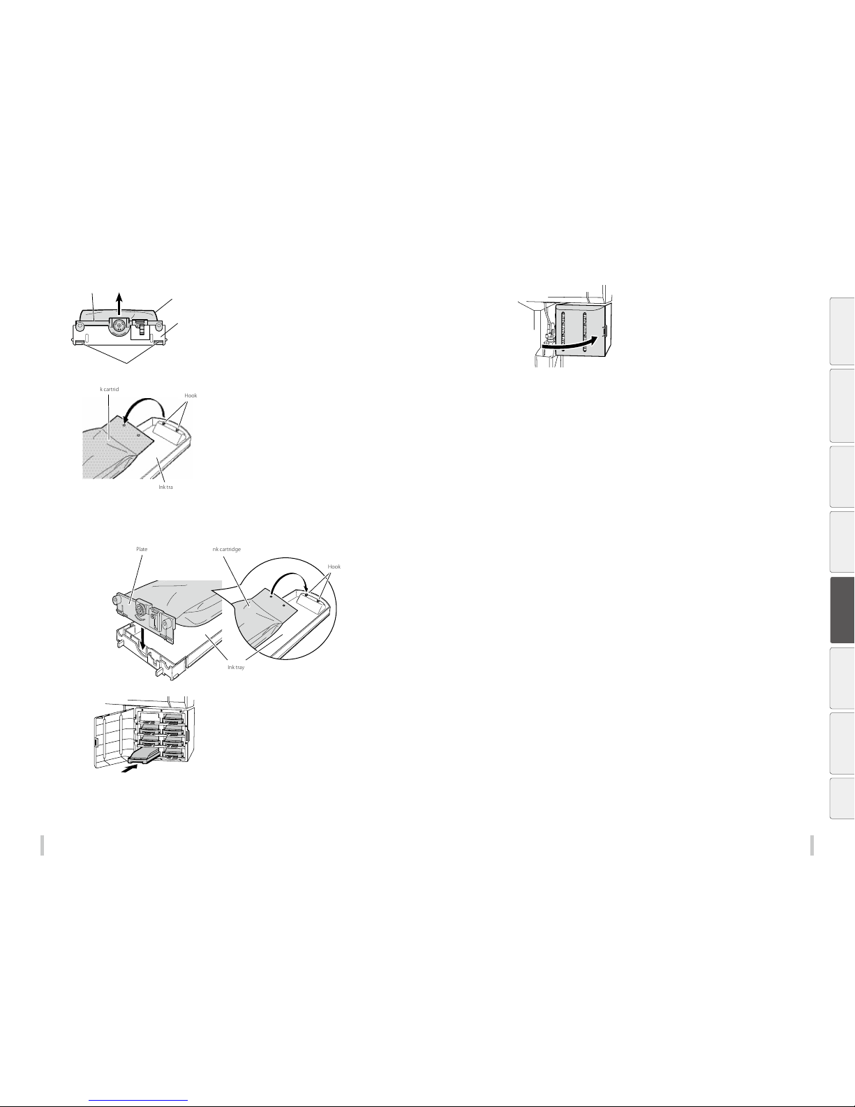
164 165
Advanced operation s Advanced operation s
3
Plate
Push the two claws
Ink tray
Ink cartridge
(1)
If no ink cartridge is installed on the ink tray, go to the step 4.
Remove the empty ink cartridge from the ink
tray.
(1) Push the t wo claws at the lower part of the the ink
cartridge's plate, and pull up the plate.
(2)
Ink cartridge
Hook
Ink tray
(2) Rem ove the ink cartridge from the hook of the ink tray.
4
Take a new ink cartridge out of the package and set it on the ink tray.
Hook the two holes (1) at the ink cartridge end on the ink tray’s two protrusions. Then insert the ink cartridge plate into the
ink tray until you hear a click (2).
New ink cartridgePlate
Ink tray
Hook
(1)
(2)
5
Insert the ink tray into the slot in the printer.
Insert the ink tray as far as it goes.
6
Close the ink box cover.
7
Conrm that the ink cartridge has been successfully replaced.
- When the replacement is successfully completed, the printer returns to the online or offline state.
- If the replacement is not completed, an error message appears. Retry the replacement procedure beginning from
step
1
.
- The print operation is per formed even during the ink cartridge replacement, as far as ink remains in the subcartridge.
Before printing Loading the media Adjustment Maintenance
Advanced
operations
Troubleshooting Menu tree Appendix
Page 84
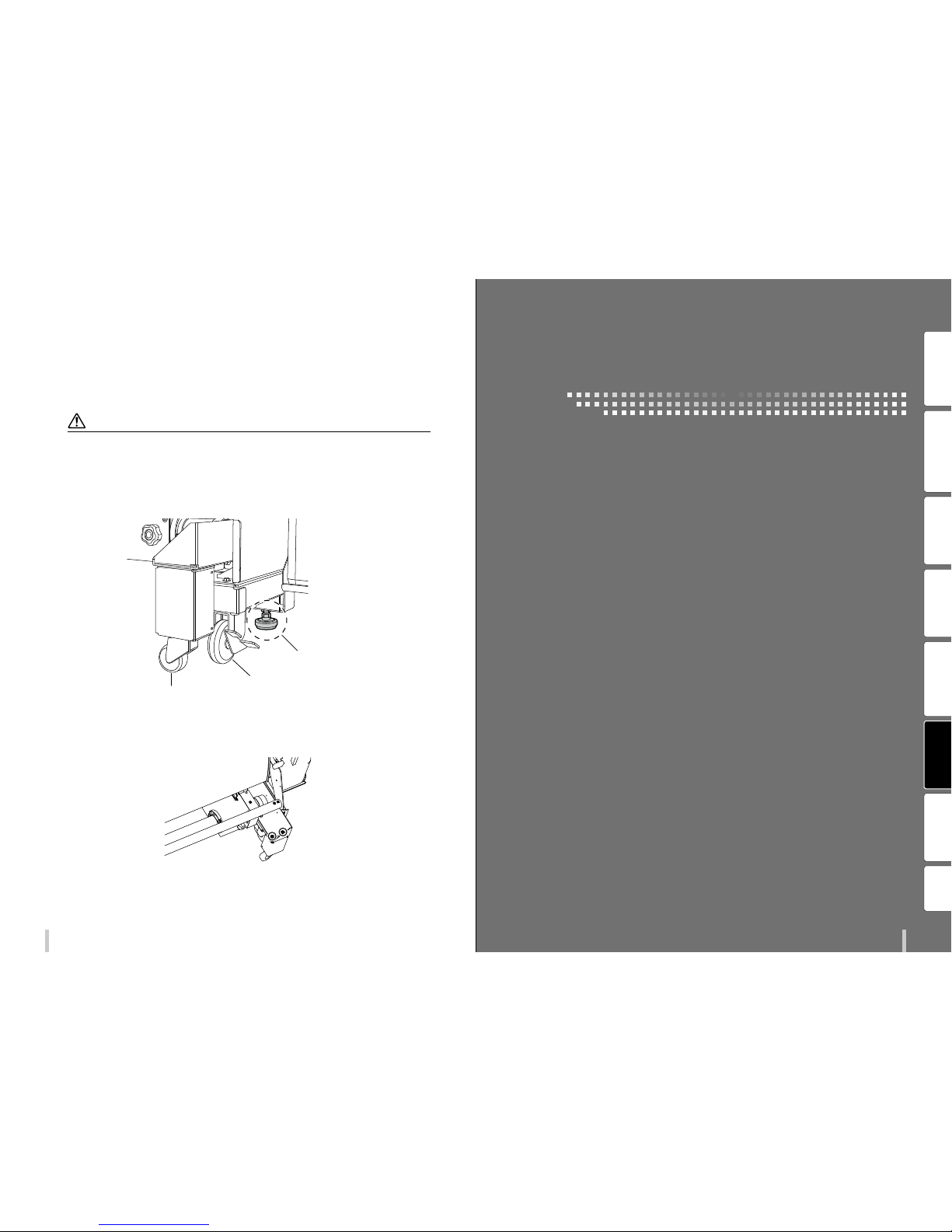
16716 6
Advanced operation s
Move the printer
If you wish to move the printer several meters on the same site, across a horizontal oor with no steps and no slopes,
see the following instructions.
For more dicult movement, contact your service representative.
CAUTI ON
Do not move the printer with a me dia roll attached. Othe rwise the heavy media may d amage the printer.
Raise a little the leveli ng feet (two on the front and two on t he rear) of the printer before movi ng the printer. Do not forget
to set these leveling fee t again after moving the printe r to secure it.
Move the printer carefull y so that the leveling feet do not hit any o bstructions.
Make sure that the TUR unit cas ters do not reach the oor when m oving the printer.
Adjustable leveling feet
TUR unit’s caster
Printer’s caster
If the casters touches t he oor, remove the screws shown circle d in the gure below. One caster is equ ipped at both the
right and left sides o f the TUR unit. Moving the printer w ithout removing them may damage t he TUR unit casters.
Before printing Loading the media Adjustment Maintenance
Advanced
operations
Troubleshooting
Menu tree Appendix
Troubleshooting
Page 85
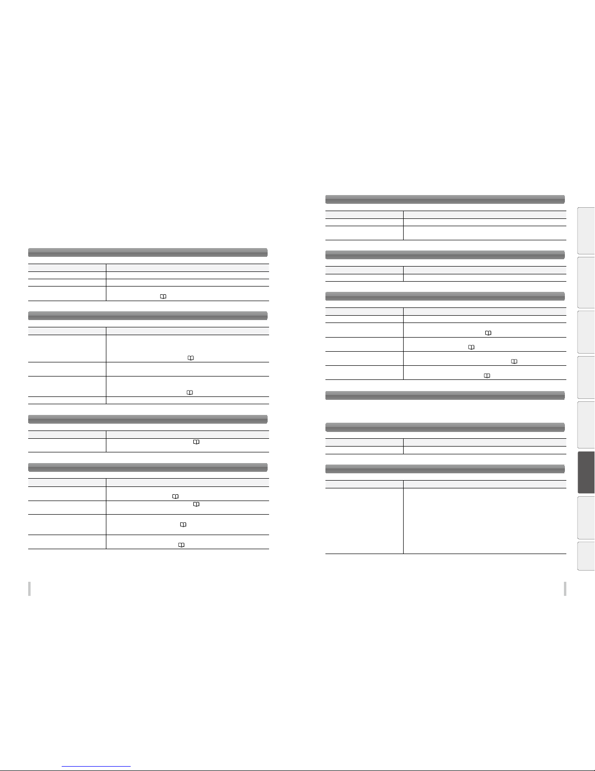
168 16 9
Troubleshooting Troubleshooting
Check the problem
Before deciding that there is a serious problem with the printer, check the following items.
Power does not turn on.
Items to be checked Corrective measures
Power cable connection Check that the power cable is correctly plugged into the power outlet.
Power supply to the outlet Supply power to the power outlet.
Power switch on/off Turn on the power switch.
See Turn the printer on on
page 29.
The paper guide is not heated even when the heater is turned on.
Items to be checked Corrective measures
Printer status The paper guide is heated during printing or when the heater is turned on with the
heater control menu. Make sure that the paper guide is heated by printing the nozzle
print pattern or set the heater to ON.
See Adjust the heaters temperatures on
pag e 157.
Host computer RIP software setting The heater temperature can also be set in the RIP sof tware on the host computer. Check
the host computer setting.
Heater control menu Turn on the heaters (afterheater/printheater/preheater) again, and then print the nozzle
print pattern or forcibly set the heater to ON to check that the paper guide is heated.
See Adjust the heaters temperatures on
pag e 157.
Power voltage Connect the printer to 200 V AC power.
The printer does not start or operate correctly.
Items to be checked Corrective measures
ERROR LED and message on the
operation panel
See When an error message is disp layed on
pa ge 173 .
The printer cannot print.
Items to be checked Corrective measures
USB cable connection Connec t the USB cable correctly.
See To connect the USB cable on
pag e 31.
ERROR LED and message on the
operation panel.
See When an error message is disp layed on
pa ge 173 .
Error LED off Print the nozzle adjustment pat tern.
See Print the nozzle print patte rn on
page 80. (Confirm that the RIP software
Test pat ter n is printed.)
Print head cleaning Clean the print heads.
See Performing normal cleaning on
page 79.
Although the printer is in the print mode, printing does not start with PREH EATI NG displayed on the operation panel.
Items to be checked Corrective measures
Room temperature Raise the room temperature. (Recommended temperature: 20 to 25ºC)
Effect of air flow If the air from an air conditioner or a fan is blowing against the paper guide, change the
air flow direction, the orientation of the printer, or the location of the printer.
The transmitted data is not printed.
Items to be checked Corrective measures
ONLINE LED (flashing?) Check the communication conditions to the host computer.
Media jams occur frequently.
Items to be checked Corrective measures
Media type Check wheth er the media type setting matches the type of media installed.
Media installation Install the media prop erly.
See Loading the media on the printer o n
page 36.
Obstructions in the carriage path or the
media path
Remove any obstructions.
See How to clear media jams on
pa ge 171.
Suction fan power If the suction fan power is not proper, reduce the power.
See Prevent the media from sticking an d wrinkling on
pag e 135.
Heater temperature set ting If the heater temperature is not optimally set, lower the heater temperature.
See Adjust the heaters temperatures on
pag e 157.
Print quality is poor.
See Solve print quality issues on page 184.
Printout are blank sheets.
Items to be checked Corrective measures
Print data Check the current print data to confirm that you sent blank sheet data.
Printing is slow. The carriage sometimes moves.
Items to be checked Corrective measures
USB connection speed When the data transmission speed is slow, the printer waits for the data with the print
heads capped.
Check the USB’s transmission speed. If the USB connection is full speed, the speed can
be improved by changing the conditions of the connection to the computer as follows,
so that the connection becomes high speed.
- Reconnect the USB cable.
- Connect the USB cable to the USB 2.0 port.
- Reinstall the driver.
- Change the USB cable to a cable supporting high speed transmissions.
- If a hub is used, change the hub to a model supporting high speed transmissions.
Before printing Loading the media Adjustment Maintenance
Advanced
operations
Troubleshooting
Menu tree Appendix
Page 86
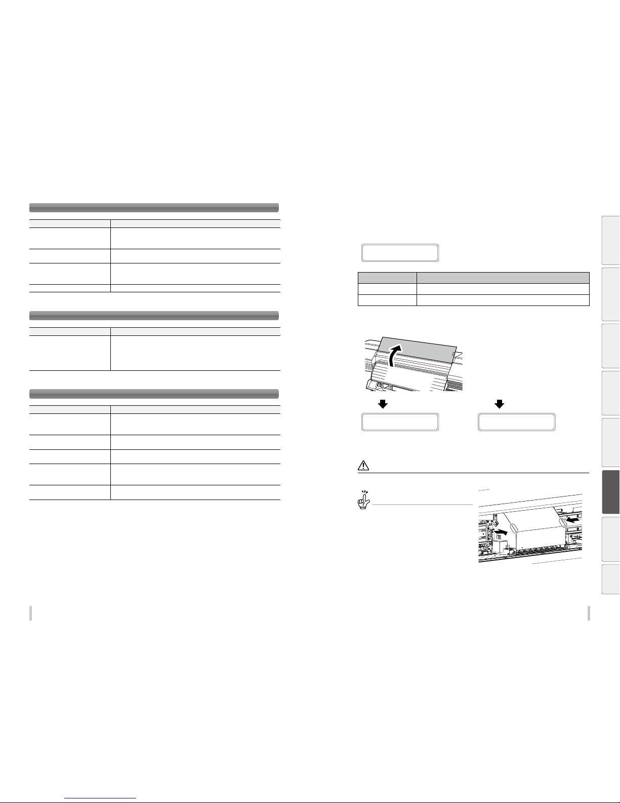
170 17 1
Troubleshooting Troubleshooting
Printing is slow. During print, print heads are capped frequently.
Items to be checked Corrective measures
High-temperature environment If the printer temperature is 40°C or more, the printer prints at a lower speed. Set the
ambient temperature to 20 to 25°C (recommended temperature), and leave the printer
for one hour or more before starting the print.
Computer specifications Remove any additional devices connected via USB.
Computer specifications Connect the printer to a computer satisfying the recommende d operational
environment for your RIP software. For the recommended operational environment,
contact the manufacturer of your RIP soft ware.
Computer other processing Terminate other software applications, for example, anti-virus soft ware.
You cannot understand the current operation panel display language.
Items to be checked Corrective measures
Language setting Start with the printer turned off. On the operation panel, press the MENU key and hold
it down. While holding the MENU key down, press the POWER switch and hold it down.
Continue to hold down both keys. Then the language selection menu appears on the
operation panel display. Highlight your preferred language with the Up and Down keys,
then press the OK key.
Clogged nozzles cannot be cleared.
Items to be checked Corrective measures
Damaged media edges If the media is damaged with s ome sections coming out from the edge guards, it may
contact the heads nozzle surfaces and cause nozzles to clog.
Cut any damaged sections with a pair of scissors or a cutter before installing the media.
Adhesive coming off the vinyl causing
the media to rise
Feed the media to beyond the risen area.
Media wrinkling and rising Set the suction fan level to HIGH.
Decrease the printh eater temperature.
Media adhering to the platen Set the suction fan level to LOW or OFF to make it advance again.
Setting media advance mode to BACK & FWD LOW may also prevent the media from
adhering to the platen.
Daily maintenance Check that the daily maintenance has been executed and that it is per formed
periodically.
How to clear media jams
1
MEDIA JAM ERROR 1
LIFT THE LEVER
The message to the left appears.
X: Media jam type Meaning
1: Media jam 1 A jam on the carriage is preventing the printer from operating correctly.
2: Media jam 2 A media not supported is used. The media cannot be detected correctly.
2
Lift the pressure roller lever and open the
fro nt cov er.
When you lift the lever
OPEN COVERS AND
REMOVE MEDIA
When you open the cover
LIFT THE LEVER A ND
REMOVE MEDIA
3
Clear the media jam, make sure that no obstruction is left in the carriage path and the media
feed path, and then close the front cover.
Note
In case of roll media, rewind som e of the media.
To manually move the carriage...
If the carriage must be move d manually, slide the
carriage by softly pre ssing locations indicated with
the arrows.
Before printing Loading the media Adjustment Maintenance
Advanced
operations
Troubleshooting
Menu tree Appendix
Page 87
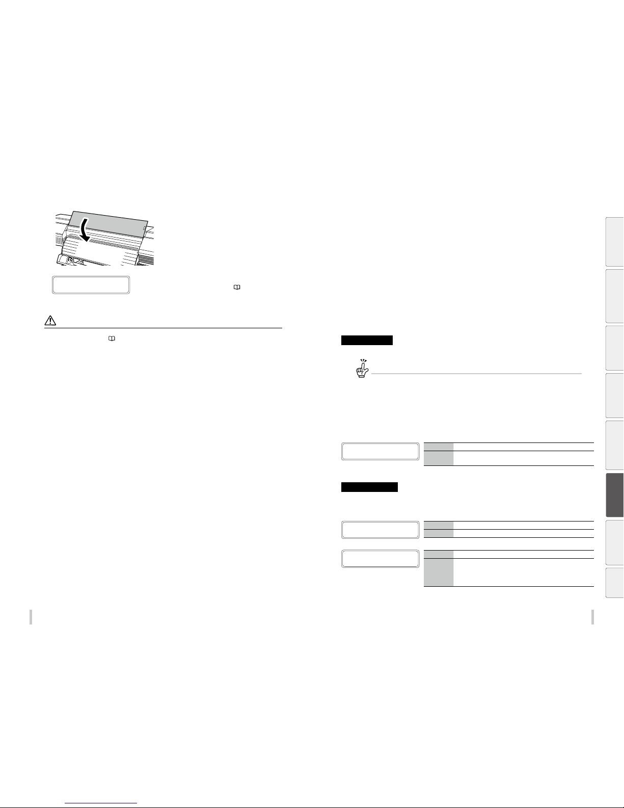
172 17 3
Troubleshooting Troubleshooting
4
Close the front cover.
The carriage moves to the home position.
5
CARRIAGE IS MOVIN G
PLEASE WAIT
Load the media on the printer again.
See To load media on the Printer on page 36.
Note
When the printer is jamme d with media, the print heads may con tact the media and cause pri nt misses. In such cases,
perform print head r ecovery. (
pag e 151
)
When an error message is displayed
When the ERROR LED lights up, check the message displayed on the operation panel.
Error messages shown below are classied into two groups.
Service call errors:
Errors that the operator (customer) cannot recover, such as hardware/software failures. Contact your service
representative.
Operator call errors:
Errors that the operator (customer) can recover.
To recover the error, follow the advice described here.
Service call errors
Restart the printer.
If a service call error o ccurs, restart the printer by turn ing it o and on as follows. Then the erro r may be recovered.
(1) Turn o the operation panel’s POWER switch and the main printer p ower switch on the rear of the printer and
the heater power switch.
(2) Remove the power cable front he power outlet , and then remove it from the power inlet at t he rear of the
printer.
(3) Hold the Printer for one minute or more.
(4) Connect each power cord above to its inl et, then connect the two cords to th e socket.
(5) Turn on all three switches above.
<System error>
SYSTEM ERROR nnnn
RESTART PRINTER
nnnn: Error code
Meaning
An unrecoverable error occurred.
Action
Contact your service representative, and inform them of the displayed
error code.
Operator call errors
The following errors can be recovered by the operator.
<Ink errors>
CLOSE INK BOX COVER
Meaning
The ink cover is open.
Action
You are advised to follow the message instructions.
SET CC INK CARTR IDGE
CC: Ink color
Meaning
An ink cartridge is not installed.
Action
You are advised to follow the message instructions.
If this message appears when a ink cartridge is installed for the specifie d
color, the ink cartridge installation may not be correct. Check that it is
installed properly.
Before printing Loading the media Adjustment Maintenance
Advanced
operations
Troubleshooting
Menu tree Appendix
Page 88
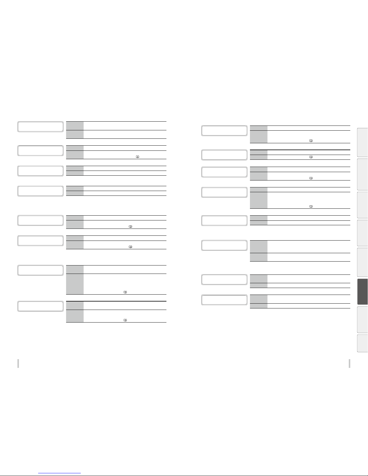
174 175
Troubleshooting Troubleshooting
CHECK CC CARTRIDGE
nn
nn: Ink error codeCC: Ink col or
Meaning
A problem occurred with an ink tray, or the ink cartridge was identified
as non genuine.
Action
You are advised to follow the message instructions.
Write down the displayed error code.
REPLACE CC CARTRIDGE
CC: Ink color
Meaning
The ink cartridge is empty.
Action
You are advised to follow the message instructions.
See Install and replace an ink car tridge on
page 163.
INK COLOR ERROR
CHECK CC CARTRIDGE
CC: Ink color
Meaning
The ink cartridge color is not correct.
Action
Install the correct ink cartridge.
CARTRIDGE T YPE ERROR
CHECK CC CARTRIDGE
CC: Ink color
Meaning
The ink cartridge type is not correc t.
Action
Install the correct ink cartridge.
<Waste ink bottle errors>
INSTALL
Meaning
No waste ink bottle is installed.
Action
You are advised to follow the message instructions.
See Replace the waste ink bottl e on
page 82.
REPLAC E
WASTE INK BOTTLE
Meaning
The waste ink bottle is full.
Action
You are advised to follow the message instructions.
See Replace the waste ink bottl e on
page 82.
<Media jam errors>
MEDIA JAM ERROR 1
LIFT THE LEVER
Meaning
An obstruction is left in the carriage path and the printer cannot drive
the carriage normally.
Action
Lift the pressure roller lever and open the front cover.
If the media jam (0) error occurs repeatedly although there is no
media jam or no obstruction in the carriage path, contact your ser vice
representative.
See How to clear media jams on
pa ge 171.
MEDIA JAM ERROR 2
LIFT THE LEVER
Meaning
A media not supported is used and the media cannot be detected
correctly.
Action
Lift the pressure roller lever and open the front cover.
Check also that the settings are correct.
See How to clear media jams on
pa ge 171.
<Media errors>
LIFT THE LEVER A ND
LOAD THE MEDIA
Meaning
No media is installed on the printer.
Action
When there is no media, install new media. If the flange is not attached
correctly, attach it correctly.
See Load media on the Printer on
page 36.
LOAD THE MEDIA
Meaning
The media cannot be detected.
Action
See Load media on the Printer on page 36.
LIFT THE LEVER
CHECK MEDIA
Meaning
The width of the installed media is not correct (longer than 64 inches).
Action
Load media of the specified size.
See Load media on the Printer on
page 36.
LIFT THE LEVER
ALIGN THE MEDIA
Meaning
The media has skewed.
Action
Reinstall the media correctly. Ink may have been discharged on the
platen depending on the skew level. In that case, completely remove
the ink from the platen.
See Load media on the Printer on
page 36.
MEDIA SKEW. CONTINUE
PRINT? OK/CANCEL
Meaning
Skewed media was detected during printing.
Action
Continue to print or stop printing.
<Print head error>
PH COOLING PROCESS
PLEASE WAIT
Meaning
The printer operation was suspended, as the print heads temperature
exceeded 40ºC. Th e print heads temperature is always monitored by
the printer to guarantee stable ink ejection.
Action
Secure an ambient temperature between 15 and 30ºC to prevent the
print heads temperature increase.
<Communication errors>
USB I/F ERROR
CHECK CONNECTION
Meaning
During the print data transfer, a USB connection failure or cable
disconnection was detected.
Action
Check the USB cable connection.
DATA TRANSFER ERROR
CHECK CONNECTION
Meaning
Though a timeout occurs during the print data transfer, its cause is not a
printer failure.
Action
Check the USB cable connection.
Before printing Loading the media Adjustment Maintenance
Advanced
operations
Troubleshooting
Menu tree Appendix
Page 89
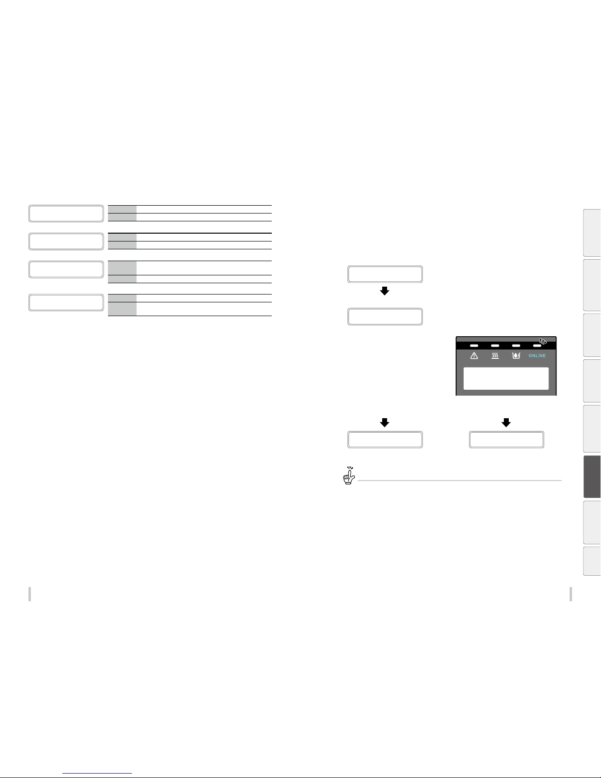
176 17 7
Troubleshooting Troubleshooting
<Other errors>
CLOSE COVER
Meaning
The front cover is open.
Action
You are advised to follow the message instructions.
PRIME INK SYSTEM
Meaning
Cleaning or printing was started before priming the ink system.
Action
Prime the ink system before starting cleaning or printing.
AMBIENT TEMP ERROR
ADJUST TEMPERATURE
Meaning
The ambient temperature is not within the printer’s operating
temperature range.
Action
Operate the printer within the operating temperature range (15 to 30ºC).
AN ERROR OCCURRED
PLEASE WAIT
Meaning
An error was detected during printing.
Action
Wait until the error message is displayed.
If no error messages are displayed after five minutes, restart the printer.
The media has skewed.
When the media skew check setting is on, the printer checks for skewed media after printing a certain length of
media. If the media has skewed more than a dened distance, the print pauses and a screen where you can select to
continue or stop the print is displayed.
PRINTING...
STANDARD ND BI
The printer checks for skewed media.
MEDIA SKEW. CONTINUE
PRINT? OK/CANCEL
Skewed media was detected.
- The ONLINE LED ashes slowly.
Continue printing with the OK key. Stop printing with the Cancel key.
PRINTING...
STANDARD ND BI
LIFT THE LEVER
ALIGN THE MEDIA
CANCEL is recommended.
If you select [OK] to continu e the print, the rest of the suspended p rinting job is started. However, the med ia may be
disengaged from the med ia edge guards, or the printer may be jamme d with media. When the printout is len gthy,
the skew may worsen, which may damage th e printer.
Before printing Loading the media Adjustment Maintenance
Advanced
operations
Troubleshooting
Menu tree Appendix
Page 90
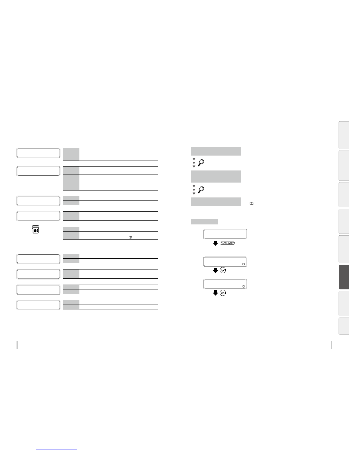
178 17 9
Troubleshooting Troubleshooting
Warning messages
After printing, occasionally you may see one of the following messages appear on the operation panel with the
ERROR LED ashing. They are warning messages. In such cases, follow the instructions in the Action rows.
SET INK CART RIDGE
AND SUPPLY INK
Meaning
After the subcartridge ink has been initially sent to the ink system, the
ink supply from the trays has not yet started.
Action
Set the ink cartridges to the ink box slots, and supply ink.
CHECK MEDIA
FOR WRINKLES
Meaning
The media is still installed on the printer and 24 hours has passed since
the last start maintenance operation.
Action
Perform one of the following actions.
(1) Lift the pressure roller lever.
(2) Press any key.
(3) Feed or back feed the media.
PERFORM
START MAINTENANCE
Meaning
24 hours has passed since the last start maintenance operation.
Action
Perform the start maintenance.
CHECK TUR UNIT
Meaning
A timeout occurs with a TUR unit process.
Action
Change the TUR unit switch configuration.
The Ink LED
blinks:
Meaning
Ink is running out.
Action
Prepare a new ink cartridge.
See Install and replace an ink car tridge on
page 163.
<Life-limited parts warnings>
REPLACE THE
SUPPLY PUMP
Meaning
The supply pump assembly needs to be replaced.
Action
You are recommended to ask your service representative to replace it.
REPLACE THE
WIPER BLADE
Meaning
The wiper blades need to be replaced.
Action
Replace the wiper blades.
REPLACE THE
WIPER CLEANING LIQUID
Meaning
The wiper cleaning liquid is running out.
Action
Supply wiper cleaning liquid.
REPLACE THE
WIPER SPONGE
Meaning
The wiper sponge needs to be replaced.
Action
Replace the wiper sponge.
Clear missing dots (nozzle clogging)
If the missing dots still appear after the daily maintenance and after setting NOZZLE MAP, perform the operation
belo w.
Strong cleaning
Perform the strong cleaning when missing dots still appear after the
normal cleaning.
Perform the NOZZLE PRINT
Fill the cap with ink
To clear the nozzle clogging, fill the cap with ink and moisten the print
head nozzle surface with ink. After this operation, leave the printer for 1 to
2 hours.
Perform the NOZZLE PRINT
Perform sheet mount cleaning
Clean the print heads surfaces with sheet mount cleaning.
See page 97.
Strong cleaning
1
PRINTER READY
01: PAPER / 1626mm
Press the PH.RECOVE RY key.
You can perform PH recovery in the following situations.
- When the printer is idle online
- When the printer is online
- During printing
- When the printer is in pause
2
PH RECOVERY
2
NORMAL
Press the Down key to select STRONG.
3
PH RECOVERY
2
STRONG
Press the OK key.
Before printing Loading the media Adjustment Maintenance
Advanced
operations
Troubleshooting
Menu tree Appendix
Page 91
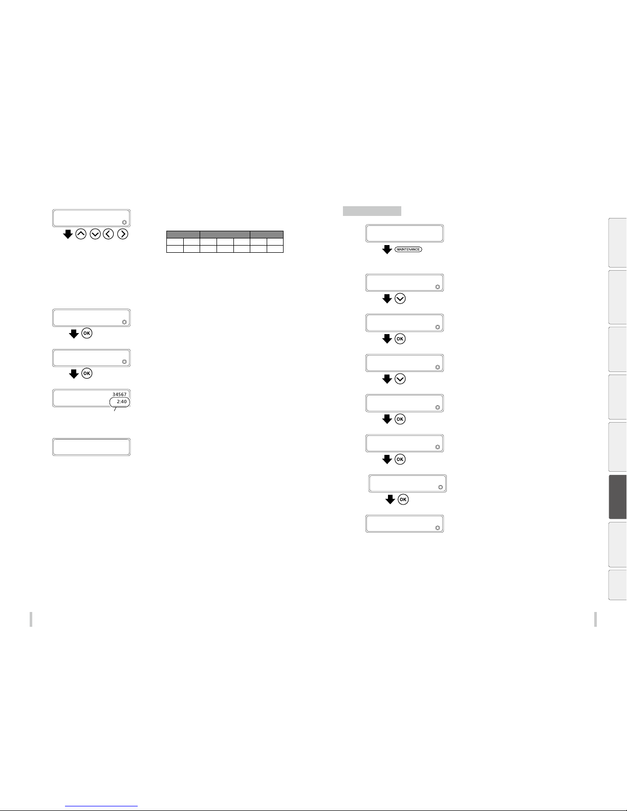
180 181
Troubleshooting Troubleshooting
4
>STRONG
2
PRINT HEAD:1234567
, ,
Select the print heads to clean.
The correspondence between the ink colors and the print
head numbers is shown in the table below.
Head group 1 Head group 2 Head group 3
Lc Lm C Y K M Gy
1 2 3 4 5 6 7
(1) Press the Le ft and Right keys to select the print head
number.
(2) Then press th Down and Up keys to display or hide the
number. Display it to clean the print head, or hide it not
to clean the print head.
5
>STRONG
2
PRINT HEAD: 34567
Press the OK key.
In the example to the left, the print heads C, Y, and K, and M
and Gy will be cleaned.
6
>STRONG 34567
BOTTLE IS EMPT Y?
Press the OK key.
Check visually that the waste ink bottle is not full.
PH RECOVERING 34567
REQUIRED TIME 2:40
The time is counted down every ten seconds.
Cleaning starts.
Print head cleaning takes several minutes.
When the cleaning starts, the required time is displayed and
the time is counted down every 10 seconds.
7
PRINTER READY
01: PAPER / 1626mm
The cleaning is complete.
The printers return to its state before cleaning.
- Online idle and online: Switches to online state
- Printing: Resume printing
- In pause: Stays in pause
Fill the cap with ink
1
PRINTER READY
01: PAPER / 1626mm
Press the MAINTENANCE key.
You can perform PH recovery in the following situations.
- When the printer is idle online
- When the printer is online
- During printing
- When the printer is in pause
2
MAINTENANCE
2
START MAINTENANCE
Press the Down key to select PH
MAINTENANCE.
3
MAINTENANCE
2
PH MAINTENANCE
Press the OK key.
4
>PH MAINTENANCE
2
CLEAN FOR STOR AGE
Press the Down key to select FILL CAP WITH
INK.
5
>PH MAINTENANCE
2
FILL CAP WITH I NK
Press the OK key.
6
>>FILL CAP WITH INK
BOTTLE IS EMPT Y?
Press the OK key.
7
>>FILL CAP WITH INK
EXECUTING
8
>PH MAINTENANCE
2
FILL CAP WITH I NK
Cap lling is complete.
Leave the printer for 1 to 2 hours.
After the printer has be left for 1 to 2 hours, perform the
normal cleaning.
Before printing Loading the media Adjustment Maintenance
Advanced
operations
Troubleshooting
Menu tree Appendix
Page 92
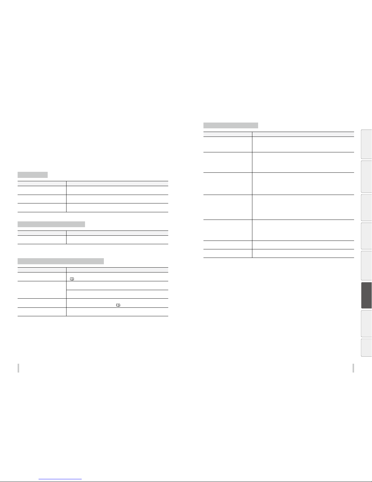
182 183
Troubleshooting Troubleshooting
Solve print quality issues
This section contains hints to enhance the print quality with the printer based on several symptoms.
Take appropriate actions according to the symptoms.
When several actions are described, they are arranged in order of eectiveness. Therefore, you are recommended
to take the actions starting from the top and conrm the eect on the improvement. (Note that all the described
actions are not always necessary to solve the problem.)
The print is pale.
Cause Solution
The density setting is not correct. Set density to HIGH DENSITY if high density printing is required, such as when using
backlit banner media.
The operating environment is outside
the specification of the Printer.
Raise the ambient temperature to 15ºC or more (20 to 25ºC recommended) to warm the
printer adequately.
Media is not selected properly. Check the media selection.
The printout is blurred or grains appear.
Cause Solution
The bidirectional and media advance
adjustment values are not correct.
(1) Perform bidirectional adjustment and media advance adjustment again.
(2) If automatic adjustment has been performed, perform manual adjustment.
Missing dots are found at the beginning of printing.
Cause Solution
Outside the operating temperature/
humidity range
Use the printer within the operating temperature/humidity range.
(
page 22)
Obstructions in the nozzle surfa ce Check the platen, the media edge guards, the capping unit, the wiper b lade, the
pressure roller, and the head guards, and remove any foreign matter.
Lint or paper fibers coming from a damaged media may touch the print heads, which
may cause missing dots. Replace the media with a media with no lint or paper fibers.
The media entered into contact with the
nozzle surfaces.
Perform normal cleaning.
If the problem persists, perform the ac tion
pa ge 17 9.
Cleaning did not finish normally. Perform the daily maintenance.
Clean the caps.
The media is curled or wrinkled.
Cause Solution
Outside the operating temperature/
humidity range
(1) Use the printer within the operating temperature/humidit y range.
* Note that some media may wrinkles eve n within the operating temperature and
humidity range.
(2) Use proven media.
The media storage conditions are not the
same as the printer operating conditions.
The difference between the media storage conditions and the pr inter operating
conditions may cause the media to curl or wrinkle. To prevent this, after carrying the
media from storage to the operation area, leave the media for while time in the new
environment before printing.
* The time depends on the media type and the s torage conditions.
The media was not installed properly. Check that the media was installed properly in the conditions below.
- The installed media is insta lled parallel to the printer.
- The operation panel shows th e media type correctly.
- The media winding mode is opti mal for the installed media.
- Check that the leading of the m edia output from the printer is installed straight to th e
TUR unit paper tube.
The media wrinkled because of the
heater temperatures.
(1) If the me dia wrinkles while the printer is warmed by the heaters, install the media
only after the printer is warmed up by the heaters.
(2) Change the heater temperature. Increase or decrease all three heaters by 5°C.*
1
(3) Use proven media.
(4) If the m edia is still wrinkle, feed the media until you reach a portion without wrinkles.
(5) If the media wrinkles between each print job, change the media advance mo de.
The media is curled. (1) Do not use media curled in the vertical direction direction (vertic al to the media).
(2) Do not use me dia curled in the horizontal direction (from the right edge to left
edge). The is so curled that the media edge guards and the suction fan cannot flat
the media.
(3) Use proven media.
Set the suction fan parameter of the
preset to LOW.
Set the suction fan parameter of the preset to a stronger setting.
Wrinkles caused by media advance (1) Remove the media and install it again.
(2) Use proven media.
*1 When the heaters temperatur es are changed, adjust the media adva nce adjustment value again.
Before printing Loading the media Adjustment Maintenance
Advanced
operations
Troubleshooting
Menu tree Appendix
Page 93
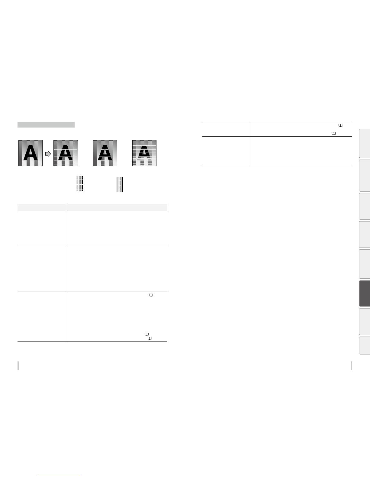
184 185
Troubleshooting Troubleshooting
White stripes appear on the print.
Basic image [Symptom A] [Symptom B] [Symptom C]
[Cause]
Media advance compensation is
not proper.
[Check]
White stripes appear in all
colors when a color stripe
bar is printed.
[Check]
White stripes appear in some
colors when a color stripe bar
is printed.
[Cause]
The ink does not match well with
the media.
[Cause]
The print head nozzles are
clogged.
Cause Solution
[Symptom A]
Media feed is not adjusted properly.
Adjust the media advance adjustment value.
* T he media advance adjustment value dier s depending on the winding mode, loose o r
tension.
- Be sure to adjust the media advance adjus tment value again after changing the w inding
mode (loose or tension).
- Be sure to adjust the media advance adju stment value again after changin g the pressure
roller lever position.
- Be sure to adjust the media advance adjustment valu e again after changing the suction
fan setting of the media p reset.
[Symptom A]
The media advance accuracy is poor, or
is not stable.
(1) Check that the me dia was installed properly in the conditions below.
- The installed media is insta lled parallel to the printer.
- The operation panel shows th e media type correctly.
- The media winding mode is opti mal for the installed media.
- I f the media is curled or wrinkled, see the descr iption on the problem, The media is
curled or wrinkled.
(2) Adjust the pressure on the media with the pressure roller lever. *1
(3) Change the print mode to be slower. *
1 *2
Check that the media is correctly stretched between the paper roll and the pressure
rolle r.
* If the media is loose when pe rforming the media advance adjustm ent, the value will be
incorrect.
[Symptom B]
Print head nozzles are clogged.
(1) Perfor m a nozzle print, and set nozzle map for the clogged nozzles. (
page
80)
(2) Check for obs tructions such as media lint or ink clot in the nozzle scanning path
including the platen surface, and remove them.
(3) If the me dia is curled or wrinkled, solve the problem by referring to the description
on the problem, The media is curled or wrinkled.
(4) Perfor m the daily maintenance.
* Do not forget to clean the head guard and edge guards.
* Be sure to perform the print head cleaning.
(5) Perfor m SET CAP FOR CLNG.
(6) Clean the print heads surfa ces with print sheet mount cleaning (
page 97 ).
- Printing with a color stripe bar is effective to prevent missing dots. (
pag e 126)
[Symptom C]
Print head nozzles inclination
(1) Print a nozzle pr int pattern, and set nozzle map for the inclined nozzles. (
page
80)
(2) Printing with a color stripe b ar is effective to prevent missing dots. (
pag e 126)
[Symptom C]
The ink does not match the media.
(Media with low dot spread rate)
(1) Decrease the temperature of all three heaters by 5°C. *
1
* Before st arting the print, ensure that the heater temperatures have be en decreased to
the target temperature.
* With some media, the increasing the heater temper atures may be eective.
(2) Change the print mode to be slower. *1 *2
(3) Use proven media.
(4) Print in high density.
*1 Adjust the media advance adjustm ent value again.
*2 Note that the print speed die rs depending on the mode sele cted.
Before printing Loading the media Adjustment Maintenance
Advanced
operations
Troubleshooting
Menu tree Appendix
Page 94
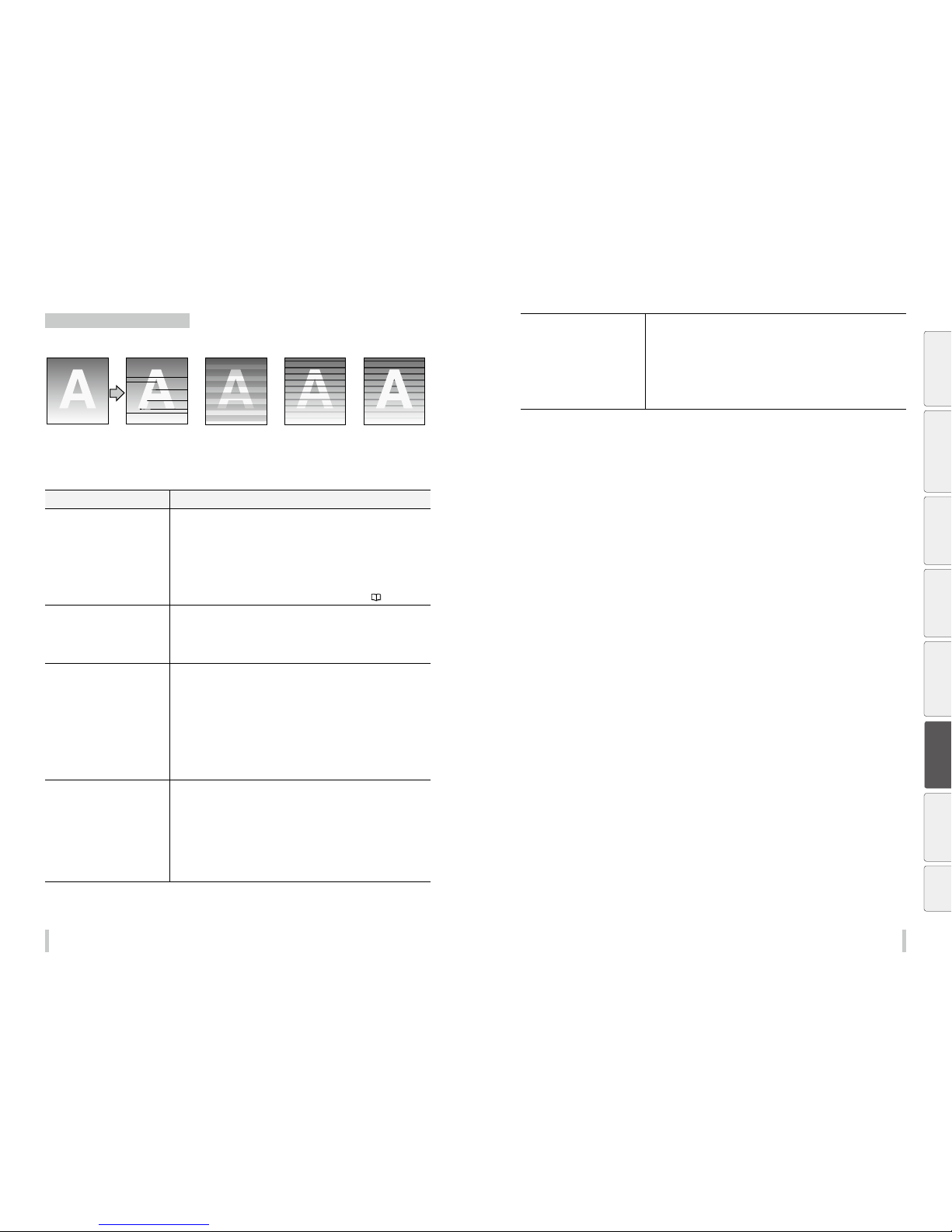
186 187
Troubleshooting Troubleshooting
Black stripes appear on the print.
Basic image [Symptom A] [Symptom B] [Symptom C] [Symptom D]
[Cause]
The print head periphery
is smeared.
[Cause]
At bidirectional printing,
the ejected ink’s color
order in rightward print
is dierent from in
leftward print.
[Cause]
The media advance
compensation is not
proper.
* Black stripes appear over the print. * Black stripes appear partly on the
print.
[Cause]
The ink dries too slowly.
Cause Solution
[Symptom A]
The print heads periphery is smeared.
(1) Check for obs tructions such as media lint or ink clot in the nozzle scanning path
including the platen surface, and remove them.
(2) If the me dia is curled or wrinkled, solve the problem by referring to the description
on the problem, The media is curled or wrinkled.
(3) Perfor m the daily maintenance.
* Do not forget to clean the head guard and edge guards.
* Be sure to perform the print head cleaning.
(4) Perfor m SET CAP FOR CLNG.
(5) Clean the print heads surfa ces with print sheet mount cleaning (
page 97 ).
[Symptom B]
During bidirectional printing, the order
of ejected ink colors in the rightward
direction differs form that in the left ward
dircetion.
(1) Change the print mode to be slower. *
1 *2
*
3
(2) Print in unidirectional mod e. *2
(3) Use proven media.
[Symptom C]
The media advance adjustment value is
incorrect.
(1) Adjust the media advan ce adjustment value.
(2) Check that the media is correctly stretched between the paper roll and the pressure
rolle r.
* If the me dia is loose when performing the medi a advance adjustment, the value will be
incorrect.
- The adjustment value die rs depending on the winding mo de, tension or loose.
- Be sure to adjust the media advance adjustm ent value again after changing the suct ion fan
setting.
- Be sure to adjust the media advance adjustment value again af ter changing the pressure
roller lever position.
- If the ionizer is set to ON , set it OFF.
- If automatic adjustme nt has been performed , perform manual adjustme nt.
[Symptom C]
The media advance accuracy is poor, or
is not stable.
(1) Check that the media was installed properly in the conditions bel ow.
- The installed media is insta lled parallel to the printer.
- The operation panel shows th e media type correctly.
- The media winding mode is opti mal for the installed media.
- I f the media is curled or wrinkled, see the descr iption on the problem, The media is
curled or wrinkled.
(2) Adjust the pressure on the media with the pressure roller lever. *1
(3) Change the print mode to be slower. *
1 *2
(4) Change the suction fan power. *
1
(5) If the ionizer is set to ON, set it OFF.
[Symptom D]
The ink dries too slowly.
(Mottling or bleeding occurs.)
(1) Increase the temperature of all three heaters by 5°C. *
1
* Before st arting the print, ensure that the heater temperatures have be en decreased to
the target temperature.
(2) Change to a more suitable print mode, or set the car riage speed to SLOW.
*
1 *2
*
3
(3) Print in unidirectional mod e. *2
(4) Use proven media.
(5) With the R IP software, apply the profile with a low ink amount to be ejected.
* Note that the hue may change if the ejected ink amount decr eases.
*1 Adjust the media advance adjustm ent value again.
*2 Note that the print speed die rs depending on the mode sele cted.
*3 Be sure to adjust the bidirect ional adjustment value again afte r changing the carriage speed.
Before printing Loading the media Adjustment Maintenance
Advanced
operations
Troubleshooting
Menu tree Appendix
Page 95
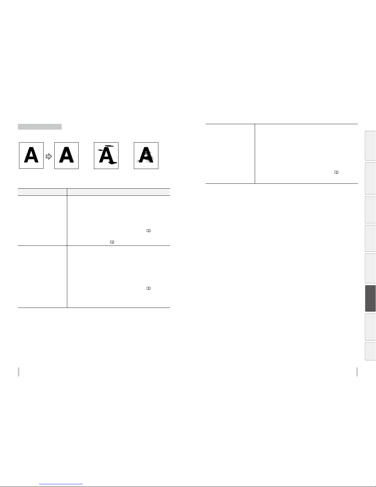
188 189
Troubleshooting Troubleshooting
The printout is not clean.
[Cause]
The ink is improperly sprayed
from the print head.
[Cause]
The ink is drooling.
[Cause]
The print head is scratched by
media.
Basic image [Symptom A] [Symptom B] [Symptom C]
Cause Solution
[Symptom A]
The ink is improperly ejected from the
print heads.
(1) Use the printer within the operating temperature/humidit y range.
(2) Perfor m the daily maintenance.
* Be sure to clean the he ad guard, edge guards, carriage bottom sur face, and the right
and left sides of the top of th e print heads.
(3) Perfor m print head cleaning (STRONG).
(4) Change to a more suitable print mode, or set the car riage speed to SLOW.
*
1 *2
*
3
(5) Perfor m SET CAP FOR CLNG.
(6) Clean the print heads surfa ces with print sheet mount cleaning (
page 97 ).
(7) If the print heads height set ting is set to high, set it to normal. *
4
* If problems occur w ith the media used when the print heads height set ting is set to
normal, set it to another opti on. (
pag e 132)
[Symptom B]
The ink dribbles.
(1) Use the printer within the operating temperature/humidit y range.
(2) Check for obs tructions such as media lint or ink clot in the nozzle scanning path
including the platen surface, and remove them.
(3) If the me dia is curled or wrinkled, solve the problem by referring to the description
on the problem, The media is curled or wrinkled.
(4) Perfor m the daily maintenance.
* Do not forget to clean the head guard and edge guards.
* Be sure to perform print head cleaning.
* Be sure to clean the caps.
(5) Perfor m SET CAP FOR CLNG.
(6) Clean the print heads surfa ces with print sheet mount cleaning (
page 97 ).
(7) With me dia that easily creates static electricity, the static electricity may cause the
ink to dribble. With such media, set the ionizer to ON. *1
(8) With so me banner media, light media edges may touches the print heads, which
may cause the ink to dribble.
[Symptom C]
The print heads are scratched by the
media.
(1) Check that the me dia was installed properly in the conditions below.
- The installed media is insta lled parallel to the printer.
- The operation panel shows th e media type correctly.
- The media winding mode is opti mal for the installed media.
- I f the media is curled or wrinkled, see the descr iption on the problem, The media is
curled or wrinkled.
(2) Check for obs tructions such as media lint or ink clot in the nozzle scanning path
including the platen surface, and remove them.
(3) Perfor m the daily maintenance.
* Do not forget to clean the head guard and edge guards.
* Be sure to perform print head cleaning.
(4) Perfor m SET CAP FOR CLNG.
(5) Clean the print heads surfa ces with print sheet mount cleaning (
page 97 ).
(6) Set the suc tion fan parameter of the preset to a stronger setting. *
1
(7) If the ionizer is set to ON, set it OFF.
*1 Adjust the media advance adjustm ent value again.
*2 Note that the print speed die rs depending on the mode sele cted.
*3 Be sure to adjust the bidirect ional adjustment value again afte r changing the carriage speed.
*4 Adjust the bidirectional print p ositions.
Before printing Loading the media Adjustment Maintenance
Advanced
operations
Troubleshooting
Menu tree Appendix
Page 96
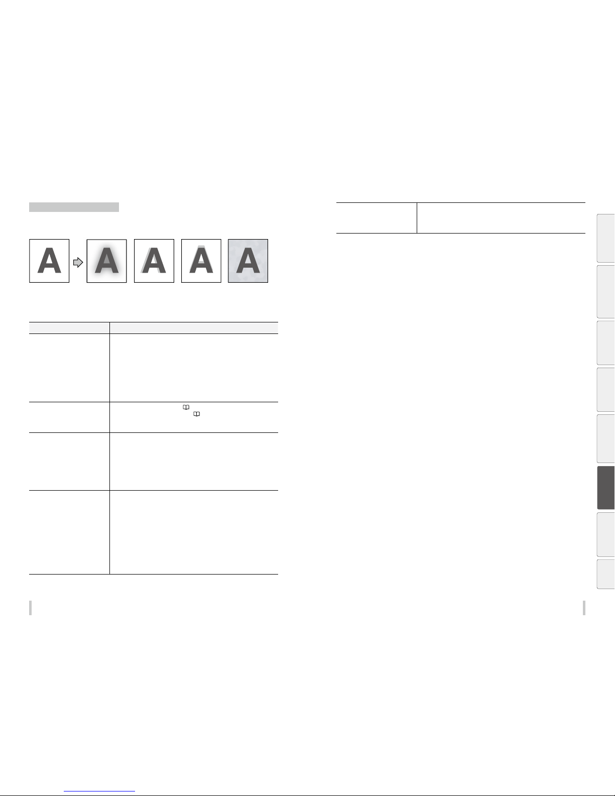
19 0 191
Troubleshooting Troubleshooting
Contours of objects are blurred.
[Symptom A]Basic image [Symptom B] [Symptom C] [Symptom D]
[Cause]
The ink dries too slowly.
The ink is ejected
excessively.
[Cause]
The print head position
is misaligned.
The bidirectional print
position is misaligned.
[Cause]
The media advance
compensation is not
proper.
[Cause]
The static electricity
accumulated on the
media
Cause Solution
[Symptom A]
The ink dries too slowly.
The ink is ejected excessively.
(1) Decrease the temperature of all three heaters by 5°C. *
1
* Before st arting the print, ensure that the heater temperatures have be en decreased to
the target temperature.
(2) Change to a more suitable print mode, or set the car riage speed to SLOW.
*
1 *2 *3
(3) Print in unidirectional mod e. *
2
(4) If printing in high density, print in normal density.
(5) Use proven media.
(6) With the R IP software, apply the profile with a low ink amount to be ejected.
* Note that the hue may change if the ejected ink amount dec reases.
[Symptom B]
The print heads positions are misaligned.
The bidirectional print position is
misaligned.
(1) Adjust the print heads positions. (
page 59)
(2) Adjust the bidirec tional print position. (
page 66)
(3) If bidirec tional adjustment has been performed automatically, perform it again
manually.
[Symptom C]
The media advance adjustment value is
incorrect.
Correct the media advance adjustment value. If media advance adjustment has been
performed automatically, perform it again manually.
- The adjustment value diers d epending on the winding mode, tensi on or loose.
- Be sure to adjust the media advance adjustment valu e again after changing the suction
fan power.
- Be sure to adjust the media advance adju stment value again after changin g the pressure
roller lever position.
- If the ionizer is set to ON, set it OFF.
- If automatic adjustment has been p erformed, perfo rm manual adjustment.
[Symptom C]
The media advance accuracy is poor, or
is not stable.
(1) Check that the me dia was installed properly in the conditions below.
- The installed media is insta lled parallel to the printer.
- The operation panel shows th e media type correctly.
- The media winding mode is opti mal for the installed media.
- I f the media is curled or wrinkled, see the descr iption on the problem, The media is
curled or wrinkled.
(2) Adjust the pressure on the media with the pressure roller lever. *
1
(3) Change to a more suitable print mode, or set the car riage speed to SLOW.
*
1 *2 *3
(4) Check that the media is correctly stretched bet ween the paper roll and the pressure roller.
* If the media is loose when pe rforming the media advance adjustm ent, the value will be
incorrect.
(5) If the ionizer is set to ON, set it OFF.
[Symptom D]
Print defect caused by media static electricity
/ Ink sprayed over white portions of the
media.
(1) Set the ionizer to ON. *
4
(2) Change to a more suitable print mode, or set the car riage speed to SLOW.
*
1 *2 *3
(3) Use proven media.
*1 Adjust the media advance adjustm ent value again.
*2 Note that the print speed die rs depending on the mode sele cted.
*3 Be sure to adjust the bidirect ional adjustment value again afte r changing the carriage speed.
*4 Set the ionizer to OFF with media where n o print defects caused by st atic electricity occur.
Before printing Loading the media Adjustment Maintenance
Advanced
operations
Troubleshooting
Menu tree Appendix
Page 97
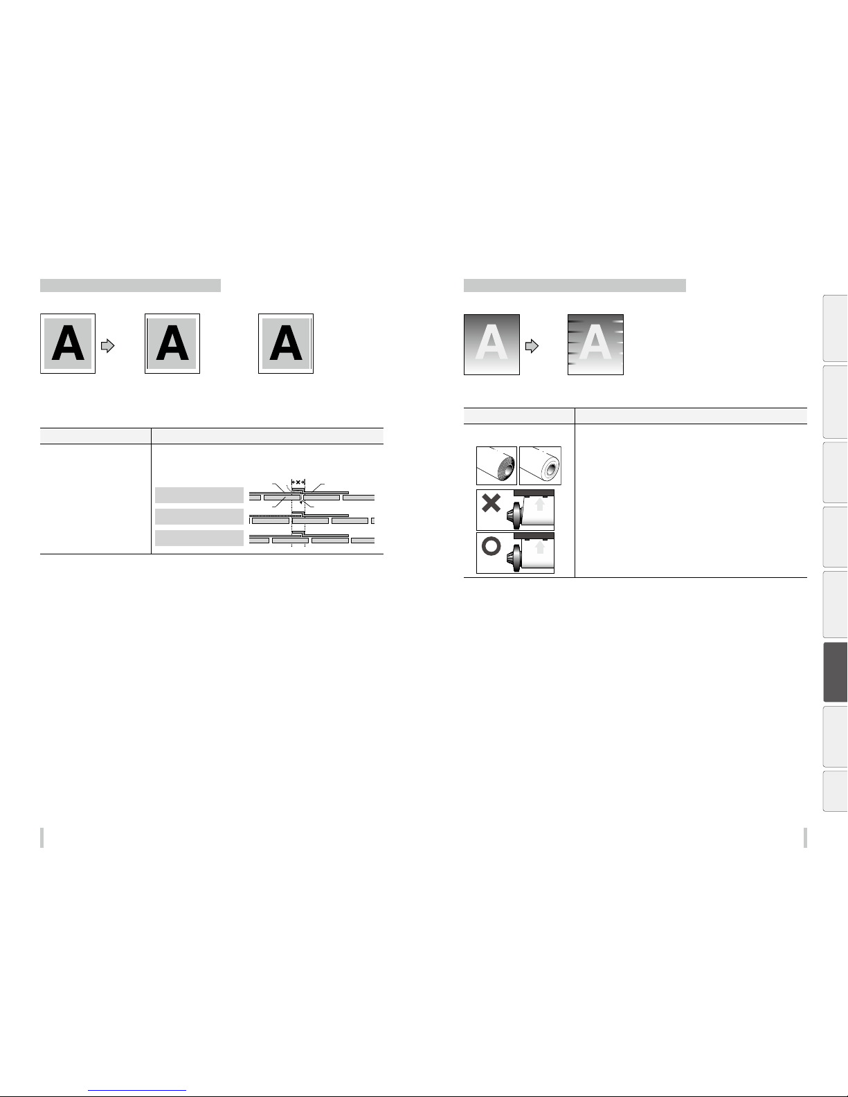
192 193
Troubleshooting Troubleshooting
Vertical banding appears at the printout edges.
Basic image [Symptom A] [Symptom B]
[Cause]
On the platen, the contacting point of the
media left edge and the media edge guard
is near the platen’s vacuum hole.
[Cause]
On the platen, the contacting point of the
media right edge and the media edge guard
is near the platen’s vacuum hole.
Cause Solution
[Symptom A] [Symptom B]
When, on the platen, the contacting
point between a media edge and the
media edge guard is near a platen’s
vacuum hole, the printer may suck the
ejected ink partially between the media
and the media edge guard. As a result,
vertical banding may appear.
Shift the media so that the contacting point between the me dia edge and the media
edge guard on the platen does not come close to the vacuum hole.
Platen
Media edge guard
Media
Vacuum hole
An example of media position when a
vertical banding appear
Example (1) of shifting the media
position when a vertical banding appear
Example (2) of shifting the media position
when a vertical banding appear
* Avoid the platen’s vacuum hole for this area.
Dierent bands appear on the printout right and left sides.
Basic image
[Cause]
The media is skewed.
Cause Solution
A skewed media is fed.
Example of skew
Example of dent
Media
Media
Example of skew
Example of dent
Media
Media
Printer
Printer
Bad
example
Good
example
(1) Check that the me dia condition is good. If the media roll is damaged or wound in
the shape of a cone, replace the roll with a good one.
(2) Check that the me dia was installed properly in the conditions below.
- The installed media is insta lled parallel to the printer.
- The operation panel shows th e media type correctly.
- The media winding mode is opti mal for the installed media.
- I f the media is curled or wrinkled, see the descr iption on the problem, The media is
curled or wrinkled.
(3) Check that the take up -side media shows no irregular winding. If an irregular
winding is found, reinstall the media on the printer and onto the take-up reel unit.
(4) Adjust the pressure on the media with the pressure roller lever. *1
(5) Use proven media.
(6) Check that the me dia holders on the supply side securely and firmly support the
media.
(7) Check that the me dia holders on the supply side are secured to the shaft with the
screws.
*1 Adjust the media advance adjustm ent value again.
Before printing Loading the media Adjustment Maintenance
Advanced
operations
Troubleshooting
Menu tree Appendix
Page 98

195194
Troubleshooting
Before printing Loading the media Adjustment Maintenance
Advanced
operations
Troubleshooting
Menu tree
Appendix
Menu tree
Page 99
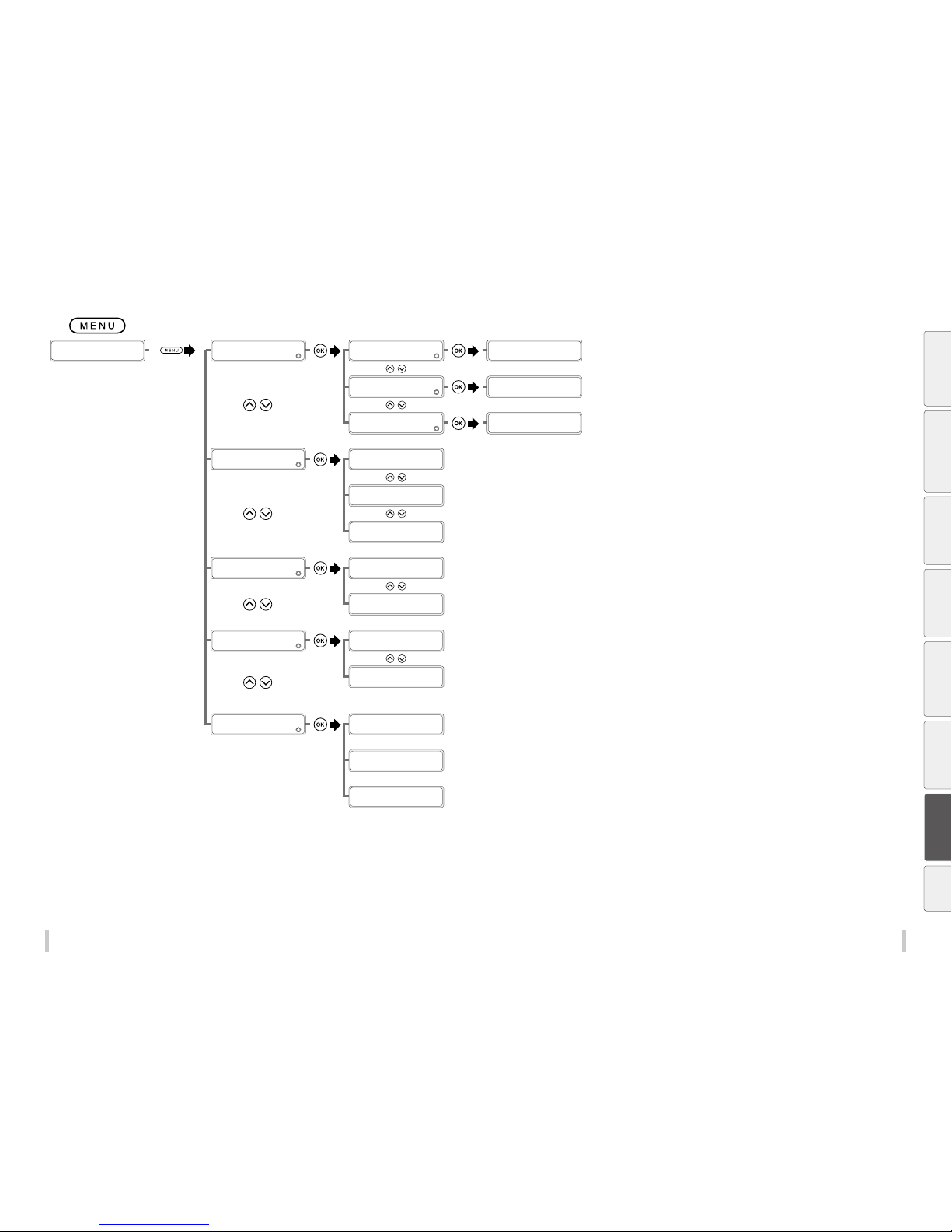
196 197
Menu tree Menu tree
Before printing Loading the media Adjustment Maintenance
Advanced
operations
Troubleshooting
Menu tree
Appendix
PRINTING...
STANDARD ND BI
MENU
2
INK INFORMATION
>INK INFORMATION
2
REMAINING INK
>>REMAINING INK
2
CC XXX%
CC: Ink color
XXX%: Remaining ink
(printing)
>INK INFORMATION
2
INK MFG DATE
>>INK MFG DATE
2
CC YYYY/MM/DD
CC: Ink color
YYYY/MM/DD: Manufacturing date
>INK INFORMATION
2
INK WASTE PERCEN T
>>INK WASTE PERCEN T
2
XXX%
XXX%: Waste ink quantity
MENU
2
CURRENT PRIN T JOB
>CURRENT PRI NT JOB
2
PROGRESS XXX%
XXX%: Print progress p ercentage
>CURRENT PRI NT JOB
2
REQUIRED TIME HH:MM
HH:MM: Estimated comp letion time (24-hou r display)
>CURRENT PRI NT JOB
2
PRODUCTIV ITY XX.X
XX.X: Produc tivity of the curre nt printing operati on (by unit of
length)
MENU
2
REMAINING MEDIA
>REMAINING MEDIA
XX: NNNNNNN YYYm
XX: Preset number
NNNNNN: Media name
YYY: Remaining length (in millimeters)
>REMAINING MEDIA
XX: NNNNNNN YYYYft
XX: Preset number
NNNNNN: Media name
YYY: Remaining len gth (in inches)
MENU
2
TOTAL PRINT LENGTH
>TOTAL PRINT LENGTH
YYYYYm
YYYYY: Sc anning distance (in mill imeters)
>TOTAL PRINT LENGTH
YYYYYYft
YYYYY: Sc anning distance (in inc hes)
<Warning examples>
MENU
2
WARNING INFO
CHECK TUR UNIT
PERFORM
START MAINTENANCE
<No warnings>
NO WARNING
Page 100
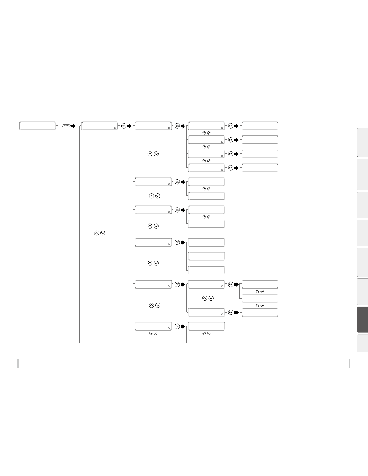
198 19 9
Menu tree Menu tree
A B C
Before printing Loading the media Adjustment Maintenance
Advanced
operations
Troubleshooting
Menu tree
Appendix
PRINTER REA DY
01: PAPER / 1626mm
MENU
2
INFORMATION
>INFORMATION
2
INK INFORMATION
>>INK INFORMATION
2
REMAINING INK
>>>REMAINING INK
2
CC XXX%
CC: Ink color
XXX%: Remaining ink
(not printing)
>>INK INFORMATION
2
INK MFG DATE
>>>INK MFG DATE
2
CC YYYY/MM/DD
CC: Ink color
YYYY/MM/DD: Manufacturing date
>>INK INFORMATION
2
INK WASTE PERCEN T
>>>INK WASTE PERCENT
2
XXX%
XXX%: Waste ink quantity
>>INK INFORMATION
2
TOTAL USED INK
>>>TOTAL USED INK
2
CC 000000000
CC: Ink color
>INFORMATION
2
REMAINING MEDIA
>REMAINING MEDIA
XX: NNNNNNN YYYm
XX: Preset number
NNNNNN: Media name
YYY: Remaining length (in millimeters)
>REMAINING MEDIA
XX: NNNNNNN YYYYft
XX: Preset number
NNNNNN: Media name
YYY: Remaining len gth (in inches)
>INFORMATION
2
TOTAL PRINT LENGTH
>>TOTAL PRINT LENGTH
YYYYYm
YYYYY: Sc anning distance (in mill imeters)
>>TOTAL PRINT LENGTH
YYYYYYft
YYYYY: Sc anning distance (in inc hes)
<Warning examples>
>INFORMATION
2
WARNING INFO
CHECK MEDIA
FOR WRINKLE S
PERFORM
START MAINTENANCE
<No warnings>
NO WARNING
>INFORMATION
2
MAINTENANCE INFO
>>MAINTENANCE INFO
2
MAINTENANCE STATUS
>>>MAINTENANCE STATUS
2
TOTAL SCORE: XXX
XXX points: Mainten ance execution score
>>>MAINTENANCE STATUS
2
RECENT SCORE: X XX
XXX points: Mainten ance execution score
>>MAINTENANCE INFO
2
CLEANING DATE&TIME
>>>CLEANING DATE&TIME
2
MM/DD hh:mm
MM/DD hh:mm: Cleaning e xecution date
>INFORMATION
2
VERSION INF O
>>VERSION INFO
2
BOOT X.X X
Displays boot version.
 Loading...