

Page 1
User's Guide
U00122912802
Seiko I Infotech Inc.
Read this User’s Guide before operating the
printer.
Keep this manual for future reference.
Solvent Ink Color Inkjet Printer
IP-5620/5520
Page 2

IP-5620/IP-5520 Solvent Ink Color Inkjet Printer User's Guide
Documents Number U00122912802, Third Edition, September 2011
Copyright © 2011 by Seiko I Infotech Inc.
All rights reserved
The contents of this manual may be changed without prior notice.
Seiko I Infotech Inc. reserves the right to make changes without notice to the specifications
and materials contained herein and shall not be responsible for any damages (including
consequential) caused by reliance on the materials presented, including but not limited to
typographical, arithmetic, or listing errors.
Please address any questions, comments, and suggestions to :
Seiko Instruments GmbH, French branch
20 rue Jean Rostand, 91400 Orsay France
Phone: +33-1-60-19-35-41
Fax: +33-1-60-19-35-17
Seiko Instruments USA Inc., Infotech Division
2067 Wineridge Place, Suite C, Escondido,
CA 92029, USA
Phone: +1-760-781-5200
Fax: +1-760-745-1195
Seiko I Infotech Inc.
8 Nakase 1-chome, Mihama-ku, Chiba-shi, Chiba 261-8507, Japan
Phone : +81 43 211 1363
Fax : +81 43 211 8709
This guide acknowledges the following trademarks :
is a trademark of Seiko Instruments Inc.
All other trademarks are the properties of their respective companies.
This equipment has been tested and found to comply with the limits for a Class A digital device,
pursuant to Part 15 of the FCC Rules. These limits are designed to provide reasonable protection
against harmful interference when the equipment is operated in a commercial environment.
This equipment generates, uses, and can radiate radio frequency energy and, if not installed
and used in accordance with the instruction manual, may cause harmful interference to radio
communications. Operation of this equipment in a residential area is likely to cause harmful
interference in which case the user will be required to correct the interference at his own
expense.
Page 3

The CE mark, that shows that the products sold in the EU are conformed to the requirements of
EC directive, is statutorily obliged to be affixed to the products.
In each directive, the scope of directive to be applied to equipment is explicitly defined. Our
company’s product IP-5620/IP-5520 conforms the EMC directive (2004/108/EC)) and low voltage
directive (2006/95/EC).
Inquiry of CE mark:
Seiko Instruments GmbH, French branch
20 rue Jean Rostand, 91400 Orsay France
Phone: +33-1-60-19-35-41
Fax: +33-1-60-19-35-17
Seiko Instruments USA Inc., Infotech Division
2067 Wineridge Place, Suite C, Escondido,
CA 92029, USA
Phone: +1-760-781-5200
Fax: +1-760-745-1195
Seiko I Infotech Inc.
8 Nakase 1-chome, Mihama-ku, Chiba-shi, Chiba 261-8507, Japan
Phone : +81 43 211 1363
Fax : +81 43 211 8709
Page 4

Page 5

Thank you very much for purchasing the IP-5620/IP-5520 Color Inkjet Printer (hereafter simply called the printer.)
IP-5620 supports media up to 64 inch width and IP-5520 media up to 54 inch
width. The printer is a color inkjet printer using solvent ink and equiped with USB
2.0 interface.
The printer has two types of specications, 6 color specications and 4 color
specications, depending on the number of print heads. Also, two dierent types
of solvent ink are supported, GX ink and IX ink.
This guide provides explanations for the IP-5620 6 color specications model.
However, individual information is given when necessary.
This guide, the IP-5620/IP-5520 Solvent Ink Color Inkjet Printer User’s
Guide, describes the features and functions of the printer and the printing procedure. In addition, troubleshooting is also included. Read the sections suitable for
your purpose.
The following items should be read before using the printer to ensure correct and
safe operations.
- Components delivered with this product
- Safety precautions
- Handling precautions
- Manual legend (notational rules)
Keep this manual in a place where you can quickly access it at any time.
Introduction
Page 6

Page 7
i
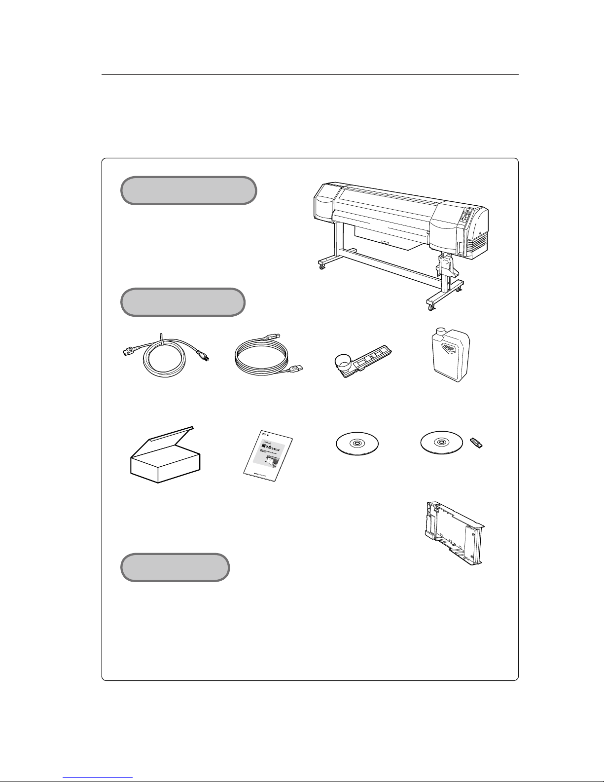
Components delivered with this product
Printer <1 unit>
- equipped with USB
interface
Starter kit
Choose one of the following.
- GX ink 6 colors
- GX ink 4 colors
- IX ink 6 colors
- IX ink 4 colors
CD-ROM
- CP Manager
- User's Guide
- Quick Reference Guide
<1 piece>
Waste ink bottle
<1 bottle>
- Ink is consumed during the initial lling when the printer is installed. Therefore, all of the ink may not
be used for printing.
- Some components may not be included or available depending on the purchase area.
Basic conguration item
Supplied Accessories
USB 2.0 cable
<1 piece>
Wiper sponge
<1 piece>
Power cord
<1 piece>
The following components are delivered with the product.
If any item is missing or damaged, contact the dealer where the printer was purchased or the nearest service representative.
Printer
CD-ROM
Installation Guide
<1>
PS RIP
<1 piece >
Required option
Print head kit
6 or 4 colors
Cartridge holder
<7 piece>
Page 8
ii
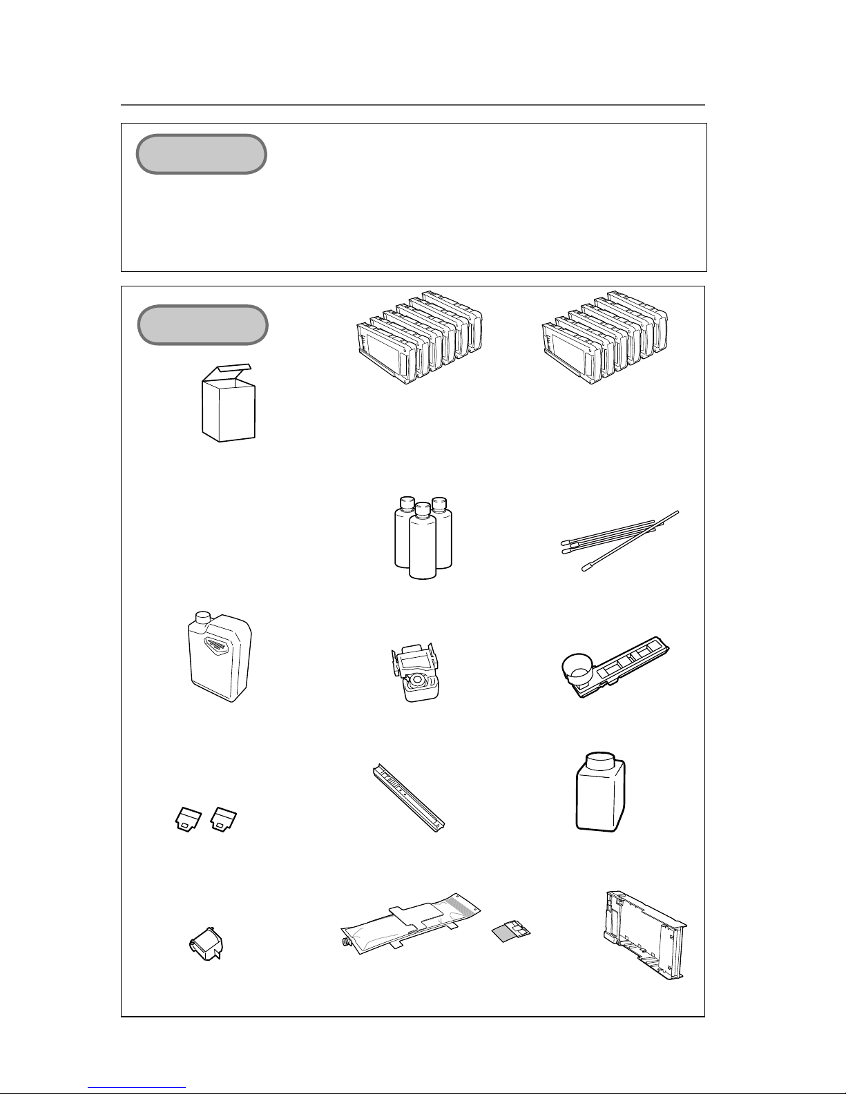
Cleaning roller set (IP5-147)
<30 pieces>
Media cutter blade (IP5-124)
(for cutter unit (64), cutter unit (54))
<1 piece>
Wiper sponge (IP5-123)
<1 piece>
Cap cleaning stick (IP5-120)
<1 piece>
(1 piece of cleaning roller is supplied.)
* Options and consumables are sold separately.
Daily maintenance kit (IP5-290 or IP5-296)
<1 set>
- Cap cleaning liquid : 300 ml
- Wiper cleaning liquid : 200 ml
- Cleaning Swab : 10 pieces
- Cleaning stick : 1 piece
- Cleaning roller : 30 pieces
- Wiper blade : 1 piece
- Tweezers : 1 piece
Cleaning liquid cartridge set
(IP5-294 or IP5-298)
<1 set>
- Cleaning liquid cartridge
: 6 pieces
Storage liquid cartridge set
(IP5-293)
(for both GX ink and IX ink)
<1 set>
- Storage liquid cartridge
: 6 pieces
Cap cleaning liquid set (IP5-292)
(for both GX ink and IX ink)
<1 set>
Wiper cleaning liquid set (IP5-291 or IP5-297)
<1 set>
- Wiper cleaning liquid (200 ml) : 3 bottles
Cleaning swab (IP6-147)
<300 pieces>
Options
Consumables
Waste ink bottle (IP5-299 )
<1 piece>
Wiper blade (IP5-122)
<2 pieces>
Ink cartridge for cartridge holder and board
(Y, M, C, K, Lc, Lm)
As to types, refer to P.1-13.
Cartridge holder
(IP5-320)
- Take-up reel unit (64) (IP-153) (for IP-5620) - Cutter unit (64) (IP5-262) (for IP-5620)
- Take-up reel unit (54) (IP5-260) (for IP-5520) - Cutter unit (54) (IP5-263) (for IP-5520)
- Blower unit (IP-182) - 6 color change kit (IP5-264)
- 2 inch flange (IP5-261)
- Exhaust attachment (IP-265)
Page 9
iii
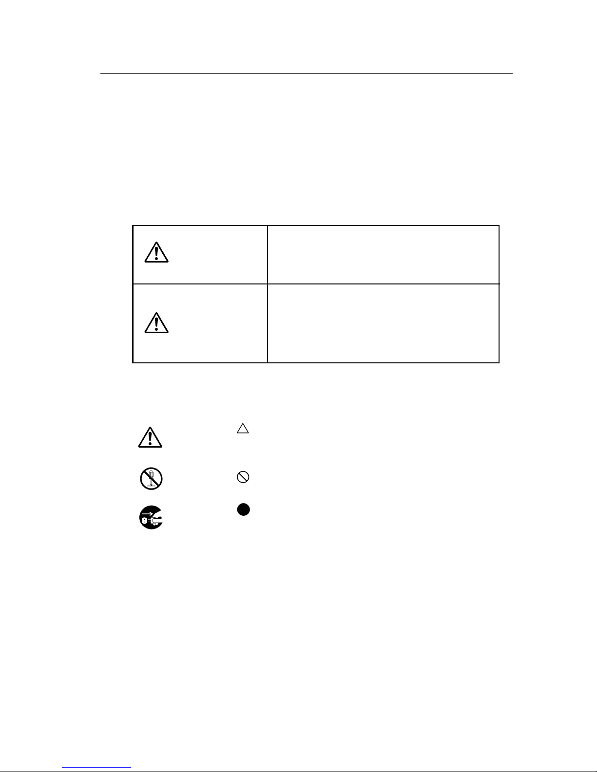
Example of symbols:
This symbol (
) denotes items that require special care
while executing a certain procedure or operation.
This symbol (
) denotes items that are forbidden.
This symbol (
) denotes items you should follow to pre-
vent accidents or injury.
Safety precautions
The following symbols are used in this manual to ensure proper use of the printer
and to prevent the printer from being damaged.
Follow the instructions marked with these symbols.
Failure to follow the guidelines
marked with this symbol could result
in minor personal injury or product
and/or peripheral damage.
Failure to follow the guidelines
marked with this symbol could result
in serious personal injury or death.
WARNING
CAUTION
Page 10
iv
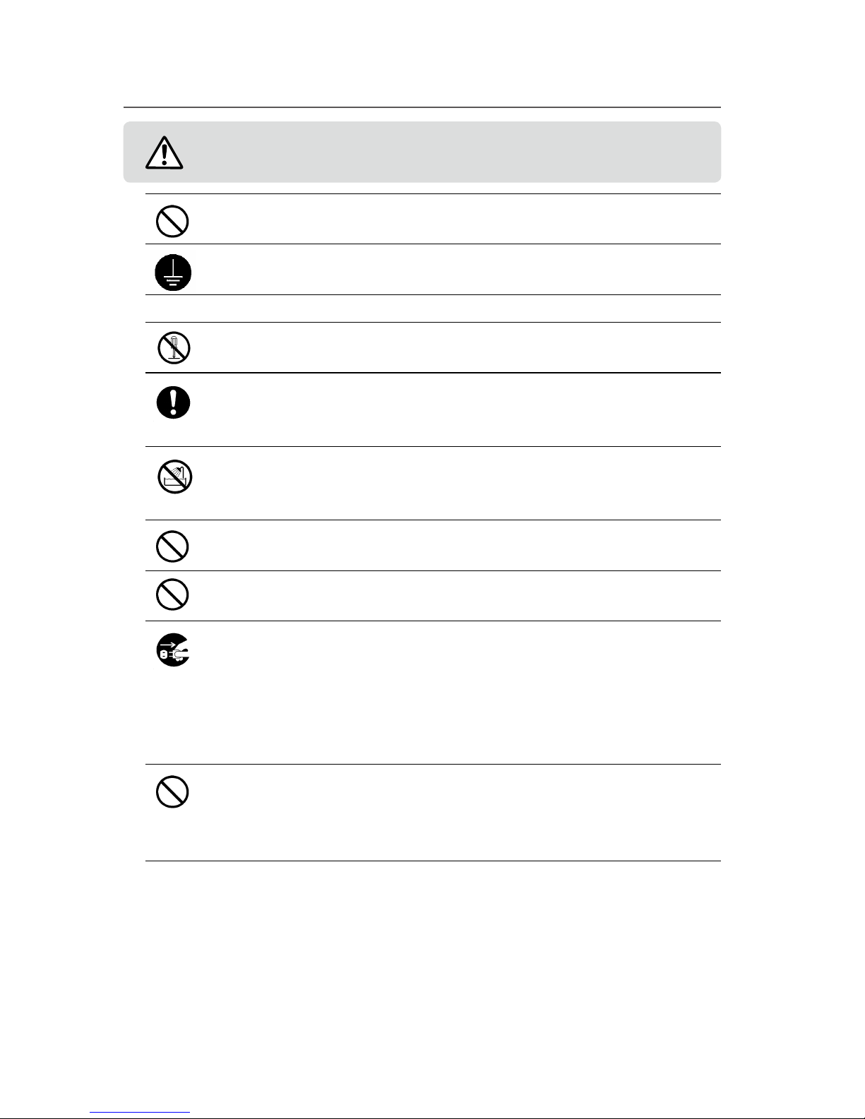
Use the power supply voltage specied on the nameplate. DO NOT plug several
devices into one electrical outlet as this might result in re or electric shock.
Make sure the printer is well grounded. If not, an electrical leak may cause re or
electrical shock.
DO NOT use electrical adapters.
DO NOT disassemble or repair the printer yourself. DO NOT block the vent. Do-
ing so may cause an accident or a malfunction.
DO NOT damage, break, process, or heat the power cable. DO NOT pull it,
bundle it up or put heavy weights on it. If it is damaged, replace it with a new
one. Using a damaged power cable may cause re or electric shock.
NEVER use the printer in a place of extreme humidity or any place where it can
possibly be splashed by any liquids. If any liquids get into the printer, it could
lead to re, electric shock, or personal injury.
DO NOT allow metal or liquids to touch the internal parts of the printer. Doing
so may cause re, electric shock, or personal injury.
DO NOT disconnect or connect the power cable with wet hands. Doing so may
lead to electric shock.
Power o the printer, unplug the power cable from the power outlet and ask a
service center for repair in any of the following cases. Using the printer in these
conditions may lead to personal injuries or re. Never repair the printer yourself.
- Smoke, strange noise or smells generate from the printer.
- A piece of metal or any liquid touches the internal parts or slot of the printer.
- An error requiring service by a service center occurs.
DO NOT put your hand unnecessarily inside the printer parts such as covers,
ventilator opening and ink cartridge slot. Doing so may result in personal injury.
Even if you do not operate the printer, it may perform a function automatically.
Use caution with the printer even if it is not printing.
WARNING
Be sure to read warnings below before use.
Page 11
v
The ink used for the device contains petroleum solvent. Since the ink is am-
mable, never operate near open ame.
DO NOT swallow ink, storage liquid, cleaning liquid, cap cleaning liquid, wiper
cleaning liquid or waste ink, and avoid contact with eyes. It will cause respirato-
ry distress and can harm the eyes. If it gets into the eyes, rinse with clean water
and consult a doctor immediately. If swallowed, do not try to induce vomiting.
Consult a doctor immediately.
Keep accessories and consumables such as ink cartridges and waste ink bottles
out of reach of children.
DO NOT place the printer on tables or unlevel areas where it could fall. If
dropped or falls, it may lead to injury. To prevent falling, lock the casters.
The heater becomes very hot. Be careful not to touch it as it may lead to burn
injuries.
Since the media rolls are heavy, handle them with care using a dolly or the like.
If dropped, personal injury may result.
Always operate the printer in a well ventilated area. Strong ink odor is gener-
ated that may cause discomfort for the user.
Always hold the power cord or the USB cable by the plug or the connector
when connecting or disconnecting the power cord or the USB cable. Never pull
on the cable because this may damage it and create risk of re, electric shock or
personal injury.
DO NOT get ink on your skin or clothes. Wash o any ink immediately with
soapy water.
Be sure to read cautions below before use.
In order to ensure the safe operation of the printer, note all of the cautions
and warnings contained throughout this manual.
CAUTION
Page 12

vi
Handling precautions
Power supply
1. Install the printer near an easily accessible electrical outlet.
2. Do not provide power to the printer through the same power line as for noise
generating devices, such as a motor.
3. Use the voltage specied on the nameplates of printer and option.
4. Turn o the power of the printer and check the following once a month.
1) The power plug is securely connected to the power outlet.
2) There is no dust on the power plug or the power outlet. Wipe o any dust
with a dry cloth.
5. Use only 15 A rated power strips.
6. If a power strip is used with the power cord, change it for a new one every year.
Printer
1. Do not place anything on top of the printer. Do not rest your elbows on the
printer. Handle it with care. Do not do anything that will result in impact to the
printer.
2. When opening or closing the cover, hold the center of the cover with both
hands and open or close it gently.
3. Before connecting or disconnecting the USB 2.0 cable, turn the printer o.
4. Do not clean the surface of the cover with benzene or paint thinner. The coating
may come o or deteriorate. Wipe the cover clean with a soft cloth. If the cover is
very dirty, use a cloth moistened with a neutral detergent. If the printer is stained
with ink, wipe it o immediately as it may aect the coating or the printer’s parts.
5. Handleaprintheadwithcare.•Donottouchitunnecessarilyorscratchit.•Do
not touch the bottom (nozzle surface).
6. The use of consumables, accessories and options other than the products specied by Seiko I Infotech aects the printed image quality, causes damage to the
printer and invalidate the warranty.
Page 13

vii
Maintenance
With regard to characteristics of solvent ink, the following maintenance must be
performed.
1. Check visually the remaining wiper cleaning liquid everyday.
2. Clean the Capping unit every week.
3. Perform the Print head cleaning [normal] every week.
4. Perform the service cleaning when leaving the printer for long time (2 weeks or
more) in power o state.
5. Perform the head wash and the ink charge before printing after you have left the
printer for long time.
For details about each maintenance, refer to [Section 4 Maintenance and Adjust-
ment / Replacement].
Consumables
1. Always use the recommended ink. Failure to do this may cause poor print quality
or printer damage that that may aect the printer functions.
2. Put a used ink cartridge into a plastic bag and dispose of it as industrial waste.
Observe local regulations for disposal.
3. Do not get ink on your skin or clothes. Wash o any ink immediately with soapy
water.
4. The level in the waste ink bottle must be periodically checked by visual inspection to prevent overow.
5. When the waste ink bottle is installed or removed, place a sheet below so as not
to stain the oor with spilled ink.
6. Store ink in a dark and cool place. NEVER store ink in a high temperature or direct
sunlight. Ink characteristics change if exposed to direct sunlight.
7. Ink, storage liquid, cleaning liquid, cap cleaning liquid, and wiper cleaning liquid
have expiration dates to ensure product quality. Use each consumable within the
expiration date.
8. Do not disassemble the ink cartridge.
9. The printer uses commercially available media designed for solvent ink. Be sure
to perform test prints as the print quality varies depending on the media.
Page 14
viii
Manual legend (Notational rules)
The notations used for text and keys / LCD in this guide are as follows.
Notations
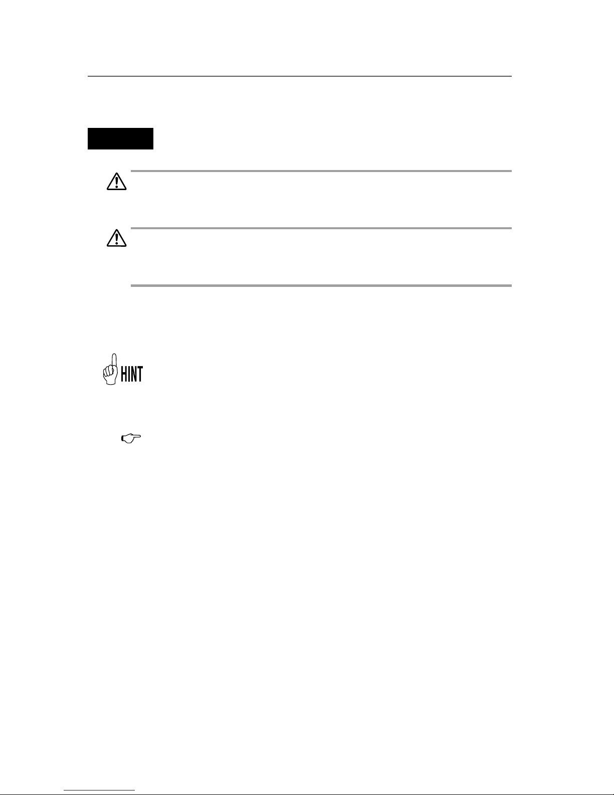
WARNING
- Boxes marked with a "WARNING" describe points of caution for avoiding
serious personal injury.
CAUTION
- Boxes marked with a "CAUTION" describe points of caution for avoiding
injury to yourself or damage to the printer.
Note
- They explain the important items and cautions that should be kept in mind
when operating the printer. To avoid troubles to the printer or prevent damages or wrong operation, be sure to read them.
Hint mark
The hint symbol describes operations that make using or handling the
printer easier.
Reference mark
This mark is followed by a reference section or page number.
Page 15
ix
h
REWIND FORM FEED
i
f
PH.REC PH.MAIN
g
PRINTER READY
ROLL : 1625 / PAPER
h
PRINTER SETUP
i
f
ADJUST HEATER
g
1
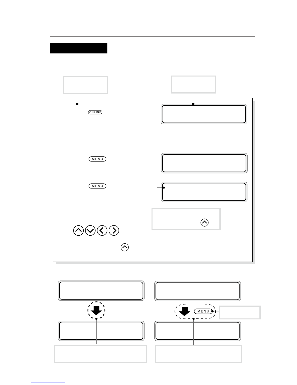
Press key to set the
printer oine. The menu
group (the rst layer menu)
is displayed.
2
Press key to enter in
the second layer menu.
3
Press key once more
to enter in the third layer
menu.
4
Select the menu with
keys.
For example, enter in the
function menu with
key.
Shows the key on
the operation panel.
Shows the LCD on
the operation panel.
Key / LCD notations
Shows the key to be used for
selection. (Example
h : key)
h
INK MEDIA REG
i
f
MEDIA M.ADV
g
h
REWIND FORM FEED
i
f
PH.REC PH.MAIN
g
(Example 2) Transition of LCD state in a sentence and the key operation
Shows that the LCD menu switches with
key operation.
INITIALIZING...
PLEASE WAIT
h
INK MEDIA REG
i
f
MEDIA M.ADV
g
Shows that the LCD menu automatically
changes without key operation.
Shows the key on the
operation panel.
(Example 1) Keys and LCD notations in a sentence
Page 16
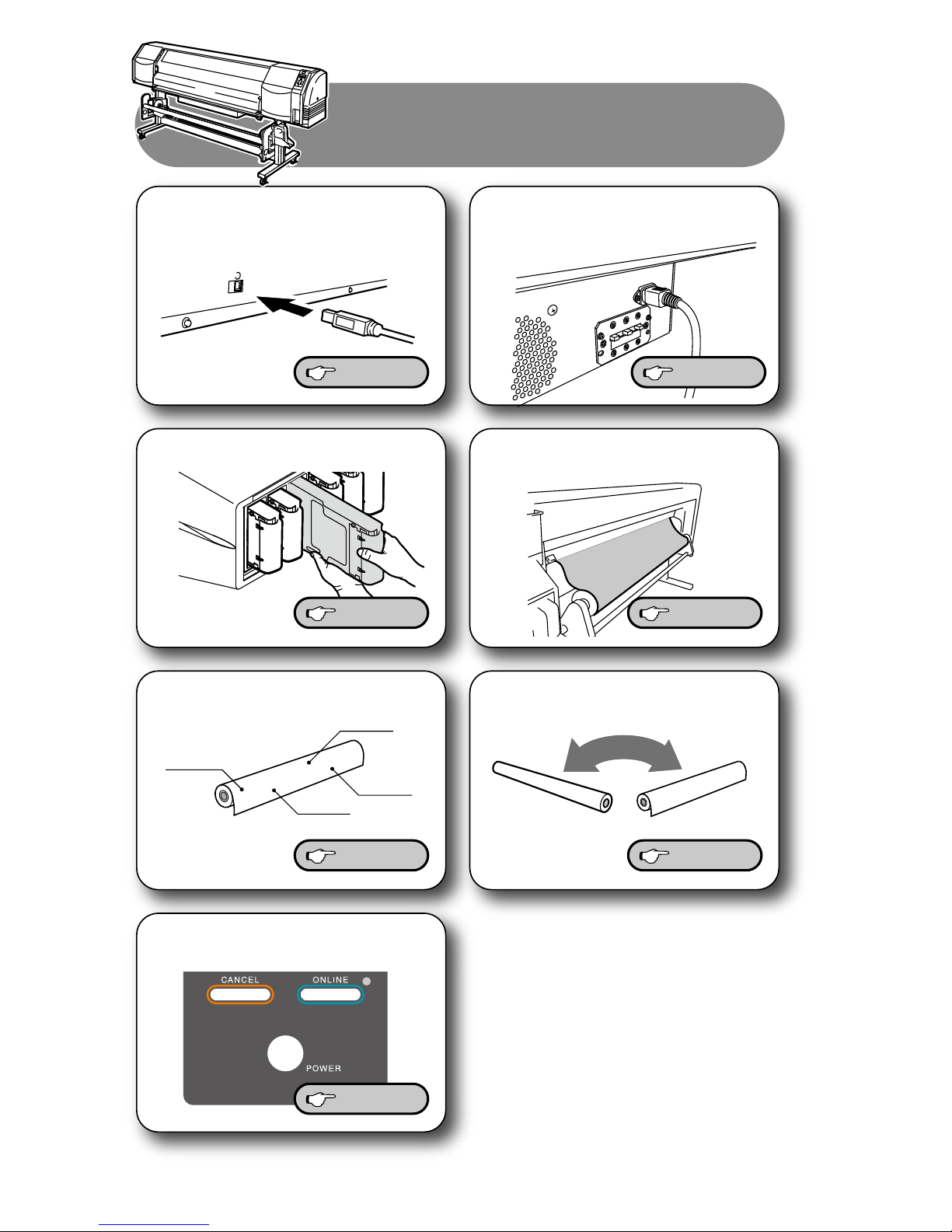
x
Media advance value
Media name
Head height
Print mode
Starting out...
Starting out...
Connect to a computer. Turn on the power.
Replace the ink cartridge. Load the roll media.
Replace the media.
Register the media.
Turn off the power.
P.2-2 P.2-3
P.2-30
P.2-12
P.2-3
P.2-7
P.2-15
Page 17
xi
2
4
1
3
65
#PH RECOVERY
>NORMAL
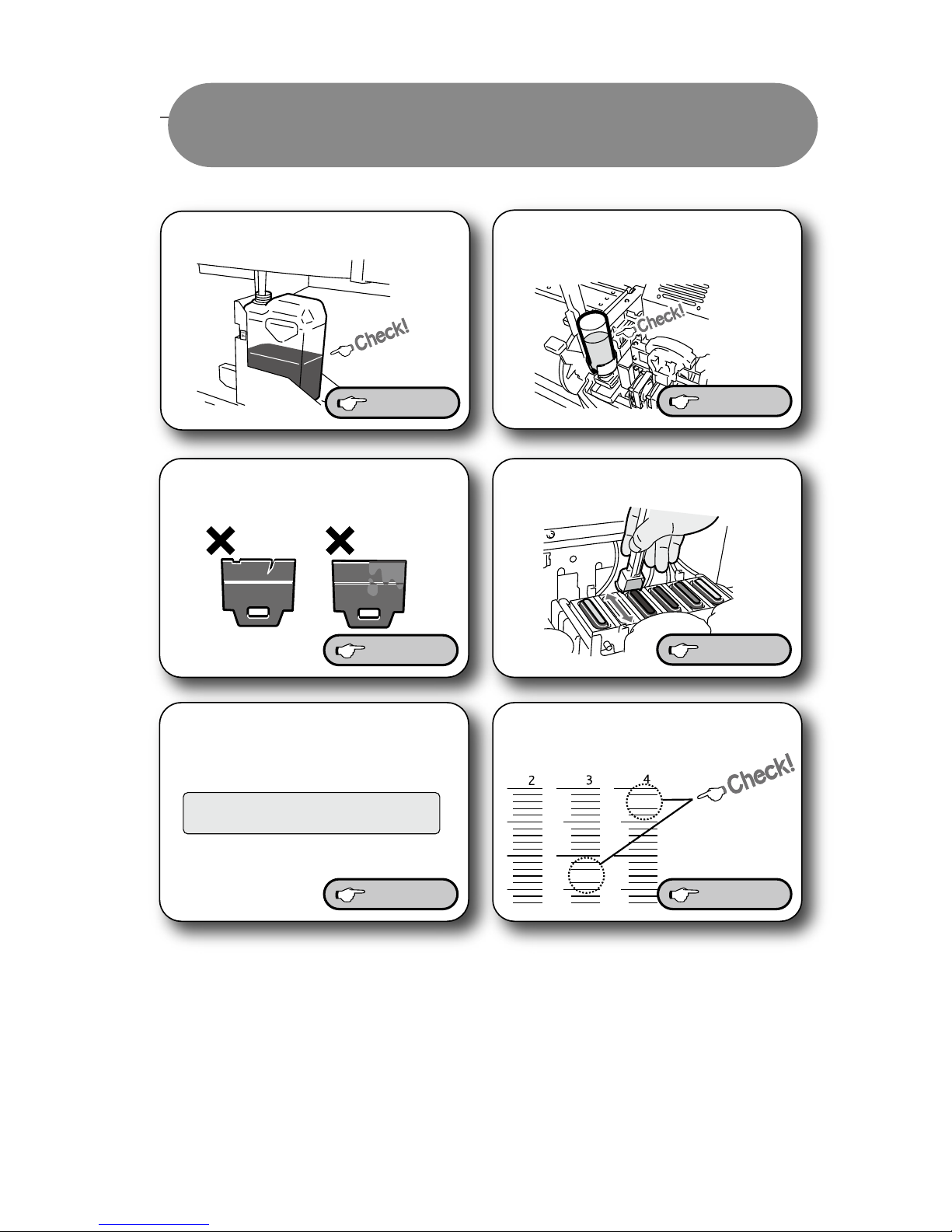
Regular Inspection (Maintenance)
Regular Inspection (Maintenance)
Clean the capping unit.
Check the Waste ink bottle.
Perform a nozzle print.
Check the wiper cleaning
liquid.
Check stains on the wiper
blade.
Perform a print head
cleaning [NORMAL].
P. 4-6
P. 4-3
P. 4-4
P. 4-3
P. 4-19 P. 4-8
Page 18
xii
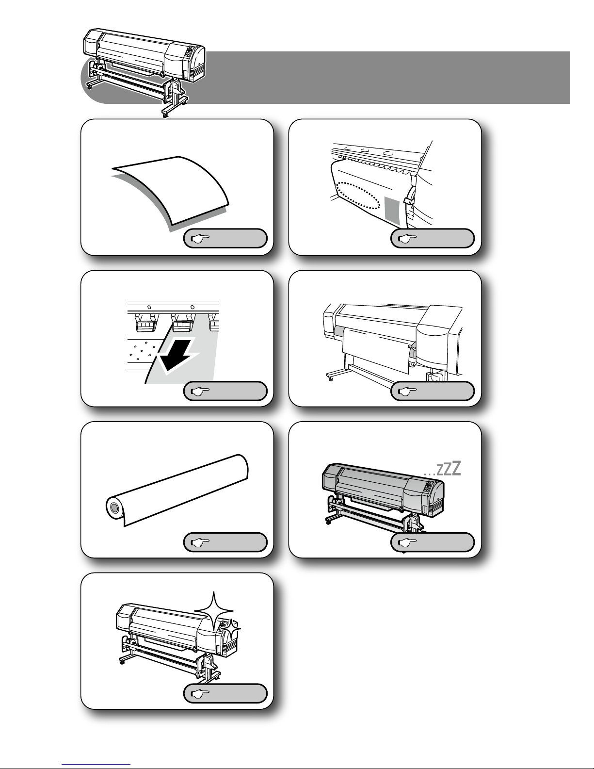
Change the media advance
value during printing.
Change the heater temperature
during printing.
Print on a thick media. Switch off the printer for a long
period of time.
Clean the printer.
Print on the margin of the media.
Print on the cut media (sheet).
When you want to . . .
When you want to . . .
P.2-17
P.2-23
P. 4-31 P.2-27
P. 2-28 P.4-10
P.4-14
Page 19
xiii
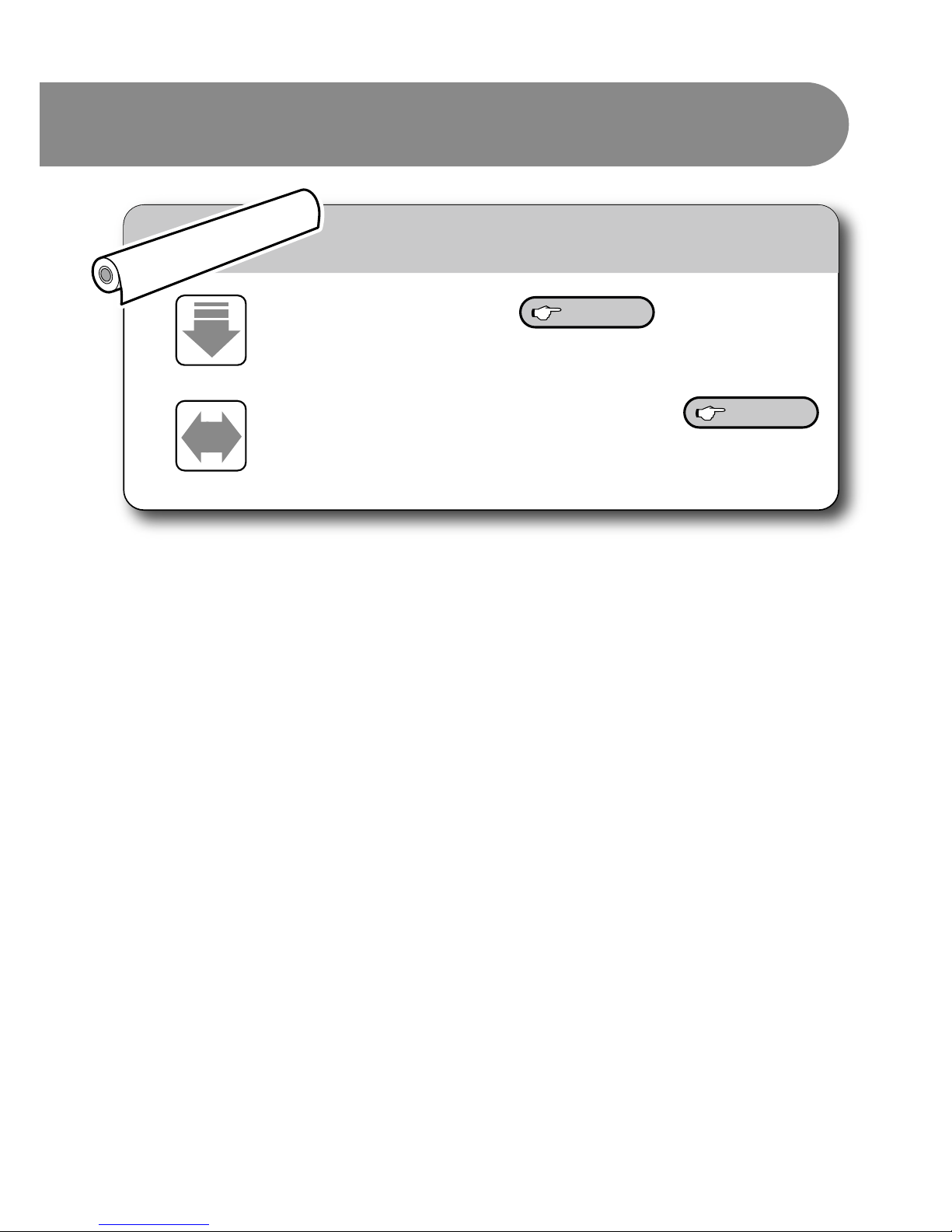
With new media, the printer needs to be adjusted.
With new media, the printer needs to be adjusted.
When replacing with a new media
Media advance value setting
Adjust the advance amount of the media.
Adjustment of the print head bidirection position
Adjust the ink target position during bidirectional printing.
P.4-27
P.4-33
Page 20
xiv
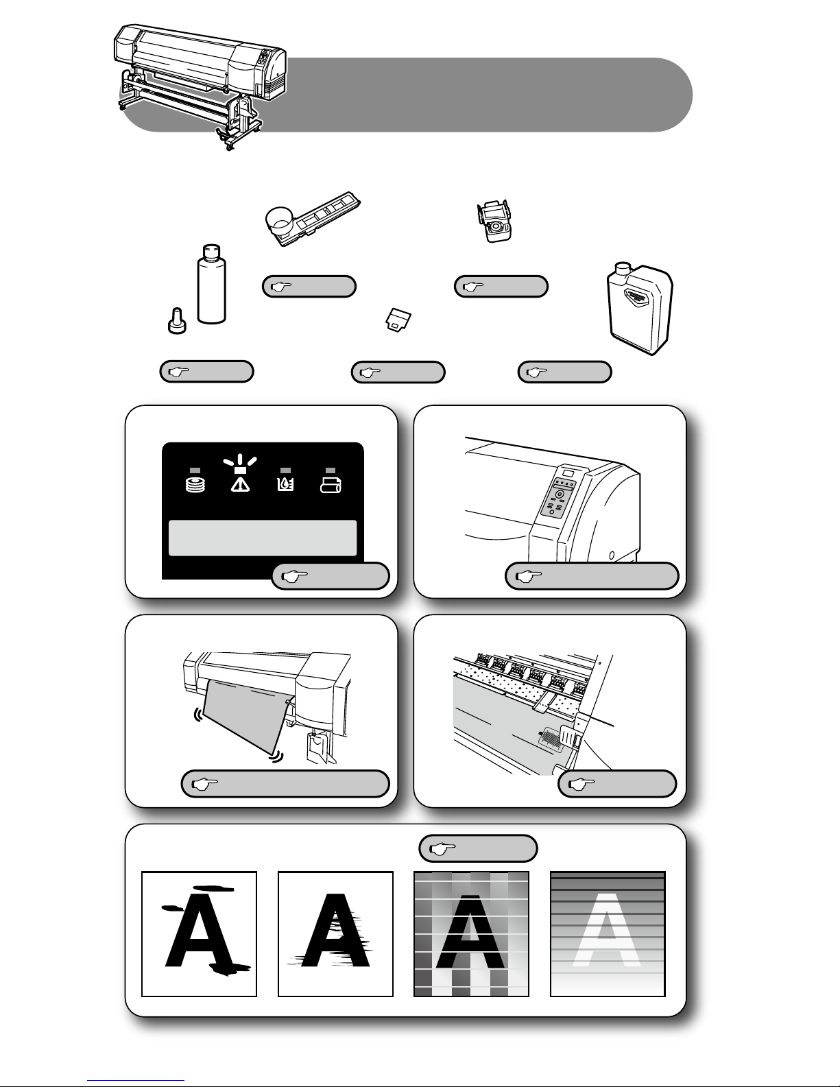
PERFORM DAILY
MAINTENANCE NOW
Replace consumables.
Wiper sponge
Wiper cleaning liquid
Media cutter blade
A warning message is displayed.
The heater does not warm up.The media is not straight.
Smears or stripes appear on the print.
The panel operation is not possible.
Wiper blade
Waste ink bottle
P.6-13 to
P.6-15 to
P.4-25 P.5-25
P.4-23
P.4-21
P.2-40
P.6-13, P.6-6
P.2-7, P.2-17, P.2-18
P.2-25
Replacement and trouble
Replacement and trouble
Page 21

C-1
TABLE OF CONTENTS
Components delivered with this product …………………………………… i
Safety precautions ………………………………………………………… iii
Handling precautions ……………………………………………………… vi
Manual legend (Notational rules) ………………………………………… viii
Overview
Operating conditions ……………………………………………………… 1-2
Installation space …………………………………………………………… 1-2
Environmental conditions ………………………………………………… 1-3
Appearance / Name and function of each part ……………………………1-4
Printer front (Paper exit side) ……………………………………………… 1-4
Printer rear (Paper feed side) ……………………………………………… 1-5
Print head …………………………………………………………………… 1-6
Capping unit ……………………………………………………………… 1-6
Heater ……………………………………………………………………… 1-7
Operation panel …………………………………………………………… 1-8
CP_Manager ………………………………………………………………… 1-9
Options …………………………………………………………………… 1-10
Exhaust attachment (IP-265) ……………………………………………… 1-10
2 inch ange (IP5-261) ……………………………………………………… 1-10
Blower unit (IP-182) ………………………………………………………… 1-10
Take-up reel unit (64) (IP-153) ……………………………………………… 1-11
Take-up reel unit (54) (IP5-260)……………………………………………… 1-11
Cutter unit (64) (IP5-262) …………………………………………………… 1-11
Cutter unit (54) (IP5-263) …………………………………………………… 1-11
6 color change kit (IP5-264) ………………………………………………… 1-11
Consumables …………………………………………………………… 1-12
Media ……………………………………………………………………… 1-12
Ink ………………………………………………………………………… 1-14
Waste ink bottle …………………………………………………………… 1-15
Daily maintenance kit ……………………………………………………… 1-16
Cap cleaning liquid ………………………………………………………… 1-17
Wiper cleaning liquid set …………………………………………………… 1-17
Cleaning stick ……………………………………………………………… 1-18
Cleaning roller set ………………………………………………………… 1-18
Cleaning swab ……………………………………………………………… 1-18
Wiper blade ………………………………………………………………… 1-18
Page 22

C-2
Media cutter blade ………………………………………………………… 1-18
Wiper sponge ……………………………………………………………… 1-18
Storage liquid cartridge set ………………………………………………… 1-19
Cleaning liquid cartridge set ……………………………………………… 1-19
LCD display and state of printer ………………………………………… 1-20
How to read LCD …………………………………………………………… 1-20
Basic operation
Connection to a computer ………………………………………………… 2-2
System conguration (Connection example) ……………………………… 2-2
Connecting procedure ……………………………………………………… 2-2
Power ON / OFF procedure ………………………………………………… 2-3
Power-on procedure ……………………………………………………… 2-4
Power-o procedure ……………………………………………………… 2-6
Media replacement ………………………………………………………… 2-7
Roll media installation procedure ………………………………………… 2-7
Roll media removal procedure ……………………………………………… 2-15
When replacing the roll media after it runs out …………………………… 2-16
When replacing the roll media due to jamming …………………………… 2-16
Cut media installation procedure …………………………………………… 2-17
Cut media removal procedure ……………………………………………… 2-17
When using 2 inch core rolls ……………………………………………… 2-18
How to use the media edge guards ……………………………………… 2-19
How to switch the pressure ……………………………………………… 2-20
Feeding the media [Feed] ……………………………………………… 2-21
Rewind the media [Back Feed] …………………………………………… 2-22
How to use the origin setting function ………………………………… 2-23
Changing temperature using the heater control menu …………………… 2-25
Change the Print head height …………………………………………… 2-28
Ink cartridge replacement ……………………………………………… 2-30
Ink cartridge replacement procedure ……………………………………… 2-30
When the ink cartridge is empty and it needs to be replaced ……………… 2-31
When no ink cartridge is installed ………………………………………… 2-31
When the ink cartridge is not recognized ………………………………… 2-31
Reloadable cartridge replacement ……………………………………… 2-32
Used ink cartridge removal procedure ……………………………………… 2-33
Ink cartridge installation procedure ………………………………………… 2-35
Waste ink bottle replacement …………………………………………… 2-40
Waste ink bottle replacement procedure …………………………………… 2-40
When no waste ink bottle is installed ……………………………………… 2-42
The media was skewed. ………………………………………………… 2-43
Page 23

C-3
Menu of Operation panel
Basic menu operation in oine mode ……………………………………3-2
Menu layer structure ……………………………………………………… 3-3
Menu tree ………………………………………………………………… 3-4
Basic operation procedure and keys used ………………………………… 3-10
Procedure selection, numerical input, execution and character input ……… 3-11
Explanation of each menu operation …………………………………… 3-17
INK MENU …………………………………………………………………… 3-17
MEDIA MENU ……………………………………………………………… 3-18
MEDIA REG MENU ………………………………………………………… 3-20
M.ADV MENU ……………………………………………………………… 3-40
REWIND MENU ……………………………………………………………… 3-46
PH.REC MENU ……………………………………………………………… 3-47
FORM FEED MENU ………………………………………………………… 3-48
PH.MAIN MENU …………………………………………………………… 3-49
PRINTER MENU ……………………………………………………………… 3-52
ADJUST MENU ……………………………………………………………… 3-53
SETUP MENU ……………………………………………………………… 3-57
HEATER MENU ……………………………………………………………… 3-62
Maintenance and Adjustment / Replacement
Periodic maintenance ……………………………………………………… 4-2
Periodic inspection and maintenance guide ……………………………… 4-2
Cleaning …………………………………………………………………… 4-14
Print head cleaning ……………………………………………………… 4-19
Operating procedure of print head cleaning ……………………………… 4-19
Wiper blade replacement ………………………………………………… 4-21
Wiper cleaning liquid replacement ……………………………………… 4-23
Wiper sponge replacement ……………………………………………… 4-25
Media advance value setting …………………………………………… 4-27
Media advance value setting procedure …………………………………… 4-27
Change during online printing …………………………………………… 4-31
Head position adjustment ……………………………………………… 4-32
BIDIRECTIONAL ADJUSTMENT method …………………………………… 4-33
[PRINT HEAD ADJUST] adjustment procedure ……………………………… 4-38
[EDGE SENSOR ADJUST] adjustment procedure …………………………… 4-41
Page 24

C-4
How to use options
How to use the take-up reel unit ……………………………………………5-2
Install the media on the take-up reel unit ………………………………… 5-2
Tension take-up / Loose take-up setting …………………………………… 5-6
Take-up switch setting ……………………………………………………… 5-7
Using a 2 inch core ………………………………………………………… 5-8
When the media cannot be winded in loose take-up conguration ……… 5-9
Adjustment of the take-up reel unit …………………………………… 5-18
Initial adjustment …………………………………………………………… 5-18
Adjustment during operation ……………………………………………… 5-20
How to use the blower unit (option) …………………………………… 5-22
Normal utilization …………………………………………………………… 5-22
Handling the media ………………………………………………………… 5-23
Cut the media …………………………………………………………… 5-24
Media cutter blade replacement ………………………………………… 5-25
Troubleshooting
When encountering a problem …………………………………………… 6-2
How to clear media jams …………………………………………………… 6-6
When an error message is displayed ……………………………………… 6-7
Service call error …………………………………………………………… 6-7
Operator call error ………………………………………………………… 6-8
When a warning message is displayed ………………………………… 6-13
How to get good image quality ………………………………………… 6-15
Abnormal sound ………………………………………………………… 6-23
Appendix
Basic specications …………………………………………………………A-2
Printer Specications ……………………………………………………… A-2
Options / Consumables ……………………………………………………A-3
Options …………………………………………………………………… A-3
Consumables ……………………………………………………………… A-3
Page 25

This section describes the information needed before using
the printer (basic knowledge). After reading this section,
proceed to section 2.
Overview
Operating conditions........................................................1-2
Appearance / Name and function of each part ......1-4
CP_Manager ......................................................................... 1-9
Options ................................................................................1-10
Consumables .....................................................................1-12
LCD display and state of printer ..................................1-20
(Content in this section)
1
Page 26
1-2
Operating conditions
This section describes the operating conditions required for the printer.
Installation space
The adequate space is required around the printer for normal operations,
including consumables replacement, print processing, blower unit shifting and
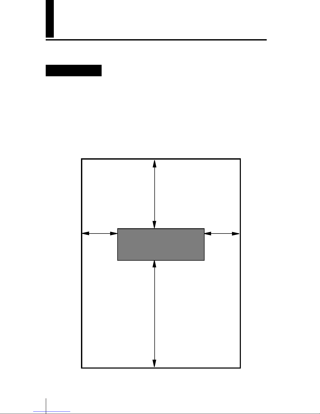
ventilation, as well as parts replacement for repairing. Be sure to secure the space
indicated in the picture below.
¢ Installation and maintenance space
Height direction : 1750
(Unit : mm)
400mm, 16 inches
400mm, 16 inches
2000mm, 80 inches
1000mm, 40 inches
(Front side)
Page 27

Overview
1-3
1
Environmental conditions
¢ Operating temperature and humidity ranges
The printer should be used within the temperature and humidity ranges shown
below.
Temperature : 15 °C to 30 °C (60 °F to 86 °F)
Humidity : 30% to 70%
¯To obtain better print quality, use the printer within temperatures of 20 to
25 °C (68 °F to 77 °F.)
¯To keep a stable and good print quality, the printer slows down the print
speed when the operating temperatures exceeds 41 °C (106°F).
Note
- When the printer is used out of the operating temperature and humidity
ranges, the print quality may be degraded and/or print may be stopped.
-
It takes time for the printer to adapt to the operating environment temperature
and humidity. To get good printed image quality, it is recommended to keep the
room temperature 20 to 25°C , 68 to 77°F and use the printer after at least 1 hour.
¢ Places where the printer must not be installed
Do not install the printer in the following places:
¯ Places exposed to direct sunlight
¯ Places subject to vibration
¯ Places with excessive dust
¯ Places subject to extreme changes in temperature or humidity
¯ Places near an air conditioner or a heater
¯ Places where the printer may get wet
¯ Places subject to direct air circulation from vents
¯ Places near a diazo copier that may generate ammonia gas
¯ Places with poor ventilation
¯ Unstable places
Page 28
1-4
Appearance / Name and function of each part
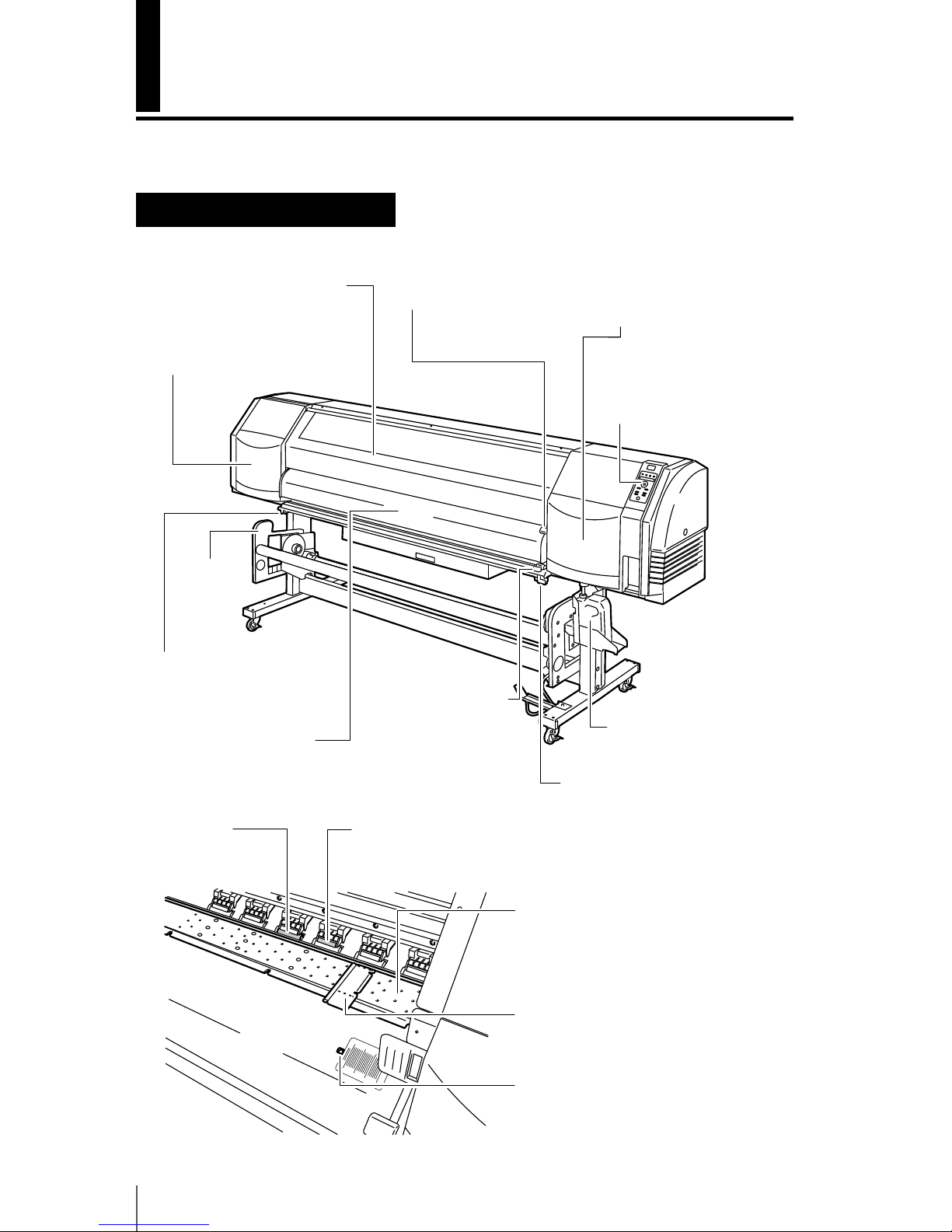
The printer is shown with the name and function of each component.
Printer front (Paper exit side)
Front cover
Close it when printing.
Pressure roller up/down lever
This lever xes or releases the
media.
Maintenance cover
Open it when performing the print
head maintenance (replacement
and height adjustment).
Media clip (option)
After cutting the media, clip it
to not let it fall.
Grit roller
The grit roller
advances or rewinds
the media.
Media cutter blade
(option)
It cuts the media.
Waste ink bottle
Media clip (option)
After cutting the media,
clip it to not let it fall.
Pressure roller
When lowering the pressure
roller up/down lever, it pinches
the media.
Platen
It is the media path. To prevent
the media from oating, a suction
fan is built in it, as well as a heater
to x the ink.
Media edge guard
It protects the print head from curls
and irregularities at both edges of a
media.
Paper ejection sensor
It detects the presence/absence of a
media.
Cap cover
Open it when cleaning the
capping unit or replacing the
wiper blade.
Operation panel
Includes the lamps and LCD to
display the status of the printer
and keys to set the various
functions.
Front paper guide
Includes the after heater used
to dry the ink.
Take-up reel
unit (option)
Page 29
Overview
1-5
1
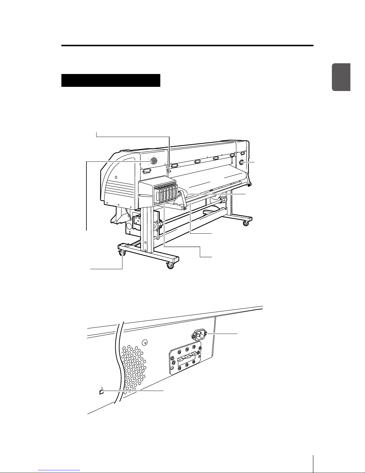
Printer rear (Paper feed side)
Pressure roller up/down lever
This lever xes or releases the media. It is
inter-linked with the pressure roller
up/down lever on the front of the printer.
Exhaust attachment
(option) installation
location
Exhaust attachment
(option) installation
location
Media holder
To be installed at both
ends of the roll media.
Flange holder
Place the media with ange
on the ange holder.
Caster
Set the lock to OFF when moving
the printer and set the lock to ON
when locking the printer.
Ink cartridge slot
Set the ink cartridges in these slots.
Power inlet
Connect the power
cable to the power inlet.
USB connector
Connect the USB 2.0 cable to the
USB connector.
Page 30
1-6
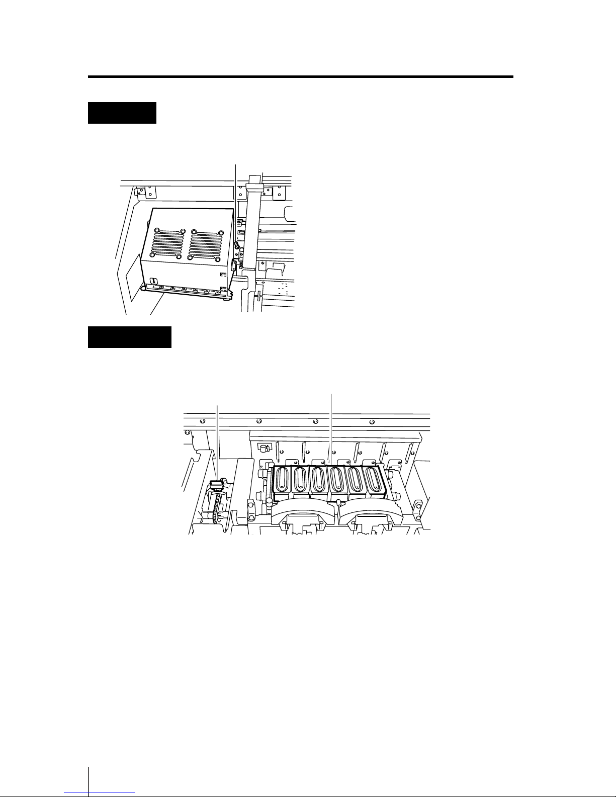
Print head
Capping unit
Head up down mechanism
By lowering the lever, the print
head position rises by 0.5mm.
Wiper blade
It removes foreign matters
on the surface of the
nozzles of the print head.
Capping unit
It prevents the nozzles of the
print head from drying.
Page 31
Overview
1-7
1
Heater
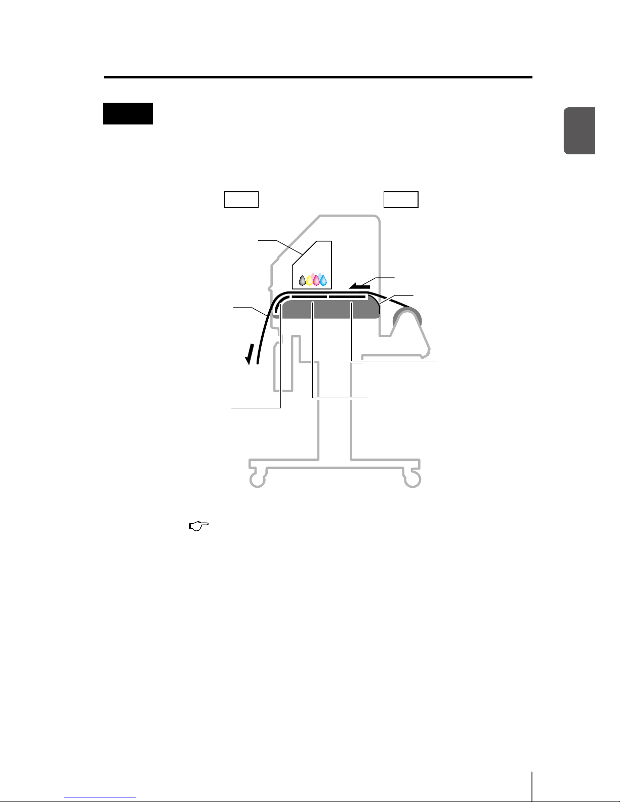
This printer is equipped with three heaters for ink fusing and image quality
stabilization.
* These three heaters are controlled independently.
( P.2-41 [Changing temperature using the heater control menu])
Front Rear
q Appearance / Name and function of each part
Preheater
Preheats the media.
Print heater
Make the ink penetrate into the
media to fuse the ink.
After heater
Dries ink to stabilize print quality.
Media feed direction
Media
Carriage
Paper guide(rear)
Print head
Page 32
1-8
Operation panel
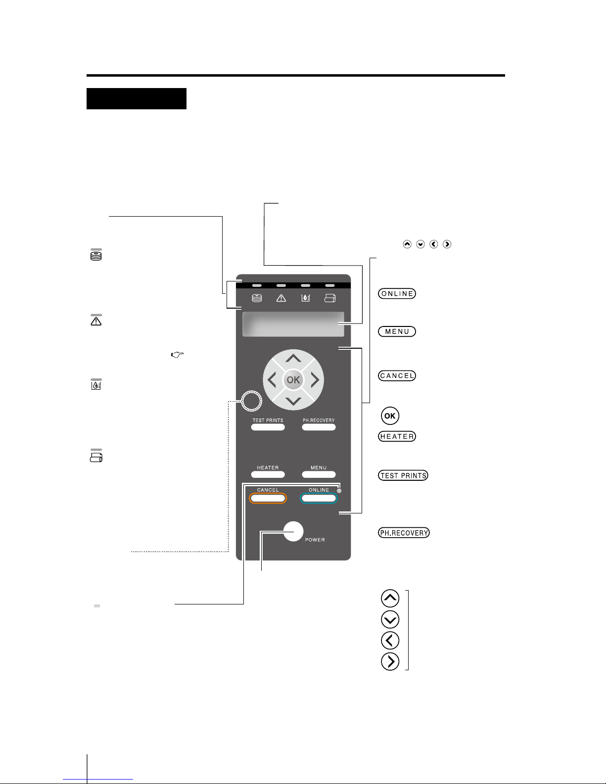
The keys, LEDs and LCD are laid on the operation panel of the printer as shown
below. The buzzer is to notify the operator when an error occurs or an invalid key
is pressed.
LCD
It shows the status of the printer and displays the menu window. It
displays various message and status in alpha-numeral, KANA and
symbols (2 rows, 20 characters). The menu adopts the layer structure.
Each menu can be accessed with the keys or menu
key.
LED
ON, blinking and OFF indicate the
status of the printer.
Data LED (Green)
It indicates the data reception state
-
Blinking:
The printer is receiving data
from a computer.
- OFF: No data reception from a
computer
Error LED (Orange)
It indicates the presence/absence
of an error.
- ON: An error occurred.
- Blinking: Warning ( P.6-13)
- OFF: Normal (no error)
Ink LED (Green)
It indicates the presence/absence of
ink.
- ON: All inks are present.
- Blinking: Remaining ink is low.
Near expiration date of ink in use
- OFF: No ink
Media LED (Green)
It indicates the presence/absence of
a media.
- ON: Media is present
(either roll media or cut media is
loaded.)
- Blinking: Take-up time out
- OFF: No media
(neither roll media nor cut media)
ONLINE LED
It indicates the online/oine
state of the printer.
- ON: Online
- Blinking: Print pause mode
- OFF: Oine
Buzzer
Sounds at an error occurrence, warns
an invalid key entry, daily maintenance
and the uncapped print head.
Power switch
Used to turn on or o the
power of the printer.
Key
Use the keys for menu operation
of the printer.
Used for switching the printer
online/oine.
Used as the input auxiliary (switches
the layer display of the menu) key for
the parameters.
Used to cancel the entered parameter.
Used to conrm the menu and
parameters.
Used to enter heater control menu.
Short press: Use to enter the ADJUST
menu.
Long press: Use to enter the M.ADV
menu.
Short press: Use to enter the PH.REC
menu.
Long press: Use to enter the PH.MAIN
menu.
Used for selecting the menu
group and switching the
menu (selection,
increase/decrease numeral
value).
Page 33
Overview
1-9
1
CP_Manager
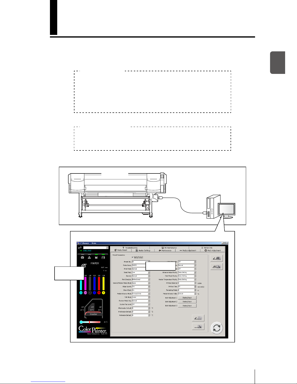
The Printer supports the CP_Manager software that provides a general view of the
Printer status. The following operations can be performed with CP_Manager™.
- Display Printer status
- Create media preset, input adjustment values
- Execute nozzle printing, adjustment patterns printing
- Maintenance time notice, maintenance operation.
- Display operation guidance
- Display the instruction manual (PDF)
Install CP_Manager™ using the CD-ROM supplied with the Printer.
Panel operations
Additional functions
Computer
USB interface
Printer
Printer status
display
Media preset
CP_Manager display example
Page 34
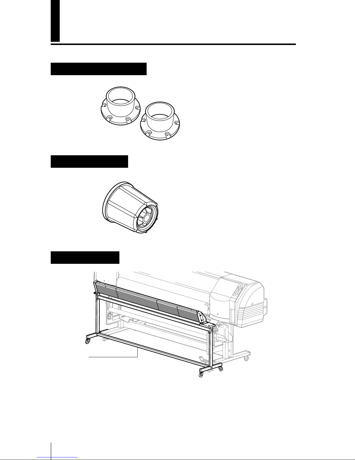
1-10
Options
Exhaust attachment (IP-265)
An optional unit to attach an exhaust duct to the printer.
2 inch ange (IP5-261)
This ange is used to load the roll media of 2 inch core.
Blower unit (IP-182)
Blower unit
This unit dries ink by sending air
to the media.
Page 35

Overview
1-11
1
Take-up reel unit (64) (IP-153)
This unit is used to reel in the printed media. (For IP-5620)
Take-up reel unit (54) (IP5-260)
This unit is used to reel in the printed media. (For IP-5520)
Cutter unit (64) (IP5-262)
This unit is used to cut the printed media manually. (For IP-5620)
Cutter unit (54) (IP5-263)
This unit is used to cut the printed media manually. (For IP-5520)
6 color change kit (IP5-264)
This kit is used to upgrade a 4 color specications printer to 6 color specications.
Page 36

1-12
Consumables
Media
¢ Type of media
The printer uses the following commercially available media for solvent ink.
Printing conditions may vary depending on the installation environment and
the media lot. We recommend you perform test prints before printing. For more
details, contact your dealer or Seiko I Infotech sales.
- Glossy vinyl chloride
- Matte vinyl chloride
- Tarpaulin
¢ Precautions for storing media
¯ Avoid direct sunlight and water regardless of before and after opening
the package. Put media in plastic to prevent exposure to dust and store
media in a dry, cool and dark place.
¯ Avoid rapid change of temperature and humidity and store media in a
place with no condensation.
¯ Do not store media in standing position to prevent unraveling of media
and damage to roll edge.
¯ Do not pile up media rolls.
¢ Precautions for disposing of media
¯ Dispose of media and printouts in a manner consistent with local
regulations.
Page 37

Overview
1-13
1
¢ Precautions for preparing media
¯ Avoid a change in temperature and humidity after opening the
package. Load media after leaving the media in the operation
environment for 3 hours or more. Be careful of humidity changes when
turning air conditioners ON or OFF.
¯ Curl of paper in low humidity and wrinkle of media in high humidity
may occur depending on the media characteristics. Use paper in normal
temperature and humidity environment (around 23 °C, 73 °F and 50%
RH).
¯ Do not damage the media. The roll edges are important for media
feeding. Also, do not drop or wet the media. Doing so may cause print
quality problems or damage to the printer.
¯ Hold edges of the media so as not to touch the print surface. Soiling the
print surface may cause poor print quality.
¯ Fix unraveling of the roll media before loading.
¢ Precautions for handling prints.
¯ Do not touch the print surface before the ink dries. Handle by the edges
of the media. Attention must be paid during the rst 24 hours.
¯ Rubbing print surface causes color fading or color transfer. To prevent
color transfer, do not stack prints.
¯ Do not stack printed media on printouts from copier or laser printer. This
may damage the prints.
¯ Do not rub, scratch, or fold the printed surface of media. Color may be
lost or the surface (coated layer of the media) may come o.
¯ Do not leave the paper in wet environment.
¢ Other precautions of media
¯ Old media may change in quality or cause color fading. Use media in
good conditions.
¯ Dust and debris produced when cutting the media may damage the
media.
¯ When an adhesive media is used, the platen may be stained with
adhesive from the media. In this case, wipe the adhesive o the
platen, referring to [Section 4 Maintenance and Adjustment /
Replacement]. Otherwise, the adhesive may cause media jams.
¯ Print quality varies depending on media. Always check your printouts.
Page 38
1-14
Ink
¢ Ink types
Use only the recommended ink cartridges listed below.
(Ink cartridges using the cartridge holder)
Type Content
Quantity
Type Content
Quantity
IP5-301 Y (Yellow) (GX ink) 500 ml IP5-311 Y (Yellow) (IX ink) 500 ml
IP5-302 M (Magenta) (GX ink) 500 ml IP5-312 M (Magenta) (IX ink) 500 ml
IP5-303 C (Cyan) (GX ink) 500 ml IP5-313 C (Cyan) (IX ink) 500 ml
IP5-304 K (Black) (GX ink) 500 ml IP5-314 K (Black) (IX ink) 500 ml
IP5-305 Lc (Light cyan) (GX ink) 500 ml IP5-315 Lc (Light cyan) (IX ink) 500 ml
IP5-306 Lm (Light magenta) (GX ink) 500 ml IP5-316 Lm (Light magenta) (IX ink) 500 ml
* When using IP5-3xx inks, a cartridge holder (IP5-320) is required for each color.
Note
- Use only the recommended ink cartridges.
- Failure to use the recommended ink cartridges may lead to a deterioration of
the print quality or a printer malfunction. In this condition, proper operation
of the printer cannot be guaranteed.
- The GX ink expiration date is 14 months from the date of production.
- The IX ink expiration date is 12 months from the date of production.
- Using an ink cartridge after the expiration date may lead to a deterioration
of the print quality or a printer malfunction.
- Store ink cartridges in cool and dark places.
- Do not agitate ink cartridges before use.
- Install all the 6 ink cartridges (4 when 4 color specications). If you remove
any of the cartridges, install a new one.
- All the used ink cartridges must be of the same type (GX ink or IX ink)
- Contact your dealer or a sales representative to change the ink type.
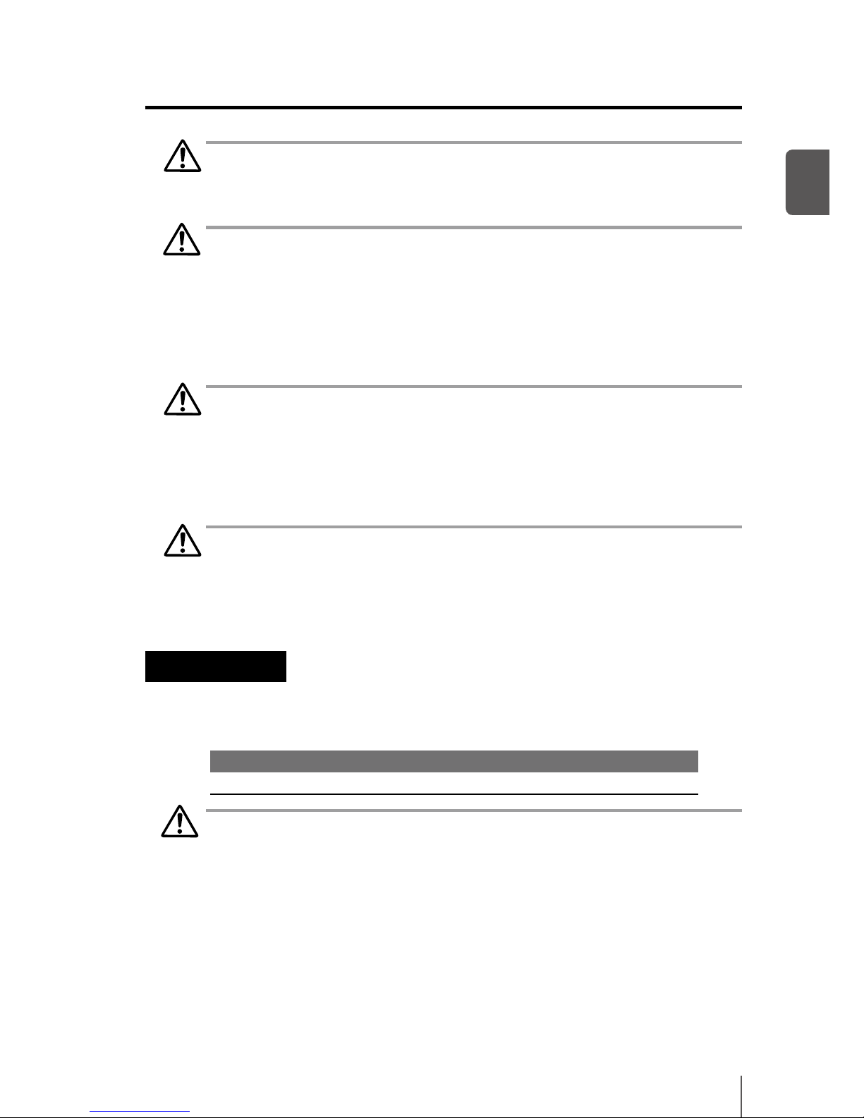
Ink cartridges must be installed in all the 6
slots (4 when 4 color specications). Each
color must be installed in its dedicated slot.
(See the gure to the right)
Yel low
Magenta
Cya n
Black
Light magenta (6 color specif ications only)
Light cyan (6 color specifications only)
Page 39
Overview
1-15
1
Note
- Do not force ink cartridges in the wrong slot.
WARNING
- Never place the ink close to open ames. Doing so will create a re hazard.
- Do not swallow ink and avoid contact with eyes. It will cause respiratory
distress and can harm the eyes. If it gets into the eyes, rinse with clean water
and consult a doctor immediately. If it is swallowed, do not try to induce
vomiting. Seek medical attention immediately.
Note
- Do not disassemble the ink cartridge.
¢ Precautions for ink storage and processing
Note
Put a used ink cartridge into a plastic bag and dispose of it as industrial waste.
Observe local regulations for disposal.
Waste ink bottle
Use the recommended waste ink bottle listed below.
Type Content Quantity
IP5-299 Waste ink bottle 1 piece
WARNING
- Never put the waste ink bottle near open ames. Doing so may cause a re
hazard.
- Do not swallow waste ink and avoid contact with eyes. It will cause
respiratory distress and can harm the eyes. If it gets into the eyes, rinse with
clean water and consult a doctor immediately. If it is swallowed, do not try to
induce vomiting. Seek medical attention immediately.
q Consumables
Page 40

1-16
Note
- Install the waste ink bottle securely.
- A waste ink bottle must always be installed. If it is removed for replacement,
a new one (empty) must be installed.
¢ Precautions for handling the waste ink bottle
Note
- After use, securely fasten the attached cap and dispose of this product as
industrial waste. Observe local regulations for disposal.
- Always wear gloves when you dispose of waste ink.
Daily maintenance kit
Use the following cleaning liquid, cleaning stick, cleaning roller, cleaning swab,
wiper blade, and tweezers specied by Seiko I Infotech.
Type Content
Quantity
Type Content
Quantity
IP5-290 Daily maintenance kit
(for GX ink)
1 set
IP5-296 Daily maintenance kit
(for IX ink)
1 set
Cap cleaning liquid
300 ml
Cap cleaning liquid
300 ml
Wiper cleaning liquid
(for GX ink)
200 ml
Wiper cleaning liquid
(for IX ink)
200 ml
Cleaning swab
10 pieces
Cleaning swab
10 pieces
Cleaning stick
1 piece
Cleaning stick
1 piece
Cleaning roller
30 pieces
Cleaning roller
30 pieces
Wiper blade
1 piece
Wiper blade
1 piece
Tweezers
1 piece
Tweezers
1 piece
WARNING
- Do not swallow cleaning liquid and avoid contact with eyes. It will cause
respiratory distress and can harm the eyes. If it gets into the eyes, rinse with
clean water and consult a doctor immediately. If it is swallowed, do not try to
induce vomiting. Seek medical attention immediately.
- Do not keep the cap cleaning liquid and the wiper cleaning liquid in a high
temperature place or in direct sunshine. Never place the cap cleaning liquid
and the wiper cleaning liquid close to open ames. Doing so will create a re
hazard.
Note
- Use the wiper cleaning liquid only for the designated purpose.
Page 41

Overview
1-17
1
Cap cleaning liquid
Use the following cap cleaning liquid specied by Seiko I Infotech.
Type Content Quantity
IP5-292 Cap cleaning liquid (for both GX and IX inks) (300 ml) 1 piece
WARNING
- Do not swallow cap cleaning liquid and avoid contact with eyes. It will cause
respiratory distress and can harm the eyes. If it gets into the eyes, rinse with
clean water and consult a doctor immediately. If it is swallowed, do not try to
induce vomiting. Seek medical attention immediately.
- Do not keep the cap cleaning liquid bottle in a high temperature place or in
direct sunshine. Never place the cap cleaning liquid close to open ames.
Doing so will create a re hazard.
Wiper cleaning liquid set
Use the following wiper cleaning liquid specied by Seiko I Infotech.
Type Content Quantity
IP5-291 Wiper cleaning liquid (for GX ink) (200 ml) 3 pieces
IP5-297 Wiper cleaning liquid (for IX ink) (200 ml) 3 pieces
WARNING
- Do not swallow wiper cleaning liquid and avoid contact with eyes. It will
cause respiratory distress and can harm the eyes. If it gets into the eyes, rinse
with clean water and consult a doctor immediately. If it is swallowed, do not
try to induce vomiting. Seek medical attention immediately.
- Do not keep the wiper cleaning liquid bottle in a high temperature place
or in direct sunshine. Never place the wiper cleaning liquid close to open
ames. Doing so will create a re hazard.
q Consumables
Page 42

1-18
Cleaning stick
Use the following cleaning stick specied by Seiko I Infotech.
Type Content Quantity
IP5-120 Cleaning stick (for both GX and IX inks) 1 piece
Cleaning roller (for both GX and IX inks) 1 piece
Cleaning roller set
Use the following cleaning roller specied by Seiko I Infotech.
Type Content Quantity
IP5-147 Cleaning roller (for both GX and IX inks) 30 pieces
Cleaning swab
Use the cleaning swab specied by Seiko I Infotech.
Type Content Quantity
IP6-147 Cleaning swab (for both GX and IX inks) 300 pieces
Wiper blade
Use the following wiper blade specied by Seiko I Infotech.
Type Content Quantity
IP5-122 Wiper blade (for both GX and IX inks 2 pieces
Media cutter blade
Use the following media cutter blade specied by Seiko I Infotech.
Type Content Quantity
IP5-124 Media cutter blade (for both GX and IX inks) 1 piece
Wiper sponge
Use the following wiper sponge specied by Seiko I Infotech.
Type Content Quantity
IP5-123 Wiper sponge (for both GX and IX inks) 1 piece
Page 43

Overview
1-19
1
Storage liquid cartridge set
Use the following storage liquid cartridge specied by Seiko I Infotech.
Type Content Quantity
IP5-293
Storage liquid cartridge (for both GX and IX inks) 6 pieces
Cleaning liquid cartridge set
Use the following cleaning liquid cartridge specied by Seiko I Infotech.
Type Content Quantity
IP5-294 Cleaning liquid cartridge (for GX ink) 6 pieces
IP5-298 Cleaning liquid cartridge (for IX ink) 6 pieces
q Consumables
Page 44
1-20
(3) Online state (print mode) display
Shows that the data is being printed.
(2) Online state (idle mode) display
Shows the printer is ready to receive data
from the computer (the online LED is on.)
- Select the meter unit system or the inch
unit system to display the media width in
[LENGTH UNITS] of the system menu (
P.3-58). In this manual, the meter unit system
is used.
LCD display and state of printer
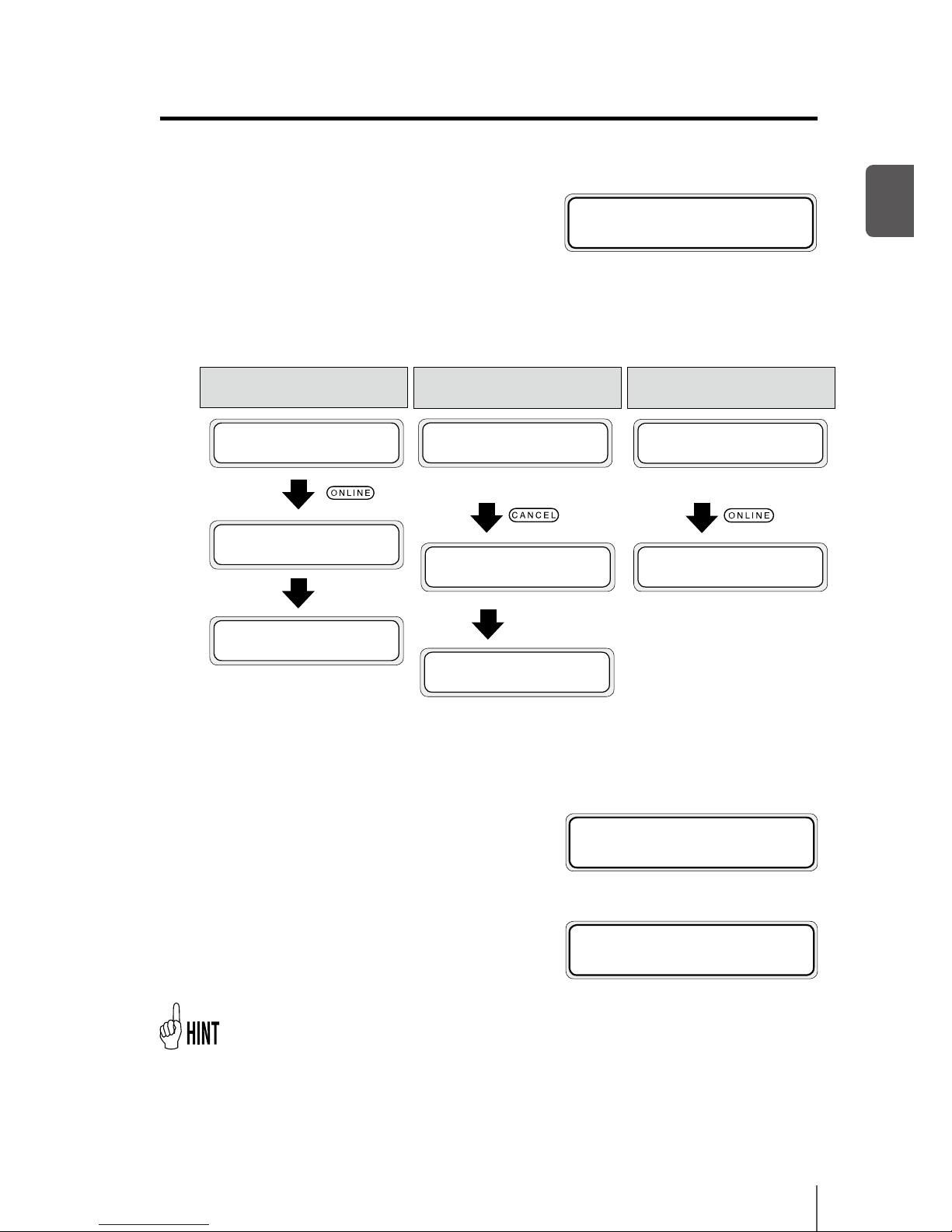
This section explains how to read the LCD display and the state of the printer.
How to read LCD
(1) Initialization display
Shows the initialization of the printer when
the start-up is being processed.
- When the printer starts up normally, it
automatically enters the idle online mode.
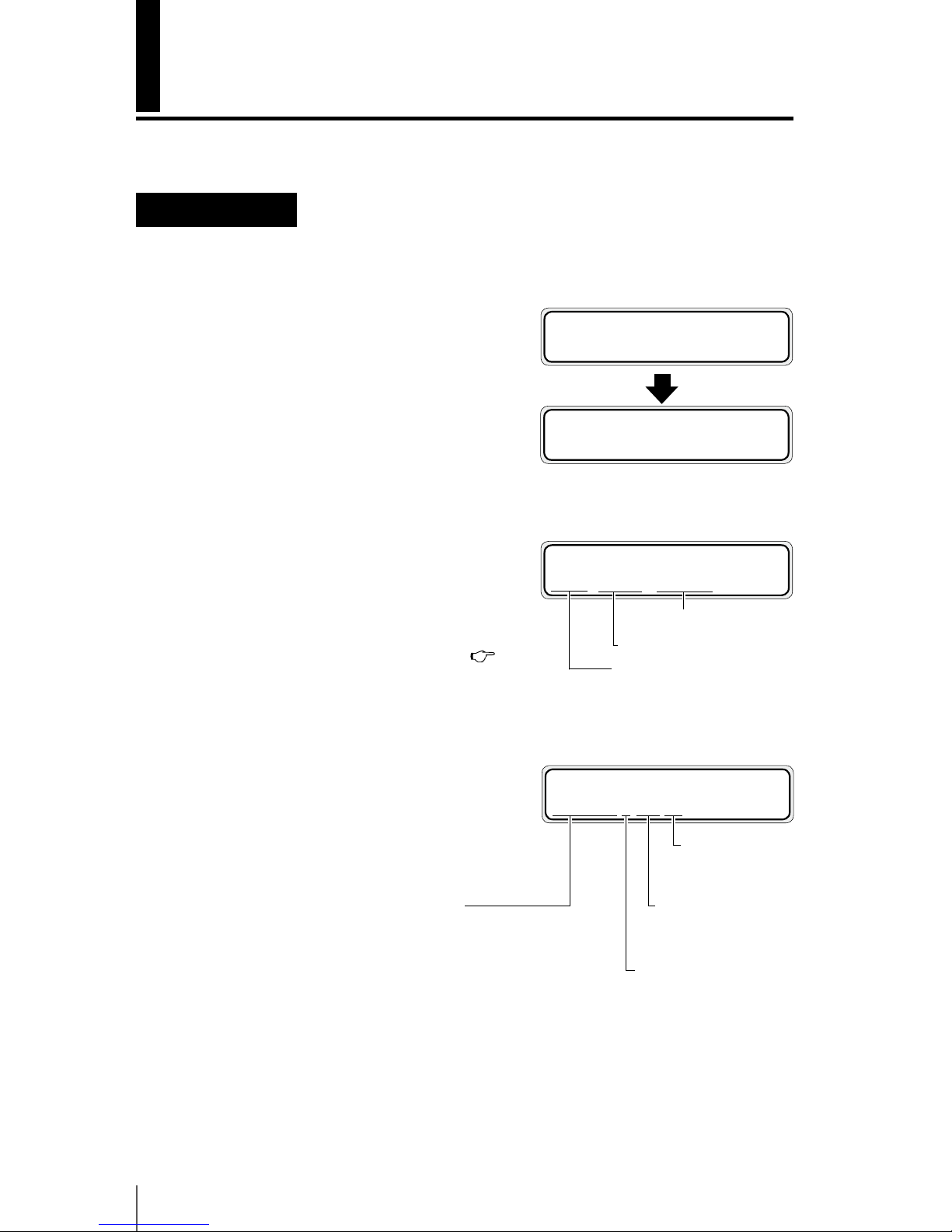
Booting up…
INITIALIZING...
PLEASE WAIT
PRINTER READY
ROLL : 1625 / PAPER
Media name : PAPER
Media of 1625mm (64") width
In case of the set roll media
PRINTING
NORMAL L ND BI
Print direction
BI: Bidirectional
UNI: Unidirectional
Density
ND: Normal density
HD: High density
Smart pass
L: Low
M: Medium
H: High
Print mode
HI-SPD: High print speed
NORMAL: Normal use
HI-QUA: High print quality
MAX-QUA: Maximum print quality
Page 45
Overview
1-21
1
(6) Online state (preheating)
This message indicates that the heater
is in heating process to reach the preset
temperature.
(7) Online state (during head warming-up)
This message indicates that the heads are
warming up.
- Head warming-up is conducted when the head temperature is low.
(5) Online state (print pause mode) display
Shows an interrupted state during printing.
The online LED blinks.
When pausing during printing
PRINTER PAUSING
PLEASE WAIT
PRINTING
NORMAL L ND BI
The online LED blinks.
PRINTER PAUSED
ROLL : 1625 / PAPER
PRINTER READY
ROLL : 1625 / PAPER
- By pressing the PH RECOVERY key during pause (in the state of online LED blinking),
cleaning of the print heads can be executed.
When canceling printing during pause
PRINTER PAUSED
ROLL : 1625 / PAPER
CANCELING
PLEASE WAIT
The online LED blinks.
PRINTER PAUSED
ROLL : 1625 / PAPER
PRINTING
NORMAL L ND BI
The online LED lights.
When resuming printing after paused
PREHEATING
NORMAL L ND BI
PH WARMING UP
NORMAL L ND BI
(4) Online state (waiting for print) display
Shows that print heads are waiting for
printing, data transfer or warm up instruction.
RESTING
NORMAL L ND BI
Page 46
1-22
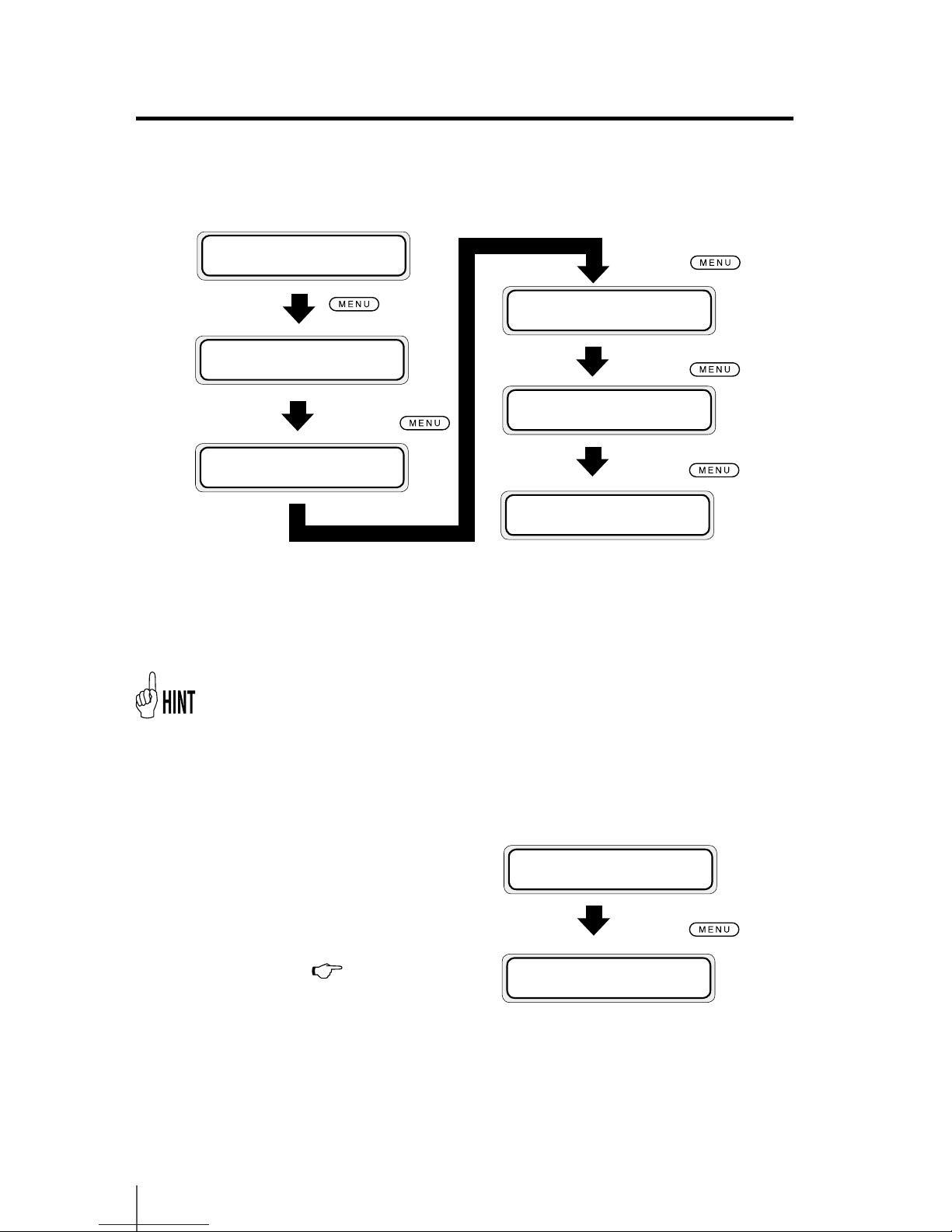
(8) Online state (print information mode) display
Shows the media used, remaining ink, and remaining media.
The display next returns to the online state.
Every 3 second
interval or
PRINTER READY
ROLL : 1625 / PAPER
MEDIA USED:
XXXXXXm
Y INK LEVELXXX%
M INK LEVELXXX%
Lm INK LEVELXXX%
Lc INK LEVELXXX%
Every 3 second
interval or
Every 3 second
interval or
C INK LEVELXXX%
K INK LEVELXXX%
Every 3 second
interval or
REMAINING MEDIA
xxxm
- [YY INK LEVELLOW] is displayed when the remaining ink becomes low.
When the daily maintenance is not performed or the life and replacement time of
consumable parts approaches, the following messages appear.
The display next returns to the online state.
Every 3 second
interval or
PERFORM DAILY
MAINTENANCE NOW
REPLACE
WIPER BLADE
When the daily maintenance
is not performed as usual
(
P.6-13 [When the warn-
ing message is displayed])
- Remaining ink for Lm and Lc is not displayed for the 4 color printer.
Page 47
Overview
1-23
1
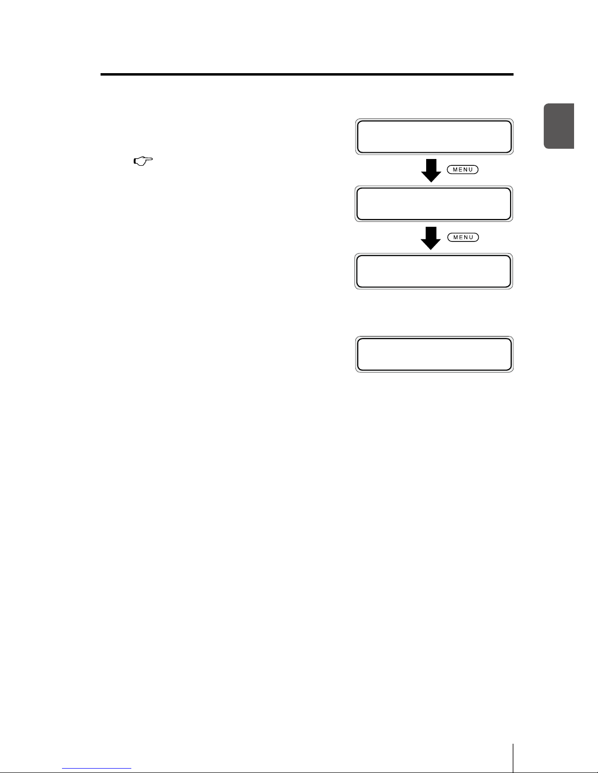
(10) Shutdown state display
This message indicates that the shutdown
process of the printer is being executed.
(9) Oine state (menu mode) display
Shows that the menu operations are available
in the oine state.
(
P.3-2 [Basic menu operation in oine
mode])
- denotes the access key to each menu.
SHUTTING DOWN
PLEASE WAIT
h
INK MEDIA REG
i
f
MEDIA M.ADV
g
h
PRINTER SETUP
i
f
ADJUST HEATER
g
h
REWIND FORM FEED
i
f
PH.REC PH.MAIN
g
LCD display and state of printer
Page 48

1-24
Page 49

Basic operation
This section describes the basic operation of the printer,
such as turning the printer on and o and media replacement.
Connection to a computer .............................................2-2
Power ON / OFF procedure ............................................. 2-3
Media replacement ........................................................... 2-7
How to use the media edge guards ..........................2-19
How to switch the pressure ..........................................2-20
Feeding the media [Feed] .............................................2-21
Rewind the media [Back Feed] ....................................2-22
How to use the origin setting function ....................2-23
Changing temperature using the heater control menu
.... 2-25
Change the Print head height .....................................2-28
Ink cartridge replacement ............................................2-30
Reloadable cartridge replacement ............................2-32
Waste ink bottle replacement .....................................2-40
The media was skewed. .................................................2-43
(Content of this section)
2
Page 50
2-2
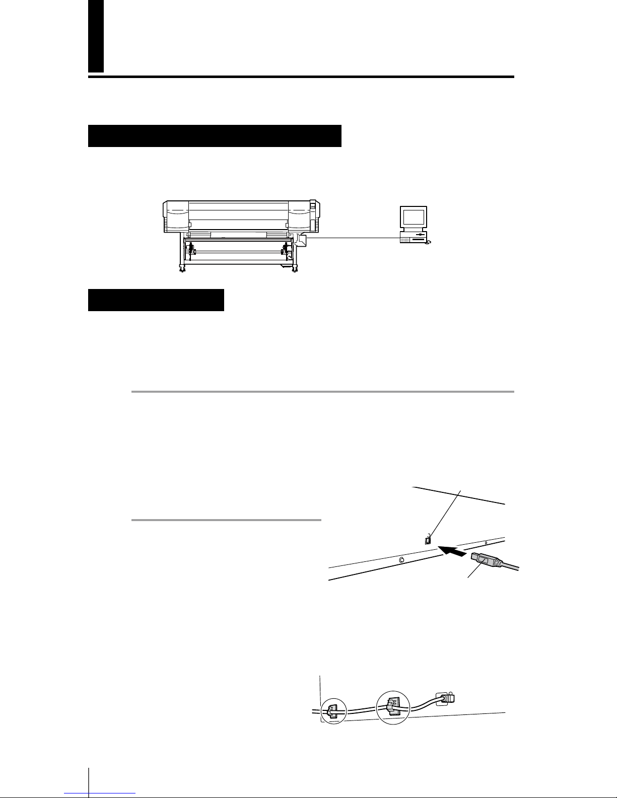
USB connector
Connection to a computer
This section describes the procedure to connect the printer to a computer.
System conguration (Connection example)
See below.
Connecting procedure
Connect the cable following the procedure below.
1
Turn o the power of the printer and computer to be connected.
Note
- When the printer and a computer are connected, turn on the power of the printer
rst and turn o the power of printer last when powering them down.
2
Connect the specic cable to the USB connector at the rear of the printer.
Printer
Computer
USB interface
USB 2.0 cable (B type connector)
Note
- Use a USB 2.0 cable.
- When using a USB hub, use a product
that supports UBS 2.0.
- For the cable and hub used for USB
connection to the system, use USB-IF approved products. When connecting the
non-approved USB cable, hub and equipment, the printer may not function
properly.
- The maximum length of one cable is 5 m. If you desire to extend longer than 5 m,
use a hub. The maximum length conguration is 5 stage hub connection. If a cable
longer than 5 m is used or if the cables are merely connected, the printer may not
function properly.
- To protect the USB connector, clamp
the USB 2.0 cable to the printer
body.
Page 51

2-3
2
Basic Operation
Power ON / OFF procedure
Use the power switch on the operation panel of the printer to turn the power on
or o.
Note
- When the printer and a computer are connected, turn on the power of the printer
rst and turn o the power of the printer last when powering them down.
Page 52
2-4
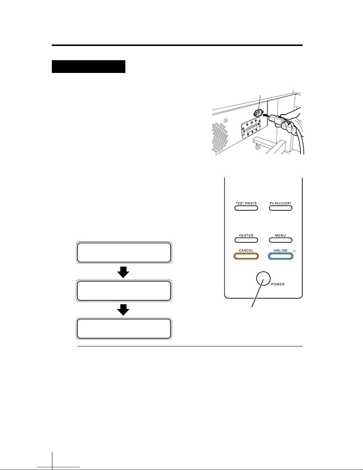
Power-on procedure
1
Connect the supplied power cable to the
power inlet of the printer and AC power
supply outlet.
2
Turn on the power switch on the operation
panel.
When turning on the power, the printer
performs the power-on self-diagnostic test
and displays the following messages on the
operation panel.
Note
- When the printer is performing “INITIALIZING...”or “CLEANING”, if the power is
turned o unnecessarily, ink may drip or the print head may be damaged.
Power switch
Power inlet
Example of the set roll media of 1625 (mm)
PRINTER READY
ROLL : 1625 / PAPER
INITIALIZING...
PLEASE WAIT
Booting up…
Page 53

2-5
2
Basic Operation
Note
- Do not use a power cable other than the supplied power cable for the printer.
- Conrm that the supplied power cable meets the requirements of AC power in
your local area.
- If the LED on the operation panel does not light when the power switch on the operation panel is turn on, the power supply is defective.
- When a problem is detected in the power-on self-diagnostic test, an error message is
displayed on the LCD. Refer to [Section 6 Troubleshooting], for more information.
q Power ON / OFF procedure
Page 54

2-6
Power-o procedure
1
To turn o the power of the printer,
keep pressing the power switch on the
operation panel for 2 seconds.
The message shown above is displayed on the LCD to show that the shutdown
process is being executed. The power is o after the shutdown is nished.
To keep the print head in good condition during shutdown, the ll cap operation
(state that the cap is lled with ink) is performed. To quickly turn o the power,
press the power switch while holding the
key to skip the ll cap operation and turn o the power. However, generally executing the ll cap operation is
recommended.
Note
- After turning the power o, wait at least 5 seconds before turning it back on.
- To keep the print heads in good condition, the printer perform automatically and
periodically the ll cap operation while in standby mode. It is recommended to
keep on the power switch on the operation panel.
SHUTTING DOWN
PLEASE WAIT
Page 55
2-7
2
Basic Operation
Roll media installation procedure
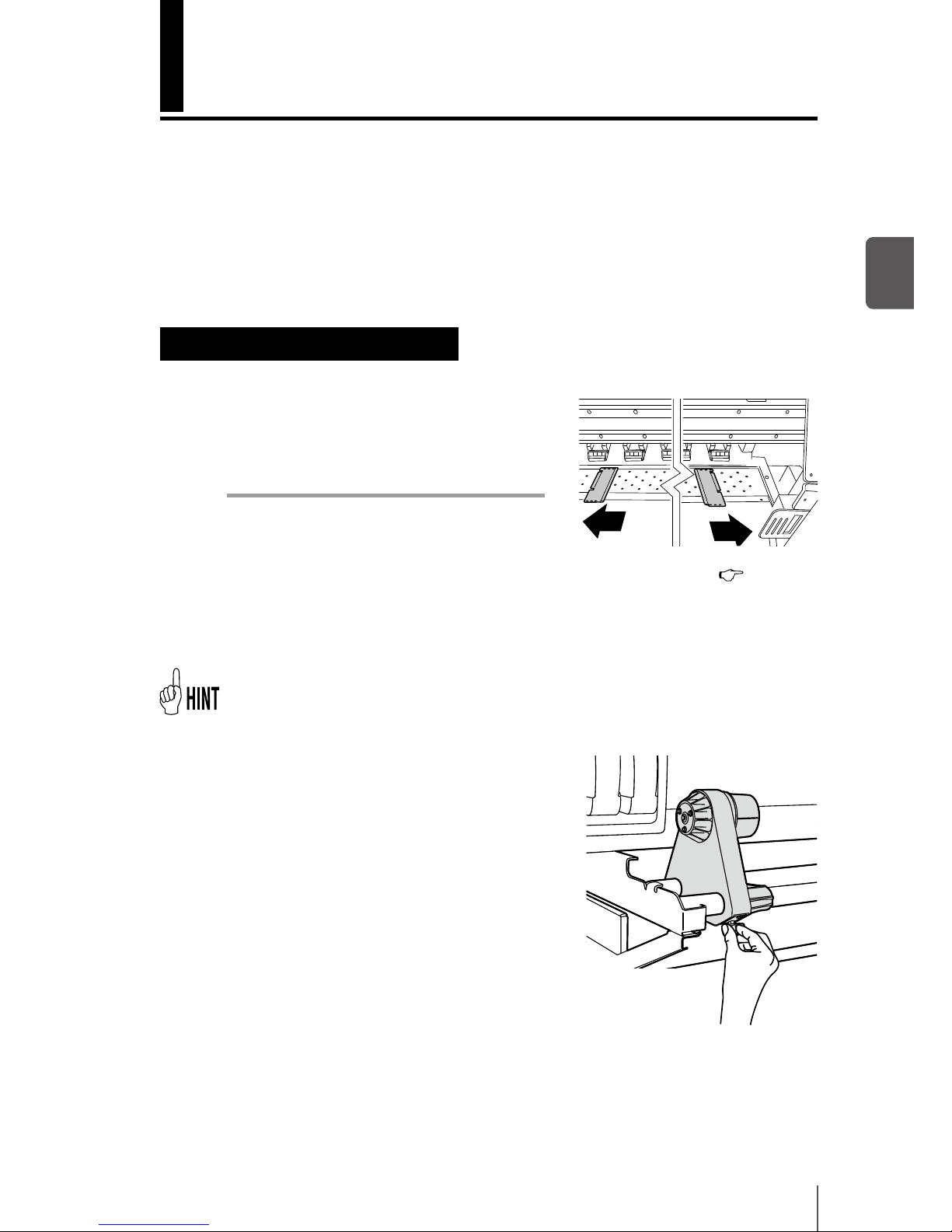
1
Open the front cover and slide the media
edge guards to each end of the platen.
Then, close the front cover.
Note
- Move the media edge guards to both ends
so they cannot enter under the media.
- After completing the media replacement work, set the media guards. (
P.2-19
[How to use the media edge guard])
- When using media with adhesive applied to the core at the end of the roll, this
adhesive may stick to the paper guide or the platen. In this case, always clean up
the adhesive before using the media.
If a blower unit is used, move it to a place where it will not disturb the operation.
2
Put the left side media holder in position and
x it temporarily by turning the screw.
Media replacement
This section describes the roll media installation / removal procedure. The
two situations below require roll media replacement:- When the roll media is
nished, the roll media is replaced.
- When the roll media is jammed, the roll media is replaced.
The roll media replacement procedure for each case is shown below.
Page 56
2-8
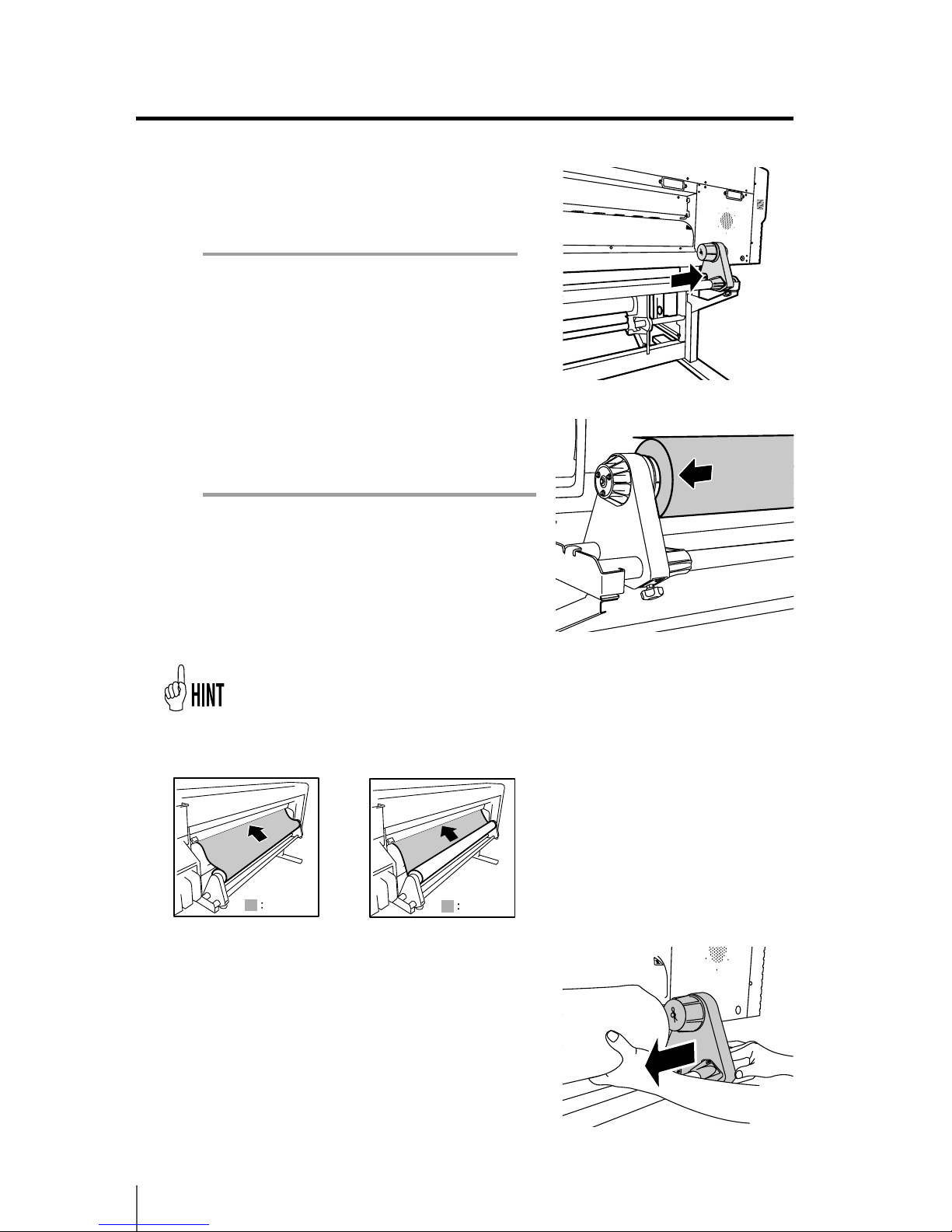
3
Move the right side media holder to the
right end.
Note
- When using media with adhesive applied to
the core at the end of the roll, this adhesive
may stick to the paper guide or the platen.
In this case, always clean up the adhesive.
4
Set the roll media to the media holder xed
on the left side.
Note
- When inserting the roll media in the media
holder, be careful not to cause the media to
shift on the roll or damage the end surface of
roll media.
- Make sure that the core is securely xed to the
roll holder by inserting it completely.
5
Set the roll media to the right side media
holder.
<In case of roll media with
print side outside>
Print side
Print side
<In case of roll media with
print side inside>
Media setting direction
Page 57
2-9
2
Basic Operation
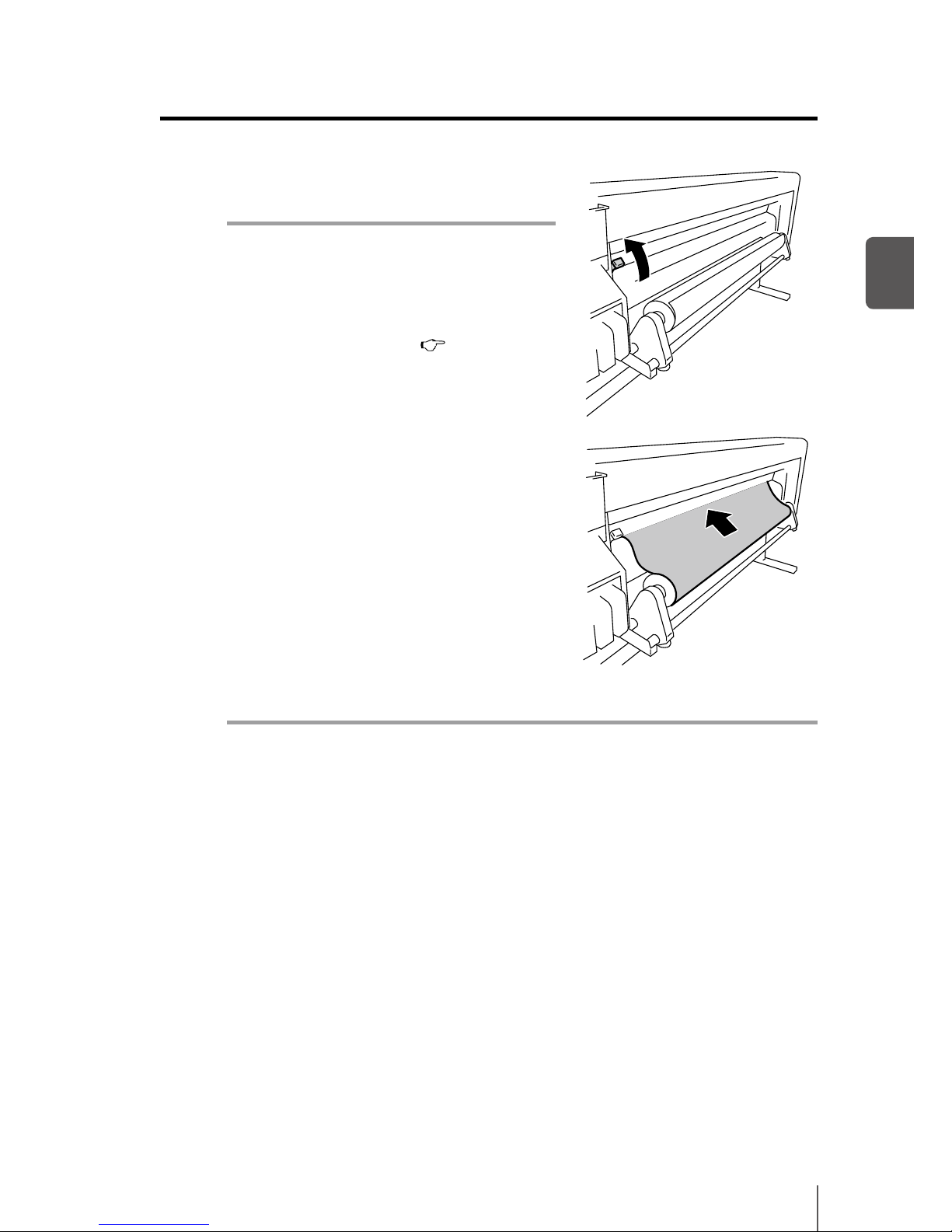
6
Raise the pressure roller up / down lever.
Note
- There are three selectable positions (up,
middle and down) on the pressure roller up
/ down lever. To raise (release) the pressure
roller here, raise the pressure roller up / down
lever to the top position. (
P.2-20 ([How to
switch the pressure])
7
Feed the media between the pressure roller
and grit roller and advance the media until
the leading edge of the media comes out of
the front cover.
Advance the media until the leading edge
of the media comes out at a distance of 200
mm.
When the leading edge of the media comes
out of the front cover, a conrmation beep sounds.
Note
- Depending on the environment, the media may stick to the paper guide and may
be hard to advance. In this case, advance the media while raising it from the paper
guide by holding both edges with hands.
- If the leading edge of a media is curled up or curled down, the media may be
caught in the printer or may not be properly set. If the media is curled too much,
do not use it.
- Be careful that the leading edge of the media does not touch the front cover. If the
roll media tends to roll, stretch it to eliminate the rolling before loading.
- Check that the media edge guard does not enter under the media.
q Media replacement
Page 58
2-10
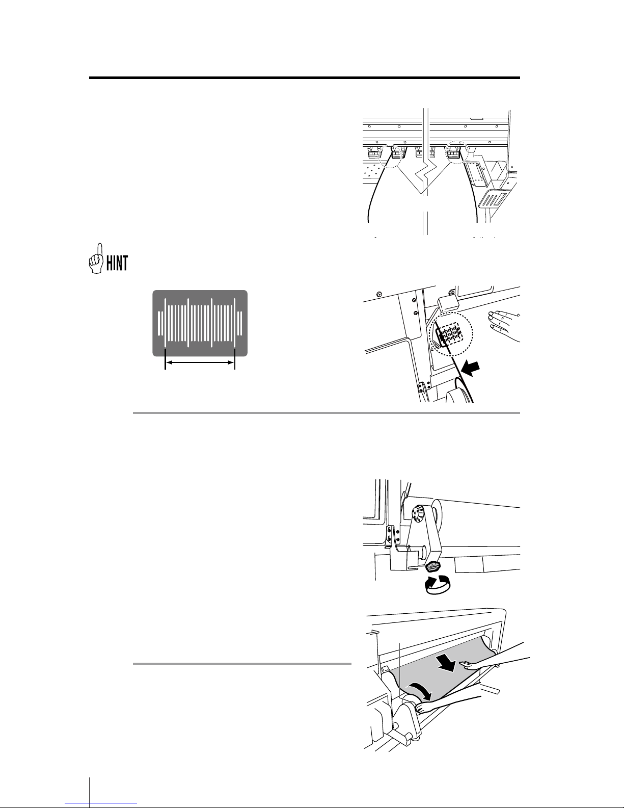
8
Move the media holders so that the both
edges of the media are equally distributed
on the pressure roller.
- Noting the relationship between the label gradation (indication line) and the media
width will let you easily adjust the position next time you will set the media.
Note
- If you shift the media only, skewing will occur. Adjust the load position by moving
the media and the media holders together.
9
Secure the positions of the right and left
media holders by turning the screws.
10
Hold the center of media with your hand
and turn back the ange to eliminate the
slack.
Note
- Do not forcibly align the edge of media to the
indication line. Set the media straight with
regard to the roll.
Set so that the end surface of the
media comes within this range.
Load the media so that the media is
evenly applied to the pressure roller.
Flange
Page 59
2-11
2
Basic Operation
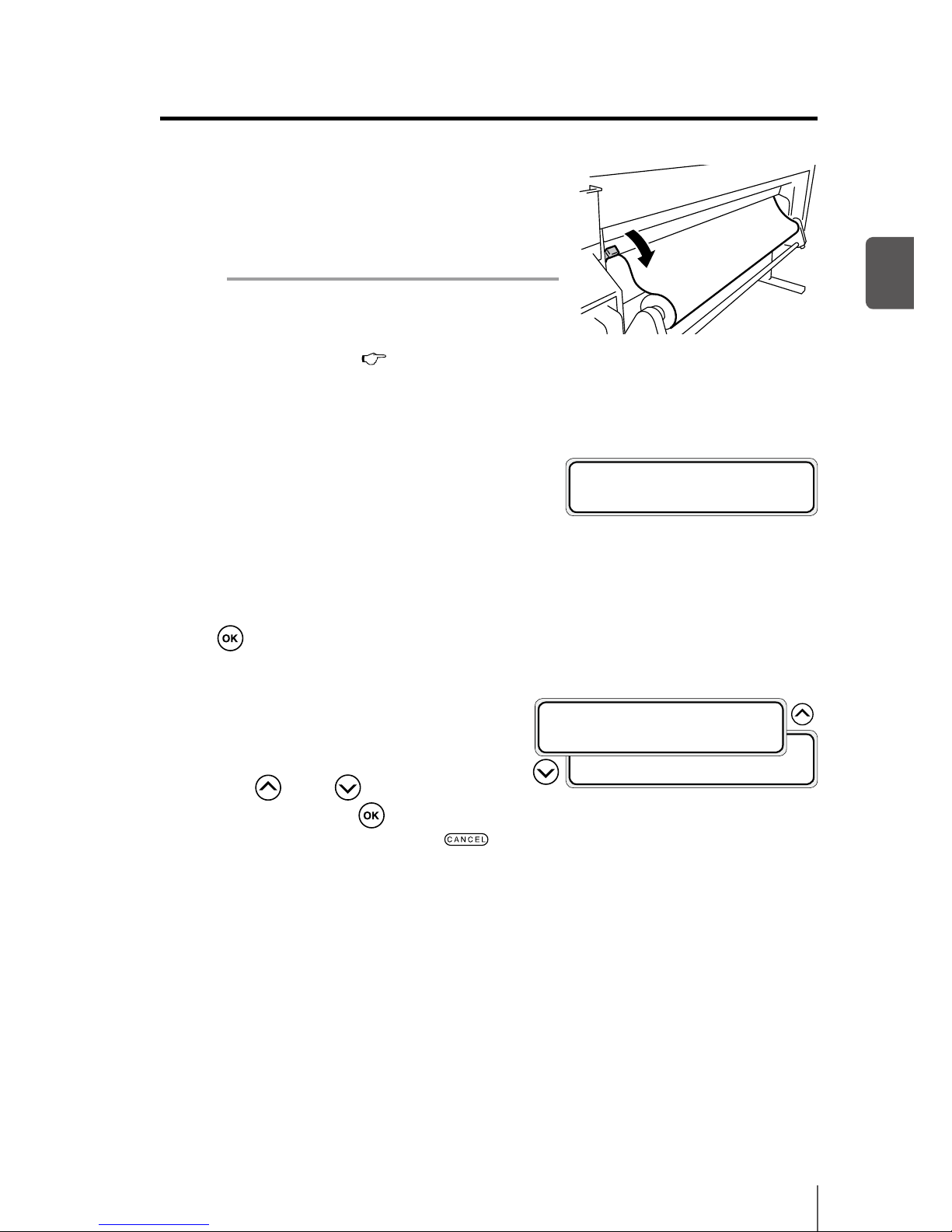
11
Lower the pressure roller up / down lever.
After this, follow the instructions on LCD
screen.
Note
- To lower (press) the pressure roller, lower
the pressure roller up / down lever to the
lowest position. (
P.2-20 [How to switch the
pressure])
12
Open the front cover and align the media
edge guards over the both ends of the
media. Then, close the front cover.
Check that the media edge guards do not go under the media and that thick
media is not stuck between them.
After visually conrming that the media edge guards are properly set, press the
key.
13
Select either the roll media or the cut
media (sheet).
Either [roll] or [sheet] can be selected
with
key or key. Here, select
[roll] and press the
key. (To return to
the media selection, press the
key.)
SELECT MEDIA
ROLL/SHEET:SHEET
SELECT MEDIA
ROLL/SHEET:ROLL
CHECK EDGE GUARD
*OK ?
q Media replacement
Page 60
2-12
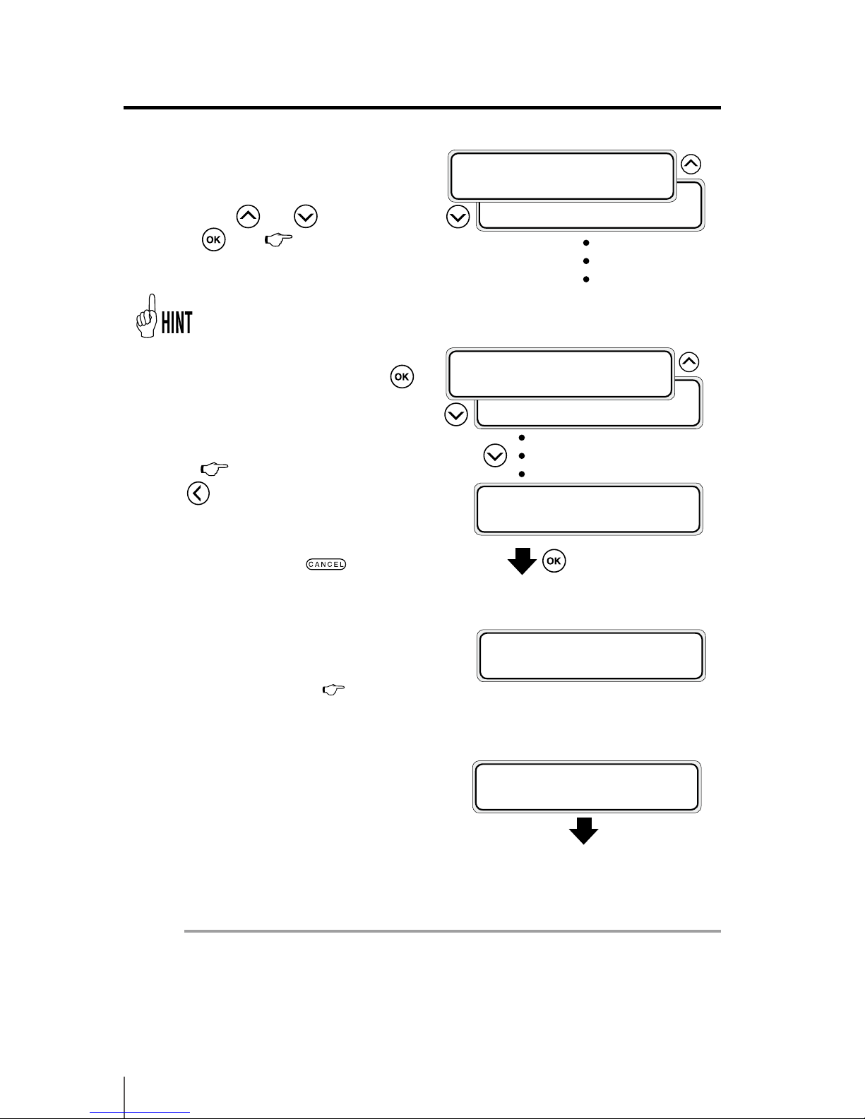
15
Enter the remaining length of media.
Enter the remaining length of roll media
loaded to the printer.(
P.3-18 [MEDIA
MENU])
16
The media set operation automatically
starts.
- When successfully nished, the printer returns to the online state or oine state.
- If an error occurs, an error message is displayed. Go back to step
1
and start
the procedure again.
Note
- After installing the media, check that the media does not enter in the gap of the
media cutter blade or is not pinched by the media clip. Also make sure the media
on the platen has no curl or wrinkles.
To register a new media
14
Select the type of media.
Select the type of media registered
with the
and keys and press
the
key. ( P.3-20 [MEDIA
REG MENU])
REMAINING MEDIA
*XXXm
PREPARING MEDIA
PLEASE WAIT
[NEW MEDIA ENTRY] is displayed at the
end of media registration. Press the
key to enter [MEDIA REG MENU]. The
media registration procedure is the same
as the registration from the registration
menu. (
P.3-20 [MEDIA REG MENU])
Press
key to return from the media
registration menu to the media type
selection menu. To return to the value
before input, press the key.
SELECT MEDIA
MEDIA:XXX
SELECT MEDIA
MEDIA:PAPER
SELECT MEDIA
NEW MEDIA ENTRY
The registered media is displayed.
(Enter in the registration
menu.)
SELECT MEDIA
MEDIA:XXX
SELECT MEDIA
MEDIA:PAPER
Page 61
2-13
2
Basic Operation
Note
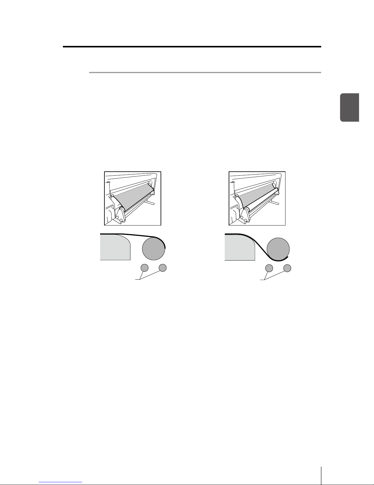
- With tarpaulin and other high basis weight media, limit the media slack on the
media roll side to 15 cm. The weight of the loose media may unwind the roll media.
- When rewinding more than 30 cm of the media, do not rewind it at once but
execute the operation slowly while eliminating the slack by rotating the media by
hand.
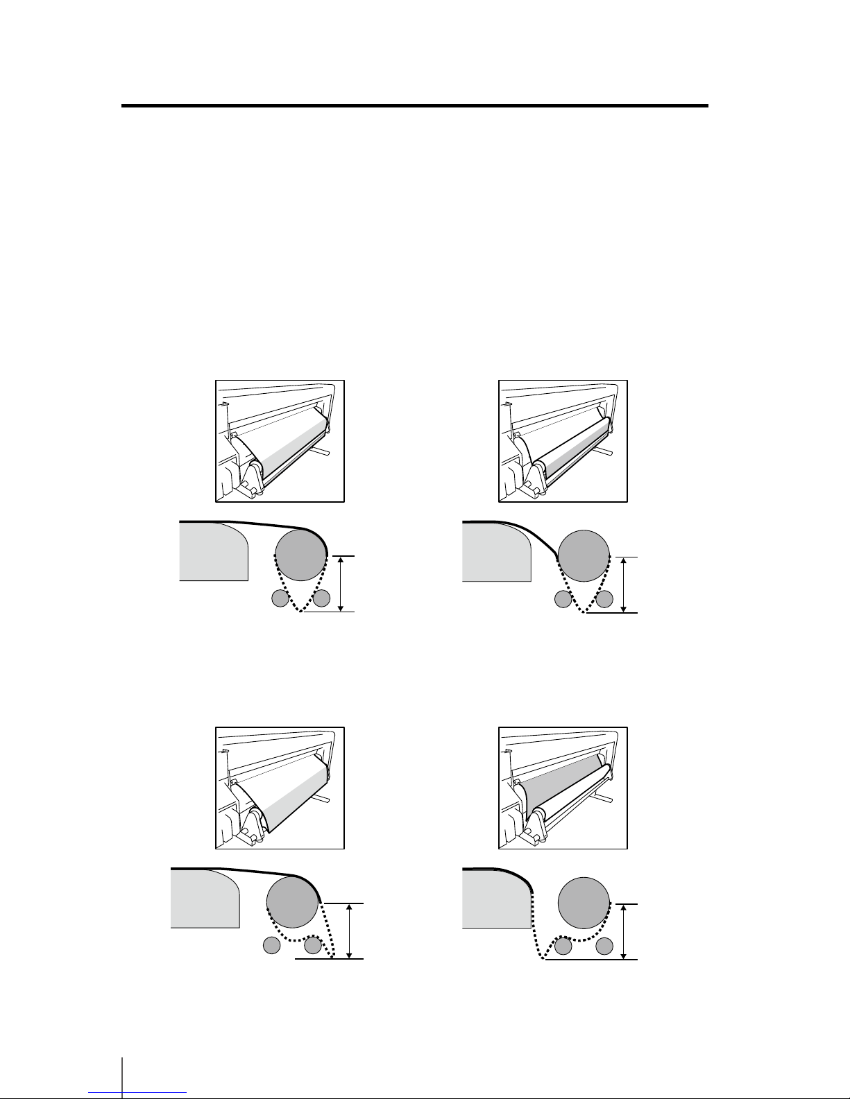
<Correct installation>
Make sure that the media is stretched tight as shown in the gure below.
<In case of roll media with print side outside> <In case of roll media with print side inside>
Rear paper guide
Feeding pipes
Roll media
Rear paper guide
Feeding pipes
Roll media
q Media replacement
Page 62
2-14
<Incorrect installation>
Eliminate the slack so that the media does not become like in the two examples
below.
The gures on the upper parts are perspective views of the printer rear side. The
gures on the lower parts are sectional views of the paper feed mechanism.
The slack is in gray in the perspective views and in dashed line in the sectional views.
Example 1
Example 2
<In case of roll media with print side outside>
<In case of roll media with print side outside>
<In case of roll media with print side inside>
<In case of roll media with print side inside>
Slack within
15 cm
Slack within
15 cm
Slack within
15 cm
Slack within
15 cm
Page 63
2-15
2
Basic Operation
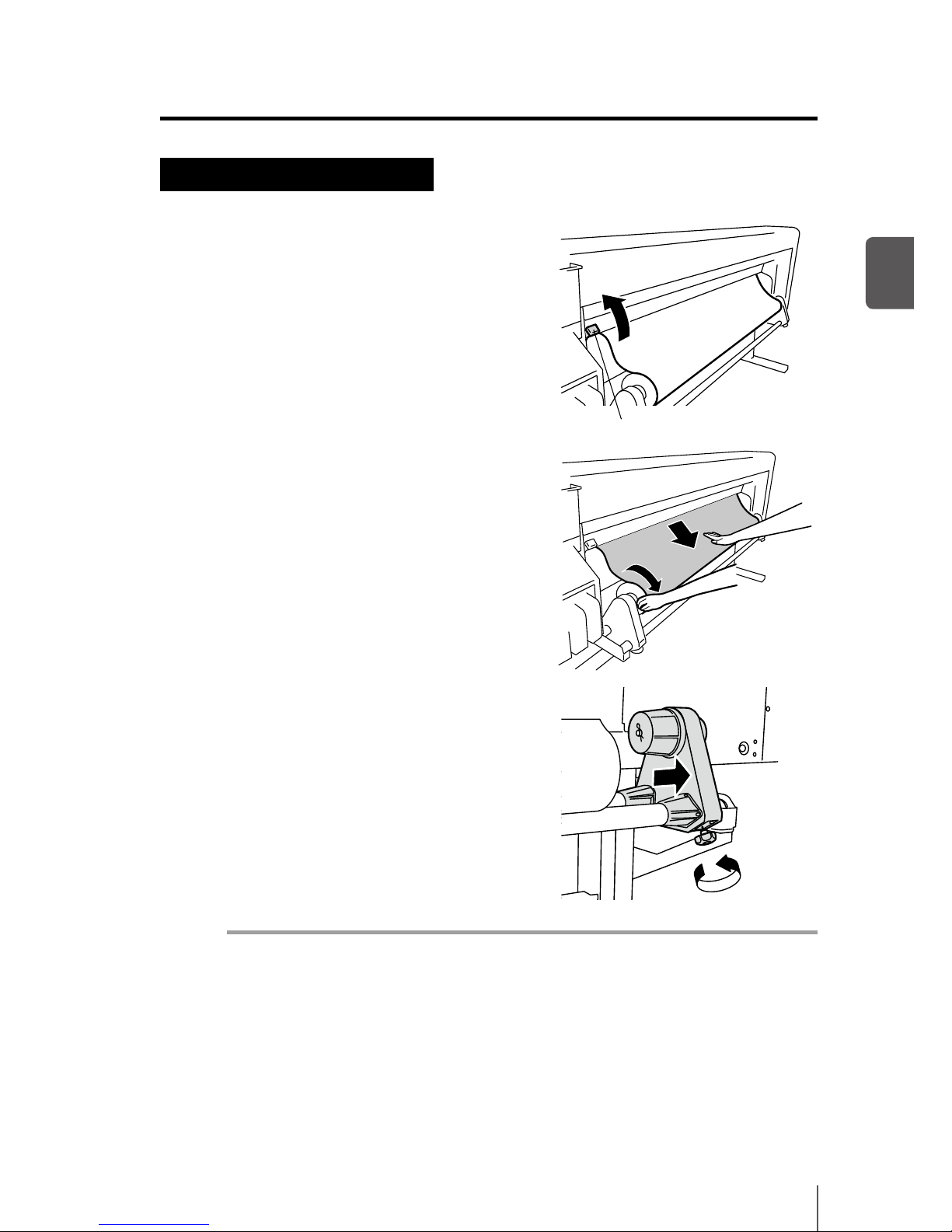
Roll media removal procedure
1
Raise the pressure roller up / down lever.
2
Rewind the ange to roll back the media.
3
Loosen the screw of the media holder to
the right, and while moving this media
holder slightly to the right, remove the
roll media from the media holder.
Note
- When removing the roll media from the media holder, be careful no to let it fall as
it may lead to personal injuries.
Pressure roller up / down lever
q Media replacement
Page 64
2-16
When replacing the roll media after it runs out
When the printer runs out of media, the printer automatically detects the end and
displays a message. Depending on the media’s nishing (media glued to core), the
printer may not automatically detect it. If printing continues in this condition, the
printer may be stained or damaged. Visually check the remaining media.
1
The message appears on the LCD
screen.
2
Replace the media according to the media installation and media removal
procedures.
When replacing the roll media due to jamming
Refer to [Section 6 Troubleshooting (How to clear media jams) ].
NO MEDIA LOADED
LOAD MEDIA
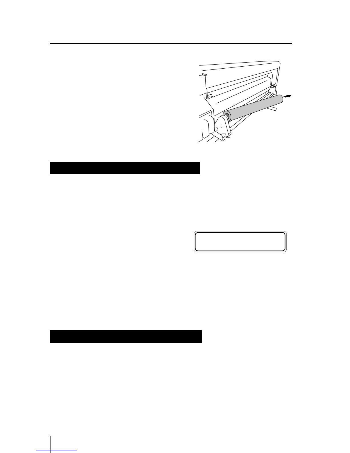
4
Pull the roll media out of the left media
holder and remove the roll media.
Page 65
2-17
2
Basic Operation
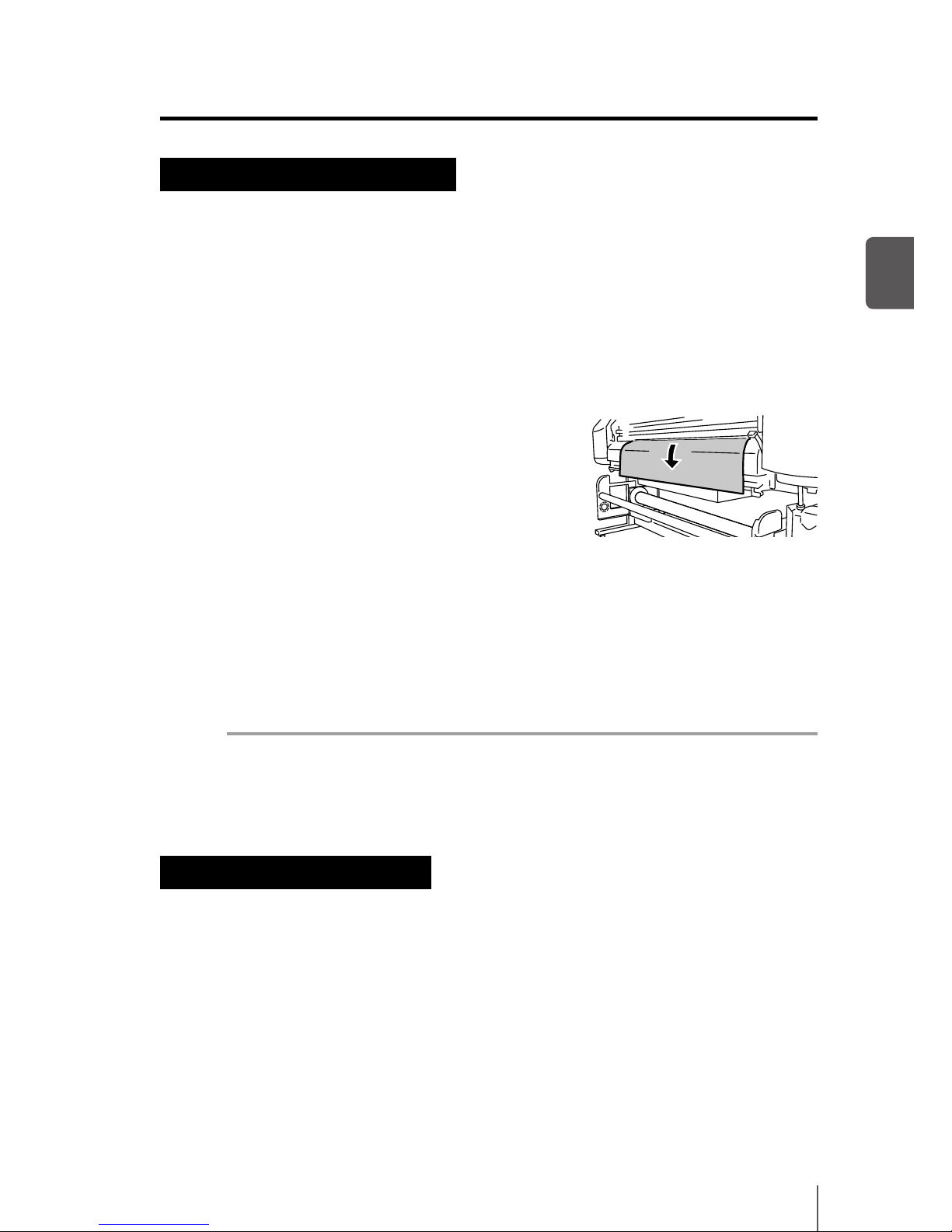
Cut media installation procedure
1
Open the front cover and slide the media edge guards to each end of the
platen. Then, close the front cover.
2
Raise the pressure roller up / down lever.
3
Advance the media until the leading edge of
the media comes out of the front cover.
4
Move the media so that both ends of media
are evenly applied to the pressure roller.
5
Lower the pressure roller up / down lever.
After this, follow the instructions on LCD screen.
Note
- Select [SHEET] for [SELECT MEDIA].
- When selecting [SHEET], the remaining media cannot be entered.
Cut media removal procedure
1 Raise the pressure roller up / down lever and remove the media.
q Media replacement
Page 66
2-18
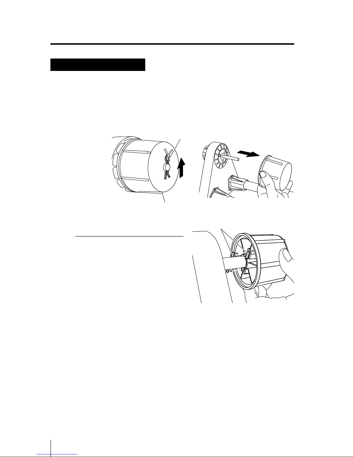
When using 2 inch core rolls
2 inch core rolls can be used when the 2 inch ange option is installed. This section describe the procedure to install the 2 inch ange.
1
Remove the R pin from the 3 inch ange, then remove the ange.
2
Install the 2 inch ange
Note
- Make sure that the pins match the
grooves.
- A new ange may be hard to insert.
Make sure to insert it all the way in.
- Be careful not to lose the R pin and the
pins.
3
Replace the R pin.
Pin
R pin
Page 67
2-19
2
Basic Operation
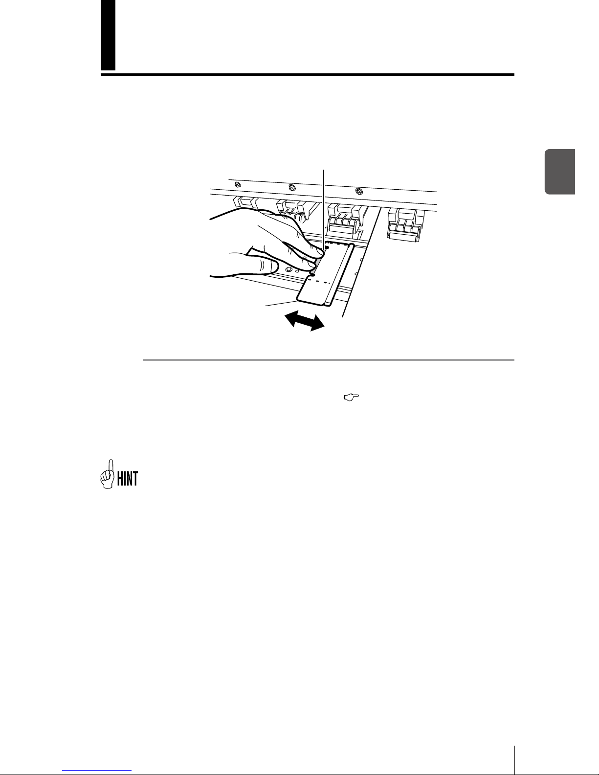
Press this part to set it easily.
How to use the media edge guards
Using the media edge guards protect the print heads from media edges’ curls.
Slide the edges of the guards over the edges of the media.
Note
- Set “use / not-use” for media edge guard in the MEDIA REG MENU. The widths of
right and left margins of the media change. (
P.3-29 [(8) EDGE GUARD])
- Clean the media edge guards when they get dirty.
- The media edge guards will not prevent curl eects from all media. As it causes
print defects, eliminate waves and folds beforehand.
- The media edge guards cannot be used with thick media. Do not insert it forcibly.
- The right and left margins of the print area become 10 mm when using the media edge
guards.
Media edge guard
Media
Page 68
2-20
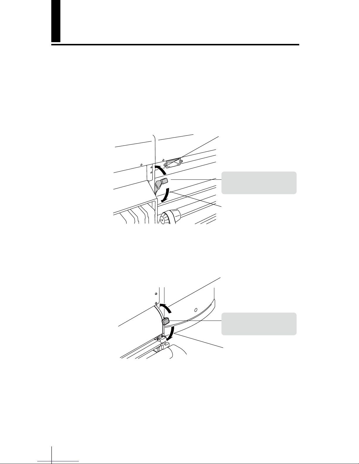
How to switch the pressure
Switch over the pressure between the pressure roller and the grit roller used for
media feeding to match dierent media. The bottom position is normally used.
When skew occurs in the media and the media cannot be fed or when using a
media with weak elasticity such as a thin cloth, switch to [weak], the center position. The pressure force is switched using the pressure roller up / down lever. (See
gure below.)
<No pressure> (top)
When loading the media, raise
the lever. This the normal UP
position.
[Rear]
[Front]
<Normal Pressure> (bottom)
When the media is loaded,
lower the lever.
It is the normal DOWN position.
<Weak> (in the center)
The pressure becomes weak.
<No pressure> (top)
When loading the media, raise
the lever. This the normal UP
position.
<Normal Pressure> (bottom)
When the media is loaded,
lower the lever.
It is the normal DOWN position.
<Weak> (in the center)
The pressure becomes weak.
Page 69
2-21
2
Basic Operation
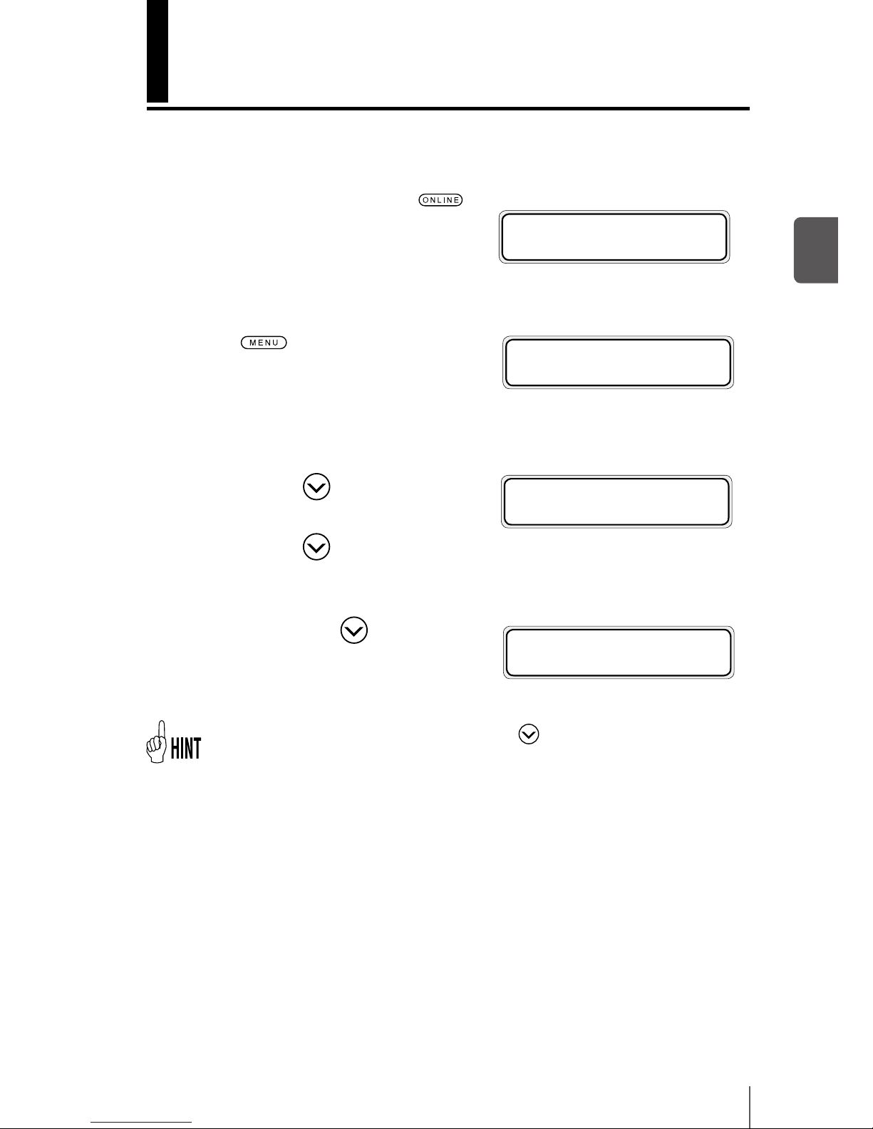
Feeding the media [Feed]
This function feeds the media.
1
Set the printer to oine.(Press key.)
2
Press key to move the menu
group to the second layer menu and to
display the FORM FEED MENU.
3
Keep pressing key.
While pressing
key, the roll media is
fed. When cut sheet media is used, the paper is ejected.
4
When releasing the key, feeding
stops and the printer returns to the
oine state (menu mode).
- When the online state (idle mode) is displayed, if key is pressed, the media can be
fed without entering the FORM FEED MENU.
h INK MEDIA REGi
f MEDIA M.ADVg
h REWIND FORM FEEDi
f PH.REC PH.MAINg
h REWIND FORM FEEDi
f PH.REC PH.MAINg
FEEDING MEDIA
Page 70
2-22
Rewind the media [Back Feed]
This function rewinds the media.
1
Set the printer to oine.
(Press
key.)
2
To display the [REWIND] menu, press
key.
3
Keep pressing key.
While pressing
key, the roll media
is fed back. When the cut media is used,
the paper is ejected.
4
When releasing the key, rewinding
stops and the printer returns to the
oine state (menu mode).
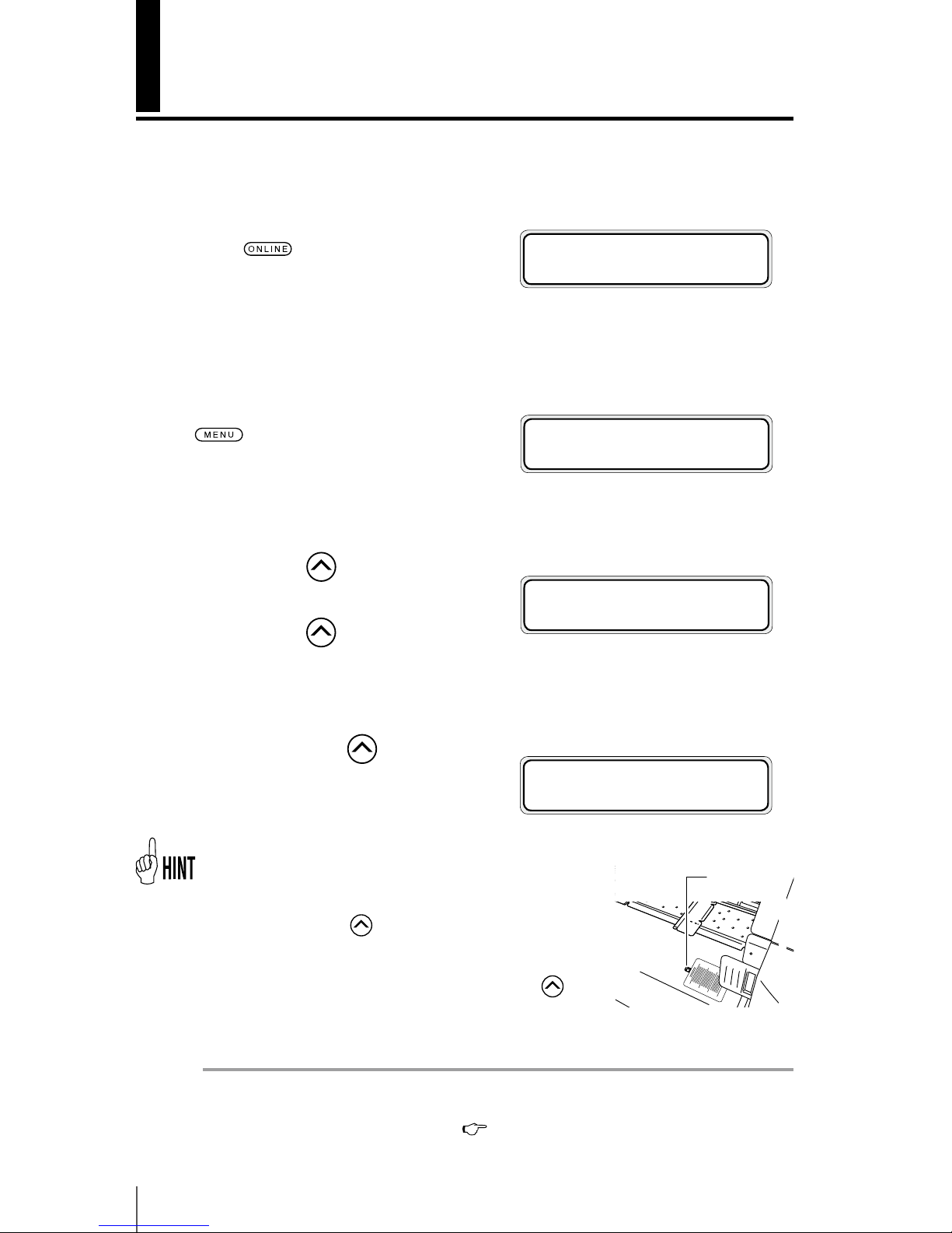
- A paper ejection sensor that detects the media is installed to the front paper guide. If the media covers the
paper ejection sensor, the media can be fed back. When
you keep pressing
key, the media can be fed back at
a maximum distance of 14 cm from the paper ejection
sensor.
- When the online state (idle mode) is displayed, if
key
is pressed, the media can be fed back without entering in
the REWIND MENU.
Note
- When rewinding high basis weight media, the weight of the loose media may
unwind the roll media. (For details,
P.2-13, P.2-14)
h INK MEDIA REGi
f MEDIA M.ADVg
h REWIND FORM FEEDi
f PH.REC PH.MAINg
h REWIND FORM FEEDi
f PH.REC PH.MAINg
REWINDING MEDIA
Paper ejection
sensor
Page 71
2-23
2
Basic Operation
Margin Set the origin
NEST ORIGIN SETTING
*OK ?
How to use the origin setting function
<Origin setting function>
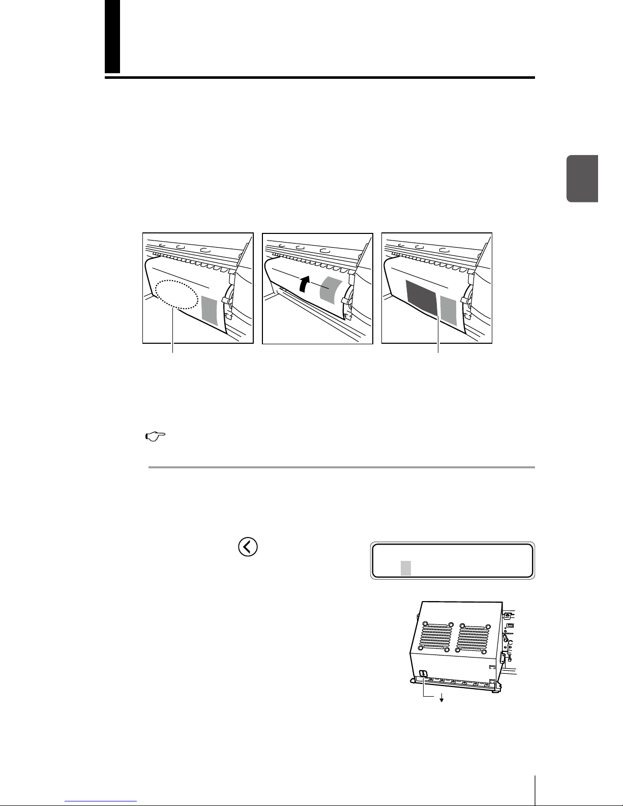
When a small image is printed on, for example, a “64” width media, a large margin
is created as shown below.
By returning the printed media and re-setting the origin of print start, another
image may be printed in this margin. Re-setting the origin of print is called [Origin
setting function].
<Procedure to use the origin setting function>
1
Return the media by operating [Back Feed].
(
P.2-22 Rewind the media [Back Feed])
Note
- Return the media only after the printed image completely dries. The rst printed
image will be damaged if this function is used before it is suciently dry.
2
Press and hold the key for 1.5 seconds
in the online state (idle mode) to move
the carriage and enable the origin setting.
Align the [] label on the carriage front with the
origin.
(First print)
(Return of media)
(Second print)
[ ] Label
Page 72
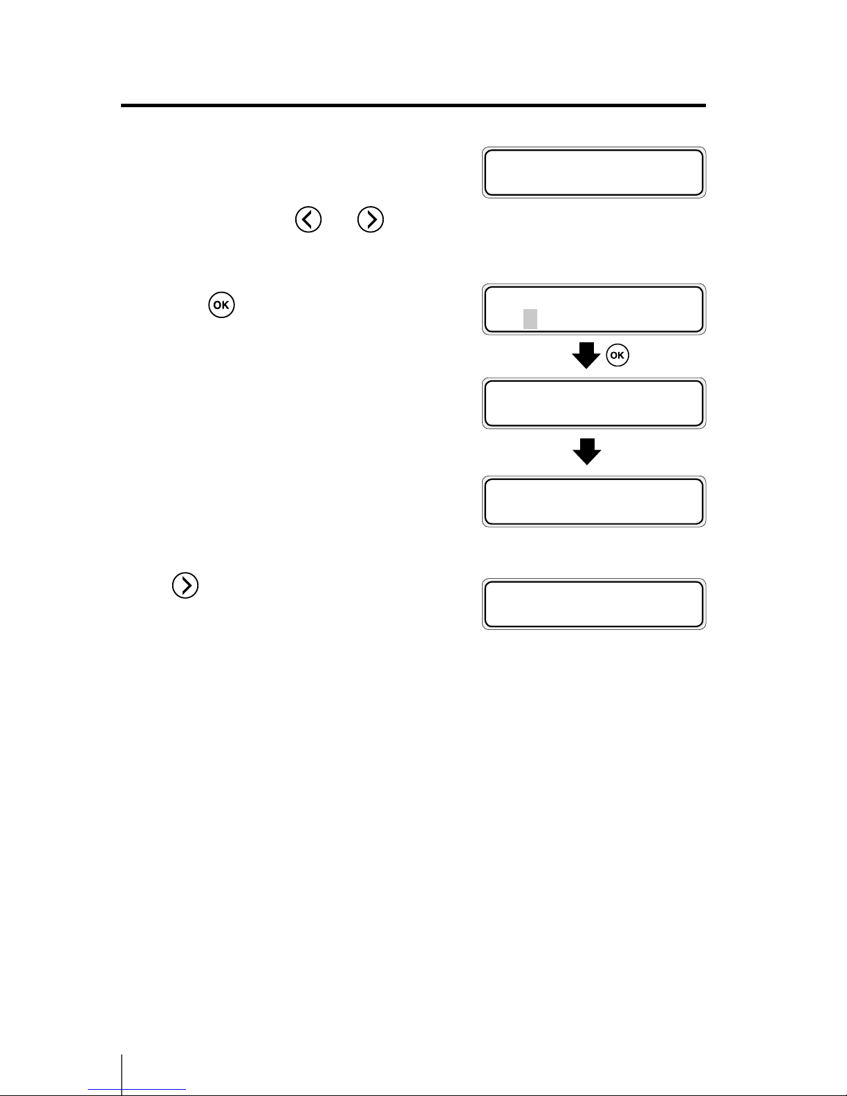
2-24
3
When [NEST ORIGIN SETTING] is displayed,
move the carriage to the desired position
as the origin with
and keys.
4
Press key to conrm the origin setting.
The carriage returns and the printer
becomes ready to print (online state (idle
mode) display).
To cancel the set origin, press and hold the
key for 1.5 seconds in the idle mode,
or raise the pressure roller up / down lever.
When canceled, the display returns from
[NEST] to [ROLL] or [SHEET].
NEST ORIGIN SETTING
CARRIAGE MOVING
NEST ORIGIN SETTING
*OK ?
NEST ORIGIN SETTING
PLEASE WAIT
PRINTER READY
NEST:1625/PAPER
PRINTER READY
ROLL : 1625 / PAPER
<Display when canceled>
Page 73
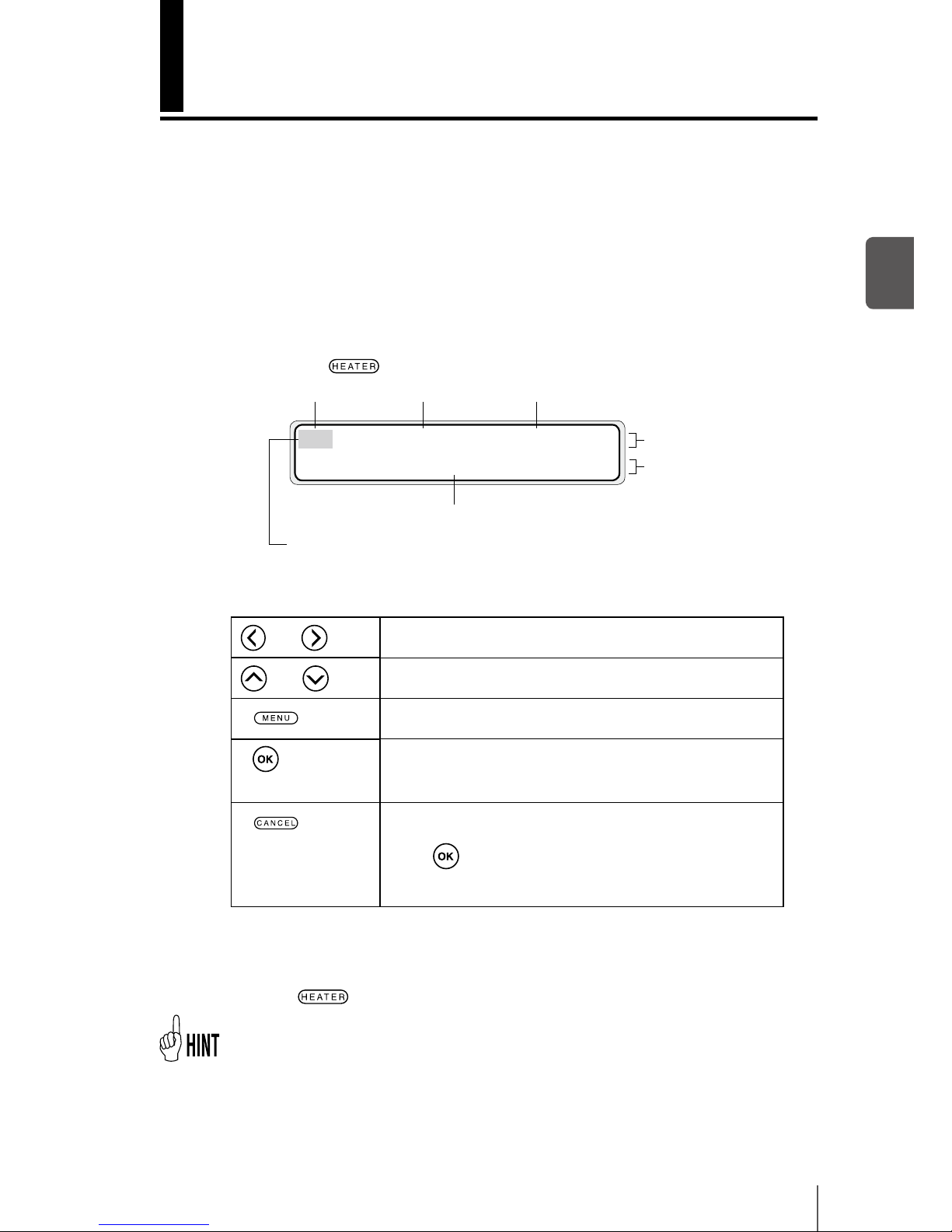
2-25
2
Basic Operation
¢ Key operation in the heater control menu
Changing temperature using the heater control menu
The heater initial value that is set in MEDIA REG MENU is automatically set for the
temperature of each heater. Therefore, the heater control menu is generally not
needed. The heater control menu is used to ne-adjust the heater temperature
during printing or to monitor the current heater temperature.
¢ Heater control menu display
Aft 40 Prn 45 Pre 45
C) 40 C) +40 C) 45
Set temperature
The “+” mark indicates that it is currently heating
After heater Print heater
Currently selected heater
Preheater
Current temperature
-
When no key is pressed for more than 30 seconds with the heater control menu displayed,
[HEATER DISPLAY END] is automatically displayed and the heater control menu display is closed.
- Even if heater temperatures are changed in the heater control menu, the initial temperature value of each heater stored in MEDIA REG MENU remains unchanged.
- When the temperature unit in SETUP MENU is set to Fahrenheit, every temperature is
displayed in Fahrenheit.
¢ To nish displaying the heater control menu
Press the key to display the heater control menu.
and keys
Select a heater for which temperature is to be set.
and keys
Set the heater temperature.
key
Selects heater ON or OFF.
key
When this key is pressed for 1.5 seconds while the heater
control menu is displayed, all the heaters are forcibly activated and left ON even without print operation.
key
Pressing this key for 1.5 seconds with the heater control
menu displayed cancels the heater-on state made forcibly
by the
key. (The heater-on state is canceled and then
the printer returns to the normal control following delay
time and standby time settings.)
Press the key while the heater control menu is displayed.
Page 74
2-26
¢ Reference information on media types and heater settings
The heater set temperatures and reference set values (initial values) of print mode
for each type of media are shown in the table below. Change the settings according to the media in use.
Media type
Media
selection
Recommended heater temperature
setting
Print mode
After heater Print heater Preheater
Glossy vinyl
chloride
Glossy 45ºC 40ºC 45ºC Normal, bidirectional
Matte vinyl
chloride
Matte 45ºC 40ºC 45ºC Normal, bidirectional
Tarpaulin Banner 45ºC 40ºC 45ºC Normal, bidirectional
It is recommended that temperature of the after heater, print heater, and preheater be set to less than 50°C, 45°C, and 50°C respectively.
Note
- Setting a high temperature for the print heater makes ink fusion better, but may
cause wrinkles in the media or make the print surface matte. Adjust the heater
temperature according to the media type and ambient temperature.
- When the print heater is set to a high temperature, the printer lowers the printing
speed automatically in some cases to maintain stable print quality.
- Set the preheater and after heater temperatures so that they are nearly 5°C higher
than the print heater temperature. Bad temperature balance between preheater/
after heater and print heater may cause wrinkles in the media.
- Setting a high temperature for the print heater may cause print defects.
¢ Heater temperature setting procedure
(1) When a media type is selected when setting a media, initial temperature values
of each heater for the selected media type are displayed on the menu.
(
P.3-30 [(13) AFTER HEATER T],
P.3-31[(14) PRINT HEATER T], [(15) PREHEATER T])
g When the initial temperature value is set, the heater is turned on.
(Heating does not start until print starts.)
g When the initial temperature value is set to [**], the heater is turned o.
(The heater set temperature is not displayed.)
Page 75
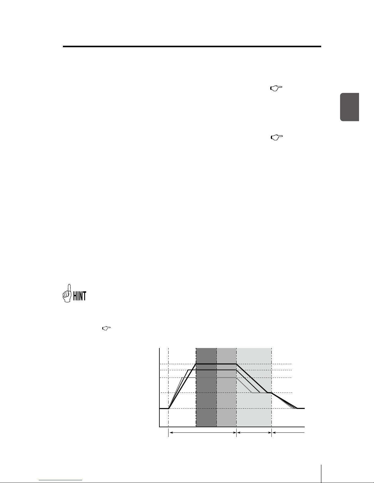
2-27
2
Basic Operation
(2) When print data is received from the computer, either of the following is
performed before printing.
g If [HEATER PREF] is set to [SOFTWARE] in the MEDIA menu ( P.3-33 [(22)
HEATER PREF]
The set temperature on the heater control menu is overwritten by the
–
temperature that is set by the RIP (print data, job), and heating starts.
When no temperature is set by the RIP (print data, job), heating starts with the
–
set temperature on the heater control menu.
g If [HEATER PREF] is set to [HEAT PANEL] in the MEDIA menu ( P.3-33 [(22)
HEATER PREF]
The temperature set by the RIP is ignored and heating starts with the
–
temperature set on the operation panel.
(3) When the current temperatures of the after heater, print heater, and preheater
reach temperatures that are 1°C lower than the set temperatures, the printer
starts printing.
g When the current temperature is higher than the set temperature, the printer
starts printing before the temperature lowers. Temperature control is performed
continuously after printing starts to maintain the heaters to their set temperatures.
(4) The heater temperature can vary during printing by changing the set
temperature in the heater control menu. Even after printing is completed,
the set temperature changed in the heater control menu remains as "set
temperature." However, the initial temperature value of each heater stored in
MEDIA REG MENU remains unchanged.
(5) The subsequent printing returns to (2).
- The three heaters work in the state displayed on the LCD regardless of the means used to
set their temperatures.
- The following gure shows the heater temperature control system for printing. The delay
time and standby time can be changed with the heater menu in the oine mode.
(
P.3-59 [Heater menu])
- The standby set temperature is xed at 35°C.
Set temperature
maintained
Standby temperature
maintained
Temperature
control end
(Time)
Print
Standby time
Delay
time
Print heater set temperature
Preheater set temperature
After heater set temperature
Standby set temperature
Ambient temperature
(Temperature)
Page 76
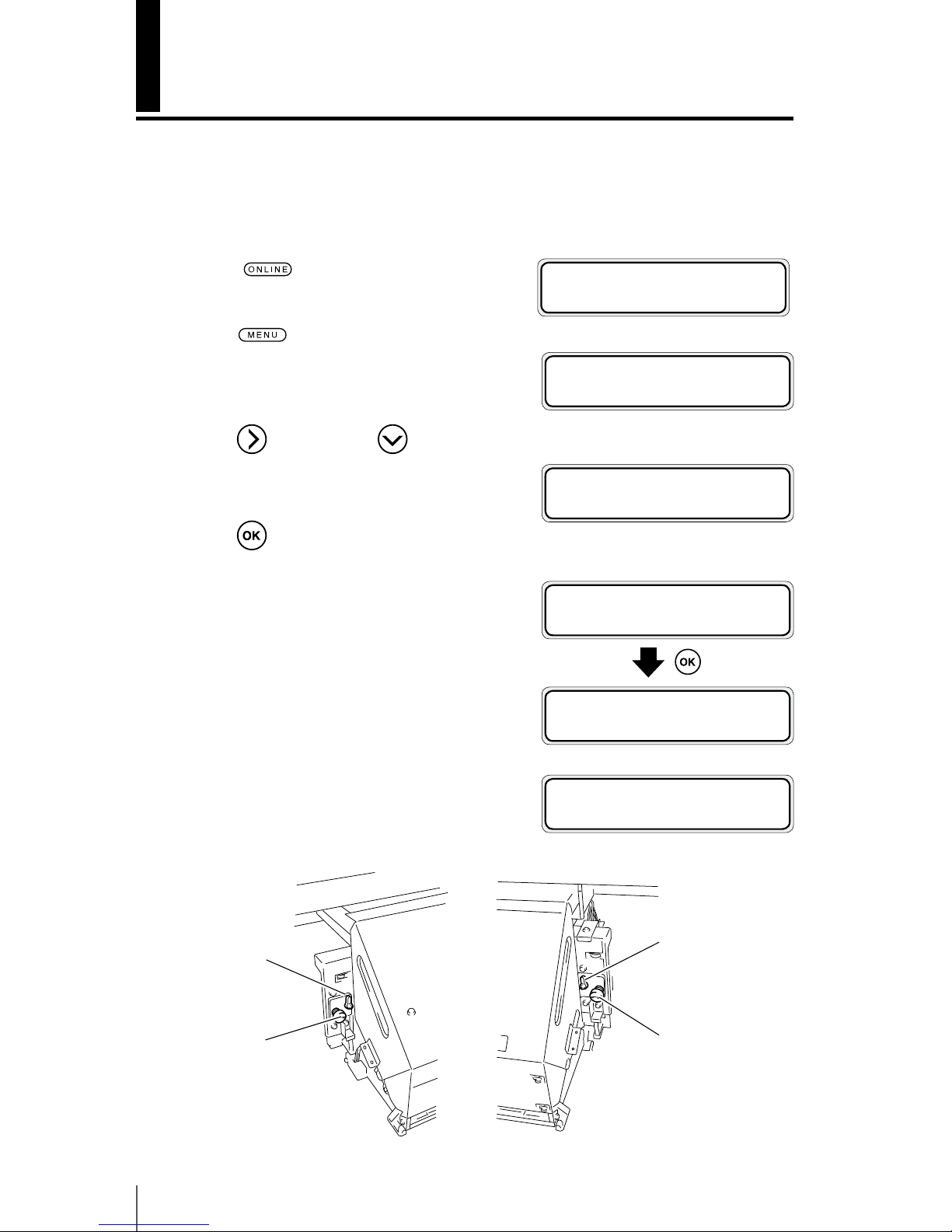
2-28
Change the Print head height
Switch the print head height to match the thickness of the media.
To switch the height of print head, use the head up down mechanism.
1
Set the printer to oine.
(Press
key.)
2
Press key to display PH.MAIN
MENU.
3
Press key and then key to display
[PH HEIGHT ADJ].
4
Press key.
5
Open the front cover and the
maintenance cover and loosen the two (2)
head securing screws.
Head securing screw
Head securing screw
Head up down
mechanism
Head up down
mechanism
#PH HEIGHT ADJ
>
h INK MEDIA REGi
f MEDIA M.ADVg
h REWIND FORM FEEDi
f PH.REC PH.MAINg
#PH HEIGHT ADJ
>OK ?
CARRIAGE MOVING
PLEASE WAIT
OPEN COVER
PH HEIGHT ADJ
Page 77
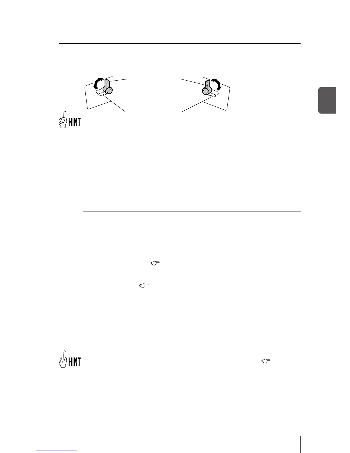
2-29
2
Basic Operation
6
Switch the height of print head with the head up down mechanism.
¯ [High] is 0.5 mm higher than [Normal].
Generally, [Normal] is used for glossy and matte vinyl chloride, and [High] is used
for tarpaulin and FF. If the media thickness exceeds 0.5 mm, [High] should be used
regardless of the media type. Use also [High] even with thin media if it is severely
wrinkled or contains irregularities that may touch the print head.
7
Tighten the two (2) xing screws.
Note
- Do not move the head up down mechanism with the head securing screws
tightened. The head up down mechanism may be broken.
- When changing the height of the print head, tighten the head securing screws
while pushing lightly the carriage downward.
- When changing the height of the print head, change [PH HEIGHT VAL] in the
MEDIA REG MENU also. (
P.3-31 [(18) PH HEIGHT VAL]
- A print shift may occur during bi-directional printing after changing the height of
the print head. In this case, adjust the bidirectional position in [BIDIR ADJ] of the
MEDIA REG MENU. (
P.3-32 [(27) BIDIR ADJ1 L] to [(32)BIDIR ADJ3 R]
- As the gap between the side plate of the printer and the carriage is narrow, if it is
hard to reach the head up down mechanism and head securing screws, move the
carriage to the right (or the left) with your hands.
- Conrm that the right and left head securing screws are tightened. If carriage
moves with the head securing screws loosened, they may strike the media or edge
guard, causing poor image quality and damage to the printer.
- Always operate the two head up down mechanisms at the same time and be sure
that they are set to the same position.
- During adjustment of the head height, the warning beep will be heard. (
P.3-56 [(5)
BEEP])
High (for thick media)
Normal (for thin (normal
thickness) media)
Page 78
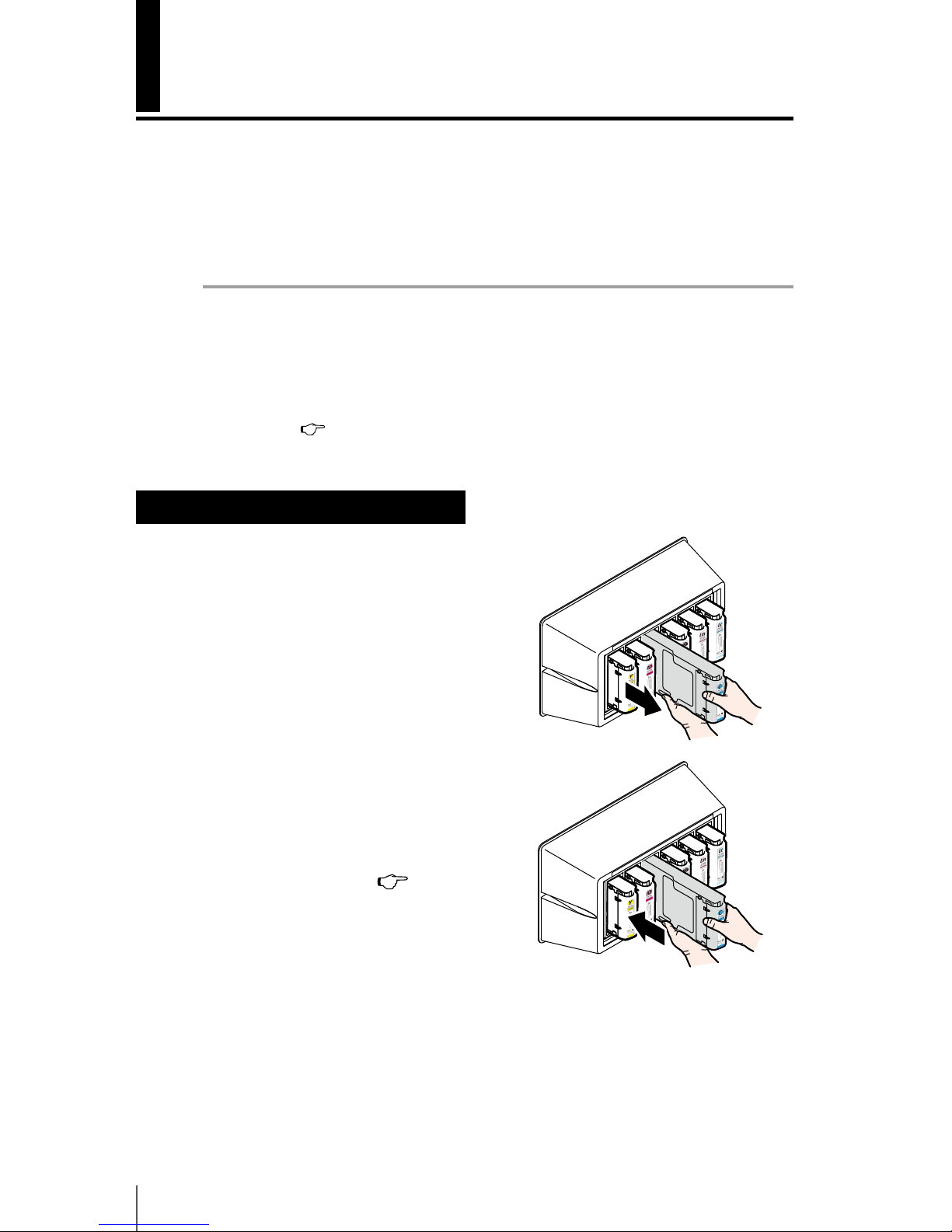
2-30
Ink cartridge replacement
This section describes the ink cartridge replacement procedure. There are three
situations requiring ink cartridge replacement:
- When the ink cartridge is empty and the ink cartridge needs to be replaced
- When no ink cartridge is installed
- When the ink cartridge is not recognized
Note
- Do not remove the ink cartridge until the ink is used up.
- Do not remove the ink cartridges during printing.
- Do not touch the green board (IC chip) of ink cartridges.
- If, after replacing an ink cartridge, print defects occur in the color of the replaced
cartridge, perform the cleaning (normal) after plugging the cartridge in and out 2
or 3 times. (
P.4-19)
Ink cartridge replacement procedure
1
Pull the ink cartridge out of the printer.
2
Insert the new ink cartridge in the correct
color slot.
Insert the ink cartridge as far as it goes.
The location of ink cartridge installation is
determined by its color. (
P.1-14 [Ink])
Do not attempt to forcibly insert an ink
cartridge in the slot of a dierent color.
3
The replacement is nished.
- When successfully nished, the printer returns to the online state or oine
state.
- If an error occurs, an error message is displayed. Go back to step
1
and start
the procedure again.
Page 79
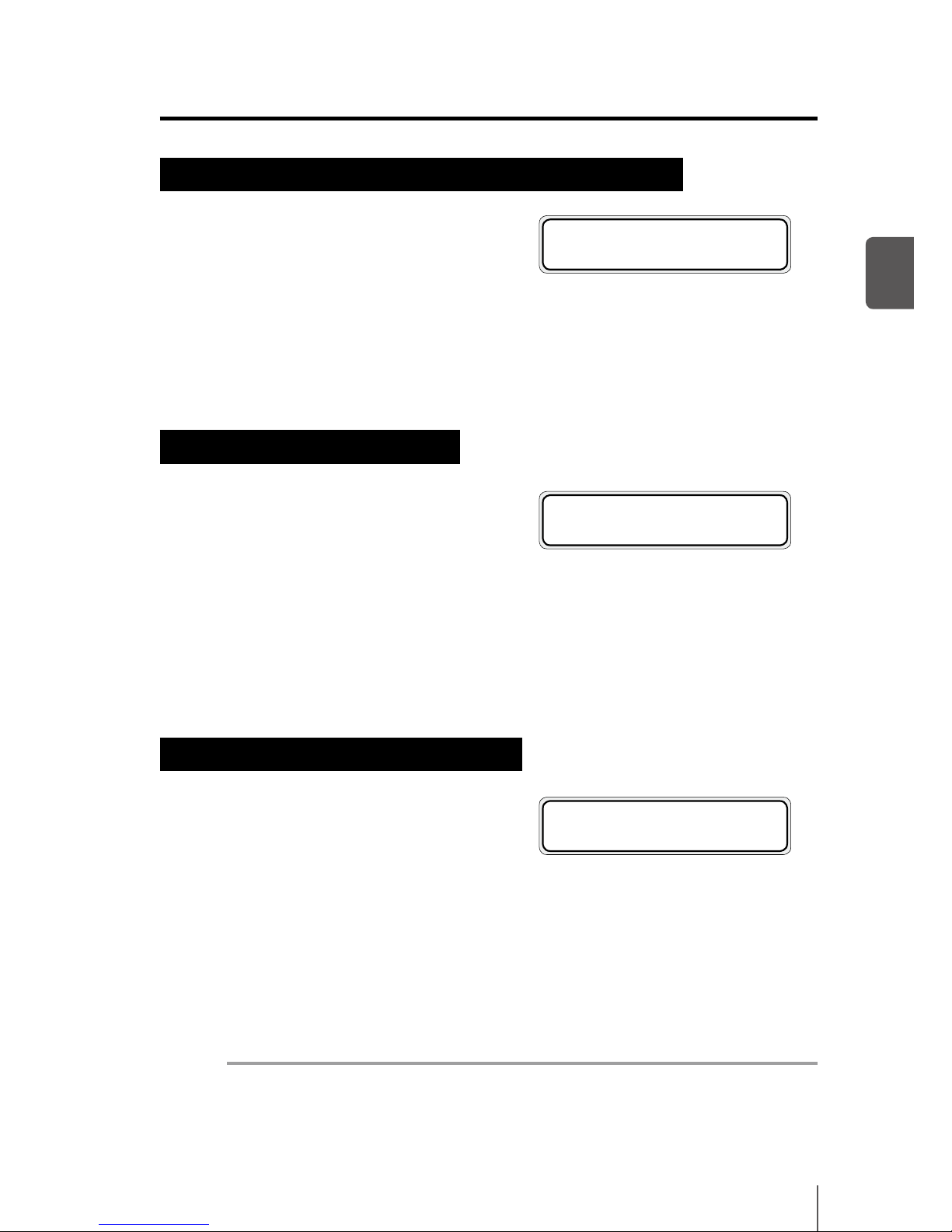
2-31
2
Basic Operation
When the ink cartridge is empty and it needs to be replaced
1
The following message is displayed.
2
Replace the ink cartridge following the ink cartridge replacement procedure.
When no ink cartridge is installed
1
The following message is displayed.
2
Install the ink cartridge following the ink cartridge replacement procedure.
When the ink cartridge is not recognized
1
The following message is displayed.
2
Re-install the ink cartridge following the ink cartridge replacement
procedure.
Note
- A ink cartridge that cannot be recognized cannot be used.
- If the message appears again after re-installing the ink cartridge, contact your
dealer or a service representative.
XX : Ink name
K : Black Lm: Light magenta
Lc : Light cyan C : Cyan
M : Magenta Y : Yellow
REPLACE
XX INK CARTRIDGE
INSTALL
XX INK CARTRIDGE
XX : Ink name
K : Black Lm: Light magenta
Lc : Light cyan C : Cyan
M : Magenta Y : Yellow
CHECK nn
XX INK CARTRIDGE
XX : Ink name
K : Black Lm: Light magenta
Lc : Light cyan C : Cyan
M : Magenta Y : Yellow
nn : Error code
Page 80
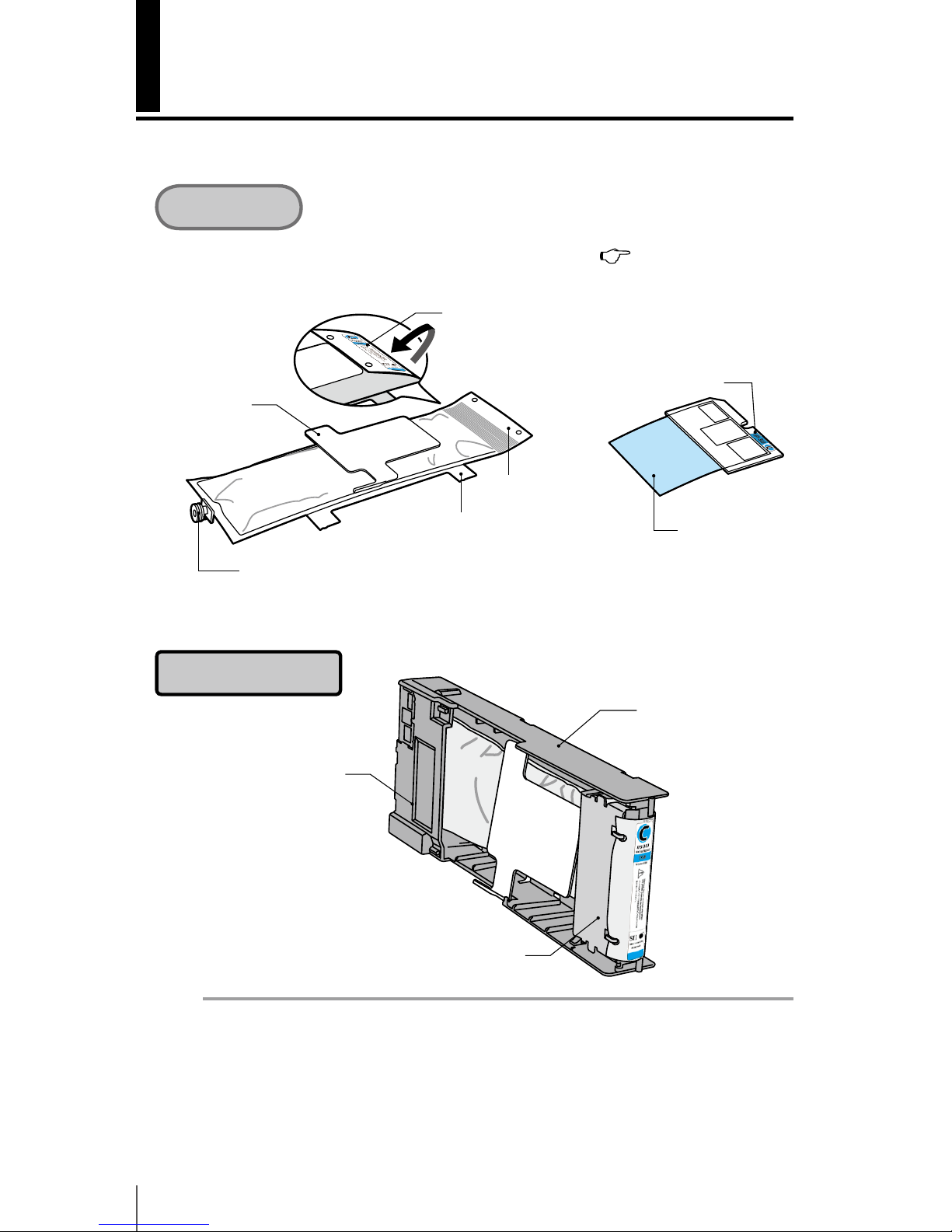
2-32
Reloadable cartridge replacement
This section describes the reloadable cartridge replacement procedure.
For details about reloadable cartridge names and types,
[Appendix 3
Options / Consumables].
Note
- Check that the colors and types indicated on the ink cartridge tail section’s color
identication label and the board’s color identication label are the same.
- Usually a small quantity of ink remains in the used ink cartridge removed from the
cartridge holder. This is normal.
- Always replace the board together with the used ink cartridge.
Consumables
Cartridge assembly
Board protective
sheet
Spout
Upper plate
Cartridge holder
Color identication label
(ink cartridge back)
Color identication label
Tail section
Lower plate
Ink cartridge for cartridge holder Board
Cartridge holder cover
Tail section xing plate
Page 81
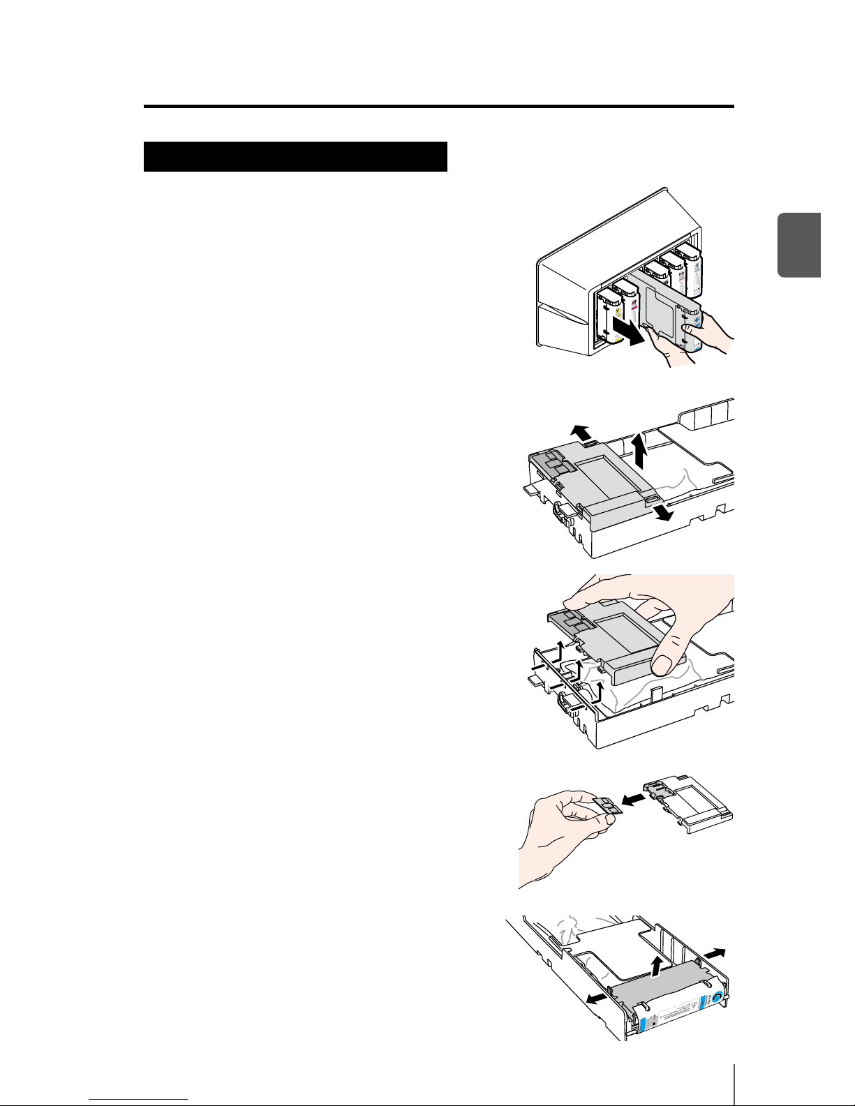
2-33
2
Basic Operation
Used ink cartridge removal procedure
1
Pull the used ink cartridge, together with the
cartridge holder, out of the printer.
2
Remove the cartridge holder cover.
While keeping the two cover securing claws
open by moving them to the outside (arrows
(1) direction), pull the cartridge holder cover
toward the top (arrow (2) direction).
Remove the cartridge holder cover in the
arrow (3) direction.
3
Remove the board from the cartridge
holder cover.
4
Remove the tail section xing plate.
While keeping the two claws securing the
plate open by moving them to the outside,
pull the tail section xing plate toward the top.
(3)
(1)
(1)
(2)
①
①
②
Page 82
2-34
5
Remove the used ink cartridge tail section
from the tail section xing plate.
6
Remove the used ink cartridge spout from the
cartridge holder.
7
Referring to the locations on the cartridge holder shown in the gure, slide
the four protrusions of the ink cartridge lower plate in the arrow direction,
and remove the ink cartridge from the cartridge holder.
Note
- Be careful not to take the silver plate o the cartridge
holder when removing the used ink cartridge.
Page 83
2-35
2
Basic Operation
Ink cartridge installation procedure
1
Make sure that the ink cartridge upper plate
is face up, and insert the tail section in the
hole shown by the shaded area in the gure
to the right.
Note
- Do not hold the ink cartridge by the upper plate only, as it may be taken o. Hold
the cartridge by both the upper and lower plates or from the bottom to insert it.
Tail section xing plate
Spout
Upper plate
Upper plate
Tail section
Lower plate
Page 84
2-36
2
Referring to the locations on the cartridge holder shown in the gure, insert
the four protrusions of the ink cartridge lower plate and slide them under the
plate guide following the arrow direction.
3
Insert the ink cartridge spout in the cartridge holder.
Note
- Do not install the ink cartridge with the spout tilted.
Page 85
2-37
2
Basic Operation
4
Insert the board in the cartridge holder
cover.
With the golden surface of the board facing up,
insert it so that the board shape matches the
shape of the cartridge holder cover.
Note
- Do not take the board protective sheet o until you install the reloadable
cartridge to the printer. This sheet prevents contact failure.
5
Pull softly the tail section of the ink
cartridge.
6
Install the cartridge holder cover.
Insert the three protrusions of the cartridge
holder cover in the cartridge holder holes.
Hook the cartridge holder cover to the claws to
secure it.
Note
- Make sure that the board protective sheet does not get between the cartridge
holder and the cartridge holder cover.
Page 86
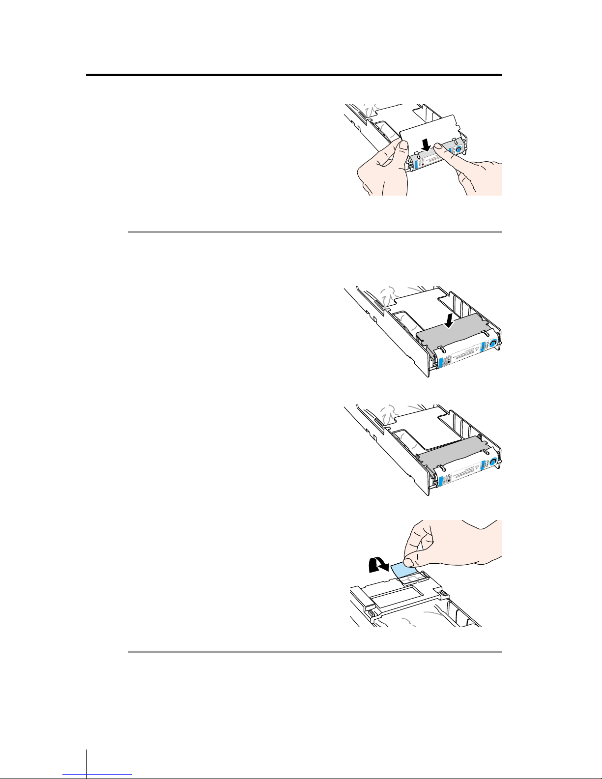
2-38
7
Insert the tail section xing plate hooks
into the ink cartridge tail section holes to
attach it.
Note
- Do not apply an excessive force as the ink cartridge holes may be deformed.
8
Hook the tail section xing plate to the
cartridge holder claws.
9
Remove the board protective sheet.
Note
- Be sure to remove the board protective sheet. Installing the ink cartridge to the
printer without removing the board protective sheet may cause a malfunction.
Page 87
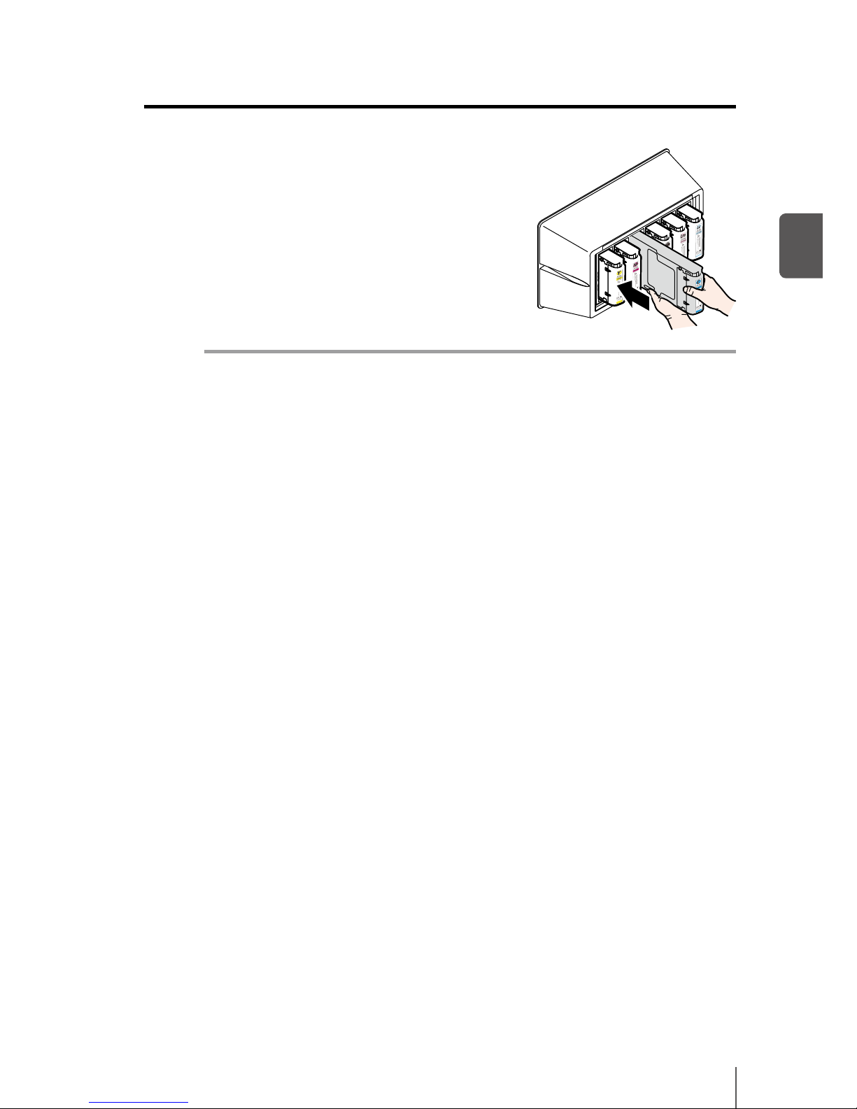
2-39
2
Basic Operation
10
Insert the reloadable ink cartridge into the
slot.
Note
- Check that the color on the ink cartridge tail section label and the color on the ink
box label are the same.
- Do not push strongly the tail section xing plate toward the inside.
Page 88
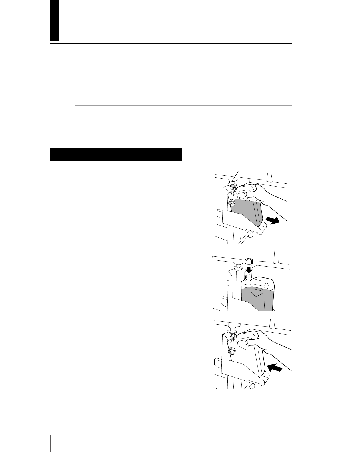
2-40
Waste ink bottle replacement
This section explains the waste ink bottle replacement procedure. There are two
situations that require the waste ink bottle replacement procedure:
- When no waste ink bottle is installed
- When the waste ink bottle is full
The procedure for each case is described below.
Note
- Do not replace the waste ink bottle during printer operation.
- When replacing the bottle, use caution not to spill the ink. Use protective paper to
prevent soiling.
Waste ink bottle replacement procedure
1
Remove the bottle from the waste ink spout
(tube) by slightly tilting the full waste ink
bottle.
2
Put the cap on the bottle and remove the
bottle.
3
Wipe o any ink stains around the waste ink
bottle.
4
Install a new (empty) waste ink bottle.
Waste ink spout
Page 89
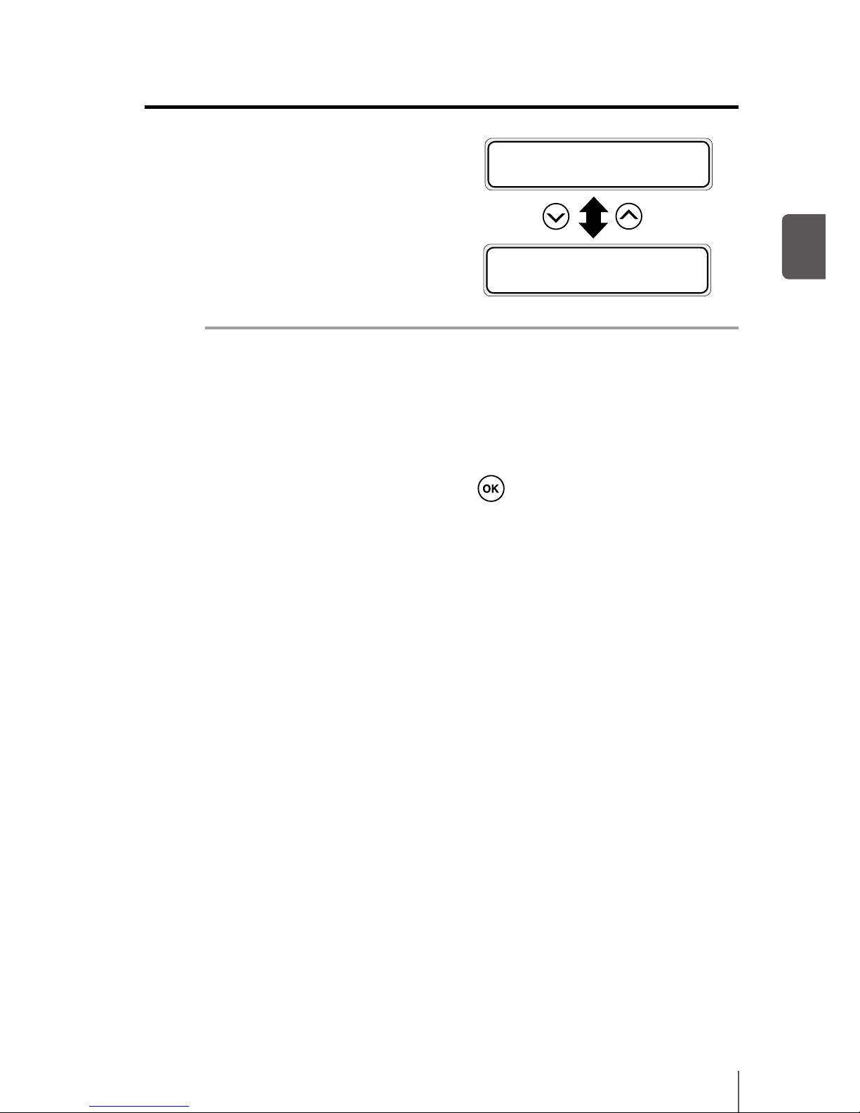
2-41
2
Basic Operation
5
The following message is displayed to
reset (clear) the waste ink counter.
Note
- The printer automatically calculates waste ink with a counter and displays the
message prompting replacement of the waste ink bottle when the waste ink
bottle is full. As there is no sensor for the waste ink level, this calculation is just an
estimate. Therefore, if the waste ink counter is reset (set to *YES) and the bottle is
not empty, the waste ink may overow.)
6
Select “BOTTLE EMPTY? * YES” and press key.
#BOTTLE EMPTY?
*YES
#BOTTLE EMPTY?
*NO
Page 90
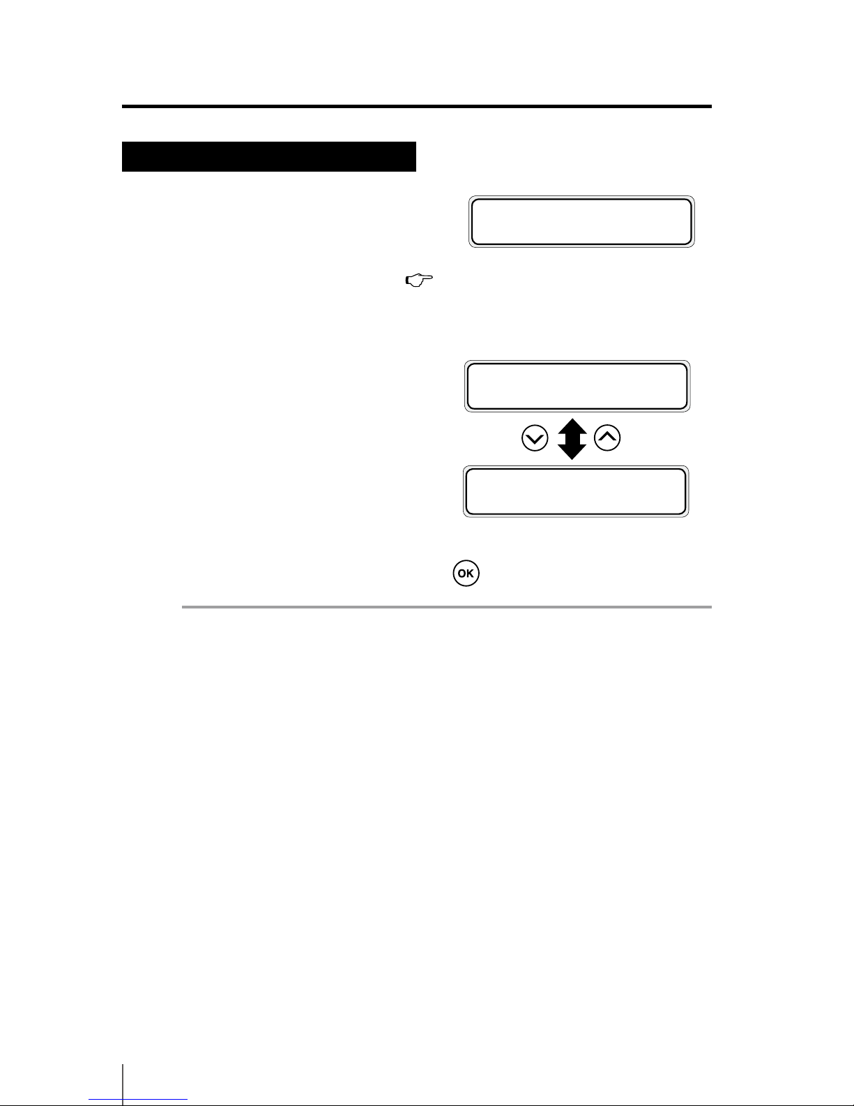
2-42
When no waste ink bottle is installed
1
The following message is displayed.
2
Install a waste ink bottle. Refer to P.2-40 [Waste ink bottle
replacement] steps 1 to 4.
3
The following message is displayed to
reset (clear) the waste ink counter.
4
Select “BOTTLE EMPTY? * YES” and press key.
Note
- Select YES when installing a new (empty) waste ink bottle.
- If the waste ink bottle is removed only to visually check the level in the waste ink
bottle, select *NO.
#BOTTLE EMPTY?
*YES
#BOTTLE EMPTY?
*NO
BOTTLE OUT
INSTALL BOTTLE
Page 91
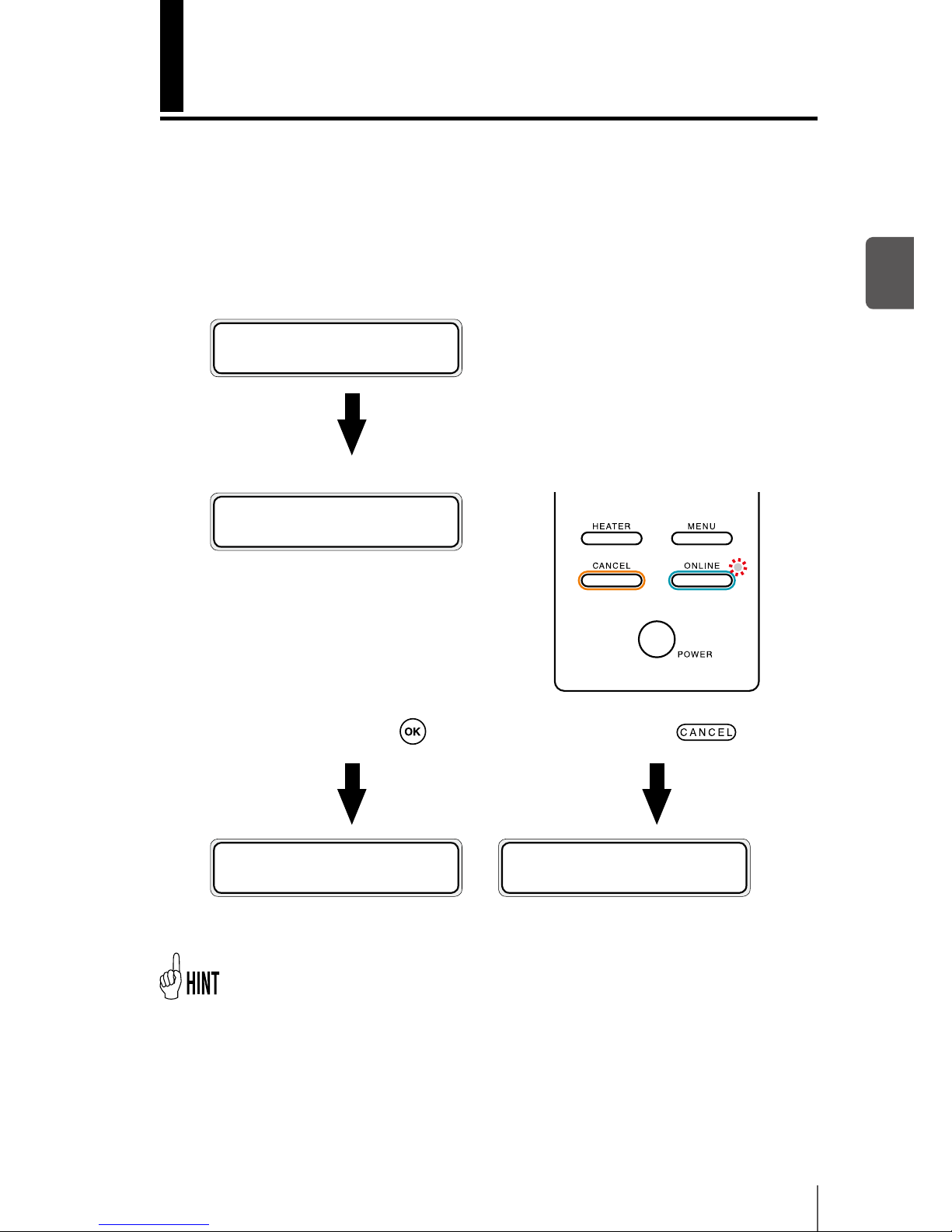
2-43
2
Basic Operation
The media was skewed.
The printer checks for media skew when the printing starts and at every three
meters of print (*). If the printer detects the skew level is larger than specied, the
print operation is suspended and an operation panel message appears so that
you can select to continue or cancel the print.
(* When [SKEW CHECK] in [MEDIA REG MENU] is set to ON.)
During printing
PRINTING
NORMAL L ND BI
The Printer checks for media skew. Media skew was detected.
MEDIA MISALIGNED
OK/CANCEL
Continue printing with the key.
Stop printing with the
key.
PRINTING
NORMAL L ND BI
NO MEDIA LOADED
LOAD MEDIA
[CANCEL] is recommended.
- If you select [OK] to continue the print, the rest of the suspended printing job is started.
However, the media may be disengaged from the media edge guards, or the media may
be jammed. When the printout is lengthy, the skew may be worse, which may damage
the Printer.
Page 92

2-44
Page 93

Menu of Operation panel
This section explains the basic operations and structure of the
operation panel menu, and the operations in each menu.
Basic menu operation in oine mode ....................... 3-2
Explanation of each menu operation .......................3-17
(Content of this section)
3
Page 94
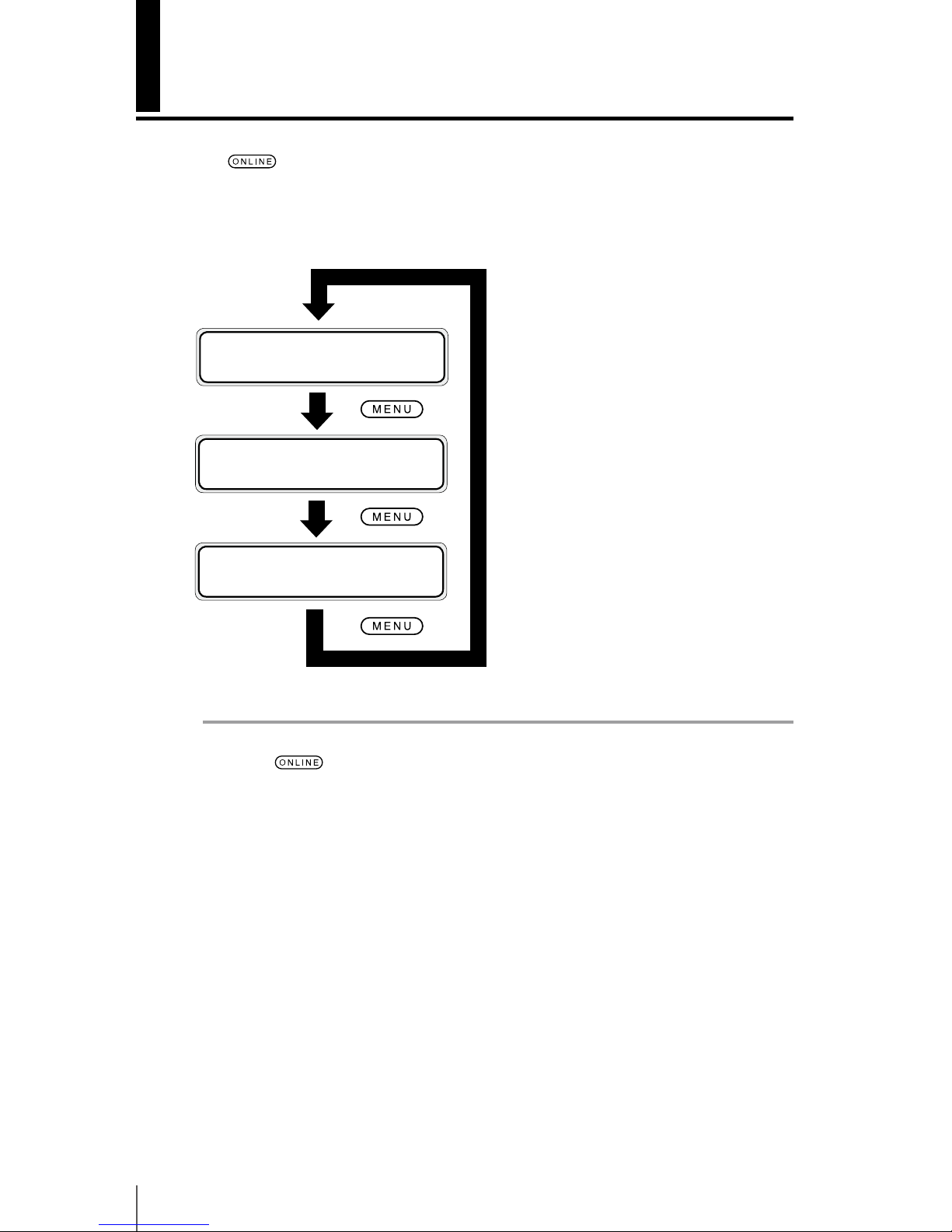
3-2
Basic menu operation in oine mode
Press key while the printer is in idle mode (online status) to put the printer
in oine mode, display the menu on the LCD and enable menu operations.
hINK MEDIA REGi
fMEDIA M.ADVg
hPRINTER SETUPi
fADJUST HEATERg
hREWIND FORM FEEDi
fPH.REC PH.MAINg
Note
- If key is pressed, the printer goes into oine state, even if an error
message is displayed. However, depending on the error type and the solution being processed, the oine state may not be available. In this case,
solve the error before going to the oine state.
Page 95

3-3
Menu operations
3
Menu layer structure
The menu consists of the following layers.
<First layer menu>
This is the menu group displayed rst. Several menus may exist on the lower layer.
<Second layer menu>
This menu group is under the rst layer.
<Third layer menu>
This menu group is under the second layer.
<Parameter>
This selection is used to select or enter items of the selected menu. Inputs include
numerical values, characters, selection and execution.
Page 96
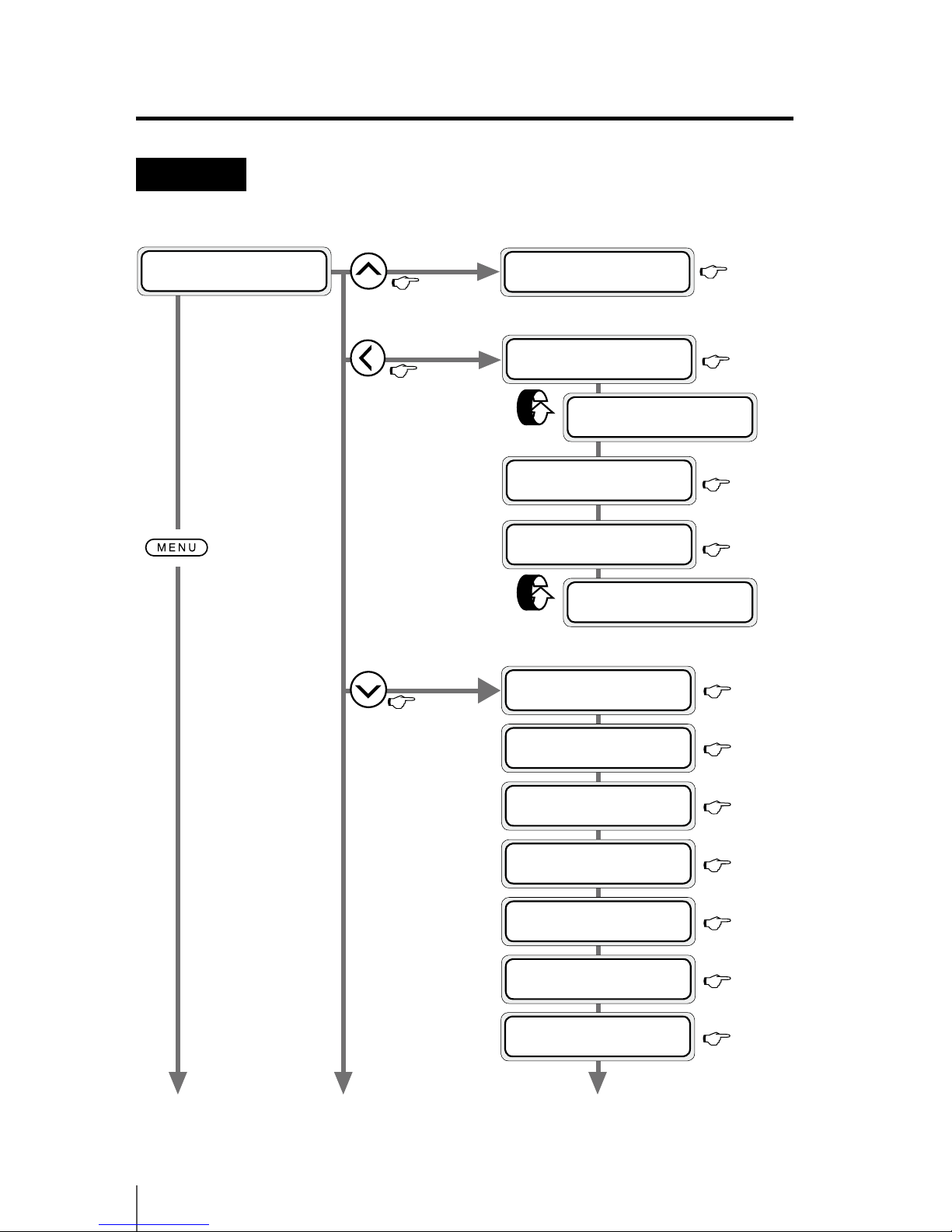
3-4
Menu tree
P.3-17
(1)
(2) (3)
INK MENU
P.3-17
MEDIA MENU
P.3-18
MEDIA REG
MENU
P.3-20
XX INK LEVELZZZ%
DATE:YY/MM/DD
ROLL(PAPER)
YYYYmm
SHEET(PAPER)
YYYYmm×ZZZZmm
NEST(PAPER)
YYYYmm
h
INK MEDIA REG
i
f
MEDIA M.ADV
g
P.3-18
P.3-18
#PRINT DIRECTION
>01:BIDIR
#DENSITY
>01:NORMAL
#SMART PASS
>01:LOW
#PRINT MODE
>01:NORMAL
#RENAME MEDIA
>01:PAPER
#FLATTEN TIME
>01:NONE
#SELECT MEDIA
>01:PAPER
P.3-19
P.3-24
P.3-24
P.3-24
P.3-25
P.3-26
P.3-27
P.3-28
REMAINING MEDIA
ZZZm
REMAINING MEDIA
ZZZm
Toggle display
Toggle display
Page 97
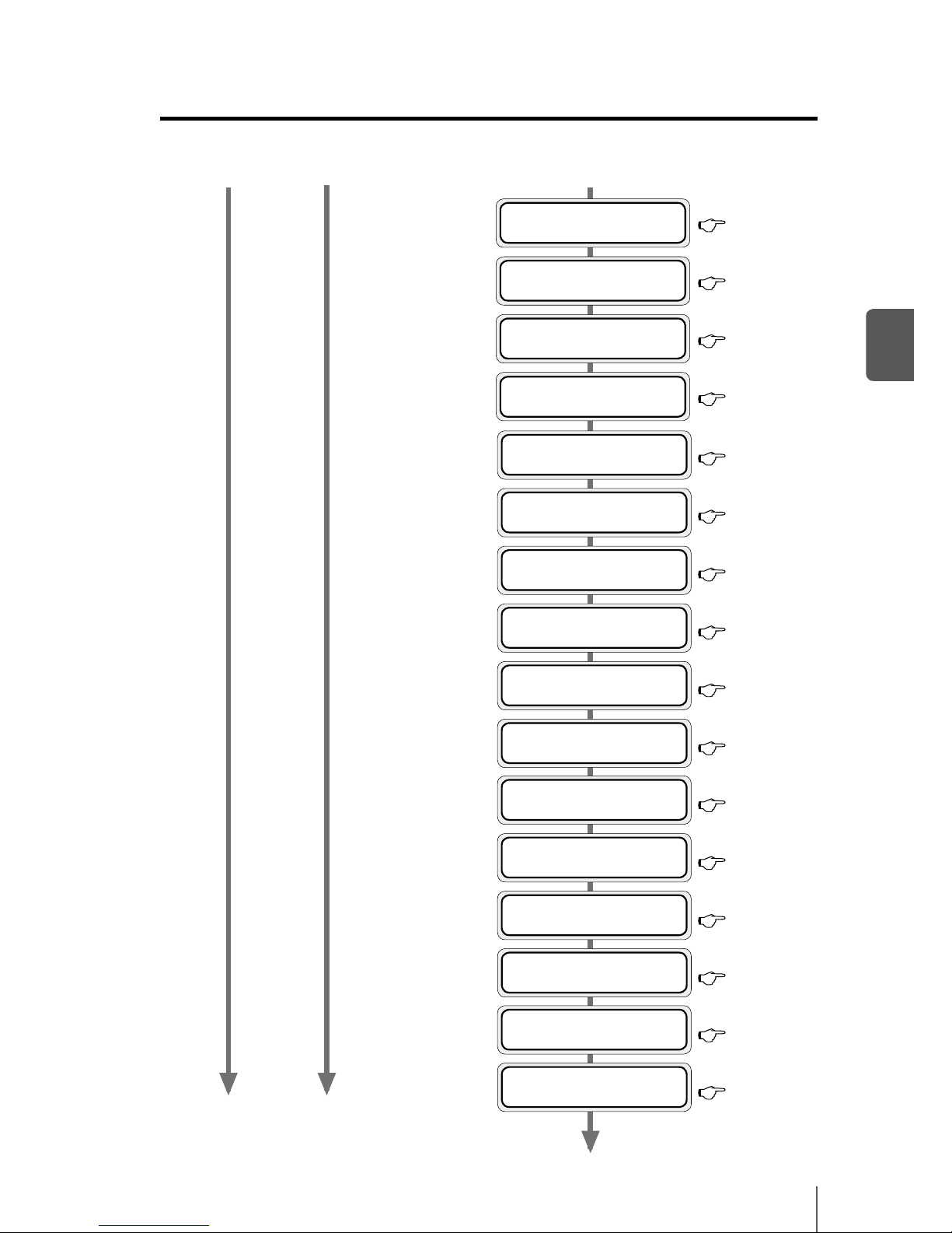
3-5
Menu operations
3
(4)
(3)
P.3-30
P.3-30
P.3-31
P.3-31
P.3-31
P.3-32
P.3-33
P.3-33
#LEADING EDGE
>01:NORMAL
#SUCTION FAN LEVEL
>01:NORMAL
#AFTER HEATER T
>01:
**
˚C
#PRINT HEATER T
>01:
**
˚C
#PRE HEATER T
>01:
**
˚C
#PRINT MODE PREF
>01:SOFTWARE
#COLOR STRIPE
>01:ON
#PH CLEANING
>01:ON
#ADVANCE PREF
>01:SOFTWARE
(1)
(2)
P.3-33
q Basic menu operation in offline mode
#TUR MODE
>01:LOOSE
#USE EDGE GUARD
>01:YES
#MEDIA ADV MODE
>01:FWD ONLY
P.3-29
P.3-29
P.3-29
P.3-32
#PH HEIGHT VAL
>01:NORMAL
P.3-33
#PH REST PERIOD
>01:0000CYCLES
#HEATER PREF
>01:SOFTWARE
P.3-34
#SKEW CHECK
>01:ON
P.3-29
Page 98
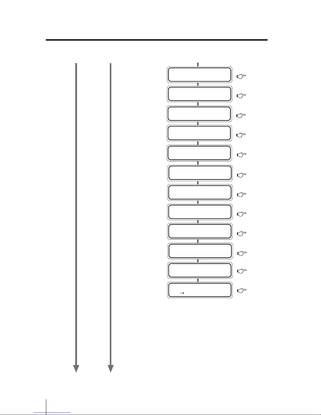
3-6
(4)
(1)
(2)
P.3-37
P.3-38
P.3-37
#DELETE MEDIA
>02:TYPE02 OK ?
#PASTE MEDIA
>01 02
*
#COPY MEDIA
>01
#BIDIR ADJ2 L YY
>01:+00
#BIDIR ADJ2 R YY
>01:+00
#BIDIR ADJ3 L YY
>01:+00
#BIDIR ADJ3 R YY
>01:+00
P.3-36
P.3-36
P.3-36
P.3-37
#BIDIR ADJ1 R YY
>01:+00
P.3-35
P.3-35
P.3-35
#MEDIA ADV VALUE
>01:100.00%
#BIDIR ADJ1 L YY
>01:+00
P.3-34
#REMAINING MEDIA
>01:YYYm
#PH REST TIME
>01:10sec
P.3-34
Page 99
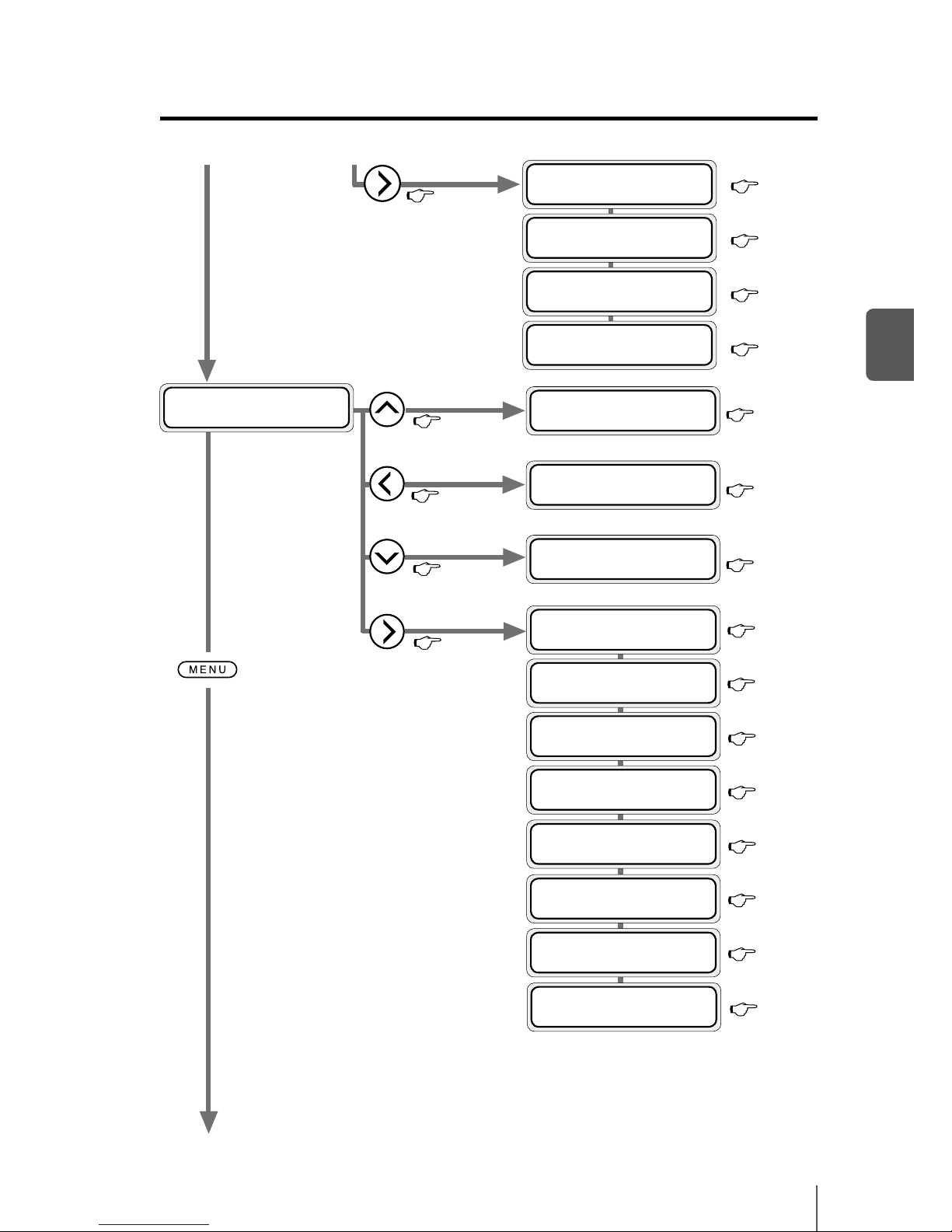
3-7
Menu operations
3
REWIND MENU
P.3-46
(5)
h
REWIND FORM FEED
i
f
PH.REC PH.MAIN
g
PH.REC MENU
P.3-47
FORM FEED
MENU
P.3-48
PH.MAIN
MENU
P.3-49
#REPLACE WIPE LIQUID
>
#PH RECOVERY
>NORMAL
#REPLACE WIPER BLADE
>
#PH HEIGHT ADJ
>
#WASH PRINTHEADS
>
#INK SYSTEM OPT
>STORE INK SYS
#CAP CLEANING
>
FEEDING MEDIA
REWINDING MEDIA
#RESEAT PRINTHEAD
>
#REPLACE WIPE SPONGE
>
P.3-46
P.3-49
P.3-48
P.3-47
P.3-50
P.3-50
P.3-51
P.3-50
P.3-49
(1)
P.3-50
q Basic menu operation in offline mode
P.3-51
P.3-41
P.3-44
P.3-42
P.3-44
M.ADV MENU
P.3-40
#SING. ADV
#EXECUTE>
#AUTO BIDIR ADJUST
#EXECUTE>
#MULTI ADV
#EXECUTE>
#MANUAL BIDIR ADJUST
#EXECUTE>
(2)
Page 100
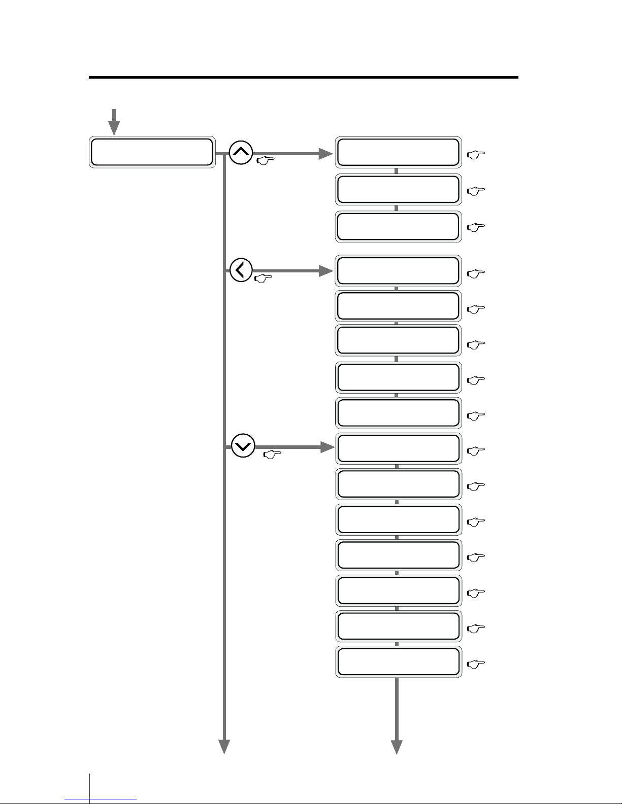
3-8
SETUP
MENU
P.3-57
PRINTER MENU
P.3-52
h
PRINTER SETUP
i
f
ADJUST HEATER
g
(6)
ADJUST MENU
P.3-53
(5)
P.3-52
P.3-52
P.3-52
P.3-53
P.3-54
P.3-54
P.3-55
P.3-57
(7)
#LANGUAGE
>ENGLISH
#CONFIG PRINT
>
#HISTORY PRINT
>
#ERROR LOG PRINT
>
#NOZZLE POS ADJ
#EXECUTE>
#PRINT HEAD ADJUST
#EXECUTE>
#NOZZLE PRINT
#EXECUTE>
#EDGE SENSOR ADJUST
#EXECUTE>
P.3-56
#TUR ADJ PRINT
#EXECUTE>
P.3-57
#TIME ZONE (GMT+)
*
YY/MM/DD HH:MM +xx
P.3-58
#LENGTH UNITS
>MILLIMETER
P.3-58
#TEMPERATURE UNITS
>CENTIGRADE
P.3-58
#BEEP
>ON
P.3-59
#BOOT VERSION
*
X.XX
P.3-59
#PRINTER FW VER
*
X.XX_YY
 Loading...