

Page 1
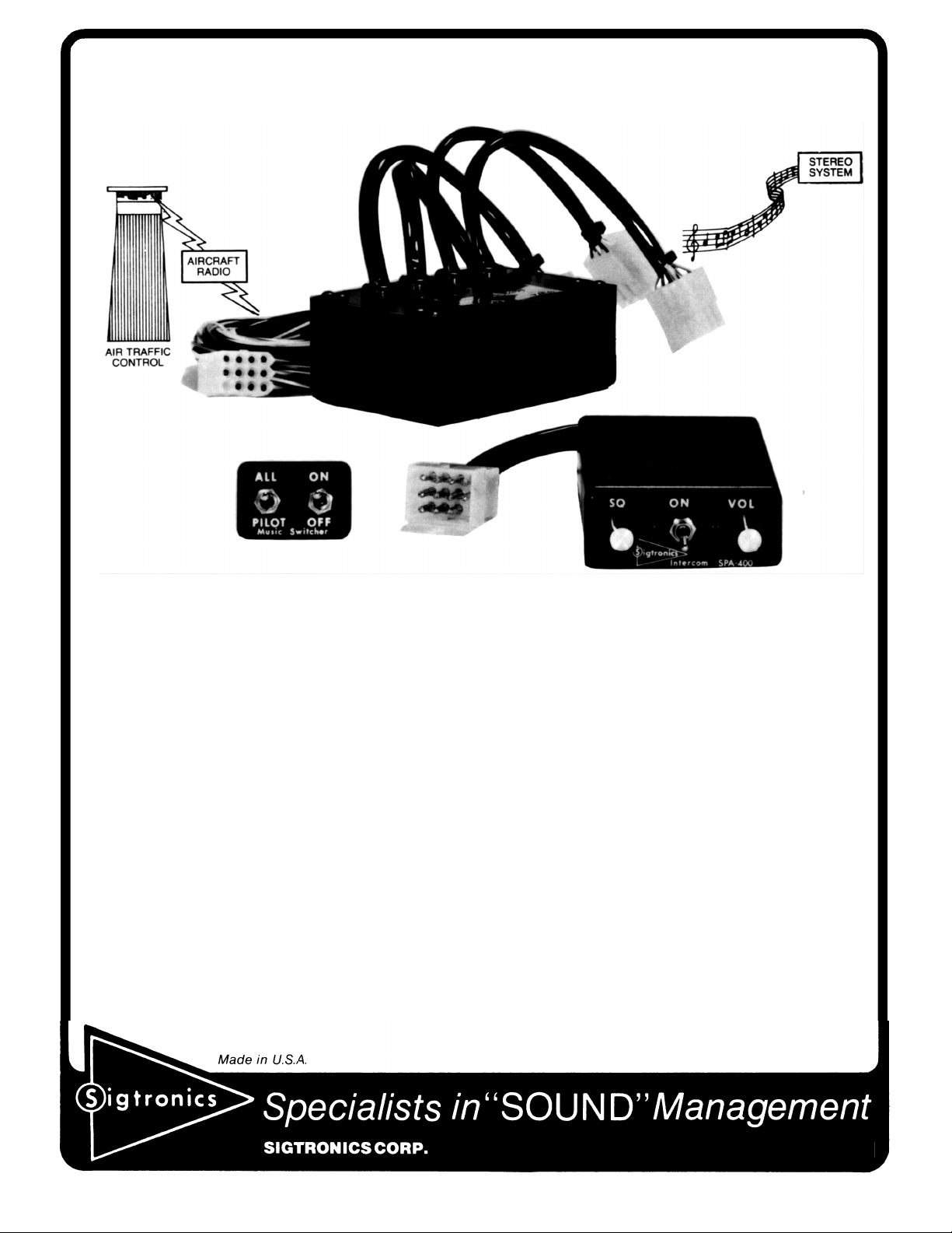
Sigtronics’ STEREOCOM-400
Discover the pleasure of flying with stereo music while
maintaining VHF and passenger communications!
The STEREOCOM is a voice actuated intercom that allows pilot copilot and two passengers to intercom, listen to their stereo, yet hear
the VHF radio. The pilot and co-pilot can also transmit using push-totalk switches through the VHF radio to ATC. The music is
automatically interrupted when the VHF radio is active (transmit or
receive) or when talking on the intercom. The passengers may listen
to music only; music interrupted by VHF and intercom; or VHF and
intercom only. (See Mode Selection Table for various operating
modes.)
CONFIGURATION: The Stereocom is configured in two sections:
An SPA-400 intercom with transmit capability, and an RES-400
Stereo Switcher. Both units may be installed at the same time, or the
switcher section may be easily added to an existing SPA-400
Transcom installation. The SPA-400 unit is in a 1 x 2.5’ x 4 deep
panel mount chassis, which can be mounted either in a horizontal or
vertical position. Weight: 4.5 oz. The RES-400 unit is in a 4 x 2.9’ x 2
chassis that is to be mounted remotely. Weight: 7.5 oz. All stereo
headphone jacks, mike jacks, switches, controls, harness and
connectors are supplied. Power: Stereocom operates 10 through 34
VDC without switching or adapters.
Intercom Panel Controls:
Power Switch — Turns intercom on and off.
Volume Control — Controls intercom volume, only.
Squelch Control — Controls the threshold of intercom amplifier
turn-on. It is used to adjust for variations in background noise
found in various aircraft.
Switcher Panel Controls:
Music Switch — Turns switcher on or off.
Mode Selection Switch — Four modes of operation are
possible with Stereocom using the Music On/Off and Pilot/All
switch. These are described in detail in the Mode Selection
Table. In general, the modes allow the passengers to listen to
uninterrupted music or hear the VHF and intercom. The pilot’s
and co-pilot’s music is always interrupted by the VHF and
intercom to assure fail safe operation. In order to eliminate VHF
interrupt, it is necessary to turn the VHF radio volume down or
off.
HEADSETS: The Stereocom is normally supplied to accommodate
high impedance (300 to 600 ohm) stereo headsets, such as the
Sigtronics Stereo headsets.
ENTERTAINMENT SYSTEM SELECTION: See “Helpful Hints” on
back page.
178 East Arrow Highway, San Dimas, CA 91773 909-305-9399
Page 2
INSTALLATION FOR COMPLETE SPA-400 pIus RES-400 SYSTEM
(If RES-400 is to be added to existing SPA-400 installation, proceed to Installation Retrofit.)
SPA-400 CHASSIS INSTALLATION
Hardware Supplied: (SPA-400, RES-400)
Four Headphone Output Jacks — Accept .250” stereo headphone
plugs.
Four Microphone Input Jacks — Accept standard .206” aircraft
microphone plugs.
Mike Jack Insulating Washers: 4 shoulders and 4 flat.
Transcom Panel: Lettered on both sides.
Control Knobs (2), Switch Nuts (3), 4-40 Screws (2)
Switcher Panel and harness
Template (Hole size pattern)
Aircraft/Intercom interface cable (4 ft. long)
Connectors for fabricating extension cable
The location selected requires a minimum front panel area of 21/2” by
1”. Depth required behind panel is 4” plus cable access.
Allow approximately 1” by 11/2” space nearby to mount the RES-400
switcher panel.
CAUTION: Move aircraft flight controls through limits of travel while
observing selected area to make certain intercom components will
not interfere with aircraft control components.
PANEL PREPARATION:
1. Position adhesive template on aircraft panel in selected area.
2. Center punch each hole at cross lines. (The five holes are in a
straight line and equally spaced 0.4” apart.)
3. Drill 1/8” pilot hole all five places.
4. Enlarge holes to 1/4” and 3/8” per template.
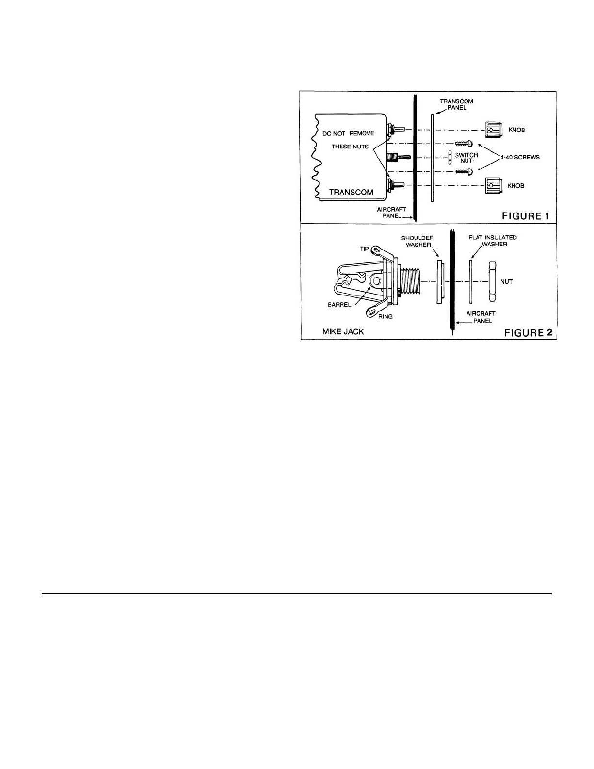
MOUNTING CHASSIS: See Figure 1
1. Remove nut from Transcom ON-OFF switch bushing.
2. Remove knobs from VOL and SQ controls using .050 Allen wrench.
DO NOT REMOVE nuts from VOL and SQ control potentiometers.
3. Remove two 4-40 screws and remove panel from TRANSCOM
chassis.
4. Insert Transcom from rear of aircraft panel with appropriate arrow
pointing upwards.
5. Install panel and lightly thread nut on to ON-OFF switch. Nuts and
washers on VOL and SQ controls should fit inside the 3/8” diameter
holes drilled in aircraft panel.
6. Install two 4-40 screws through holes in Transcom panel. Tighten
ON-OFF switch nut.
7. Install knobs on VOL and SQ control shafts.
MOUNTING HEADPHONE AND MICROPHONE JACKS
1. Locate mounting areas. (One mike and one headphone jack for
each headset.)
2. Drill 3/8” diameter holes for headphone jacks and install.
3. Drill 1/2” diameter holes for mike jacks and install with insulating
washers supplied. (See Figure 2)
4. Terminals on the stereo phone jacks may be identified per the mike
jack shown in Figure 2. The phone jack bushings (sleeve terminal)
must be grounded to airframe or wired to aircraft ground.
INSTALLATION RETROFIT
If the Transcom SPA-400 has been previously installed, the RES-400
Switcher may be added as follows:
1. Mount the RES-400 chassis per paragraph “RES-400 Switcher
Chassis Installation”
2. Install the Music and Mode Switches and route the harness per
paragraph “Switcher Harness Installation”.
3. Unplug SPA-400 from its wiring harness and insert Connectors J1
and P2 on the RES-400 as shown in Figure 3. Connect remaining
plugs per Figure 3.
4. Remove the headphone jacks from the pilot, co-pilot, and passenger
1. As in mounting the intercom, select a mounting location which will
RES-400 SWITCHER CHASSIS INSTALLATION
not cause interference with flight controls. (If space allows, mounting
of the Switcher within a few inches of the intercom will allow
connectors J1 and P1 to be mated directly. Otherwise, an extension
cable may be fabricated, from the connectors provided, to permit
mounting the switcher chassis elsewhere.
2. Remove the four corner panel screws and remove unit from case.
3. Drill aircraft with same hole pattern as in the switcher case. Use a
#27 drill. (Clearance drill for 6/32”)
4. Secure case to aircraft with screw heads inside switcher case for
circuit board clearance. (Care should be taken not to crush
grommets while applying torque to screws.)
5. Replace unit in the case and secure.
SWITCHER HARNESS INSTALLATION
1. Select area on panel and drill ¼” diameter holes for Music (On/Off)
and Mode (Pilot/All) Switches.
2. Mount switches with bushing key slots down.
3. Route harness to Switcher to clear aircraft controls and secure with
suitable ties.
positions in aircraft. Wires which had been connected to the phone
jacks should be cut, insulated and tied back. If two or more wires
appear on a single jack terminal, they should be cut free of the jack,
then spliced together before insulating and tying back. Do Not Dis-
turb Microphone Jacks.
5. Replace headphone jacks with three-terminal type “stereo” jacks
supplied with the RES-400 switcher. Connect wires to the stereo
jacks per Figure 3. Terminals on the stereo phone jacks may be
identified per the mike jack shown in Figure 2. The jack bushings
(barrel terminal) must be grounded to the airframe or wired to
aircraft ground.
Page 3

WIRING INSTRUCTIONS
Connections should be made as shown in Figure 3 and as indicated
in Table 1.
*1. White/red (pilot push-to-talk) must correspond with white/black
(pilot mike input) as shown.
*2. The blue wire from Pin 3 must be connected to the aircraft radio
headphone output — NOT the speaker output.
*3. Connect all mike jack grounds to Point A as shown in Figure 3.
PIN
#J2
1 White/Black Pilot Mike Input
2 White/Red *1
WIRE
COLOR
FUNCTION CONNECT TO
Ring Terminal of Pilot
Intercom Mike Input Jack
Pilot Transmit
Switch Input
Pilot Transmit Switch (PTT)
3 Blue *2 Intercom Output Radio Headphone Output
4 Black *3 Ground
Transmit Relay
5 White *4
(Key) Control
Output
Hand Mike Jack Ground
Terminal (Point A)
Tip Terminal of Aircraft Mike
Jack or Key Input of Aircraft
Radio or Audio Panel
Ring Terminal of Aircraft
6 Brown Mike Audio Output
Mike Jack or Input of Air
craft Radio or Audio Panel
(Use black washers supplied to insulate the mike jacks from aircraft
chassis ground.)
*4. Do NOT connect transmit switches to white (key) wire.
*5 Red wire may be connected to either 12 (1 4V) or 24 (28V)
power source.
*6. Tan wires from Pins 8 and 9 are only used on 4-way
installations.
PIN
WIRE
#J2
COLOR
7 Red *5
8 Tan *6
9 Tan *6
10 White/Blue
White/
11
Orange
FUNCTION CONNECT TO
12V or 24 VDC
Power Input
Rear Mike Input
(either Side)
Rear Mike Input
(Either Side)
Co-Pilot Transmit
Switch
Co-Pilot Mike Input
Intercom Circuit Breaker
Ring Terminal of Rear
Intercom Mike Jack
Ring Terminal of Other
Rear Mike Jack
Co-Pilot Transmit Switch
(PTT)
Ring Terminal of Co-Pilot
Intercom Mike Input Jack
12 No Connection
TABLE 1 — *See Wiring Instructions Below
Page 4

FINAL CHECKOUT AND ADJUSTMENT
After the unit is installed, again check that the SPA-400 intercom chassis,
RES-400 switcher chassis, jacks and wiring harness are clear of all air-
SPA-400 INTERCOM OPERATING INSTRUCTIONS
I. INTERCOM MODE
A. Put on headset/s and position the boom mike close to the mouth,
as is the practice with a hand-held mike. Voice clarity is best when
mike is at one side of the mouth and ¼” from the lips.
B. Set audio panel to “Headphone” position, if applicable.
C. Turn power on” and set volume control to a low level (1/4th to
1/3rd open for best signal to noise ratio).
D. Set Music switch to “OFF” and Mode Switch to “ALL”.
E. Adjust Squelch Control clockwise to the point where ambient
background noise becomes audible. Then rotate counter clockwise a
very small amount and wait (approximately 1 second) for background
noise to diminish. Very small adjustments may be necessary it
aircraft background noise changes significantly (such as from taxi to
take-off power conditions). The above procedure is necessitated by
the fact that the squelch system is a fast attack/slow off system.
II. RADIO TRANSMIT MODE — Transmitting from both pilot and copilot
positions is possible on a one-at-a-time basis. The transmitting mike
disables all other mikes. When you are ready to talk to ATC, depress
the transmit switch on your yoke and your voice is automatically
transmitted via the aircraft radio. (You will hear your own voice when
transmitting via the aircraft radio side-tone.) If the radio does not
have side-tone, then you will not hear your voice.
(A minor modification to the Transcom will enable it to simulate sidetone.)
craft operating controls and cause no interference with them. Check out
the system function by following the Operating Instructions.
It may be necessary at this time to adjust the Transcom mike output
to the aircraft radios. A small, square, adjustable trimmer potentiometer is provided inside the unit for this purpose. It is accessible
through a hole in the side of the case, marked “Mod. Adj.,” and can
be adjusted with a screwdriver. In the event of overmodulation
(garbled), or reports of weak transmissions over the aircraft radio,
an appropriate adjustment can be made. Clockwise rotation
increases the output level to the aircraft radio mike input. Counterclockwise rotation decreases modulation level. This adjustment
sometimes needs to be made after initial installation of the intercom,
or if a new radio is installed. (The output is set for unity gain at
Sigtronics.)
III. RADIO MONITORING — The aircraft radio is always heard with the
Transcom switched on or off to provide fail safe operation.
IV. SOLO FLIGHTS — Since the intercom is not needed during solo
flights, it may be turned off. The pilot will still hear the aircraft radio,
and may transmit to ATC via his push-to-talk switch. (Co-pilot
position cannot transmit when intercom is off.)
V. BACK-UP — If a problem is suspected in the intercom, simply turn it
oft. You will still receive the aircraft radio and will be able to transmit
from the pilot’s position. The hand mike may also be used, however,
the Transcom should be turned off and you should unplug your
boom mike from the intercom mike jack. (Leave headphone plugged
in for radio reception.)
RES-400 SWITCHER OPERATING INSTRUCTIONS
1. Turn Stereo Switcher and entertainment system “ON” and adjust
entertainment to suitable listening level.
2. Select Pilot or All position to suit switching mode desired,
3. Switching: Pilot and co-pilot are automatically switched from the
audio bus of the entertainment system to the VHF radio when a
radio message is received or transmitted and is switched back
when the radio traffic is completed.
4. Music is automatically switched OFF when voices are present on
the intercom.
5. See Mode Selection Table for additional switching options.
HELPFUL HINTS AND TECHNICAL INFORMATION
ENTERTAINMENT SYSTEMS: Stereo entertainment systems should
be used that have a common ground output (speaker) connection.
Systems that have a full floating output (two pair of speaker wires that
have directions not to tie speaker returns together) cannot be used
with stereo headphones or with the RES-400 without modifications.
Power: Most automotive stereo units operate from 12V-14V sources.
Regulators or converters are available to permit operation from 24V28V sources.
Portable stereo units may be used, however, minor modifications may
have to be made to the RES-400 unit; particularly if they have headphone outputs rather than speaker outputs.
Some automotive FM receivers are capable of causing interference
with aircraft COM and NAV receivers. The aircraft panel should be
placarded accordingly. Tape players (cassette or CD players) do not
cause interference with aircraft receivers.
MODE SELECTION TABLE
Mode
Pilot/All
Switch
PILOT ON VHF & CS Interrupt Music
ALL ON VHF & CS Interrupt Music VHF & CS Interrupt Music
PILOT OFF
ALL OFF VHF & CS Only VHF & CS Only
The Sigtronics stereo headsets were specifically designed for the aircraft
high noise environment and give excellent noise attenuation. They also
provide full frequency response for maximum stereo enjoyment. They are
compatible with aircraft mike circuits and can be used as a general
aviation headset (in aircraft that are not equipped with stereo headphone
jacks) by using a “stereo-to-monaural” adapter plug.
General aviation headsets may be used only if one of the following three
changes is made:
1. Monaural phone jacks are substituted for the stereo headphone jacks
2. Monaural to stereo adapters are used on the headset headphone
3. The general aviation headsets are re-wired for stereo reception.
Music
On/Off
Switch
provided. (Only monaural music will be heard.)
plugs. (Only monaural music will be heard.)
Pilot & Co-Pilot Hear Passengers Hear
VHF & CS Only Music Only
Music Only
STEREO HEADSETS: The Stereocom is designed for use with high
impedance receivers such as are in the Sigtronics headsets. If the
use of low impedance receiver headsets is contemplated, then modifications to them or the Stereocom will be necessary. Contact Sigtronics for details. In general, headsets of high and low impedance
receivers and/or unmatched audio efficiencies should not be used together without modifications.
The VHF and intercom outputs will be short circuited and therefore
rendered inoperative if one of the above three changes is not made.
(General aviation headset phone plugs cannot be plugged into
Stereocom stereo phone jacks.)
Form ST-400, Rev. D
 Loading...