

Page 1

Sigtronics RES-2 Installation and Operating Instructions
INTRODUCTION
ATTENTION INSTALLER: To assure a trouble free installation, please
read the entire instructions through once before beginning.
SIGTRONICS REMOTE AUDIO SWITCHER SYSTEM SPECIFICATIONS
CONFIGURATION - The Sigtronics Audio Switcher is designed to provide
an entertainment option in aircraft when an intercom system is not present;
for single seat aircraft or aircraft with Non-Sigtronics Intercoms. This enables
the pilot and passengers to listen to any programmed entertainment, such
as AM/FM radio, stereo or monaural, or recorded music without missing
transmissions from ATO, flight watch, or traffic!
SWITCHING - The pilot and passengers are automatically switched from
the audio bus of the entertainment system to the VHF radio when a radio
message is received or transmitted and is switched back when the radio
traffic is completed.
OPERATING MODES - Several modes of operation are possible. The pilot
may listen to entertainment and be switched to the VHF, or he may elect to
remain on the VHF only. He also has the option of putting the passengers
on uninterrupted music or letting the VHF interrupt their music so they may
hear the radio communications. (See Mode Selection Table)
RADIO MONITORING - The “fail-safe” design assures that the pilot will
always receive the VHF, regardless of the position of the Switcher controls.
MUSIC INPUTS - The Switchers music inputs are fully compatible with music
systems that have line level output, headphone level (Walkman) output,
or speaker output up to 25 watts per channel. No amplifiers, adapters or
modifications to the RES-2 unit are required.
HEADPHONES -The Sigtronics RES-2 system is designed for use with general
aviation Stereo headsets with high impedance speakers (300 to 600 ohms).
Headsets with low impedance (less than 100 ohms) speakers cannot be used
with RES-2 systems without modification. Contact Sigtronics for details. In
general, headsets with speakers high and low impedance and/or unmatched
audio efficiencies should not be used together without modifications.
STEREO HEADSETS - Sigtronics stereo headsets are specifically designed
for the aircraft high noise environment and give excellent noise attenuation.
They also provide full frequency response stereo for maximum enjoyment
They are compatible with aircraft mic circuits and can be used as general
aviation headsets in aircraft that are not equipped with stereo headphone
jacks. This is because they include a switch to change from “stereo to monaural”, NO ADAPTERS NEEDED.
NOTE: General aviation headset (monaural) phone plugs should not be
plugged into stereo phone jacks. A monaural plug in a stereo jack shorts
out one of the audio channels and therefore renders the aircraft VHF radio
and intercom reception inoperative. (You may still hear music, however).
General aviation headsets may be used with stereo installations only if one
of the following two changes are made:
1. Monaural to stereo adapters are used on the headset headphone plugs.
(Only monaural music will be heard.)
2. The general aviation headsets are re-wired for stereo reception or you
install the Sigtronics Audio Switcher system for monaural operation.
(See installation instructions for detail.)
MODE SELECTION TABLE 1
Pilot / All
Switch
Pilot ON
All ON
Pilot OFF VHF Only Music Only
All OFF VHF Only VHF Only
WEIGHT - 11 ounces with cables and accessories.
SIZE - 4”x2.9”x 2”
POWER - Utilizes aircraft power, 11 VDC through 34 VDC.
Maximum current drain 0.07 amp.
POWER SWITCH - Turns Switcher “ON” and “OFF”. DISTORTION - Less than 1%
total harmonic distortion PILOTIALL SWITCH - Selects who is to be switched,
when wired as shown in Table 1.
HEADPHONE JACKS - Accepts standard .250 stereo headphone plugs in
stereo installations and .250’ phone plugs in monaural installations.
MUSIC INPUT - The Switcher provides loading so that your entertainment
system output will not be open circuited. This eliminates the possibility of
harming any music system.
Beside the RES-2 music switcher unit, each system comes with the following hardware.
Headphone Output Jacks (Accept .250 Stereo
headphone plugs)...............................................................4
Flat metal washer ................................................................ 4
Jack mounting nut ............................................................. 4
Switch DPDT .........................................................................1
Switch SPST ...........................................................................1
Music Input Cable (J1) .......................................................1
Music Output Cable (P2) ..................................................1
Music Switch Panel ............................................................. 1
Music Input Jack, 3.5 mm .................................................1
RES Mounting Screws 6-32 ..............................................4
RES Mounting Nuts 6-32 .................................................. 4
WARRANTY: The RES-2 Audio Switcher is built of high quality commercial
components and carries a five year parts and labor warranty.
Music
Switch
RES-2 UNIT SPECIFICATIONS
HARDWARE SUPPLIED
Pilot
Hears
VHF Interrupts
Music
VHF Interrupts
Music
Passengers
Hear
Music
Only
VHF Interrupts
Music
igtronics
S
®
Specialists in “SOUND” Management
178 East Arrow Highway, San Dimas, CA 91773 ( 909 ) 305-9399
Page 2
Aircraft Radio
12 34 5
Aircraft Interface Area
Headphone Audio A / C Ground
Radio Mic Key
Ring
Tip Tip
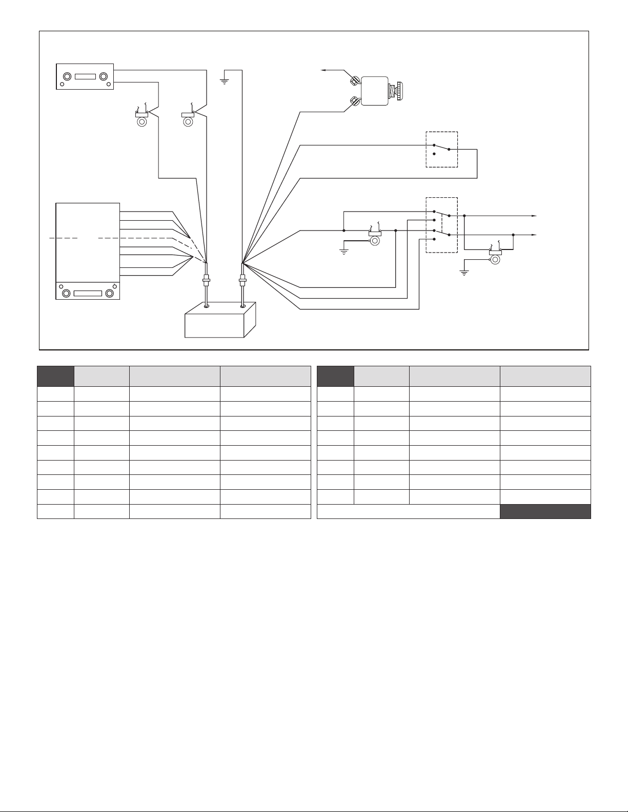
RES-2 Installation Drawing
To Aircraft
Power Buss
12 / 28 VDC
( P2-7 ) Red
INTERCOM
CIRCUIT
BREAKER
(1 AMP)
Notes:
1. Pilot / All switch and Passenger jacks not
used in single headset installations.
2. For mono headsets, remove wire from
headphone ring terminal and connect to
headphone tip terminal.
Aircraft
Hand Mic
Jack
Aircraft
Headphone
Jack
( P2-1 ) White / Red
On
Off
( P2-2 ) White / Red
( P2-5 ) Gray
( P2-3 ) Green
( P2-6 ) White / Black
( P2-4 ) White / Green
Ring
Barrel
Headphone
Pilot
Jack
Tip
All
Pilot
Barrel
Passenger
Headphone
Jack
To other
Passenger
headphone
TipRing
jacks
Headphone
or
Line Level
Output
Or
Speaker
Output
Stereo
Right
Common
Left
Right +
Right –
Left +
Left –
( J1-5 ) White
Violet ( J1-7 )
Black ( J1-4 )
Orange ( J1-1 )
W / Violet ( J1-8 )
W / Brown ( J1-9 )
Yellow ( J1-2 )
W / Yellow ( J1-3 )
( J1-6 ) Blue
J1
P1
RES-2
Music Switcher
( P2-8 ) Black
P2
J2
Figure 1
J1
Pin #
J1-1 Orange HDPH / Line output Lef t Channel P2-1 White / Red Music ON / OFF Music Switch ON
J1-2 Yellow Speaker Output Left Channel Positive P2-2 White / Red Music ON / OFF Music Switch Common
J1-3 White / Yellow Speaker Output Left Channel Negative P2-3 Green Pilot Right Channel Pilot Jack Tip
J1-4 Black HDPH / Line Common HDPH / Line Common P2-4 White / Green Passenger Right Channel Pilot / All Mode Selector SW
J1-5 White XMIT Music Disable Tip of Aircraft Mic Jack P2-5 Gray † Pilot Left Channel Pilot Jack Ring
J1-6 Blue
J1-7 Violet HDPH / Line output Right Channel P2-7 Red Power Input Aircraft Circuit Breaker 1 Amp
J1-8 White / Violet Speaker Output Right Channel Positive P2-8 Black Ground Aircraft Ground
J1-9 White / Brown Speaker Output Right Channel Negative Note: † Relevant to Stereo Installation Table 2
Wire
Color
Function Connect To:
Headphone Audio input
output Jack Tip
Aircraft Radio Headphone P2-6
P2
Pin #
Wire
Color
White / Black
Channel
Function Connect To:
† Passenger Left
Selector SW
Pilot / All Mode
CHASSIS INSTALLATION
Select a mounting location which will not cause interference with
flight controls. Four 6/32” screws with self locking nuts have been provided for mounting the chassis to the aircraft.
1. Remove the unit from the case.
2. After selecting a suitable mounting location in the aircraft, drill aircraft and switcher case with the same hole pattern. Use a No. 27 drill
(Clearance drill for 6/32”).
3. Secure case to the aircraft with the screw heads inside switcher case
for circuit board clearance.
4. Replace the unit in the case and secure.
WIRING INSTRUCTIONS
Four feet of cable has been provided to connect the unit to the aircraft
and entertainment system.
Figure 1 illustrates the connections to be made.
Table 2 lists the connector plugs and pin numbers, the color, function
and destination of each wire connected to those pins. Connections
should be made as shown in Figure 1 and as indicated in Table 2.
Sigtronics should be contacted if other means of connecting the unit
are contemplated.
OPERATING INSTRUCTIONS
Step 1. Turn aircraft radio “ON” and adjust both squelch (if manual)
and volume to suitable listening level.
Step 2. Turn Audio Switcher and entertainment system “ON” and
adjust entertainment to suitable listening level.
Step 3. Select Pilot or All position to suit switching mode desired.
Note: The Switcher controls can be changed from one mode to
another at any time. (See Mode Selection Table 1)
TRANSMIT: Transmitting is accomplished in the conventional manner,
by using your headset or hand-held microphone. Messages are received
via the headphones being worn. If the pilot has a headset with a boom
microphone and uses a push-to-talk switch, then the headset microphone plug should be connected to the aircraft microphone jack and
the headphone should be connected to the switcher headphone jack.
Sigtronics Corporation
178 East Arrow Highway
San Dimas, CA 91773
page 2
Phone: (909) 305-9399
E-mail: info@sigtronics.com
Web Site: www.sigtronics.com
10-27-2014 res2inst.pdf
 Loading...