

Page 1
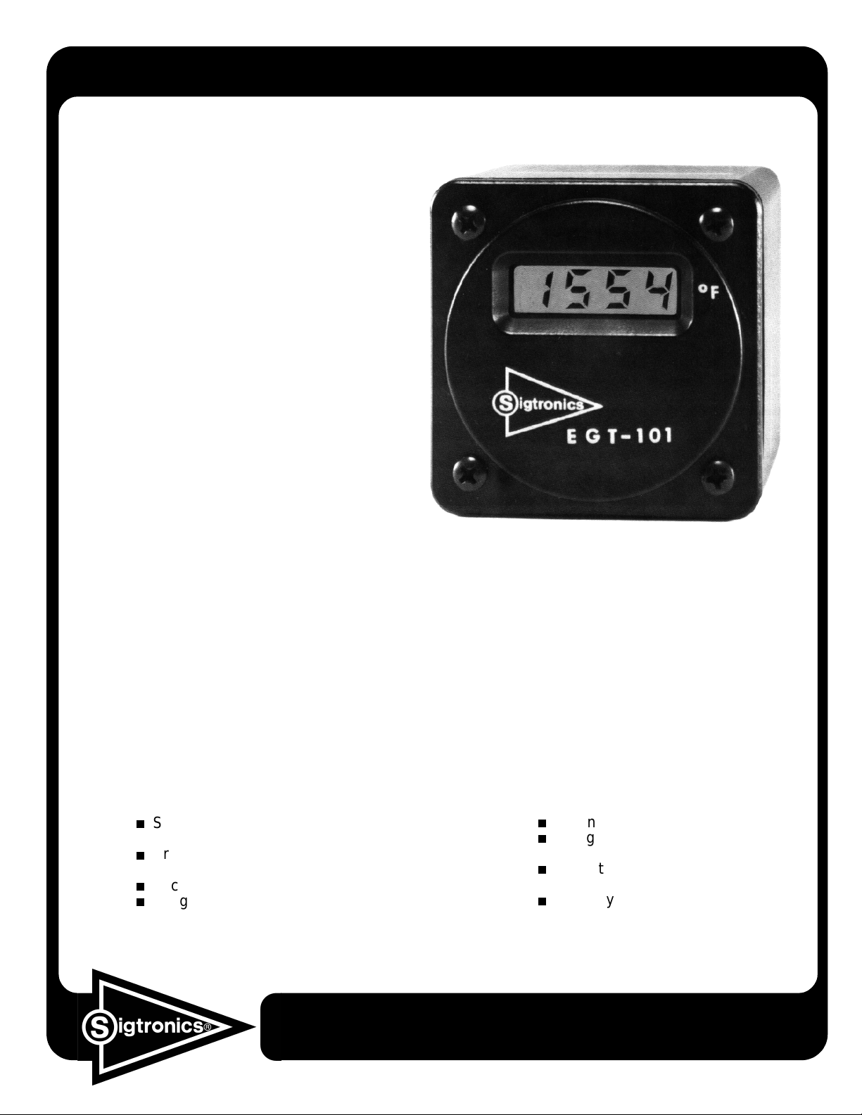
SIGTRONICS’ EGT 101
…The Digital EGT with a Difference!
Now you can upgrade
to DIGITAL without
replacing your probe.
Just pull out the old
analog and slip in the
New EGT 101; connect
to power and enjoy
Digital Accuracy,
Convenience and
Reliability!!
UNIQUE
■
use the EGT 101 to replace any EGT which uses the
conventional alum el/chromel (K Type) probe, regard less
of the probe “grounding” configuration. The K Type
probe, identified by it’s red (-) and yellow (+) lead
terminations, has been the standard probe for many
years.
LARGE LCD DISPLAY
■
Back lighting is provided for night flying. The lighting
circuit can also be connected to the aircraft panel light
dimmer circuit.
built-in isolation power supply allows you to
is easy to view i n the sunlig ht.
SPECIFICATIONS:
Single channel, however a switch may be installed for
multi-channel applications.
Probe input: Single alumel/chromel (K Type) probe.
Polarity marked mounting studs on rear of case.
Accuracy: ± 0.5% at 1500
Weight: 4.2 ounces
F
°
Serving You Since 1974
F RESOLUTION
■ 1°
maximum econom y and engine protection. Typical analog
gauges offer only 25° of resolution. Parallax error, resulting
from variance in viewing angle, further degrades the
readability of the analog gauge.
ADVANCED DESIGN
■
costly field calibration duri ng installation. The EGT 101 is
designed to read thermocouple vo ltage directly, therefore
the accuracy is not affected by thermocouple wire length
or gauge.
allows precise fuel leaning for
totally eliminates the need for
Dimensions: 2.5” x 2.5” x 3.5” deep
Voltage Requirement: 10-34VDC
Operates on 12V or 24V systems
Current Drain: 0.015 amps,
exclusive of lighting system.
Warranty: One year parts and labor
Made in U.S.A.
Specialists in “SOUND” Management
SIGTRONICS CORP. 178 East Arrow Highway, San Dimas, CA 91773 (909) 305-9399
Form EGT-2
Page 2

SIGTRONICS’ EGT 101 INSTALLATION INSTRUCTIONS
The Sigtronics’ EGT 101 Digital Exhaust Gas
Temperature meter is designed for mounting in the
conventional 2.25” instrument panel cutout. Parts
Supplied: 4 ea. mounting screws, power supply cable,
back-lighting kit.
BACK LIGHTING KIT - Prior to mounting the EGT,
determine the aircraft’s electrical system voltage. Then
select the proper voltage lam p from the backlighting kit.
The kit consists of a lam p socket and two wedge base
incandescent lamps.
ELECTRICAL CONNECTIONS
For 12V electrical s ystems, install the #73 lamp into
the lamp socket. A 24V system requires the #85 lamp.
(The lamp identification numbers appear on the bulb’s
glass envelope).
Install the lamp/socket assem bly into the hole on the
rear of the instrum ent case by inser ting and rotati ng 1/8
turn clockwise.
PIN NO. COLOR FUNCTION CONNECT TO
1RED
2BLACK
3WH/RED
4 WH/BLACK EGT Back-Light Ground
THERMOCOUPLE (Probe) CONNECTIONS
Two threaded studs protrude from the rear of the
instrument case to accommodate connections of the K
type thermocouple (chromel/alumel) probe to the EGT.
First, remove the outermost nuts from the smaller of the
EGT Power Input
12V or 24V
EGT Power Ground Aircraft Chassis Ground
EGT Back-Light Power Avionics Panel Lighting Dimmer Control
two studs (8-32) and install the negative (Red) thermocouple lead. Likewise, install the positive (Yellow)
thermocouple lead to the larger (10-32) stud on the EGT.
Hand tighten both terminal securing nuts.
OVERTIGHTEN!
Power through 1 amp inline fuse or
appropriate circuit breaker.
Aircraft Chassis Ground
DO NOT
 Loading...