

Page 1
Sigtronics AFPTT-1 Switch Installation Instructions
Foot Operated PTT Switch Wiring
When wiring up this device make sure power is off. Supply a cable
with flexible conductors (leads) to be prepared as shown. (See
Diagram)
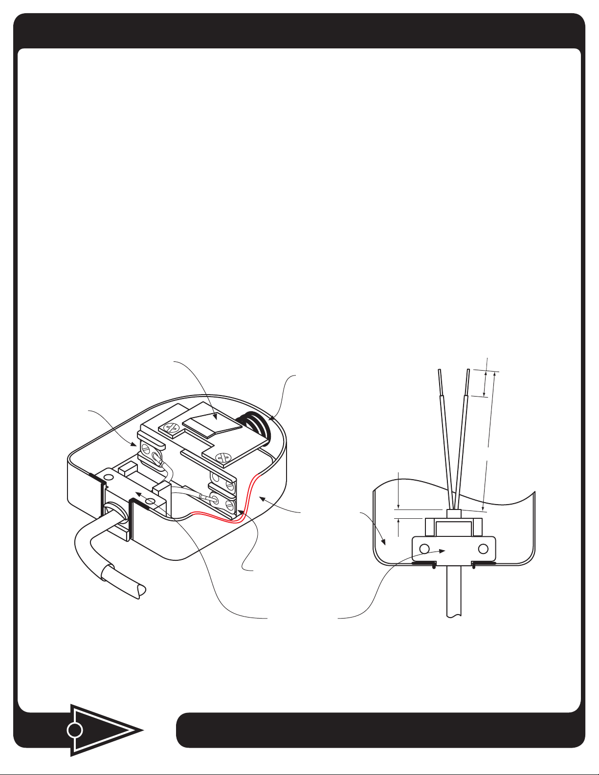
1. Remove hinge screws and cover. Please note how insulation
piece, actuator lever and actuator spring are oriented in the
event you choose to remove the interior switch for wiring.
2. For solder connections, strip the inner leads of your cable 3/8
inch and tin. Form 180˚ loops and trim excess after making
a mechanical connection and prior to soldering as shown.
A cable guard or bend relief must be provided that extends
beyond the cable clamp at least five times the overall diameter
of the flexible cable.
Actuator Lever
3. Solder lead connections as shown. NOTE: The switch is reversed
actuated. For example, the normally closed terminal marking
molded into the switch body will provide a normally open circuit
when the switch is assembled in the housing. Wiring the switch
as shown will give you a push-to-talk switch function.
4. Re-assemble the cover to the base with hinge screws and lock
washers.
The AFPTT-1 foot operated switch is furnished with a non-skid base
pad and can be mounted with the base pad attached. Use two
number 4 thread-cutting (self-tapping) screws and two number 4
lock washers when mounting.
0.375˝
Actuator Spring
Common
Cable Guard
2.0˝
0.125˝
Switch Base
Use this connection.
See Note
Cable
Cable Clamp
Cable
igtronics
S
®
Specialists in “SOUND” Management
178 East Arrow Highway, San Dimas, CA 91773 ( 909 ) 305-9399
12-19-2011 AFPTT-1_Inst .pdf
Page 2
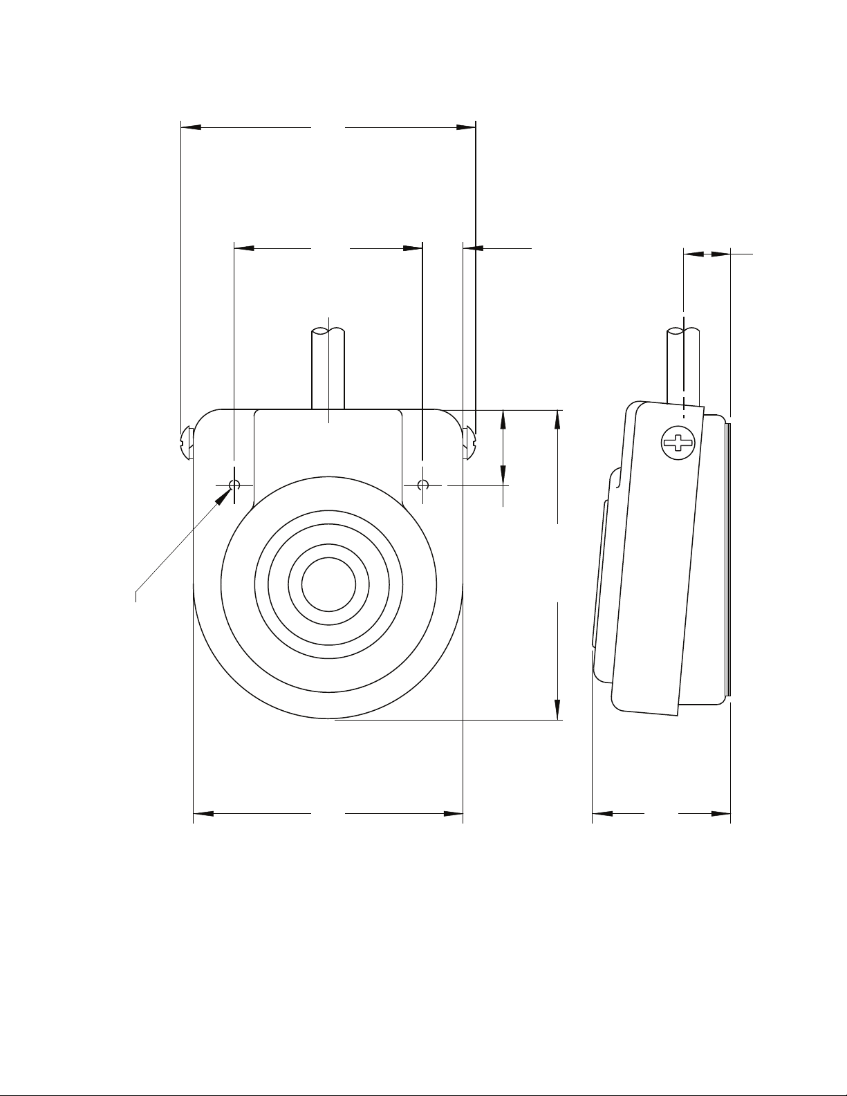
2.737 IN.
(69.52mm)
1.750 IN.
(44.45mm)
.704 IN.
(17.88mm)
.375 IN.
(9.53mm)
2.875 IN.
(73.02mm)
.438 IN.
(11.13mm)
(2 PLACES)
.096 IN. (2.44mm)
MOUNTING HOLES
ALL DIMENSIONS ARE FOR REFERENCE ONLY
NOT DRAWN TO SCALE
Sigtronics AFPTT Switch
NOTE:
2.500 IN.
(63.50mm)
1.281 IN.
(32.54mm)
 Loading...