

Page 1

Sigtronics 900092 Adapter Installation Instructions
Description
The Sigtronics 900092 “Y” adapter is designed to simplify the process of
connecting a Sigtronics intercom or MRIM-2 system to radios that use the
6 pin NATO connector like the Harris manpack radio. See the Sigtronics
web site for specific models.
Installation
1. Unplug the handset from the radio. Push in and twist the connector
plug to disconnect it from the radio and plug it into the jack on the
900092 adapter module. You may also have to unhook the cable strain
relief from the radio.
2. Plug the cord connector of the Sigtronics 900092 adapter into the
handset connector on radio.
3. To select an appropriate mounting location for the adapter, first connect
it up to the radio. To do this, unscrew and remove the two screws on the
top of the 900092 adapter. Leave the lid in place on the adapter for now.
4. Now you are ready to select a mounting location for the adapter. Select
a spot out of the way so that the adapter and its cables will not interfere
with the normal operation of the vehicle. Note: One more cable will have
to come out of the adapter for the wires that go to Sigtronics intercom
or MRIM-2 unit. This cable can come out of any side of the adapter except the top. For convenience, the bottom of the adapter already has
a hole for this. Make sure that the handset has enough cable length to
be used properly.
5. Hold the adapter on the intended mounting place, remove the adapter
lid, and carefully slide the PCB out of its slot. Mark with a pen or pencil
through the two mounting holes and the cable hole (if desired) on the
bottom of the adapter. Note: As an option to using the sheet metal
screws, the included double sided foam tape may be used to mount the
adapter. If the cable to the Sigtronics intercom or MRIM-2 unit needs to
come out the side of the adapter mark that hole also. Note: Cable holes
on the side of the adapter should be as close to the bottom as possible
to clear the adapter lid. Drill all the holes and mount with the supplied
#10 sheet metal screws.
6. Route the cable from the intercom or MRIM-2 unit through the hole on
the adapter. Note: Use the wire supplied with the Sigtronics system for
connection to the 900092 adapter terminal block. If unavailable use wire
that has 22 or 24 gauge stranded conductors. Cut to length but leave a
few inches for access.
7. Strip the insulation from the individual conductors about 1/2 inch. Twist
the conductors to eliminate any loose strands and insert the wires into
the terminal block holes. See drawing on back for color code. To insert
the wire, use a finger nail or small screw driver, press and hold the selected orange tab towards the circuit board and insert the wire into the
matching hole. Make sure the wire is inserted enough into the hole that
insulation touches the hole entry (no exposed bare wire). Release the
tab. Carefully inspect and fix any loose wire strands that did not make it
into the hole. Repeat for all wires. Reinstall the PCB in the slot.
8. Install the provided tie wrap securely on the intercom or MRIM-2 cable
so that the wires won’t pull out of the adapter box.
9. Replace the adapter box lid making sure the wires do not get pinched
around the edges. Reinstall the lid screws. Put the handset cable strain
relief hook into the eyelet on the corner of the adapter if applicable.
NOTES: Don’t forget to also hook up the speaker wires (2 violet wires)
from the Sigtronics intercom or MRIM-2 unit to the radio speaker leads.
Adjust the Sigtronics intercom or MRIM-2 units transmit and receive levels
per their appropriate installation instructions. Your existing radio handset
and speaker will still function as normal.
WARRANTY: One year parts and labor.
Standard Equipment Included
Part Description Part Number Quantity
Box Cover Screws 100429 2
Box Mounting Screws 100452 2
Foam, Double Sided 100720 1
Tie Wrap 100450 1
Wire Grommet 100049 1
igtronics
S
®
Specialists in “SOUND” Management
178 East Arrow Highway, San Dimas, CA 91773 (909) 305-9399
Page 2
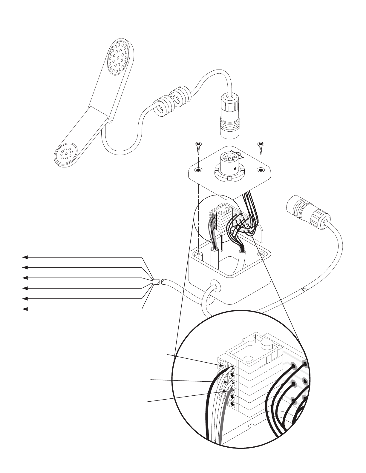
Handset
Sigtronics 900092 “Y” Adapter
Plug your handset into the
900092 adapter.
D
Plug this connector into
your manpack radio.
900092
“Y” Adapter
Terminal Block A: Mic Low, PTT Low, Speaker Low
Terminal Block B: Speaker High
Terminal Block C: PTT High
Terminal Block D: Mic High
Terminal Block E: Exp
Terminal Block F: Ext
The wire color below is for Sigtronics
emergency wiring connections.
Black & White: Mic & PTT Low. To terminal block A
Either White: PTT Low. To terminal block C
Brown: Mic High. To terminal block D
-2,54
D-FFKDS 1
A
B
C
D
E
F
-2,54
D-FFKDS 1
A
B
C
D
E
F
2-10-2014 900092.pdf
 Loading...