

SigTEL EVCS, EVC302F, EVC302S Quick Start Installation Manual
THIS GUIDE IS FOR EXPERIENCED INSTALLERS ONLY and summarises key information provided in the full manual (Document No. DAU0000081). Page numbers, e.g. refer to the main manual.
Networked systems are not included in this guide.
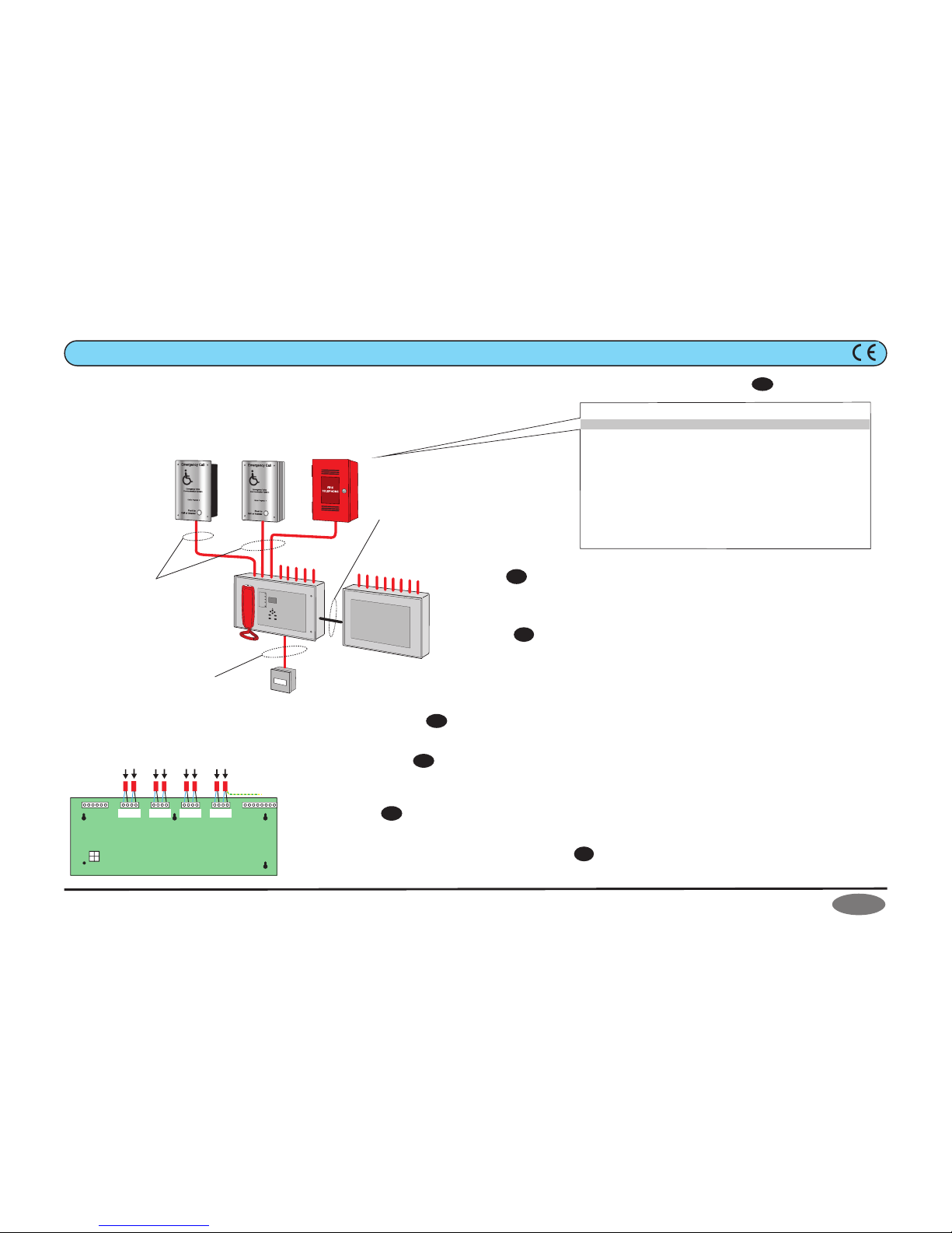
SigTEL (1-16 Line) EVCS - Quick Start Installation Guide
F
U
S
E
8 x
outstation lines
EVC302F
THS1-E/MK4
ECU-8
EVC302S
3A fused spur
ECU-8S
(optional)
8 lines of 2-core (1.5mm
2
) and
earth/CPC cable, enhanced
fire-rated, up to 1km in length.
Master/Slave interconnection via
supplied looms and short length of
steel conduit (25mm OD, max. length
60mm). Mount slave directly adjacent
to the master.
Fixed wiring, 2-core and earth/cpc
cable (0.75mm
2
to 2.5mm2) fed from
switched spur, fused at 3 amps.
additional
outstations
1 of 2
Approved Document No. DAU0302001 Rev 1
SigTEL
Emergency Voice
Communication System
SigTEL EVCS Wiring Overview
Install the EVCS
Location
Site all equipment indoors in well-lit areas, free from obstruction. If background noise exceeds 40 dB, use
an acoustic hood. Site control unit(s) in the control room or lobby, 1.4 metre above final floor level (FFL).
Fit Type A (fire telephone) outstations in fire fighting lobbies and fire access points, 1.3 to 1.4 metres
above FFL. Fit type B (disabled refuge) outstations in disabled refuges, 0.9 to 1.0 metre above FFL.
Mounting
Remove base PCBs before first fix installation to protect them and expose the base mounting holes.
Wall mount the control units, either surface or semi-flush. Fix the base securely onto a wall using No. 8
round-head, or countersunk screws. If an optional ECU-8S is fitted make the interconnections to the
ECU-8 using supplied looms and short length of steel conduit (25 mm OD, max. length 60 mm).
After mounting, remove any dust/swarf and re-install base PCBs. Ensure all connecting looms are refitted
correctly; ECU-8 internal connections are B to B, C to C. ECU-8 to ECU-8S (optional) is A to A, D to B.
P
g11
Pg11
Wiring and Cable Entry
See Fig 1 above for cable types. Install all wiring in accordance with the current edition of the IEE Wiring Regs (BS 7671), or relevant national
standards. Use enhanced fire-rated cables between outstations and control equipment.
Test Outstation Lines
Test all lines for faults before terminating outstation lines to the ECU-8/ECU-8S. In addition, test outstation lines using a FITT telephone line
tester (see component list above).
CAUTION: DO NOT use an Insulation Resistance Tester (Megger) with any devices connected as they will be destroyed.
Fit Outstations
See Fig 1 above for cable type. Maximum recommended cable distance is 1 km, beyond which audio quality may degrade. For wiring and
connection details refer to Type A outstation instructions (Doc. No. DAU0000001) and Type B outstation instructions (Doc. No. DAU0302000).
Connect Outstation Lines to the Control Equipment
Do not connect outstation lines to the ECU-8, or optional ECU-8S, until they have been tested, fault-free and suitable cable glands fitted.
Connect outstation lines directly to the Exchange PCB (see Fig 2 left). Connect screens to the earth terminal in the back of the enclosure.
8 x Lines from Type A or Type B Outstations
L1 L2
+ - + -
L3 L4
+ - + -
L5 L6
+ - + -
L7 L8
+ - + -
I/P A I/P B I/P C
N/O C N/C 0V +24 OP3 OP2 OP1
+ - + - + -
All screens connect
to Earth terminal
ECU-8 or ECU-8S
Exchange PCB
A
CD
B
Fig 2
Pg12
Pg7
Pg18
Pg19
P
art No.Description
ECU-8 8-line Master EVC Control Unit c/w line cards, handset and LCD
ECU-8S 8-line Slave EVC Expansion Unit (expands ECU-8 to 16 lines)
EVC302F Disabled Refuge (Type B) Outstation, handsfree, duplex, flush mounted
EVC302S Disabled Refuge (Type B) Outstation, handsfree, duplex, surface mounted
T
HS1-E/MK4Fire Telephone (Type A) Outstation c/w red steel case, handset & key
T
HS1-ET/MK4Fire Telephone (Type A) Outstation c/w red steel case, handset & T-Bar
B
F359/1Weatherproof enclosure for EVC302F
B
F359/2Anti-tamper enclosure for ECU-8 or ECU-8S
FITT EVC Telephone Line Tester
BC286/2 24 V, 7 Ah battery used with ECU-8
AFP385 Grey flush bezel for ECU-8 or ECU-8S
T-BEZ Red flush bezel for THS1-E/MK4 and THS1-ET/MK4
SigTEL EVCS Components
Pg19
Fig 1
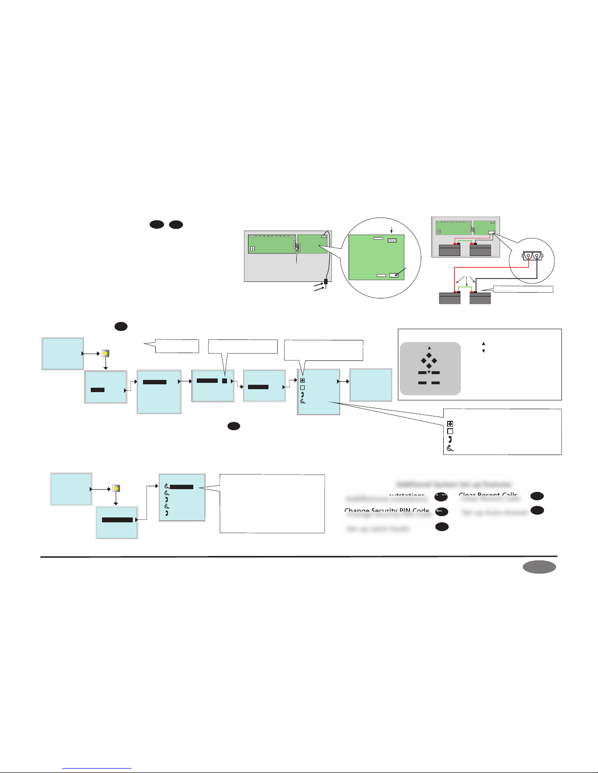
Commission the EVCS
Eng. Opts.
System Healthy
Name List
>
Config
About...
Edit Phonebook
E
> Extension 1
Extension 2
Extension 3
Extension 4
Extension 5
Press Engineer Mode button
(located on back of ECU-8 lid)
SigTEL
Compact
Note: Before commissioning the system ensure that all equipment is fully installed, connected and wiring tested.
Check all handsets are on-hook and the ECU-8 shows ‘System Healthy’ status at its LCD display. Configure the system by following the flow chart below.
Naming Outstations
Select ‘Edit Phonebook’ option.
and - highlights extension
ACCEPT - selects 1st character
and - changes character
ACCEPT - moves to next character
HOLD - moves to previous character & exits
DIRECTORY - saves changes
At the ECU-8, with the handset on-hook, select the ‘Edit Phonebook’ option by following the flow chart below. With an operator at the ECU-8, go to
the first outstation turn and make a call. At the ECU-8 lift the handset and press the ACCEPT button. The outstation’s channel is opened for speech and
automatically selected for editing. Check audio quality of the line and inform the operator at the ECU-8 your position. They can edit the outstation
name directly (see Naming Outstations below). Repeat this process for all remaining outstations but to avoid confusion only call in from one outstation
at a time. Outstations can also be manually named if you are sure of its location (see Naming Outstations below).
Press Engineer Mode button
(located on back of ECU-8 lid)
>
Change PIN
System Opts
Harmonise Names
Reset Names
Factory Dfts
Config
: 1
: 0
: 3
: 13
System Updated
Auto Learn
SigTEL
Compact
System Healthy
SigTEL
Compact
Edit Phonebook
>
About...
Eng. Opts.
Config
System Cfg
Syst Cfg
System Healthy
>Unit Count 1
Auto Learn
Syst Cfg
Unit Count 1
>Auto Learn
Configure the system
4
H
OLD
CALL/
ACCEPT
FUNCTION
DIRECTORY
S
ILENCE
BUZZER
1
2
3
CALL/ACC EPT
= SELECT
HOLD
= BACK TO PREVIOUS DISPLAY & LAMP TEST
FUNCTION (1)
= EDIT EXT. NAMES & PIN CODE ENTRY
DIRECTORY (2)
SILENCE (3)
BUZZER
= SILENCE BUZZER & PIN CODE ENTRY
(4)
=
CANCEL EDIT EXT. NAMES & PIN CODE ENTRY
= SCROLL UP
= SCROLL DOWN
Using the ECU-8 keypad
2 of 2
Approved Document No. DAU0302001 Rev 1
SigTEL
Emergency Voice
Communication System
Errors and omissions excepted. No responsibility can be accepted by the manufacturer or distributors of this product for any misinterpretation of this instruction, or for the compliance of the system as a whole. The manufacturers policy is one of continuous
improvement and we reserve the right to make changes to product specifications at our discretion and without prior notice.
Change Security PIN Code
Connecting Mains and Batteries
See Fig 1 overleaf for mains cable type. Connect a suitable 230 Vac supply
to the ECU-8 via the base knockouts. Terminate the mains cable at the
Power Supply PCB (plug P2) and NOT to main earth chassis (see Fig 3 right).
For the emergency standby power supply, only use good quality, sealed
VRLA batteries. Position and connect two 12 Vdc, 7 Ah batteries to the
ECU-8 using the supplied battery connection leads (see Fig 4 right).
P
g17
Pg29
Set up Latch Faults
Pg30
Clear Recent Calls
Pg31
Set up Auto-Answer
Pg31
Add/Remove outstations
Pg27
Check audio quality and interactively name outstations
Pg27
Pg24
24V
battery connection
leads (supplied)
12V, 7Ah
+
–
+
–
GND
12V, 7Ah
A
B
C
D
12V, 7Ah
+
–
+
–
12V, 7Ah
ECU
-8
B
attery Connector
Exchange PCB
Power Supply
PCB
A
B
C
D
2
30 Vac
Mains Fuse
1 A HRC
L E N
Batt fuse
1 A (F)
Power Supply
P
CB
T
o 3A fused spur
Cable gland
Power Supply loom
Battery
Connector
P2
Power Supply
PCB
ECU-8
Exchange PCB
Fig 3
Fig 4
- No. ECU-8 units (should be set to 1)
- No. ECU-8NT units (networked systems only)
- No. Type A (fire telephone) outstations
- No. Type B (disabled refuge) outstations
What the symbols mean
Additional System Set up Features
Check the unit count
(number of ECU-8) is set to 1
Pg22
Check the number of ECU-8 and
outstations match the number
connected on the system
Observe correct polarity!
DO NOT press the
Reset button!
 Loading...